EP3730264A1 - Préimprégné en forme de bande et son procédé de production - Google Patents
Préimprégné en forme de bande et son procédé de production Download PDFInfo
- Publication number
- EP3730264A1 EP3730264A1 EP18892541.6A EP18892541A EP3730264A1 EP 3730264 A1 EP3730264 A1 EP 3730264A1 EP 18892541 A EP18892541 A EP 18892541A EP 3730264 A1 EP3730264 A1 EP 3730264A1
- Authority
- EP
- European Patent Office
- Prior art keywords
- tape
- shaped prepreg
- shaped
- cooling mechanism
- cooling
- Prior art date
- Legal status (The legal status is an assumption and is not a legal conclusion. Google has not performed a legal analysis and makes no representation as to the accuracy of the status listed.)
- Granted
Links
Images


Classifications
-
- B—PERFORMING OPERATIONS; TRANSPORTING
- B29—WORKING OF PLASTICS; WORKING OF SUBSTANCES IN A PLASTIC STATE IN GENERAL
- B29B—PREPARATION OR PRETREATMENT OF THE MATERIAL TO BE SHAPED; MAKING GRANULES OR PREFORMS; RECOVERY OF PLASTICS OR OTHER CONSTITUENTS OF WASTE MATERIAL CONTAINING PLASTICS
- B29B15/00—Pretreatment of the material to be shaped, not covered by groups B29B7/00 - B29B13/00
- B29B15/08—Pretreatment of the material to be shaped, not covered by groups B29B7/00 - B29B13/00 of reinforcements or fillers
- B29B15/10—Coating or impregnating independently of the moulding or shaping step
- B29B15/12—Coating or impregnating independently of the moulding or shaping step of reinforcements of indefinite length
-
- B—PERFORMING OPERATIONS; TRANSPORTING
- B29—WORKING OF PLASTICS; WORKING OF SUBSTANCES IN A PLASTIC STATE IN GENERAL
- B29B—PREPARATION OR PRETREATMENT OF THE MATERIAL TO BE SHAPED; MAKING GRANULES OR PREFORMS; RECOVERY OF PLASTICS OR OTHER CONSTITUENTS OF WASTE MATERIAL CONTAINING PLASTICS
- B29B15/00—Pretreatment of the material to be shaped, not covered by groups B29B7/00 - B29B13/00
- B29B15/08—Pretreatment of the material to be shaped, not covered by groups B29B7/00 - B29B13/00 of reinforcements or fillers
- B29B15/10—Coating or impregnating independently of the moulding or shaping step
- B29B15/12—Coating or impregnating independently of the moulding or shaping step of reinforcements of indefinite length
- B29B15/122—Coating or impregnating independently of the moulding or shaping step of reinforcements of indefinite length with a matrix in liquid form, e.g. as melt, solution or latex
-
- B—PERFORMING OPERATIONS; TRANSPORTING
- B29—WORKING OF PLASTICS; WORKING OF SUBSTANCES IN A PLASTIC STATE IN GENERAL
- B29B—PREPARATION OR PRETREATMENT OF THE MATERIAL TO BE SHAPED; MAKING GRANULES OR PREFORMS; RECOVERY OF PLASTICS OR OTHER CONSTITUENTS OF WASTE MATERIAL CONTAINING PLASTICS
- B29B11/00—Making preforms
- B29B11/14—Making preforms characterised by structure or composition
- B29B11/16—Making preforms characterised by structure or composition comprising fillers or reinforcement
-
- B—PERFORMING OPERATIONS; TRANSPORTING
- B29—WORKING OF PLASTICS; WORKING OF SUBSTANCES IN A PLASTIC STATE IN GENERAL
- B29C—SHAPING OR JOINING OF PLASTICS; SHAPING OF MATERIAL IN A PLASTIC STATE, NOT OTHERWISE PROVIDED FOR; AFTER-TREATMENT OF THE SHAPED PRODUCTS, e.g. REPAIRING
- B29C70/00—Shaping composites, i.e. plastics material comprising reinforcements, fillers or preformed parts, e.g. inserts
- B29C70/04—Shaping composites, i.e. plastics material comprising reinforcements, fillers or preformed parts, e.g. inserts comprising reinforcements only, e.g. self-reinforcing plastics
- B29C70/06—Fibrous reinforcements only
- B29C70/10—Fibrous reinforcements only characterised by the structure of fibrous reinforcements, e.g. hollow fibres
- B29C70/16—Fibrous reinforcements only characterised by the structure of fibrous reinforcements, e.g. hollow fibres using fibres of substantial or continuous length
- B29C70/20—Fibrous reinforcements only characterised by the structure of fibrous reinforcements, e.g. hollow fibres using fibres of substantial or continuous length oriented in a single direction, e.g. roofing or other parallel fibres
-
- B—PERFORMING OPERATIONS; TRANSPORTING
- B29—WORKING OF PLASTICS; WORKING OF SUBSTANCES IN A PLASTIC STATE IN GENERAL
- B29C—SHAPING OR JOINING OF PLASTICS; SHAPING OF MATERIAL IN A PLASTIC STATE, NOT OTHERWISE PROVIDED FOR; AFTER-TREATMENT OF THE SHAPED PRODUCTS, e.g. REPAIRING
- B29C70/00—Shaping composites, i.e. plastics material comprising reinforcements, fillers or preformed parts, e.g. inserts
- B29C70/04—Shaping composites, i.e. plastics material comprising reinforcements, fillers or preformed parts, e.g. inserts comprising reinforcements only, e.g. self-reinforcing plastics
- B29C70/28—Shaping operations therefor
- B29C70/40—Shaping or impregnating by compression not applied
- B29C70/50—Shaping or impregnating by compression not applied for producing articles of indefinite length, e.g. prepregs, sheet moulding compounds [SMC] or cross moulding compounds [XMC]
- B29C70/52—Pultrusion, i.e. forming and compressing by continuously pulling through a die
-
- B—PERFORMING OPERATIONS; TRANSPORTING
- B29—WORKING OF PLASTICS; WORKING OF SUBSTANCES IN A PLASTIC STATE IN GENERAL
- B29C—SHAPING OR JOINING OF PLASTICS; SHAPING OF MATERIAL IN A PLASTIC STATE, NOT OTHERWISE PROVIDED FOR; AFTER-TREATMENT OF THE SHAPED PRODUCTS, e.g. REPAIRING
- B29C70/00—Shaping composites, i.e. plastics material comprising reinforcements, fillers or preformed parts, e.g. inserts
- B29C70/04—Shaping composites, i.e. plastics material comprising reinforcements, fillers or preformed parts, e.g. inserts comprising reinforcements only, e.g. self-reinforcing plastics
- B29C70/28—Shaping operations therefor
- B29C70/40—Shaping or impregnating by compression not applied
- B29C70/50—Shaping or impregnating by compression not applied for producing articles of indefinite length, e.g. prepregs, sheet moulding compounds [SMC] or cross moulding compounds [XMC]
- B29C70/52—Pultrusion, i.e. forming and compressing by continuously pulling through a die
- B29C70/525—Component parts, details or accessories; Auxiliary operations
- B29C70/528—Heating or cooling
-
- B—PERFORMING OPERATIONS; TRANSPORTING
- B32—LAYERED PRODUCTS
- B32B—LAYERED PRODUCTS, i.e. PRODUCTS BUILT-UP OF STRATA OF FLAT OR NON-FLAT, e.g. CELLULAR OR HONEYCOMB, FORM
- B32B5/00—Layered products characterised by the non- homogeneity or physical structure, i.e. comprising a fibrous, filamentary, particulate or foam layer; Layered products characterised by having a layer differing constitutionally or physically in different parts
- B32B5/22—Layered products characterised by the non- homogeneity or physical structure, i.e. comprising a fibrous, filamentary, particulate or foam layer; Layered products characterised by having a layer differing constitutionally or physically in different parts characterised by the presence of two or more layers which are next to each other and are fibrous, filamentary, formed of particles or foamed
- B32B5/24—Layered products characterised by the non- homogeneity or physical structure, i.e. comprising a fibrous, filamentary, particulate or foam layer; Layered products characterised by having a layer differing constitutionally or physically in different parts characterised by the presence of two or more layers which are next to each other and are fibrous, filamentary, formed of particles or foamed one layer being a fibrous or filamentary layer
- B32B5/26—Layered products characterised by the non- homogeneity or physical structure, i.e. comprising a fibrous, filamentary, particulate or foam layer; Layered products characterised by having a layer differing constitutionally or physically in different parts characterised by the presence of two or more layers which are next to each other and are fibrous, filamentary, formed of particles or foamed one layer being a fibrous or filamentary layer another layer next to it also being fibrous or filamentary
-
- C—CHEMISTRY; METALLURGY
- C08—ORGANIC MACROMOLECULAR COMPOUNDS; THEIR PREPARATION OR CHEMICAL WORKING-UP; COMPOSITIONS BASED THEREON
- C08J—WORKING-UP; GENERAL PROCESSES OF COMPOUNDING; AFTER-TREATMENT NOT COVERED BY SUBCLASSES C08B, C08C, C08F, C08G or C08H
- C08J5/00—Manufacture of articles or shaped materials containing macromolecular substances
- C08J5/24—Impregnating materials with prepolymers which can be polymerised in situ, e.g. manufacture of prepregs
- C08J5/241—Impregnating materials with prepolymers which can be polymerised in situ, e.g. manufacture of prepregs using inorganic fibres
- C08J5/243—Impregnating materials with prepolymers which can be polymerised in situ, e.g. manufacture of prepregs using inorganic fibres using carbon fibres
-
- B—PERFORMING OPERATIONS; TRANSPORTING
- B29—WORKING OF PLASTICS; WORKING OF SUBSTANCES IN A PLASTIC STATE IN GENERAL
- B29C—SHAPING OR JOINING OF PLASTICS; SHAPING OF MATERIAL IN A PLASTIC STATE, NOT OTHERWISE PROVIDED FOR; AFTER-TREATMENT OF THE SHAPED PRODUCTS, e.g. REPAIRING
- B29C70/00—Shaping composites, i.e. plastics material comprising reinforcements, fillers or preformed parts, e.g. inserts
- B29C70/04—Shaping composites, i.e. plastics material comprising reinforcements, fillers or preformed parts, e.g. inserts comprising reinforcements only, e.g. self-reinforcing plastics
- B29C70/28—Shaping operations therefor
- B29C70/40—Shaping or impregnating by compression not applied
- B29C70/50—Shaping or impregnating by compression not applied for producing articles of indefinite length, e.g. prepregs, sheet moulding compounds [SMC] or cross moulding compounds [XMC]
- B29C70/52—Pultrusion, i.e. forming and compressing by continuously pulling through a die
- B29C70/521—Pultrusion, i.e. forming and compressing by continuously pulling through a die and impregnating the reinforcement before the die
-
- B—PERFORMING OPERATIONS; TRANSPORTING
- B29—WORKING OF PLASTICS; WORKING OF SUBSTANCES IN A PLASTIC STATE IN GENERAL
- B29K—INDEXING SCHEME ASSOCIATED WITH SUBCLASSES B29B, B29C OR B29D, RELATING TO MOULDING MATERIALS OR TO MATERIALS FOR MOULDS, REINFORCEMENTS, FILLERS OR PREFORMED PARTS, e.g. INSERTS
- B29K2077/00—Use of PA, i.e. polyamides, e.g. polyesteramides or derivatives thereof, as moulding material
-
- B—PERFORMING OPERATIONS; TRANSPORTING
- B29—WORKING OF PLASTICS; WORKING OF SUBSTANCES IN A PLASTIC STATE IN GENERAL
- B29K—INDEXING SCHEME ASSOCIATED WITH SUBCLASSES B29B, B29C OR B29D, RELATING TO MOULDING MATERIALS OR TO MATERIALS FOR MOULDS, REINFORCEMENTS, FILLERS OR PREFORMED PARTS, e.g. INSERTS
- B29K2101/00—Use of unspecified macromolecular compounds as moulding material
- B29K2101/12—Thermoplastic materials
-
- B—PERFORMING OPERATIONS; TRANSPORTING
- B29—WORKING OF PLASTICS; WORKING OF SUBSTANCES IN A PLASTIC STATE IN GENERAL
- B29K—INDEXING SCHEME ASSOCIATED WITH SUBCLASSES B29B, B29C OR B29D, RELATING TO MOULDING MATERIALS OR TO MATERIALS FOR MOULDS, REINFORCEMENTS, FILLERS OR PREFORMED PARTS, e.g. INSERTS
- B29K2105/00—Condition, form or state of moulded material or of the material to be shaped
- B29K2105/06—Condition, form or state of moulded material or of the material to be shaped containing reinforcements, fillers or inserts
- B29K2105/08—Condition, form or state of moulded material or of the material to be shaped containing reinforcements, fillers or inserts of continuous length, e.g. cords, rovings, mats, fabrics, strands or yarns
- B29K2105/0872—Prepregs
-
- B—PERFORMING OPERATIONS; TRANSPORTING
- B29—WORKING OF PLASTICS; WORKING OF SUBSTANCES IN A PLASTIC STATE IN GENERAL
- B29K—INDEXING SCHEME ASSOCIATED WITH SUBCLASSES B29B, B29C OR B29D, RELATING TO MOULDING MATERIALS OR TO MATERIALS FOR MOULDS, REINFORCEMENTS, FILLERS OR PREFORMED PARTS, e.g. INSERTS
- B29K2105/00—Condition, form or state of moulded material or of the material to be shaped
- B29K2105/06—Condition, form or state of moulded material or of the material to be shaped containing reinforcements, fillers or inserts
- B29K2105/08—Condition, form or state of moulded material or of the material to be shaped containing reinforcements, fillers or inserts of continuous length, e.g. cords, rovings, mats, fabrics, strands or yarns
- B29K2105/0872—Prepregs
- B29K2105/0881—Prepregs unidirectional
-
- B—PERFORMING OPERATIONS; TRANSPORTING
- B29—WORKING OF PLASTICS; WORKING OF SUBSTANCES IN A PLASTIC STATE IN GENERAL
- B29K—INDEXING SCHEME ASSOCIATED WITH SUBCLASSES B29B, B29C OR B29D, RELATING TO MOULDING MATERIALS OR TO MATERIALS FOR MOULDS, REINFORCEMENTS, FILLERS OR PREFORMED PARTS, e.g. INSERTS
- B29K2307/00—Use of elements other than metals as reinforcement
- B29K2307/04—Carbon
-
- B—PERFORMING OPERATIONS; TRANSPORTING
- B32—LAYERED PRODUCTS
- B32B—LAYERED PRODUCTS, i.e. PRODUCTS BUILT-UP OF STRATA OF FLAT OR NON-FLAT, e.g. CELLULAR OR HONEYCOMB, FORM
- B32B2307/00—Properties of the layers or laminate
- B32B2307/50—Properties of the layers or laminate having particular mechanical properties
- B32B2307/538—Roughness
-
- C—CHEMISTRY; METALLURGY
- C08—ORGANIC MACROMOLECULAR COMPOUNDS; THEIR PREPARATION OR CHEMICAL WORKING-UP; COMPOSITIONS BASED THEREON
- C08J—WORKING-UP; GENERAL PROCESSES OF COMPOUNDING; AFTER-TREATMENT NOT COVERED BY SUBCLASSES C08B, C08C, C08F, C08G or C08H
- C08J2377/00—Characterised by the use of polyamides obtained by reactions forming a carboxylic amide link in the main chain; Derivatives of such polymers
-
- Y—GENERAL TAGGING OF NEW TECHNOLOGICAL DEVELOPMENTS; GENERAL TAGGING OF CROSS-SECTIONAL TECHNOLOGIES SPANNING OVER SEVERAL SECTIONS OF THE IPC; TECHNICAL SUBJECTS COVERED BY FORMER USPC CROSS-REFERENCE ART COLLECTIONS [XRACs] AND DIGESTS
- Y10—TECHNICAL SUBJECTS COVERED BY FORMER USPC
- Y10T—TECHNICAL SUBJECTS COVERED BY FORMER US CLASSIFICATION
- Y10T428/00—Stock material or miscellaneous articles
- Y10T428/249921—Web or sheet containing structurally defined element or component
- Y10T428/249924—Noninterengaged fiber-containing paper-free web or sheet which is not of specified porosity
- Y10T428/24994—Fiber embedded in or on the surface of a polymeric matrix
-
- Y—GENERAL TAGGING OF NEW TECHNOLOGICAL DEVELOPMENTS; GENERAL TAGGING OF CROSS-SECTIONAL TECHNOLOGIES SPANNING OVER SEVERAL SECTIONS OF THE IPC; TECHNICAL SUBJECTS COVERED BY FORMER USPC CROSS-REFERENCE ART COLLECTIONS [XRACs] AND DIGESTS
- Y10—TECHNICAL SUBJECTS COVERED BY FORMER USPC
- Y10T—TECHNICAL SUBJECTS COVERED BY FORMER US CLASSIFICATION
- Y10T428/00—Stock material or miscellaneous articles
- Y10T428/249921—Web or sheet containing structurally defined element or component
- Y10T428/249924—Noninterengaged fiber-containing paper-free web or sheet which is not of specified porosity
- Y10T428/24994—Fiber embedded in or on the surface of a polymeric matrix
- Y10T428/249942—Fibers are aligned substantially parallel
-
- Y—GENERAL TAGGING OF NEW TECHNOLOGICAL DEVELOPMENTS; GENERAL TAGGING OF CROSS-SECTIONAL TECHNOLOGIES SPANNING OVER SEVERAL SECTIONS OF THE IPC; TECHNICAL SUBJECTS COVERED BY FORMER USPC CROSS-REFERENCE ART COLLECTIONS [XRACs] AND DIGESTS
- Y10—TECHNICAL SUBJECTS COVERED BY FORMER USPC
- Y10T—TECHNICAL SUBJECTS COVERED BY FORMER US CLASSIFICATION
- Y10T428/00—Stock material or miscellaneous articles
- Y10T428/249921—Web or sheet containing structurally defined element or component
- Y10T428/249924—Noninterengaged fiber-containing paper-free web or sheet which is not of specified porosity
- Y10T428/24994—Fiber embedded in or on the surface of a polymeric matrix
- Y10T428/249942—Fibers are aligned substantially parallel
- Y10T428/249944—Fiber is precoated
-
- Y—GENERAL TAGGING OF NEW TECHNOLOGICAL DEVELOPMENTS; GENERAL TAGGING OF CROSS-SECTIONAL TECHNOLOGIES SPANNING OVER SEVERAL SECTIONS OF THE IPC; TECHNICAL SUBJECTS COVERED BY FORMER USPC CROSS-REFERENCE ART COLLECTIONS [XRACs] AND DIGESTS
- Y10—TECHNICAL SUBJECTS COVERED BY FORMER USPC
- Y10T—TECHNICAL SUBJECTS COVERED BY FORMER US CLASSIFICATION
- Y10T428/00—Stock material or miscellaneous articles
- Y10T428/249921—Web or sheet containing structurally defined element or component
- Y10T428/249924—Noninterengaged fiber-containing paper-free web or sheet which is not of specified porosity
- Y10T428/24994—Fiber embedded in or on the surface of a polymeric matrix
- Y10T428/249942—Fibers are aligned substantially parallel
- Y10T428/249945—Carbon or carbonaceous fiber
-
- Y—GENERAL TAGGING OF NEW TECHNOLOGICAL DEVELOPMENTS; GENERAL TAGGING OF CROSS-SECTIONAL TECHNOLOGIES SPANNING OVER SEVERAL SECTIONS OF THE IPC; TECHNICAL SUBJECTS COVERED BY FORMER USPC CROSS-REFERENCE ART COLLECTIONS [XRACs] AND DIGESTS
- Y10—TECHNICAL SUBJECTS COVERED BY FORMER USPC
- Y10T—TECHNICAL SUBJECTS COVERED BY FORMER US CLASSIFICATION
- Y10T428/00—Stock material or miscellaneous articles
- Y10T428/31—Surface property or characteristic of web, sheet or block
Definitions
- the present invention relates to a tape-shaped prepreg that includes unidirectionally oriented reinforcing fibers and a thermoplastic resin composition and a method for the production thereof. More specifically, the present invention relates to a tape-shaped prepreg that is high in handleability and adhesiveness to other members and a method for the production thereof.
- fiber reinforced thermoplastic resin materials including thermoplastic resins as the above-mentioned resins can be melted easily by heating and solidified easily by cooling, as compared to fiber reinforced thermosetting resin materials, and therefore, they are expected to have good effects such as an improvement in handleability during molding processes, shortening of cycle times, and the like, and are drawing attentions from the viewpoint of improving the productivity and reducing the costs.
- thermoplastic resin materials have been used in a wide variety of applications and have been modified variously to suite further segmentalized applications.
- tape-shaped prepregs including unidirectionally oriented reinforcing fibers as reinforcing fibers have excellent mechanical properties, and therefore there are increasing demands for them as intermediate base materials.
- Patent document 1 describes an injection molded article made of a fiber reinforced thermoplastic resin intended for use in the top plates of notebook type personal computers, surfaces of digital cameras, and the like, and specifies the warpage of such molded articles.
- Patent document 2 describes a manufacturing method and an apparatus to achieve sufficient impregnation of a plurality of continuous reinforcing fibers with thermoplastic resins.
- Patent document 3 describes a manufacturing method and an apparatus to produce tape-shaped prepregs containing a decreased number of defects based on relations specified between the thickness of tape-shaped prepregs and the distance between the nozzle and the cooling mechanism through which the tape-shaped prepregs travel.
- thermoplastic resin composition When a thermoplastic resin composition is used, the production process requires heating and cooling steps. In the cooling step, in particular, shrinkage of the thermoplastic resin composition occurs due to the cooling, and therefore it can be said that it is difficult for this intermediate base material to avoid warp or roughening of the surface.
- Patent document 2 mentioned above contains no detailed description about a cooling mechanism or a cooling method for preventing warp and surface roughening
- Patent document 3 mentioned above contains no detailed description about the heat absorbing capacity of the cooling mechanism used or the influence of the cooling mechanism on the warp and the surface properties of the tape-shaped prepreg.
- the present invention have relations to the above-mentioned conventional techniques, and an object thereof is to provide a tape-shaped prepreg that is high in the handleability during molding and high in adhesiveness to other members.
- the present invention provides a tape-shaped prepreg including unidirectionally oriented reinforcing fibers and a thermoplastic resin composition, having an arithmetic average roughness (Ra) of 0.1 to 10 ⁇ m in a direction perpendicular to the orientation direction of the reinforcing fibers, as measured according to JIS B 0601: 2013, and having a warpage rate of 5% or less as determined by the procedure specified in (i) to (iii) below:
- Another embodiment of the invention provides a tape-shaped prepreg including unidirectionally oriented reinforcing fibers and a thermoplastic resin composition, giving a waviness curve having a maximum cross-sectional height (Wt) of 80 ⁇ m or less in a direction perpendicular to the orientation direction of the reinforcing fibers, as measured according to JIS B 0601: 2013, and and having a warpage rate of 5% or less as determined by the procedure specified in (i) to (iii) below:
- the method for producing a tape-shaped prepreg according to the present invention includes the steps of putting a thermoplastic resin composition in a molten state into a tank having an inlet portion and an outlet portion, introducing a plurality of continuous reinforcing fibers from the inlet portion of the tank so that they are impregnated with the resin composition, and making the thermoplastic resin composition and the plurality of continuous reinforcing fibers exit through the outlet portion of the tank and then pass through a cooling mechanism to produce a tape-shaped prepreg, and meets the following relation (A) between Pc and Qp, wherein Pc [W] is the heat absorbing capacity of the cooling mechanism and Qp [m 3 /s] is the volume of the tape-shaped prepreg passing through the cooling mechanism in one second: 2.8 ⁇ 10 8 ⁇ Pc / Qp ⁇ 23.2 ⁇ 10 8
- the present invention can provide a tape-shaped prepreg that is excellent in handleability during molding and excellent in adhesiveness to other members, and a tape-shaped prepreg production method that serves for high productivity production of a tape-shaped prepreg high in surface smoothness and dimensional accuracy.
- the present invention relates to a tape-shaped prepreg that includes unidirectionally oriented reinforcing fibers and a thermoplastic resin composition and a method for the production thereof.
- the present invention provides a tape-shaped prepreg including unidirectionally oriented reinforcing fibers and a thermoplastic resin composition, having an arithmetic average roughness (Ra) of 0.1 to 10 ⁇ m in a direction perpendicular to the orientation direction of the reinforcing fibers, as measured according to JIS B 0601: 2013, and having a warpage rate of 5% or less as determined by the procedure specified in (i) to (iii) below:
- the tape-shaped prepreg means a prepreg having a continuous length in the direction in which the reinforcing fibers are oriented.
- the width is usually 1,000 mm, but the invention is not limited to this.
- the tape-shaped prepreg may be simply referred to as prepreg.
- the feature of the tape-shaped prepreg according to the present invention of having an arithmetic average roughness (Ra) of 0.1 to 10 ⁇ m in a direction perpendicular to the orientation direction of the reinforcing fibers, as measured according to JIS B 0601: 2013, and having a warpage rate of 5% or less as determined by the procedure specified in (i) to (iii) above serves to provide a tape-shaped prepreg that is high in handleability during manual molding operation and in handleability during processing by an automatic machine and that has a smooth surface to ensure stronger adhesion to other members.
- tape-shaped prepreg provides a tape-shaped prepreg including unidirectionally oriented reinforcing fibers and a thermoplastic resin composition, giving a waviness curve having a maximum cross-sectional height (Wt) of 80 ⁇ m or less in a direction perpendicular to the orientation direction of the reinforcing fibers, as measured according to JIS B 0601: 2013, and having a warpage rate of 5% or less as determined by the procedure specified in (i) to (iii) above.
- Wt maximum cross-sectional height
- the feature of the tape-shaped prepreg according to the present invention of giving an waviness curve having a maximum cross-sectional height (Wt) of 80 ⁇ m or less in a direction perpendicular to the orientation direction of the reinforcing fibers, as measured according to JIS B 0601: 2013, and having a warpage rate of 5% or less as determined by the procedure specified in (i) to (iii) above serves to provide a tape-shaped prepreg that is high in handleability during manual molding operation and in handleability during processing by an automatic machine and can be easily shaped into a desired form when used to produce a laminate or reinforce other members, thereby ensuring a high handleability during adhesion operation to realize strong adhesion with other members.
- the tape-shaped prepreg according to the present invention includes unidirectionally oriented reinforcing fibers and a thermoplastic resin composition, has an arithmetic average roughness (Ra) of 0.1 to 10 ⁇ m in a direction perpendicular to the orientation direction of the reinforcing fibers, as measured according to JIS B 0601: 2013, gives a waviness curve having a maximum cross-sectional height (Wt) of 80 ⁇ m or less in a direction perpendicular to the orientation direction of the reinforcing fibers, as measured according to JIS B 0601: 2013, and has a warpage rate of 5% or less as determined by the procedure specified in (i) to (iii) above.
- Ra arithmetic average roughness
- Wt maximum cross-sectional height
- the unidirectionally oriented reinforcing fibers are not localized in specific positions in the tape-shaped prepreg, but substantially uniformly distributed in directions perpendicular to the orientation direction of the reinforcing fibers, and it is also preferable that the gaps among the unidirectionally oriented reinforcing fibers are filled with the thermoplastic resin composition. That is, for the tape-shaped prepreg according to the present invention, it is preferable that the unidirectionally oriented reinforcing fibers are impregnated with the thermoplastic resin composition.
- good methods include the molten resin impregnation method, powder impregnation method, film impregnation method, and commingle impregnation method.
- the method to be used for performing impregnation is not particularly limited, but the molten resin impregnation method is preferred because it does not require preliminary processing of the thermoplastic resin composition. More preferable production methods will be described later.
- Examples of the reinforcing fibers to be used in the tape-shaped prepreg according to the present invention include, but not particularly limited to, carbon fibers, metal fibers, organic fibers, and inorganic fibers, which may be used in combination.
- the carbon fibers include polyacrylonitrile based carbon fibers (hereinafter occasionally abbreviated as PAN), pitch based carbon fibers, cellulose based carbon fibers, vapor grown carbon fibers, and graphitized forms of these fibers.
- PAN polyacrylonitrile based carbon fibers
- the PAN based carbon fibers are carbon fibers produced by using polyacrylonitrile fibers as raw material.
- the pitch based carbon fibers are carbon fibers produced by using petroleum tar or petroleum pitch as raw material.
- the cellulose based carbon fibers are carbon fibers produced by using viscose rayon, cellulose acetate or the like as raw material.
- the vapor grown carbon fibers are carbon fibers produced by using a hydrocarbon or the like as raw material.
- PAN based carbon fibers are preferably used because of having an excellent balance between strength and elastic modulus.
- metal fibers examples include fibers of metals such as iron, gold, silver, copper, aluminum, brass, and stainless steel.
- Examples of the organic fibers include fibers of organic materials such as aramid fibers, polyphenylene sulfide fibers, polyester fibers, polyamide fibers and polyethylene fibers.
- Examples of the aramid fibers include para-aramid fibers, which have high strength and elastic modulus, and meta-aramid fibers, which have high flame retardancy and long-term heat resistance.
- Examples of the para-aramid fibers include polyparaphenylene terephthalamide fibers and copolyparaphenylene-3,4'-oxydiphenylene terephthalamide fibers, and examples of the meta-aramid fibers include polymetaphenylene isophthalamide fibers.
- para-aramid fibers which are higher in elastic modulus than meta-aramid fibers, are used preferably.
- the inorganic fibers include fibers of inorganic materials such as glass, basalt, silicon carbides, and silicon nitrides.
- the glass fibers include E-glass fibers (for electric applications), C-glass fibers (for anti-corrosion applications), S-glass fibers, and T-glass fibers (high strength and high elastic modulus), and any of these fibers may be useful.
- the basalt fibers are fibers obtained by processing basalt, which is a mineral, into fibers, and have extremely high heat resistance.
- basalt contains 9 to 25 mass% of FeO or FeO 2 , which are iron based compounds, and 1 to 6 mass% of TiO or TiO 2 , which are titanium based compounds, and it is possible to process basalt into fibers after increasing the contents of these components while they are in molten states.
- the reinforcing fiber one or a combination of a plurality of reinforcing fibers selected from the group consisting of carbon fiber, glass fiber, basalt fiber, and aramid fiber.
- a plurality of reinforcing fibers selected from the group consisting of carbon fiber, glass fiber, basalt fiber, and aramid fiber.
- the carbon fiber among others, because it can work efficiently in exhibiting good mechanical properties such as lightness and strength.
- the combined use of these fibers is expected to have synergetic effects. If carbon fibers and glass fibers are used in combination, for example, it is possible to achieve both increased reinforcement brought about by the use of carbon fibers and reduced cost brought about by the use of inexpensive glass fibers.
- the reinforcing fibers are usually in the form of a single or a plurality of reinforcing fiber bundles, each formed by bundling a large number of monofilaments.
- the total number of filaments (the number of monofilaments) in the reinforcing fibers contained in the single or a plurality of arranged reinforcing fiber bundles is preferably from 1,000 to 2,500,000 per tape-shaped prepreg according to the present invention. From the viewpoint of productivity, the total number of filaments in the reinforcing fibers in the tape-shaped prepreg according to the present invention is more preferably from 1,000 to 1,000,000, still more preferably from 1,000 to 600,000, and particularly preferably from 1,000 to 300,000.
- the range may be between any of the upper limits and the lower limit.
- An appropriate upper limit of the total number of filaments in the reinforcing fibers is selected, taking into account the balance with dispersibility and handleability so that suitable degrees of productivity, dispersibility and handleability will be maintained.
- the reinforcing fibers it is preferable for the reinforcing fibers to have an average monofilament diameter of 5 to 10 ⁇ m, more preferably 6 to 8 ⁇ m.
- the range may be between either of the upper limits and either of the lower limits.
- reinforcing fibers having a tensile strength of 3,000 to 6,000 MPa.
- the reinforcing fibers may be surface-treated with a sizing agent in order to improve adhesion, overall composite properties, and higher-order processability.
- the sizing agent is preferably one prepared by mixing appropriate components such as bisphenol type epoxy compound, linear low-molecular-weight epoxy compound, polyethylene glycol, polyurethane, polyester, emulsifying agent, and surfactant for the purpose of adjusting the viscosity, improving the abrasion resistance, improving the fluffing resistance, improving the sizing property, improving the higher-order processability, etc.
- the means to be used for applying the sizing agent is not particularly limited, but good examples include a method in which the reinforcing fibers are immersed in a sizing liquid using a roller, a method in which the reinforcing fibers are brought into contact with a roller that carries a sizing liquid, and a method in which mist of a sizing liquid is sprayed to the reinforcing fibers.
- a batch type or a continuous type application technique will be useful, but the use of a continuous type technique is preferable because a higher productivity and a lower variation can be realized.
- the sizing liquid concentration, temperature, yarn tension and the like are controlled so that the effective ingredient(s) of the sizing agent will be deposited uniformly at a deposition rate in an appropriate range relative to the quantity of the reinforcing fibers. Furthermore, when applying the sizing agent, it is more preferable to shake the reinforcing fibers by ultrasonic waves.
- thermoplastic resin to be contained in the thermoplastic resin composition in the tape-shaped prepreg according to the present invention is not particularly limited, as long as it is a thermoplastic resin, and examples thereof include polypropylene, polyethylene, polystyrene, polyvinyl chloride, polyvinyl acetate, ABS resins, polyethylene terephthalate, polybutylene terephthalate, polyamides, polyamideimides, polyacetals, polycarbonates, modified polyphenylene oxide, polyvinyl alcohol, polyalkylene oxides, polysulfones, polyphenylene sulfide, polyarylates, polyetherimide, polyether ether ketone, polyethersulfone, polyimides, polymethyl methacrylate, and polysulfones.
- thermoplastic resin to be contained in the thermoplastic resin composition in the tape-shaped prepreg according to the present invention is preferably a polyamide resin since the use of a polyamide resin makes it possible to obtain a tape-shaped prepreg excellent in physical properties such as heat resistance, strength, and rigidity.
- the polyamide resin referred to above is a polyamide containing, as main constituent components, an amino acid, a lactam, or a diamine and dicarboxylic acid.
- the main constituent components include amino acids such as 6-aminocaproic acid, 11-aminoundecanoic acid, 12-aminododecanoic acid, and p-aminomethyl benzoic acid; lactams such as ⁇ -caprolactam and ⁇ -laurolactam; aliphatic, alicyclic, and aromatic diamines such as tetramethylenediamine, hexamethylenediamine, 2-methylpentamethylenediamine, nonamethylenediamine, undecamethylenediamine, dodecamethylenediamine, 2,2,4-/2,4,4-trimethylhexamethylenediamine, 5-methylnonamethylenediamine, m-xylylenediamine, p-xylylenediamine, 1,3-bis(aminomethyl)cycl
- the polyamide resin is specified on the basis of the raw materials (amino acid, lactam, or diamine and dicarboxylic acid), but this is only for the purpose of identifying the structural feature of the polymer in view of the fact that it is difficult to express the structure resulting from a combination of a plurality thereof. Therefore, such a description is not intended to place limitations on raw materials or eliminate substances produced from other raw materials (the same applies hereafter).
- polyamide resins particularly useful as the thermoplastic resin to be contained in the thermoplastic resin composition in the tape-shaped prepreg according to the present invention include polycaproamide (Nylon 6), polyhexamethylene adipamide (Nylon 66), polytetramethylene adipamide (Nylon 46), polyhexamethylene sebacamide (Nylon 610), polyhexamethylene dodecamide (Nylon 612), polyundecanamide (Nylon 11), polydodecanamide (Nylon 12), polycaproamide/polyhexamethylene adipamide copolymer (Nylon 6/66), polycaproamide/polyhexamethylene terephthalamide copolymer (Nylon 6/6T), polyhexamethylene adipamide/polyhexamethylene terephthalamide copolymer (Nylon 66/6T), polyhexamethylene adipamide/polyhexamethylene isophthalamide/polycaproamide copolymer (Nylon 66/6I/6), polyhexam
- the warpage rate of a tape-shaped prepreg is measured by the procedure specified in (i) to (iii) below:
- the warpage rate of the tape-shaped prepreg according to the present invention is 5% or less, preferably 3% or less. If the warpage rate is more than 5%, it will be difficult to shape the tape-shaped prepreg into a desired form when used to produce a laminate or reinforce other members, leading to a low handleability during molding. Although it is practically difficult to eliminate warp completely, a sample of the present invention being examined by the measuring method used for the present invention are pressed down by its own weight to allow both edges of the sample of the tape-shaped prepreg to come in full contact with the smooth surface in some cases, and therefore, the lower limit of the warpage rate for the present invention is 0%.
- the surface roughness (Ra) in the perpendicular direction to the reinforcing fibers as measured according to JIS B 0601: 2013 is 10 ⁇ m or less, more preferably 8.0 ⁇ m or less, and still more preferably 6.3 ⁇ m or less. If the surface roughness (Ra) is more than 10 ⁇ m, the prepreg will be low in handleability when used to produce a laminate or reinforce other members, leading to a low productivity.
- a lower limit of 0.1 ⁇ m or more will be likely, but a prepreg with a lower limit of 0.4 ⁇ m or more can serve for practical uses or can serve even in a more preferable manner in some cases. From this viewpoint, it is more preferably 0.8 ⁇ m or more. If it is less than 0.1 ⁇ m, only poor adhesion can be achieved when reinforcing other members.
- the range may be between any of the upper limits and any of the lower limits.
- a good method is to appropriately adjust the Pc/Qp ratio [W•s/m 3 ], wherein Pc [W] is the heat absorbing capability of the cooling mechanism and Qp [m 3 /s] is the volume of the prepreg passing through the cooling mechanism per second.
- the thickness of the tape-shaped prepreg according to the present invention is preferably 0.05 to 15 mm, more preferably 0.2 to 15 mm, and still more preferably 0.2 to 5 mm.
- the range may be between any of the upper limits and any of the lower limits.
- the required number of stacked plies will decrease to ensure an increased productivity and enhanced reinforcing effect if the thickness of the tape-shaped prepreg is 0.05 mm or more, whereas the prepreg will be high in handleability when handled to produce a laminate or reinforce other members if the thickness of the tape-shaped prepreg is 15 mm or less.
- the thickness of the tape-shaped prepreg can be controlled by changing the gap size of the nozzle located near the outlet, i.e., downstream, of the tank.
- the thickness of the tape-shaped prepreg is defined as the value obtained by measuring the thickness at appropriately selected 15 or more different points of the tape-shaped prepreg and calculating the arithmetic average of the measurements.
- the fiber volume content in 100% by volume of the tape-shaped prepreg according to the present invention is preferably from 30% to 70% by volume, more preferably from 35% to 65% by volume, and still more preferably from 40% to 60% by volume.
- the range may be between any of the upper limits and any of the lower limits.
- a fiber volume content of 30% by volume or more allows the tape-shaped prepreg to have excellent mechanical properties and reinforcing effect.
- a fiber volume content of 70% by volume or less allows the thermoplastic resin composition to work effectively in impregnating the reinforcing fibers during the tape-shaped prepreg production process.
- the void content in 100% by volume of the tape-shaped prepreg according to the present invention is preferably 5% by volume or less, more preferably 4% by volume or less, and still more preferably 3% by volume or less.
- a void content of 5% by volume or less allows the tape-shaped prepreg to have excellent mechanical properties and reinforcing effect.
- a lower void content of the tape-shaped prepreg is more desirable, and thus the lower limit of the void content is 0% by volume.
- a good void content measuring method will be described below in Examples.
- the void content can be adjusted to 5% by volume or less by such means as reducing the melt viscosity of the thermoplastic resin composition used for impregnation and increasing the pressure to be applied during impregnation.
- the tape-shaped prepreg according to the present invention prefferably gives a waviness curve having a maximum cross-sectional height (Wt) of 80 ⁇ m or less, more preferably 60 ⁇ m or less, as measured according to JIS B 0601: 2013. If the waviness curve has a maximum cross-sectional height (Wt) of 80 ⁇ m or less, it will be easy to shape the tape-shaped prepreg into a desired form when used to produce a laminate or reinforce other members, leading to a high handleability during molding. It is preferable for the waviness curve to have as low a maximum cross-sectional height (Wt) as possible, but it is practically difficult in some cases to decrease it to zero, and therefore, its lower limit is normally 1 ⁇ m.
- Wt maximum cross-sectional height
- the method for producing the tape-shaped prepreg according to a present invention include the steps of putting a thermoplastic resin composition in a molten state into a tank having an inlet portion and an outlet portion, introducing a plurality of continuous reinforcing fibers from the inlet portion of the tank so that they are impregnated with the resin composition, making the thermoplastic resin composition and the plurality of continuous reinforcing fibers exit through the outlet portion of the tank and then pass through a cooling mechanism to produce a tape-shaped prepreg.
- This method for producing a tape-shaped prepreg meets the following relation (A) between Pc and Qp, wherein Pc [W] is the heat absorbing capacity of the cooling mechanism and Qp [m 3 /s] is the volume of the tape-shaped prepreg passing through the cooling mechanism in one second: 2.8 ⁇ 10 8 ⁇ Pc / Qp ⁇ 23 .2 ⁇ 10 8
- the method for producing a tape-shaped prepreg containing a plurality of continuous reinforcing fibers and a thermoplastic resin according to the present invention includes a step for passing the plurality of continuous reinforcing fibers through a tank containing the thermoplastic resin.
- a method that includes a step for passing a plurality of continuous reinforcing fibers through a tank containing a thermoplastic resin include the molten resin impregnation method, powder impregnation method, and commingle impregnation method. Of these, the molten resin impregnation method is preferred for the present invention because it does not require preliminary processing of the thermoplastic resin composition.
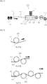
- Fig. 1 shows a tape-shaped prepreg production method according to an embodiment of the present invention, in which 100 denotes the entire setup for producing a tape-shaped prepreg.
- a plurality of bobbins 102 each having a continuous reinforcing fiber 101 wound thereon, are provided and the plurality of continuous reinforcing fibers 101 are sent out from the plurality of bobbins 102 while being guided by a yarn guide 103.
- the plurality of continuous reinforcing fibers 101 sent out continuously are then supplied with a molten thermoplastic resin composition 107 that is fed at a constant feeding rate from a feeder 105 filled with the thermoplastic resin and pass through a tank 104 having an inlet portion and an outlet portion.
- the plurality of continuous reinforcing fibers 101 introduced from the inlet portion of the tank can be impregnated with the thermoplastic resin composition 107 in a molten state while passing through the tank 104.
- the plurality of continuous reinforcing fibers 101 impregnated with the thermoplastic resin composition 107 are continuously pulled by the pulling force of the pull rolls 109, thereby passing through the outlet portion of the tank 104 and passing through a cooling mechanism 108 in which the thermoplastic resin composition 107 is cooled and solidified to form a tape-shaped prepreg 110 composed of the thermoplastic resin composition 107 and the continuous reinforcing fibers 101.
- the resulting tape-shaped prepreg 110 is preferably wound up on a winding roll 111 to form a roll.
- the width and thickness of the tape-shaped prepreg 110 are defined by the size of the outlet portion of the tank 104, and therefore, the size of the tape-shaped prepreg 110 can be controlled by changing the outlet size of the tank 104.
- the thermoplastic resin composition 107 filling the tank 104 may completely pass through the tank 104 together with the plurality of continuous reinforcing fibers 101, but in the case where the thermoplastic resin composition 107 in the tank 104 does not completely pass through it together with the plurality of continuous reinforcing fibers 101, the remaining part of the thermoplastic resin composition 107 left in the tank 104 can be discharged through the discharge port 106.
- the plurality of continuous reinforcing fibers are oriented unidirectionally in the traveling direction while the continuous reinforcing fibers pass through the tank. This allows the continuous reinforcing fibers in the resulting tape-shaped prepreg to be oriented in one direction.
- the orientation direction of the plurality of continuous reinforcing fibers is not particularly limited, but it is preferable that they are oriented in one direction because high workability is maintained during the production of the tape-shaped prepreg.
- roller-shaped members are used as cooling members of the cooling mechanism 108, it is preferable because friction does not occur between the rollers and accordingly, the tape-shaped prepreg is less likely to be damaged.
- roller-shaped members are used as cooling members of the cooling mechanism 108 will be described below with reference to Figs. 2 and 3 .
- Fig. 2 shows one embodiment of the cooling mechanism 108 illustrated in Fig. 1 and gives a schematic diagram of a cooling mechanism in which the tape-shaped prepreg 201 is held by roller-shaped members.
- cooling mechanisms of this type will be occasionally referred to as cooling mechanisms of a roller-shaped member type tape-shaped prepreg holding structure.
- the cooling mechanism 200 has a roller-shaped member type tape-shaped prepreg holding structure that contains only one roller-shaped member 202. After passing through the outlet of the tank 104, the tape-shaped prepreg 201 is allowed to travel with one side kept in contact with the roller-shaped member 202 so that the tape-shaped prepreg 201 is cooled and solidified.
- the cooling mechanism 203 has a roller-shaped member type tape-shaped prepreg holding structure that contains two roller-shaped members 202. After passing through the outlet of the tank 104, the tape-shaped prepreg 201 is allowed to travel with each side kept in contact with either of the roller-shaped members 202 so that the tape-shaped prepreg 201 is cooled and solidified.
- the cooling mechanism 204 has a roller-shaped member type tape-shaped prepreg holding structure that contains four roller-shaped members 202, in which the tape-shaped prepreg 201 is cooled in the same way as in 203.
- the temperature of the roller-shaped members contained in the cooling mechanism is controlled by, for example, passing water through them.
- Fig. 3 shows another embodiment of the cooling mechanism 108 illustrated in Fig. 1 and gives a schematic diagram of a cooling mechanism of a structure that contains one pair or a plurality of pairs of opposed roller-shaped members, each pair consisting of a roller-shaped member and another roller-shaped member located opposite thereto in the cooling mechanism, so that the tape-shaped prepreg can be interposed between them.
- cooling mechanisms of this type will be occasionally referred to as cooling mechanisms of a roller-shaped member type tape-shaped prepreg interposing structure.
- the cooling mechanism 300 has a roller-shaped member type tape-shaped prepreg interposing structure that contains two roller-shaped members 302.
- the cooling mechanism 303 has a roller-shaped member type tape-shaped prepreg interposing structure that contains four roller-shaped members 302, in which the tape-shaped prepreg 301 is cooled in the same way as in 300.
- the method for producing a tape-shaped prepreg according to the present invention it is also preferable to use one or a plurality of plate-shaped members as cooling members of the cooling mechanism 108. If plate-shaped members are used as cooling members of the cooling mechanism 108, it is preferable because the time of contact between the plate-shaped cooling members and the tape-shaped prepreg will be longer to realize more efficient cooling.
- Fig. 4 shows another embodiment of the cooling mechanism 108 illustrated in Fig. 1 and gives a schematic diagram of a cooling mechanism in which the tape-shaped prepreg 401 is in contact with plate-shaped members.
- cooling mechanisms of this type will be occasionally referred to as cooling mechanisms of a plate-shaped member type tape-shaped prepreg contact structure.
- the cooling mechanism 400 has a plate-shaped member type tape-shaped prepreg contact structure that contains only one plate-shaped member 402. After passing through the outlet of the tank 104, the tape-shaped prepreg 401 is allowed to travel with one side kept in contact with the plate-shaped member 402 so that the tape-shaped prepreg 401 is cooled and solidified.
- the cooling mechanism 403 has a plate-shaped member type tape-shaped prepreg contact structure that contains two plate-shaped members 402. After passing through the outlet of the tank 104, the tape-shaped prepreg 401 is allowed to travel between the plate-shaped members 402 with the two sides kept in contact with them so that the tape-shaped prepreg 401 is cooled and solidified.
- the cooling mechanism 404 has a plate-shaped member tape-shaped prepreg contact structure that contains four plate-shaped members 402, in which the tape-shaped prepreg 401 is cooled in the same way as in 403.
- roller-shaped members and plate-shaped members are used in combination as cooling members of the cooling mechanism 108, it is preferable because they serve to simultaneously realize the two good effects of a decreased friction achieved by the rollers and a lengthened time of contact with the tape-shaped prepreg achieved by the plate-shaped cooling members.
- Fig. 5 shows an embodiment of the cooling mechanism 108 illustrated in Fig. 1 and gives a schematic diagram of a cooling mechanism having a structure that contains a roller-shaped member(s) located opposite to a plate-shaped member(s) in the cooling mechanism 108 so that the tape-shaped prepreg is interposed between the roller-shaped member(s) and the plate-shaped member(s) of the cooling mechanism.
- a cooling mechanism of this type will be occasionally referred to as a cooling mechanism of the combined roller-shaped member and plate-shaped member type tape-shaped prepreg interposing structure.
- the cooling mechanism 500 illustrated therein contains one roller-shaped member 502 and one plate-shaped member 503.
- the tape-shaped prepreg 501 After passing through the outlet of the tank 104, the tape-shaped prepreg 501 is allowed to be interposed and passed between the roller-shaped member 502 and the plate-shaped member 503 with the two sides kept in contact with them so that the tape-shaped prepreg 501 is cooled and solidified.
- the cooling mechanism 504 illustrated therein contains two roller-shaped members 502 and two plate-shaped members 503, in which the tape-shaped prepreg 501 is cooled in the same way as in 500.
- the value of Pc/Qp [W•s/m 3 ] is in the range from 2.8 ⁇ 10 8 to 23.2 ⁇ 10 8 , more preferably from 4.7 ⁇ 10 8 to 20.4 ⁇ 10 8 , and still more preferably from 5.6 ⁇ 10 8 to 19.3 ⁇ 10 8 .
- the range may be between any of the upper limits and any of the lower limits.
- a large Pc/Qp value means that the heat absorbing capacity of the cooling mechanism is large relative to the volume of the tape-shaped prepreg passing through the cooling mechanism in one second to allow the tape-shaped prepreg to be cooled and solidified reliably, but if this Pc/Qp value exceeds 23.2 ⁇ 10 8 , a cooling mechanism having an unnecessarily large heat absorbing capacity will be required, leading to a facility of an increased size and an increased manufacturing cost.
- a small Pc/Qp value means that heat absorbing capacity of the cooling mechanism is so small relative to the volume of the tape-shaped prepreg passing through the cooling mechanism in one second that the tape-shaped prepreg cannot be cooled and solidified sufficiently, and if this Pc/Qp value is less than 2.8 ⁇ 10 8 , the tape-shaped prepreg will continue to cool and solidify even after passing through the cooling mechanism, consequently failing to obtain a tape-shaped prepreg of desired dimensions or resulting in a tape-shaped prepreg having a low surface smoothness.
- the heat absorbing capacity Pc[W] of the entire cooling mechanism is preferably 1.2 to 3.9 ⁇ 10 5 , more preferably 3.9 to 2.7 ⁇ 10 5 , and even more preferably 6.9 to 1.6 ⁇ 10 5 .
- the range may be between any of the upper limits and any of the lower limits.
- the cooling mechanism is installed for the purpose of cooling the tape-shaped prepreg, which is heated and produced by impregnating continuous reinforcing fibers with a thermoplastic resin in the tank and then being pulled out from the outlet portion of the tank, and in the case where there is no system intended for adjusting the temperature of the mechanism so that the temperature of the prepreg is allowed to decrease naturally as it passes through the mechanism, it is regarded that there is no such a cooling mechanism as referred to herein.
- Pc is 1.2 or more
- the cooling mechanism will have a high heat absorbing capacity, making it possible to obtain a tape-shaped prepreg having a high dimensional accuracy and surface smoothness.
- the cooling mechanism When Pc is 3.9 ⁇ 10 5 or less, it is possible to reduce the size of the cooling mechanism and simplify its structure. In terms of the heat absorbing capacity, it is preferable for the cooling mechanism to be designed on the basis of the type of the thermoplastic resin to be used and the temperature conditions and also on the basis of the volume of the tape-shaped prepreg passing through the cooling mechanism per second to meet the purpose of the present invention.
- the volume of the prepreg passing through the cooling mechanism per second Qp [m 3 /s] is preferably 4.2 ⁇ 10 -9 to 1.7 ⁇ 10 -4 , more preferably 8.3 ⁇ 10 -9 to 1.3 ⁇ 10 -4 , and still more preferably 1.3 ⁇ 10 -8 to 8.3 ⁇ 10 -5 .
- the range may be between any of the upper limits and any of the lower limits.
- the volume of the tape-shaped prepreg passing through the cooling mechanism in one second Qp [m 3 /s] can be calculated as the product of the speed of the tape-shaped prepreg passing through the cooling mechanism [m/s] multiplied by the outlet size (area [m 2 ]) of the tank.
- the cross-sectional shape of the cooling member contained in the cooling mechanism is not particularly limited, and it may be a roller shape or a plate shape.
- the cooling mechanism may have roller-shaped members alone; the cooling mechanism may have plate-shaped members alone; or the cooling mechanism may have a combination of roller-shaped members and plate-shaped members.
- the roller-shaped members may be supported by bearings etc. to permit spontaneous rotation, or they may be driven to rotate by motors or the like.
- roller-shaped members When roller-shaped members are used, it is expected that even if foreign matter enters the cooling mechanism, such foreign matter will be removed by the rotation of the roller as it passes between them.
- the surface area of each plate on which the tape-shaped prepreg passes is preferably flat, although the edge portion at the plate end from which the tape-shaped prepreg is introduced into the cooling mechanism may have a curved surface or a tapered surface.
- the area of contact of the tape-shaped prepreg with the cooling mechanism will be larger compared with the case where roller-shaped members are used, and accordingly, a high cooling and solidification effect can be realized using a small scale facility.
- the cooling members of the cooling mechanism used therefor preferably has an arithmetic average roughness (Ra) of 0.1 to 25.0 ⁇ m, more preferably 0.4 to 12.5 ⁇ m, and still more preferably 0.8 to 6.3 ⁇ m, as measured according to JIS B 0601: 2013, regardless of whether the members have a roller shape or a plate shape.
- the range may be between any of the upper limits and any of the lower limits.
- the cooling members of a cooling mechanism and the tape-shaped prepreg will have nearly equal Ra values or the Ra value of the tape-shaped prepreg will be 10 to 20 times as large as the Ra value of the cooling members of the cooling mechanism if the cooling mechanism has an appropriate degree of heat absorbing capacity and also if there is an appropriate degree of frictional force acting between the cooling mechanism and the tape-shaped prepreg that is passing through the cooling mechanism, and accordingly, it is preferable for the cooling members of the cooling mechanism to have an appropriately selected Ra value to suit the desired Ra value of the tape-shaped prepreg.
- the cooling members of the cooling mechanism used has a structure that is temperature-adjustable. If a plurality of cooling members exist in the cooling mechanism, it is preferable that each cooling member is temperature-adjustable independently, regardless of whether roller-shaped members or plate-shaped members are used in the cooling mechanism.
- the method and means to be used for adjusting the temperature of the cooling members is not particularly limited, and good examples include the method of flowing a fluid through the interior of the cooling members, the method of applying a fluid to the cooling members from the outside of the cooling members, and the method of fixing a device working as a heat source in each cooling member.
- the method of flowing a fluid through the interior of the cooling members is preferred because the structure of the cooling members can be so simple that temperature adjustment can be performed efficiently.
- the fluid to be flowed through the interior of the cooling members of the cooling mechanism is not particularly limited, and examples thereof include water, steam, air, oil, and antifreeze such as ethylene glycol.
- the cross-sectional shape is not particularly limited regardless of whether roller-shaped or plate-shaped members are used, and it may be circular or rectangular. If the fluid flow formed in the interior of the cooling members has a circular cross section, it is preferable because the structure of the cooling members can be simplified.
- the flow rate is preferably as larger as possible to allow the heat transferred from the tape-shaped prepreg to the cooling mechanism to be exchanged efficiently, although it is preferably adjusted so that the Pc/Qp ratio is stay within the range set forth for the present invention while meeting the constraint requirements of the facility.
- the cooling capacity depends on the size, number, set temperature, fluid flow rate of the cooling members of the cooling mechanism, and therefore, it is preferably designed so that a desired heat absorbing capacity is ensured while meeting constraint requirements such as the specifications and space of the facility.
- the size of the cooling members in particular, the contact length between the tape-shaped prepreg and the cooling members is nearly proportional to the cooling capacity, and it is desirable to design them based on calculations of the size to suit the cooling capacity.
- the shapes of the cooling members of the cooling mechanism to be used for the method for producing a tape-shaped prepreg according to the present invention are not particularly limited, but in the case of using a cooling mechanism having a structure in which a cooling member is located opposite to another cooling member to form a pairing shape, with the tape-shaped prepreg sandwiched between them, so that the tape-shaped prepreg is interposed between the cooling members that form a pairing shape, the structure is preferably one in which the distance between the cooling members sandwiching the tape-shaped prepreg can be adjusted as desired.
- the method to be used for setting the distance between the cooling members as desired is not particularly limited, and examples include the method of adjusting the position of the top or bottom dead center of an air cylinder or a hydraulic cylinder to a desired distance and the method of interposing a shim plate between the cooling members. If the distance between the cooling members can be set as desired, there are advantages such as high workability at the time of production preparation and adjustability of the degree of contact between the cooling members of the cooling mechanism and the tape-shaped prepreg. If the distance between the cooling members is too narrow, the tape-shaped prepreg will not be able to pass through the cooling mechanism. If the distance between the cooling members is too wide, the tape-shaped prepreg may fail to be in contact with the cooling mechanism and the tape-shaped prepreg will not cool and solidify in some cases.
- the shapes of the cooling members of the cooling mechanism to be used for the method for producing a tape-shaped prepreg according to the present invention are not particularly limited, but in the case of using a cooling mechanism having a structure in which a cooling member is located opposite to another cooling member to form a pairing shape, with the tape-shaped prepreg sandwiched between them, so that the tape-shaped prepreg is interposed between a pair of cooling members, the structure is preferably one in which the force applied to fix the cooling members at specified positions with a specified distance maintained between the cooling members can be adjusted as desired.
- the method to be used for fixing the cooling members at specified positions is not particularly limited, and an appropriate method may be adopted according to the fixing means used.
- the tape-shaped prepreg passing through the cooling mechanism after exiting the outlet of the tank may be either in a state in which it is continuous in the direction perpendicular to the traveling direction (i.e., only one tape-shaped prepreg is produced by making it travel alone) or in a divided state (i.e., a plurality of tape-shaped prepreg strips are produced by making them travel in parallel simultaneously).
- the surface of each cooling member coming in contact with the tape-shaped prepreg may be either uniform and flat, or irregular depending on the size of the tape-shaped prepreg, regardless of whether the cooling members of the cooling mechanism are roller-shaped or plate-shaped.
- the tape-shaped prepreg that is continuous in the direction perpendicular to the traveling direction of the tape-shaped prepreg is higher in productivity.
- the tape-shaped prepreg that is discontinuous in the direction perpendicular to the traveling direction of the tape-shaped prepreg is so higher in dimensional design freedom that they can meet a wide range of dimensional requirements of various cooling members.
- Measurement of specific gravity was performed using a specific gravity measuring device (ELECTRONIC DENSIMETER SD-200L, manufactured by Alfa Mirage Co., Ltd.).
- Fiber volume content % W 2 g / specific gravity of reinforcing fiber g / cm 3 / W 1 g / specific gravity of tape-shaped prepreg g / cm 3 ⁇ 100
- Resin volume content % W 1 ⁇ W 2 g / specific gravity of thermoplastic resin composition g / cm 3 / W 1 g / specific gravity of tape-shaped prepreg g / cm 3 ⁇ 100
- Void content % 100 ⁇ fiber volume content % ⁇ resin volume content %
- the thickness of a tape-shaped prepreg sample was measured at appropriately selected 15 different points using a micrometer and the arithmetic average of the measurements was calculated to represent the thickness of the tape-shaped prepreg.
- Two 300 mm long pieces of a tape-shaped prepreg were welded together along their long sides using a soldering iron, and it was rated as A when the operation was completed easily within 3 mites, rated as B when the operation required careful work and an operation time of 3 minutes or more, and rated as C when the operation involved difficulty. In Examples below, a sample rated as B or higher is judged to be acceptable.
- Bobbins 102 carrying reinforcing fibers 101 wound thereon were set as shown in Fig.1 , and the reinforcing fibers 101 were continuously sent out from the bobbins 102 through the yarn guide 103.
- the continuously supplied reinforcing fibers 101 were impregnated with a thermoplastic resin composition 107 that is fed at a constant feeding rate from a feeder 105 filled with the thermoplastic resin composition.
- the reinforcing fibers 101 impregnated with the thermoplastic resin composition 107 in the tank 104 were continuously drawn from a nozzle having a gap with a width of 50 mm and a thickness of 0.30 mm located downstream of the tank 104.
- the reinforcing fibers 101 were used in such a manner that their total cross-section accounts for 50% of the cross-section of the nozzle gap.
- the reinforcing fibers 101 pulled by the pull rolls 109 were cooled and solidified as they passed through a cooling mechanism 108, and wound by a winder 111 to provide a tape-shaped prepreg 110 having a fiber volume content of 50 vol%.
- the shape and number of the cooling members of the cooling mechanism were as described under (c-1). All samples had a surface roughness (Ra) of 0.2 ⁇ m.
- Cooling water was supplied to flow inside (c-1) and the Pc/Qp ratio, wherein Pc [W] is the heat absorbing capacity of the cooling mechanism and Qp [m 3 /s] is the volume of the tape-shaped prepreg passing through the cooling mechanism in one second, was 5.7 ⁇ 10 8 .
- the tape-shaped prepreg coming out from the outlet of the tank 104 was cooled as it passed between a pair of roller-shaped cooling members and then passed between another pair of roller-shaped cooling members. Results are shown in Tables 1-1.
- Example 1 Except that the nozzle of the tank 104 had a gap thickness of 0.15 mm, the same procedure as in Example 1 was carried out to provide a tape-shaped prepreg 110 having a different thickness. Results are shown in Tables 1-1.
- Example 1 Except that the nozzle of the tank 104 had a gap thickness of 0.20 mm, the same procedure as in Example 1 was carried out to provide a tape-shaped prepreg 110 having a different thickness. Results are shown in Tables 1-1.
- Example 1 Except that the nozzle of the tank 104 had a gap thickness of 0.50 mm, the same procedure as in Example 1 was carried out to provide a tape-shaped prepreg 110 having a different thickness. Results are shown in Tables 1-1.
- each roller-shaped cooling member used in the cooling mechanism was a cooling member having a surface roughness (Ra) of 12.0 ⁇ m
- the same procedure as in Example 1 was carried out to provide a tape-shaped prepreg 110 having a different surface roughness. Results are shown in Tables 1-1.
- Example 5 Except that the nozzle of the tank 104 had a gap thickness of 0.20 mm, the same procedure as in Example 5 was carried out to provide a tape-shaped prepreg 110 having a different thickness. Results are shown in Tables 1-1.
- Example 5 Except that the nozzle of the tank 104 had a gap thickness of 0.50 mm, the same procedure as in Example 5 was carried out to provide a tape-shaped prepreg 110 having a different thickness. Results are shown in Tables 1-1.
- Example 2 Except that the amount of the reinforcing fibers 101 used was such that their total cross-section accounted for 40% of the cross-section of the nozzle gap in the tank 104, the same procedure as in Example 1 was carried out to provide a tape-shaped prepreg 110 having a different fiber volume content. Results are shown in Tables 1-2.
- Example 2 Except that the amount of the reinforcing fibers 101 used was such that their total cross-section accounted for 60% of the cross-section of the nozzle gap in the tank 104, the same procedure as in Example 1 was carried out to provide a tape-shaped prepreg 110 having a different fiber volume content. Results are shown in Tables 1-2.
- Example 2 Except that the production rate was twice that in Example 1, the same procedure as in Example 1 was carried out to provide a tape-shaped prepreg 110 having a different void content. Results are shown in Tables 1-2.
- Example 11 Except that the nozzle of the tank 104 had a gap thickness of 0.15 mm, the same procedure as in Example 11 was carried out to provide a tape-shaped prepreg 110 having a different thickness. Results are shown in Tables 1-2.
- Example 1 Except that the nozzle of the tank 104 had a gap width of 10 mm and a gap thickness of 0.05 mm, the same procedure as in Example 1 was carried out to provide a tape-shaped prepreg 110 having a different width and a different thickness. Results are shown in Tables 1-3.
- Example 13 Except that the Pc/Qp ratio was 18.1 ⁇ 10 8 , the same procedure as in Example 13 was carried out to provide a tape-shaped prepreg 110. Results are shown in Tables 1-3.
- Example 2 Except that the nozzle of the tank 104 had a gap width of 300 mm, the same procedure as in Example 2 was carried out to provide a tape-shaped prepreg 110 having a different width and a different thickness. Results are shown in Tables 1-3.
- Example 15 Except that the Pc/Qp ratio was 18.1 ⁇ 10 8 , the same procedure as in Example 15 was carried out to provide a tape-shaped prepreg 110. Results are shown in Tables 1-3.
- Example 15 Except that the nozzle of the tank 104 had a gap thickness of 0.30 mm, the same procedure as in Example 15 was carried out to provide a tape-shaped prepreg 110 having a different width and a different thickness. Results are shown in Tables 1-3.
- Example 17 Except that the Pc/Qp ratio was 18.1 ⁇ 10 8 , the same procedure as in Example 17 was carried out to provide a tape-shaped prepreg 110. Results are shown in Tables 1-3.
- Example 21 Except that the Pc/Qp ratio was 18.1 ⁇ 10 8 , the same procedure as in Example 21 was carried out to provide a tape-shaped prepreg 110. Results are shown in Tables 2-1.
- Example 21 Except that the nozzle of the tank 104 had a gap thickness of 0.30 mm, the same procedure as in Example 21 was carried out to provide a tape-shaped prepreg 110 having a different width and a different thickness. Results are shown in Tables 2-1.
- Example 21 Except that the nozzle of the tank 104 had a gap width of 300 mm, the same procedure as in Example 21 was carried out to provide a tape-shaped prepreg 110 having a different width and a different thickness. Results are shown in Tables 2-2.
- Example 25 Except that the Pc/Qp ratio was 18.1 ⁇ 10 8 , the same procedure as in Example 25 was carried out to provide a tape-shaped prepreg 110. Results are shown in Tables 2-2.
- Example 25 Except that the nozzle of the tank 104 had a gap thickness of 0.30 mm, the same procedure as in Example 25 was carried out to provide a tape-shaped prepreg 110 having a different width and a different thickness. Results are shown in Tables 2-2.
- Example 27 Except that the Pc/Qp ratio was 18.1 ⁇ 10 8 , the same procedure as in Example 27 was carried out to provide a tape-shaped prepreg 110. Results are shown in Tables 2-2.
- Example 1 Example 2
- Example 3 Example 4
- Example 5 Example 6
- Example 7 Reinforcing fiber type a-1 a-1 a-1 a-1 a-1 a-1 a-1 a-1 a-1 Thermoplastic resin type b-1 b-1 b-1 b-1 b-1 b-1 b-1
- Members of cooling mechanism shape number c-1 c-1 c-1 c-1 c-1 c-1 c-1 Ra [ ⁇ m] 0.2 0.2 0.2 0.2 12.0 12.0 12.0
- Pc/Qp 5.7 ⁇ 10 8 5.7 ⁇ 10 8 5.7 ⁇ 10 8 5.7 ⁇ 10 8 5.7 ⁇ 10 8 5.7 ⁇ 10 8 5.7 ⁇ 10 8 5.7 ⁇ 10 8 5.7 ⁇ 10 8 5.7 ⁇ 10 8 Width of nozzle [mm] 50 50 50 50 50 50 50 50 50 50 50 50 50 50 Thickness of nozzle [mm] 0.30 0.15 0.20 0.50 0.30 0.20 0.50
- Fiber volume content (vol%) 50 50 50 50
- Example 8 Example 9 Example 10
- Example 11 Example 12 Reinforcing fiber type a-1 a-1 a-1 a-1 a-1 a-1 a-1 Thermoplastic resin type b-1 b-1 b-1 b-1 b-1 Members of cooling mechanism shape, number c-1 c-1 c-1 c-1 c-1 Ra [ ⁇ m] 0.2 0.2 0.2 0.2 Pc/Qp 5.7 ⁇ 10 8 5.7 ⁇ 10 8 5.7 ⁇ 10 8 18.1 ⁇ 10 8 18.1 ⁇ 10 8 Width of nozzle [mm] 50 50 50 50 50 50 50 50 Thickness of nozzle [mm] 0.30 0.30 0.30 0.30 0.15 Fiber volume content (vol%) 40 60 50 50 50 50 Void content (vol%) 1.4 2.4 5.5 2.3 1.3 Warpage rate (%) 2.4 1.0 1.8 0.9 0.7 Surface roughness of prepreg Ra [ ⁇ m] 3.8 4.5 6.1 4.0 3.9 Maximum cross-sectional height in waviness curve Wt [ ⁇ m] 42 43 46 35
Landscapes
- Chemical & Material Sciences (AREA)
- Engineering & Computer Science (AREA)
- Mechanical Engineering (AREA)
- Composite Materials (AREA)
- Materials Engineering (AREA)
- Polymers & Plastics (AREA)
- Health & Medical Sciences (AREA)
- Chemical Kinetics & Catalysis (AREA)
- Medicinal Chemistry (AREA)
- Manufacturing & Machinery (AREA)
- Organic Chemistry (AREA)
- Inorganic Chemistry (AREA)
- Textile Engineering (AREA)
- Reinforced Plastic Materials (AREA)
Applications Claiming Priority (3)
| Application Number | Priority Date | Filing Date | Title |
|---|---|---|---|
| JP2017245913 | 2017-12-22 | ||
| JP2017245914 | 2017-12-22 | ||
| PCT/JP2018/045826 WO2019124203A1 (fr) | 2017-12-22 | 2018-12-13 | Préimprégné en forme de bande et son procédé de production |
Publications (3)
| Publication Number | Publication Date |
|---|---|
| EP3730264A1 true EP3730264A1 (fr) | 2020-10-28 |
| EP3730264A4 EP3730264A4 (fr) | 2021-09-01 |
| EP3730264B1 EP3730264B1 (fr) | 2022-08-24 |
Family
ID=66994666
Family Applications (1)
| Application Number | Title | Priority Date | Filing Date |
|---|---|---|---|
| EP18892541.6A Active EP3730264B1 (fr) | 2017-12-22 | 2018-12-13 | Préimprégné en forme de bande et son procédé de production |
Country Status (6)
| Country | Link |
|---|---|
| US (1) | US11938655B2 (fr) |
| EP (1) | EP3730264B1 (fr) |
| JP (1) | JPWO2019124203A1 (fr) |
| KR (1) | KR102621342B1 (fr) |
| CN (1) | CN111491769B (fr) |
| WO (1) | WO2019124203A1 (fr) |
Families Citing this family (5)
| Publication number | Priority date | Publication date | Assignee | Title |
|---|---|---|---|---|
| US11938688B2 (en) * | 2018-12-18 | 2024-03-26 | Resonac Corporation | Laminate, printed wiring board, semiconductor package, and method for manufacturing laminate |
| EP4204482A1 (fr) * | 2020-08-28 | 2023-07-05 | Toray Advanced Composites | Bande ud à caractéristiques de traitement améliorées et surface rugueuse et procédé de production associé |
| WO2022043391A1 (fr) * | 2020-08-28 | 2022-03-03 | Toray Advanced Composites | Bande ud à caractéristiques de traitement améliorées et son procédé de production |
| CN112776218B (zh) * | 2021-01-29 | 2025-09-30 | 山东非金属材料研究所 | 一种导电微纳米材料改性预浸料连续化制备装置 |
| JP2022150747A (ja) * | 2021-03-26 | 2022-10-07 | 帝人株式会社 | プリプレグ、プリプレグの製造方法、スリットプリプレグ、積層基材及び繊維強化複合材料 |
Family Cites Families (33)
| Publication number | Priority date | Publication date | Assignee | Title |
|---|---|---|---|---|
| DE2239815C2 (de) | 1972-08-12 | 1983-02-10 | Bayer Ag, 5090 Leverkusen | 2-Alkylamino-dihydropyridine, Verfahren zu ihrer Herstellung sowie diese enthaltende Arzneimittel |
| JPH0598042A (ja) * | 1991-10-03 | 1993-04-20 | Toray Ind Inc | ポリ−フエニレンスルフイド樹脂含浸繊維シート |
| JPH0631821A (ja) * | 1992-07-14 | 1994-02-08 | Ube Ind Ltd | 熱可塑性複合材料の製造方法 |
| US5462618A (en) * | 1993-03-23 | 1995-10-31 | Bell Helicopter Textron Inc. | Continuous process of making unidirectional graphite fiber reinforced pultruded rods having minimal fiber waviness |
| DE69427258T2 (de) * | 1993-03-31 | 2001-12-06 | Toray Industries, Inc. | Mit harz imprägnierte faserplatte |
| JP4000253B2 (ja) * | 2001-11-05 | 2007-10-31 | 三菱レイヨン株式会社 | 担持シート付きプリプレグ、及びプリプレグ用担持シート |
| JP2004051660A (ja) * | 2002-07-16 | 2004-02-19 | Toray Ind Inc | プリプレグおよびその製造方法 |
| JP2004291558A (ja) | 2003-03-28 | 2004-10-21 | Toray Ind Inc | 繊維強化熱可塑性樹脂製射出成形品およびその製造方法 |
| JP2005161797A (ja) * | 2003-12-05 | 2005-06-23 | Toray Ind Inc | プリプレグの製造方法および製造装置 |
| JP2007076224A (ja) * | 2005-09-15 | 2007-03-29 | Toho Tenax Co Ltd | 炭素繊維強化熱可塑性樹脂テープの製造装置 |
| JP4781084B2 (ja) | 2005-10-25 | 2011-09-28 | 帝人テクノプロダクツ株式会社 | 炭素繊維強化熱可塑性樹脂テープ及びその製造方法 |
| GB0613834D0 (en) * | 2006-07-12 | 2006-08-23 | Hexcel Composites Ltd | Composite material assembly |
| EP2138530B1 (fr) * | 2007-03-20 | 2017-03-29 | Toray Industries, Inc. | Matériau à mouler, pré-imprégné, matériau composite renforcé en fibres, et procédé de production d'un matériau de base à mouler renforcé en fibres |
| JP2008246782A (ja) * | 2007-03-29 | 2008-10-16 | Teijin Techno Products Ltd | 繊維強化熱可塑性樹脂テープ製造装置及び繊維強化熱可塑性樹脂テープの製造方法 |
| GB2471319A (en) * | 2009-06-26 | 2010-12-29 | Hexcel Composites Ltd | Manufacturing composite materials containing conductive fibres |
| EP2589475B1 (fr) | 2010-06-30 | 2020-06-17 | Toray Industries, Inc. | Procédé et appareil pour la production d'un préimprégné en forme de feuille |
| US8551380B2 (en) * | 2010-11-12 | 2013-10-08 | The Boeing Company | Method of laying up prepreg plies on contoured tools using a deformable carrier film |
| US9074064B2 (en) * | 2010-12-13 | 2015-07-07 | Toray Industries, Inc. | Carbon fiber prepreg, method for producing same and carbon fiber reinforced composite material |
| US20130164498A1 (en) * | 2011-12-21 | 2013-06-27 | Adc Acquisition Company | Thermoplastic composite prepreg for automated fiber placement |
| JP5929270B2 (ja) * | 2012-02-07 | 2016-06-01 | 東レ株式会社 | プリプレグおよびその製造方法、スリットプリプレグ、炭素繊維強化複合材料 |
| CN104684975B (zh) * | 2012-09-28 | 2016-11-23 | 东丽株式会社 | 预浸料坯和碳纤维增强复合材料 |
| CN103847111B (zh) * | 2012-12-01 | 2016-05-11 | 北京化工大学 | 一种连续纤维增强热塑性树脂片材的成型方法 |
| FR3017329B1 (fr) | 2014-02-13 | 2016-07-29 | Arkema France | Procede de fabrication d'un materiau fibreux pre-impregne de polymere thermoplastique en lit fluidise |
| JP6384121B2 (ja) | 2014-05-23 | 2018-09-05 | 東レ株式会社 | プリプレグ及びその製造方法ならびに炭素繊維強化複合材料 |
| JP6423303B2 (ja) * | 2014-07-16 | 2018-11-14 | 株式会社神戸製鋼所 | 繊維強化熱可塑性樹脂テープの製造装置及び製造方法 |
| WO2016009735A1 (fr) | 2014-07-16 | 2016-01-21 | 株式会社神戸製鋼所 | Dispositif de fabrication et procédé de fabrication de bande de résine thermoplastique renforcée par des fibres |
| CN105619842A (zh) * | 2014-10-31 | 2016-06-01 | 林世平 | 连续纤维增强热塑性预浸带的二合一浸渍生产法及其设备 |
| ES2842278T3 (es) * | 2014-11-03 | 2021-07-13 | Cytec Ind Inc | Unión de materiales compuestos |
| JP6535218B2 (ja) | 2015-05-22 | 2019-06-26 | 株式会社神戸製鋼所 | テープ状プリプレグ及び繊維強化成形体 |
| JP6650228B2 (ja) * | 2015-08-17 | 2020-02-19 | 株式会社神戸製鋼所 | 繊維強化熱可塑性樹脂テープの製造装置及び製造方法 |
| CN106113531B (zh) * | 2016-06-30 | 2018-09-18 | 宁波华业材料科技有限公司 | 一种防卷翘cfrt单向带复合片材的生产工艺 |
| CN106626444A (zh) * | 2016-07-27 | 2017-05-10 | 山东极威新材料科技有限公司 | 一种连续纤维增强热塑性复合材料拉挤型材的生产工艺 |
| TWI848068B (zh) * | 2019-03-08 | 2024-07-11 | 日商Toto股份有限公司 | 具備釉藥層的物品及其製造方法 |
-
2018
- 2018-12-13 JP JP2019513859A patent/JPWO2019124203A1/ja active Pending
- 2018-12-13 CN CN201880081972.4A patent/CN111491769B/zh active Active
- 2018-12-13 EP EP18892541.6A patent/EP3730264B1/fr active Active
- 2018-12-13 US US16/772,502 patent/US11938655B2/en active Active
- 2018-12-13 WO PCT/JP2018/045826 patent/WO2019124203A1/fr not_active Ceased
- 2018-12-13 KR KR1020207018534A patent/KR102621342B1/ko active Active
Also Published As
| Publication number | Publication date |
|---|---|
| KR102621342B1 (ko) | 2024-01-08 |
| KR20200098551A (ko) | 2020-08-20 |
| EP3730264B1 (fr) | 2022-08-24 |
| EP3730264A4 (fr) | 2021-09-01 |
| US11938655B2 (en) | 2024-03-26 |
| JPWO2019124203A1 (ja) | 2020-10-22 |
| CN111491769B (zh) | 2022-07-22 |
| CN111491769A (zh) | 2020-08-04 |
| US20200385540A1 (en) | 2020-12-10 |
| WO2019124203A1 (fr) | 2019-06-27 |
Similar Documents
| Publication | Publication Date | Title |
|---|---|---|
| EP3730264B1 (fr) | Préimprégné en forme de bande et son procédé de production | |
| EP3656807B1 (fr) | Préimprégné sous forme de bande à orientation unidirectionnelle, et article moulé à partir de celui-ci | |
| JP6451891B1 (ja) | 塗工装置およびシート状物の製造装置 | |
| JP7140131B2 (ja) | 離型シート付き多層構造プリプレグ、プリプレグロール、プリプレグテープおよび複合材料 | |
| EP2871202A1 (fr) | Base composite | |
| KR102300301B1 (ko) | 도포액 함침 강화 섬유 패브릭, 시트상 일체물, 프리프레그, 프리프레그 테이프 및 섬유 강화 복합 재료의 제조 방법 | |
| JP7243629B2 (ja) | プリプレグの製造方法および製造装置 | |
| US12172341B2 (en) | Method of producing thermoplastic resin-impregnated sheet-shaped reinforcing fiber bundle | |
| KR20200057111A (ko) | 섬유 강화 수지 재료 성형체, 섬유 강화 수지 재료 성형체의 제조 방법 및 섬유 강화 수지 재료의 제조 방법 | |
| EP3744768B1 (fr) | Mat de fibres de renforcement, et matériau de moulage de résine renforcé par des fibres et procédé de production associé | |
| EP3842202B1 (fr) | Procédé de production d'un préimprégné, ruban préimprégné et materiau composite renforcé par des fibres, et dispositif de production d'un préimprégné | |
| JP3830307B2 (ja) | 熱可塑性樹脂を含浸した成形材料の製造方法 | |
| EP3778200A1 (fr) | Article moulé de matériau composite et son procédé de fabrication | |
| JP2020028844A (ja) | 塗液含浸強化繊維シートおよびシート状一体物の製造方法、塗工装置 | |
| JP2018104537A (ja) | 基材 | |
| JP7676771B2 (ja) | 成型体の製造方法、およびフィラメントワインディング装置 | |
| JP2020029015A (ja) | プリプレグ、シート状一体物の製造装置および製造方法 | |
| JP2020029013A (ja) | プリプレグおよびシート状一体物の製造方法、塗工装置 | |
| JP2020029014A (ja) | プリプレグおよびシート状一体物の製造方法、塗工装置 | |
| JP2020029016A (ja) | プリプレグ、プリプレグテープおよび繊維強化複合材料の製造方法、プリプレグ製造装置 |
Legal Events
| Date | Code | Title | Description |
|---|---|---|---|
| STAA | Information on the status of an ep patent application or granted ep patent |
Free format text: STATUS: THE INTERNATIONAL PUBLICATION HAS BEEN MADE |
|
| PUAI | Public reference made under article 153(3) epc to a published international application that has entered the european phase |
Free format text: ORIGINAL CODE: 0009012 |
|
| STAA | Information on the status of an ep patent application or granted ep patent |
Free format text: STATUS: REQUEST FOR EXAMINATION WAS MADE |
|
| 17P | Request for examination filed |
Effective date: 20200608 |
|
| AK | Designated contracting states |
Kind code of ref document: A1 Designated state(s): AL AT BE BG CH CY CZ DE DK EE ES FI FR GB GR HR HU IE IS IT LI LT LU LV MC MK MT NL NO PL PT RO RS SE SI SK SM TR |
|
| AX | Request for extension of the european patent |
Extension state: BA ME |
|
| DAV | Request for validation of the european patent (deleted) | ||
| DAX | Request for extension of the european patent (deleted) | ||
| REG | Reference to a national code |
Ref country code: DE Ref legal event code: R079 Ref document number: 602018039859 Country of ref document: DE Free format text: PREVIOUS MAIN CLASS: B29B0015100000 Ipc: B29B0015120000 |
|
| A4 | Supplementary search report drawn up and despatched |
Effective date: 20210729 |
|
| RIC1 | Information provided on ipc code assigned before grant |
Ipc: B29B 15/12 20060101AFI20210723BHEP Ipc: B29C 70/20 20060101ALI20210723BHEP Ipc: B29C 70/52 20060101ALI20210723BHEP Ipc: B29K 105/08 20060101ALI20210723BHEP Ipc: B29K 105/10 20060101ALI20210723BHEP |
|
| GRAP | Despatch of communication of intention to grant a patent |
Free format text: ORIGINAL CODE: EPIDOSNIGR1 |
|
| STAA | Information on the status of an ep patent application or granted ep patent |
Free format text: STATUS: GRANT OF PATENT IS INTENDED |
|
| INTG | Intention to grant announced |
Effective date: 20220323 |
|
| GRAS | Grant fee paid |
Free format text: ORIGINAL CODE: EPIDOSNIGR3 |
|
| GRAA | (expected) grant |
Free format text: ORIGINAL CODE: 0009210 |
|
| STAA | Information on the status of an ep patent application or granted ep patent |
Free format text: STATUS: THE PATENT HAS BEEN GRANTED |
|
| AK | Designated contracting states |
Kind code of ref document: B1 Designated state(s): AL AT BE BG CH CY CZ DE DK EE ES FI FR GB GR HR HU IE IS IT LI LT LU LV MC MK MT NL NO PL PT RO RS SE SI SK SM TR |
|
| REG | Reference to a national code |
Ref country code: CH Ref legal event code: EP |
|
| REG | Reference to a national code |
Ref country code: DE Ref legal event code: R096 Ref document number: 602018039859 Country of ref document: DE |
|
| REG | Reference to a national code |
Ref country code: IE Ref legal event code: FG4D |
|
| REG | Reference to a national code |
Ref country code: AT Ref legal event code: REF Ref document number: 1513346 Country of ref document: AT Kind code of ref document: T Effective date: 20220915 |
|
| REG | Reference to a national code |
Ref country code: NL Ref legal event code: FP |
|
| REG | Reference to a national code |
Ref country code: LT Ref legal event code: MG9D |
|
| PG25 | Lapsed in a contracting state [announced via postgrant information from national office to epo] |
Ref country code: SE Free format text: LAPSE BECAUSE OF FAILURE TO SUBMIT A TRANSLATION OF THE DESCRIPTION OR TO PAY THE FEE WITHIN THE PRESCRIBED TIME-LIMIT Effective date: 20220824 Ref country code: RS Free format text: LAPSE BECAUSE OF FAILURE TO SUBMIT A TRANSLATION OF THE DESCRIPTION OR TO PAY THE FEE WITHIN THE PRESCRIBED TIME-LIMIT Effective date: 20220824 Ref country code: PT Free format text: LAPSE BECAUSE OF FAILURE TO SUBMIT A TRANSLATION OF THE DESCRIPTION OR TO PAY THE FEE WITHIN THE PRESCRIBED TIME-LIMIT Effective date: 20221226 Ref country code: NO Free format text: LAPSE BECAUSE OF FAILURE TO SUBMIT A TRANSLATION OF THE DESCRIPTION OR TO PAY THE FEE WITHIN THE PRESCRIBED TIME-LIMIT Effective date: 20221124 Ref country code: LV Free format text: LAPSE BECAUSE OF FAILURE TO SUBMIT A TRANSLATION OF THE DESCRIPTION OR TO PAY THE FEE WITHIN THE PRESCRIBED TIME-LIMIT Effective date: 20220824 Ref country code: LT Free format text: LAPSE BECAUSE OF FAILURE TO SUBMIT A TRANSLATION OF THE DESCRIPTION OR TO PAY THE FEE WITHIN THE PRESCRIBED TIME-LIMIT Effective date: 20220824 Ref country code: FI Free format text: LAPSE BECAUSE OF FAILURE TO SUBMIT A TRANSLATION OF THE DESCRIPTION OR TO PAY THE FEE WITHIN THE PRESCRIBED TIME-LIMIT Effective date: 20220824 |
|
| REG | Reference to a national code |
Ref country code: AT Ref legal event code: MK05 Ref document number: 1513346 Country of ref document: AT Kind code of ref document: T Effective date: 20220824 |
|
| PG25 | Lapsed in a contracting state [announced via postgrant information from national office to epo] |
Ref country code: PL Free format text: LAPSE BECAUSE OF FAILURE TO SUBMIT A TRANSLATION OF THE DESCRIPTION OR TO PAY THE FEE WITHIN THE PRESCRIBED TIME-LIMIT Effective date: 20220824 Ref country code: IS Free format text: LAPSE BECAUSE OF FAILURE TO SUBMIT A TRANSLATION OF THE DESCRIPTION OR TO PAY THE FEE WITHIN THE PRESCRIBED TIME-LIMIT Effective date: 20221224 Ref country code: HR Free format text: LAPSE BECAUSE OF FAILURE TO SUBMIT A TRANSLATION OF THE DESCRIPTION OR TO PAY THE FEE WITHIN THE PRESCRIBED TIME-LIMIT Effective date: 20220824 Ref country code: GR Free format text: LAPSE BECAUSE OF FAILURE TO SUBMIT A TRANSLATION OF THE DESCRIPTION OR TO PAY THE FEE WITHIN THE PRESCRIBED TIME-LIMIT Effective date: 20221125 |
|
| PG25 | Lapsed in a contracting state [announced via postgrant information from national office to epo] |
Ref country code: SM Free format text: LAPSE BECAUSE OF FAILURE TO SUBMIT A TRANSLATION OF THE DESCRIPTION OR TO PAY THE FEE WITHIN THE PRESCRIBED TIME-LIMIT Effective date: 20220824 Ref country code: RO Free format text: LAPSE BECAUSE OF FAILURE TO SUBMIT A TRANSLATION OF THE DESCRIPTION OR TO PAY THE FEE WITHIN THE PRESCRIBED TIME-LIMIT Effective date: 20220824 Ref country code: ES Free format text: LAPSE BECAUSE OF FAILURE TO SUBMIT A TRANSLATION OF THE DESCRIPTION OR TO PAY THE FEE WITHIN THE PRESCRIBED TIME-LIMIT Effective date: 20220824 Ref country code: DK Free format text: LAPSE BECAUSE OF FAILURE TO SUBMIT A TRANSLATION OF THE DESCRIPTION OR TO PAY THE FEE WITHIN THE PRESCRIBED TIME-LIMIT Effective date: 20220824 Ref country code: CZ Free format text: LAPSE BECAUSE OF FAILURE TO SUBMIT A TRANSLATION OF THE DESCRIPTION OR TO PAY THE FEE WITHIN THE PRESCRIBED TIME-LIMIT Effective date: 20220824 Ref country code: AT Free format text: LAPSE BECAUSE OF FAILURE TO SUBMIT A TRANSLATION OF THE DESCRIPTION OR TO PAY THE FEE WITHIN THE PRESCRIBED TIME-LIMIT Effective date: 20220824 |
|
| REG | Reference to a national code |
Ref country code: DE Ref legal event code: R026 Ref document number: 602018039859 Country of ref document: DE |
|
| PLBI | Opposition filed |
Free format text: ORIGINAL CODE: 0009260 |
|
| PG25 | Lapsed in a contracting state [announced via postgrant information from national office to epo] |
Ref country code: SK Free format text: LAPSE BECAUSE OF FAILURE TO SUBMIT A TRANSLATION OF THE DESCRIPTION OR TO PAY THE FEE WITHIN THE PRESCRIBED TIME-LIMIT Effective date: 20220824 Ref country code: EE Free format text: LAPSE BECAUSE OF FAILURE TO SUBMIT A TRANSLATION OF THE DESCRIPTION OR TO PAY THE FEE WITHIN THE PRESCRIBED TIME-LIMIT Effective date: 20220824 |
|
| PLAX | Notice of opposition and request to file observation + time limit sent |
Free format text: ORIGINAL CODE: EPIDOSNOBS2 |
|
| P01 | Opt-out of the competence of the unified patent court (upc) registered |
Effective date: 20230515 |
|
| 26 | Opposition filed |
Opponent name: VICTREX MANUFACTURING LIMITED Effective date: 20230523 |
|
| PG25 | Lapsed in a contracting state [announced via postgrant information from national office to epo] |
Ref country code: AL Free format text: LAPSE BECAUSE OF FAILURE TO SUBMIT A TRANSLATION OF THE DESCRIPTION OR TO PAY THE FEE WITHIN THE PRESCRIBED TIME-LIMIT Effective date: 20220824 |
|
| REG | Reference to a national code |
Ref country code: CH Ref legal event code: PL |
|
| REG | Reference to a national code |
Ref country code: BE Ref legal event code: MM Effective date: 20221231 |
|
| PG25 | Lapsed in a contracting state [announced via postgrant information from national office to epo] |
Ref country code: SI Free format text: LAPSE BECAUSE OF FAILURE TO SUBMIT A TRANSLATION OF THE DESCRIPTION OR TO PAY THE FEE WITHIN THE PRESCRIBED TIME-LIMIT Effective date: 20220824 Ref country code: LU Free format text: LAPSE BECAUSE OF NON-PAYMENT OF DUE FEES Effective date: 20221213 |
|
| PLBB | Reply of patent proprietor to notice(s) of opposition received |
Free format text: ORIGINAL CODE: EPIDOSNOBS3 |
|
| PG25 | Lapsed in a contracting state [announced via postgrant information from national office to epo] |
Ref country code: LI Free format text: LAPSE BECAUSE OF NON-PAYMENT OF DUE FEES Effective date: 20221231 Ref country code: IE Free format text: LAPSE BECAUSE OF NON-PAYMENT OF DUE FEES Effective date: 20221213 Ref country code: CH Free format text: LAPSE BECAUSE OF NON-PAYMENT OF DUE FEES Effective date: 20221231 |
|
| PLAB | Opposition data, opponent's data or that of the opponent's representative modified |
Free format text: ORIGINAL CODE: 0009299OPPO |
|
| PG25 | Lapsed in a contracting state [announced via postgrant information from national office to epo] |
Ref country code: BE Free format text: LAPSE BECAUSE OF NON-PAYMENT OF DUE FEES Effective date: 20221231 |
|
| R26 | Opposition filed (corrected) |
Opponent name: VICTREX MANUFACTURING LIMITED Effective date: 20230523 |
|
| PLAB | Opposition data, opponent's data or that of the opponent's representative modified |
Free format text: ORIGINAL CODE: 0009299OPPO |
|
| R26 | Opposition filed (corrected) |
Opponent name: VICTREX MANUFACTURING LIMITED Effective date: 20230523 |
|
| PG25 | Lapsed in a contracting state [announced via postgrant information from national office to epo] |
Ref country code: CY Free format text: LAPSE BECAUSE OF FAILURE TO SUBMIT A TRANSLATION OF THE DESCRIPTION OR TO PAY THE FEE WITHIN THE PRESCRIBED TIME-LIMIT Effective date: 20220824 |
|
| PG25 | Lapsed in a contracting state [announced via postgrant information from national office to epo] |
Ref country code: MK Free format text: LAPSE BECAUSE OF FAILURE TO SUBMIT A TRANSLATION OF THE DESCRIPTION OR TO PAY THE FEE WITHIN THE PRESCRIBED TIME-LIMIT Effective date: 20220824 Ref country code: IT Free format text: LAPSE BECAUSE OF FAILURE TO SUBMIT A TRANSLATION OF THE DESCRIPTION OR TO PAY THE FEE WITHIN THE PRESCRIBED TIME-LIMIT Effective date: 20220824 Ref country code: HU Free format text: LAPSE BECAUSE OF FAILURE TO SUBMIT A TRANSLATION OF THE DESCRIPTION OR TO PAY THE FEE WITHIN THE PRESCRIBED TIME-LIMIT; INVALID AB INITIO Effective date: 20181213 |
|
| PG25 | Lapsed in a contracting state [announced via postgrant information from national office to epo] |
Ref country code: MC Free format text: LAPSE BECAUSE OF FAILURE TO SUBMIT A TRANSLATION OF THE DESCRIPTION OR TO PAY THE FEE WITHIN THE PRESCRIBED TIME-LIMIT Effective date: 20220824 |
|
| PG25 | Lapsed in a contracting state [announced via postgrant information from national office to epo] |
Ref country code: TR Free format text: LAPSE BECAUSE OF FAILURE TO SUBMIT A TRANSLATION OF THE DESCRIPTION OR TO PAY THE FEE WITHIN THE PRESCRIBED TIME-LIMIT Effective date: 20220824 Ref country code: MC Free format text: LAPSE BECAUSE OF FAILURE TO SUBMIT A TRANSLATION OF THE DESCRIPTION OR TO PAY THE FEE WITHIN THE PRESCRIBED TIME-LIMIT Effective date: 20220824 |
|
| PLAB | Opposition data, opponent's data or that of the opponent's representative modified |
Free format text: ORIGINAL CODE: 0009299OPPO |
|
| PG25 | Lapsed in a contracting state [announced via postgrant information from national office to epo] |
Ref country code: BG Free format text: LAPSE BECAUSE OF FAILURE TO SUBMIT A TRANSLATION OF THE DESCRIPTION OR TO PAY THE FEE WITHIN THE PRESCRIBED TIME-LIMIT Effective date: 20220824 |
|
| R26 | Opposition filed (corrected) |
Opponent name: VICTREX MANUFACTURING LIMITED Effective date: 20230523 |
|
| PG25 | Lapsed in a contracting state [announced via postgrant information from national office to epo] |
Ref country code: MT Free format text: LAPSE BECAUSE OF FAILURE TO SUBMIT A TRANSLATION OF THE DESCRIPTION OR TO PAY THE FEE WITHIN THE PRESCRIBED TIME-LIMIT Effective date: 20220824 |
|
| APBP | Date of receipt of notice of appeal recorded |
Free format text: ORIGINAL CODE: EPIDOSNNOA2O |
|
| APAH | Appeal reference modified |
Free format text: ORIGINAL CODE: EPIDOSCREFNO |
|
| APBP | Date of receipt of notice of appeal recorded |
Free format text: ORIGINAL CODE: EPIDOSNNOA2O |
|
| APAW | Appeal reference deleted |
Free format text: ORIGINAL CODE: EPIDOSDREFNO |
|
| APBQ | Date of receipt of statement of grounds of appeal recorded |
Free format text: ORIGINAL CODE: EPIDOSNNOA3O |
|
| PGFP | Annual fee paid to national office [announced via postgrant information from national office to epo] |
Ref country code: NL Payment date: 20251112 Year of fee payment: 8 |
|
| PGFP | Annual fee paid to national office [announced via postgrant information from national office to epo] |
Ref country code: DE Payment date: 20251028 Year of fee payment: 8 |
|
| PGFP | Annual fee paid to national office [announced via postgrant information from national office to epo] |
Ref country code: GB Payment date: 20251030 Year of fee payment: 8 |
|
| PGFP | Annual fee paid to national office [announced via postgrant information from national office to epo] |
Ref country code: FR Payment date: 20251110 Year of fee payment: 8 |