EP3730331B1 - Procédé et dispositif pour contrôler une assistance à la conduite - Google Patents
Procédé et dispositif pour contrôler une assistance à la conduite Download PDFInfo
- Publication number
- EP3730331B1 EP3730331B1 EP19171430.2A EP19171430A EP3730331B1 EP 3730331 B1 EP3730331 B1 EP 3730331B1 EP 19171430 A EP19171430 A EP 19171430A EP 3730331 B1 EP3730331 B1 EP 3730331B1
- Authority
- EP
- European Patent Office
- Prior art keywords
- driver
- parameter
- attention
- reaction
- vehicle
- Prior art date
- Legal status (The legal status is an assumption and is not a legal conclusion. Google has not performed a legal analysis and makes no representation as to the accuracy of the status listed.)
- Active
Links
Images


Classifications
-
- B—PERFORMING OPERATIONS; TRANSPORTING
- B60—VEHICLES IN GENERAL
- B60K—ARRANGEMENT OR MOUNTING OF PROPULSION UNITS OR OF TRANSMISSIONS IN VEHICLES; ARRANGEMENT OR MOUNTING OF PLURAL DIVERSE PRIME-MOVERS IN VEHICLES; AUXILIARY DRIVES FOR VEHICLES; INSTRUMENTATION OR DASHBOARDS FOR VEHICLES; ARRANGEMENTS IN CONNECTION WITH COOLING, AIR INTAKE, GAS EXHAUST OR FUEL SUPPLY OF PROPULSION UNITS IN VEHICLES
- B60K28/00—Safety devices for propulsion-unit control, specially adapted for, or arranged in, vehicles, e.g. preventing fuel supply or ignition in the event of potentially dangerous conditions
- B60K28/02—Safety devices for propulsion-unit control, specially adapted for, or arranged in, vehicles, e.g. preventing fuel supply or ignition in the event of potentially dangerous conditions responsive to conditions relating to the driver
- B60K28/06—Safety devices for propulsion-unit control, specially adapted for, or arranged in, vehicles, e.g. preventing fuel supply or ignition in the event of potentially dangerous conditions responsive to conditions relating to the driver responsive to incapacity of driver
-
- B—PERFORMING OPERATIONS; TRANSPORTING
- B60—VEHICLES IN GENERAL
- B60W—CONJOINT CONTROL OF VEHICLE SUB-UNITS OF DIFFERENT TYPE OR DIFFERENT FUNCTION; CONTROL SYSTEMS SPECIALLY ADAPTED FOR HYBRID VEHICLES; ROAD VEHICLE DRIVE CONTROL SYSTEMS FOR PURPOSES NOT RELATED TO THE CONTROL OF A PARTICULAR SUB-UNIT
- B60W40/00—Estimation or calculation of non-directly measurable driving parameters for road vehicle drive control systems not related to the control of a particular sub unit, e.g. by using mathematical models
- B60W40/08—Estimation or calculation of non-directly measurable driving parameters for road vehicle drive control systems not related to the control of a particular sub unit, e.g. by using mathematical models related to drivers or passengers
-
- B—PERFORMING OPERATIONS; TRANSPORTING
- B60—VEHICLES IN GENERAL
- B60K—ARRANGEMENT OR MOUNTING OF PROPULSION UNITS OR OF TRANSMISSIONS IN VEHICLES; ARRANGEMENT OR MOUNTING OF PLURAL DIVERSE PRIME-MOVERS IN VEHICLES; AUXILIARY DRIVES FOR VEHICLES; INSTRUMENTATION OR DASHBOARDS FOR VEHICLES; ARRANGEMENTS IN CONNECTION WITH COOLING, AIR INTAKE, GAS EXHAUST OR FUEL SUPPLY OF PROPULSION UNITS IN VEHICLES
- B60K28/00—Safety devices for propulsion-unit control, specially adapted for, or arranged in, vehicles, e.g. preventing fuel supply or ignition in the event of potentially dangerous conditions
- B60K28/02—Safety devices for propulsion-unit control, specially adapted for, or arranged in, vehicles, e.g. preventing fuel supply or ignition in the event of potentially dangerous conditions responsive to conditions relating to the driver
- B60K28/06—Safety devices for propulsion-unit control, specially adapted for, or arranged in, vehicles, e.g. preventing fuel supply or ignition in the event of potentially dangerous conditions responsive to conditions relating to the driver responsive to incapacity of driver
- B60K28/066—Safety devices for propulsion-unit control, specially adapted for, or arranged in, vehicles, e.g. preventing fuel supply or ignition in the event of potentially dangerous conditions responsive to conditions relating to the driver responsive to incapacity of driver actuating a signalling device
-
- B—PERFORMING OPERATIONS; TRANSPORTING
- B60—VEHICLES IN GENERAL
- B60W—CONJOINT CONTROL OF VEHICLE SUB-UNITS OF DIFFERENT TYPE OR DIFFERENT FUNCTION; CONTROL SYSTEMS SPECIALLY ADAPTED FOR HYBRID VEHICLES; ROAD VEHICLE DRIVE CONTROL SYSTEMS FOR PURPOSES NOT RELATED TO THE CONTROL OF A PARTICULAR SUB-UNIT
- B60W40/00—Estimation or calculation of non-directly measurable driving parameters for road vehicle drive control systems not related to the control of a particular sub unit, e.g. by using mathematical models
-
- B—PERFORMING OPERATIONS; TRANSPORTING
- B60—VEHICLES IN GENERAL
- B60W—CONJOINT CONTROL OF VEHICLE SUB-UNITS OF DIFFERENT TYPE OR DIFFERENT FUNCTION; CONTROL SYSTEMS SPECIALLY ADAPTED FOR HYBRID VEHICLES; ROAD VEHICLE DRIVE CONTROL SYSTEMS FOR PURPOSES NOT RELATED TO THE CONTROL OF A PARTICULAR SUB-UNIT
- B60W50/00—Details of control systems for road vehicle drive control not related to the control of a particular sub-unit, e.g. process diagnostic or vehicle driver interfaces
- B60W50/02—Ensuring safety in case of control system failures, e.g. by diagnosing, circumventing or fixing failures
- B60W50/0205—Diagnosing or detecting failures; Failure detection models
-
- B—PERFORMING OPERATIONS; TRANSPORTING
- B60—VEHICLES IN GENERAL
- B60W—CONJOINT CONTROL OF VEHICLE SUB-UNITS OF DIFFERENT TYPE OR DIFFERENT FUNCTION; CONTROL SYSTEMS SPECIALLY ADAPTED FOR HYBRID VEHICLES; ROAD VEHICLE DRIVE CONTROL SYSTEMS FOR PURPOSES NOT RELATED TO THE CONTROL OF A PARTICULAR SUB-UNIT
- B60W50/00—Details of control systems for road vehicle drive control not related to the control of a particular sub-unit, e.g. process diagnostic or vehicle driver interfaces
- B60W50/08—Interaction between the driver and the control system
- B60W50/14—Means for informing the driver, warning the driver or prompting a driver intervention
-
- B—PERFORMING OPERATIONS; TRANSPORTING
- B60—VEHICLES IN GENERAL
- B60W—CONJOINT CONTROL OF VEHICLE SUB-UNITS OF DIFFERENT TYPE OR DIFFERENT FUNCTION; CONTROL SYSTEMS SPECIALLY ADAPTED FOR HYBRID VEHICLES; ROAD VEHICLE DRIVE CONTROL SYSTEMS FOR PURPOSES NOT RELATED TO THE CONTROL OF A PARTICULAR SUB-UNIT
- B60W60/00—Drive control systems specially adapted for autonomous road vehicles
- B60W60/001—Planning or execution of driving tasks
- B60W60/0013—Planning or execution of driving tasks specially adapted for occupant comfort
-
- B—PERFORMING OPERATIONS; TRANSPORTING
- B60—VEHICLES IN GENERAL
- B60W—CONJOINT CONTROL OF VEHICLE SUB-UNITS OF DIFFERENT TYPE OR DIFFERENT FUNCTION; CONTROL SYSTEMS SPECIALLY ADAPTED FOR HYBRID VEHICLES; ROAD VEHICLE DRIVE CONTROL SYSTEMS FOR PURPOSES NOT RELATED TO THE CONTROL OF A PARTICULAR SUB-UNIT
- B60W40/00—Estimation or calculation of non-directly measurable driving parameters for road vehicle drive control systems not related to the control of a particular sub unit, e.g. by using mathematical models
- B60W40/08—Estimation or calculation of non-directly measurable driving parameters for road vehicle drive control systems not related to the control of a particular sub unit, e.g. by using mathematical models related to drivers or passengers
- B60W2040/0818—Inactivity or incapacity of driver
- B60W2040/0827—Inactivity or incapacity of driver due to sleepiness
-
- B—PERFORMING OPERATIONS; TRANSPORTING
- B60—VEHICLES IN GENERAL
- B60W—CONJOINT CONTROL OF VEHICLE SUB-UNITS OF DIFFERENT TYPE OR DIFFERENT FUNCTION; CONTROL SYSTEMS SPECIALLY ADAPTED FOR HYBRID VEHICLES; ROAD VEHICLE DRIVE CONTROL SYSTEMS FOR PURPOSES NOT RELATED TO THE CONTROL OF A PARTICULAR SUB-UNIT
- B60W40/00—Estimation or calculation of non-directly measurable driving parameters for road vehicle drive control systems not related to the control of a particular sub unit, e.g. by using mathematical models
- B60W40/08—Estimation or calculation of non-directly measurable driving parameters for road vehicle drive control systems not related to the control of a particular sub unit, e.g. by using mathematical models related to drivers or passengers
- B60W2040/0818—Inactivity or incapacity of driver
- B60W2040/0863—Inactivity or incapacity of driver due to erroneous selection or response of the driver
-
- B—PERFORMING OPERATIONS; TRANSPORTING
- B60—VEHICLES IN GENERAL
- B60W—CONJOINT CONTROL OF VEHICLE SUB-UNITS OF DIFFERENT TYPE OR DIFFERENT FUNCTION; CONTROL SYSTEMS SPECIALLY ADAPTED FOR HYBRID VEHICLES; ROAD VEHICLE DRIVE CONTROL SYSTEMS FOR PURPOSES NOT RELATED TO THE CONTROL OF A PARTICULAR SUB-UNIT
- B60W40/00—Estimation or calculation of non-directly measurable driving parameters for road vehicle drive control systems not related to the control of a particular sub unit, e.g. by using mathematical models
- B60W40/08—Estimation or calculation of non-directly measurable driving parameters for road vehicle drive control systems not related to the control of a particular sub unit, e.g. by using mathematical models related to drivers or passengers
- B60W2040/0872—Driver physiology
-
- B—PERFORMING OPERATIONS; TRANSPORTING
- B60—VEHICLES IN GENERAL
- B60W—CONJOINT CONTROL OF VEHICLE SUB-UNITS OF DIFFERENT TYPE OR DIFFERENT FUNCTION; CONTROL SYSTEMS SPECIALLY ADAPTED FOR HYBRID VEHICLES; ROAD VEHICLE DRIVE CONTROL SYSTEMS FOR PURPOSES NOT RELATED TO THE CONTROL OF A PARTICULAR SUB-UNIT
- B60W50/00—Details of control systems for road vehicle drive control not related to the control of a particular sub-unit, e.g. process diagnostic or vehicle driver interfaces
- B60W50/02—Ensuring safety in case of control system failures, e.g. by diagnosing, circumventing or fixing failures
- B60W50/0205—Diagnosing or detecting failures; Failure detection models
- B60W2050/0215—Sensor drifts or sensor failures
-
- B—PERFORMING OPERATIONS; TRANSPORTING
- B60—VEHICLES IN GENERAL
- B60W—CONJOINT CONTROL OF VEHICLE SUB-UNITS OF DIFFERENT TYPE OR DIFFERENT FUNCTION; CONTROL SYSTEMS SPECIALLY ADAPTED FOR HYBRID VEHICLES; ROAD VEHICLE DRIVE CONTROL SYSTEMS FOR PURPOSES NOT RELATED TO THE CONTROL OF A PARTICULAR SUB-UNIT
- B60W50/00—Details of control systems for road vehicle drive control not related to the control of a particular sub-unit, e.g. process diagnostic or vehicle driver interfaces
- B60W50/08—Interaction between the driver and the control system
- B60W50/14—Means for informing the driver, warning the driver or prompting a driver intervention
- B60W2050/143—Alarm means
-
- B—PERFORMING OPERATIONS; TRANSPORTING
- B60—VEHICLES IN GENERAL
- B60W—CONJOINT CONTROL OF VEHICLE SUB-UNITS OF DIFFERENT TYPE OR DIFFERENT FUNCTION; CONTROL SYSTEMS SPECIALLY ADAPTED FOR HYBRID VEHICLES; ROAD VEHICLE DRIVE CONTROL SYSTEMS FOR PURPOSES NOT RELATED TO THE CONTROL OF A PARTICULAR SUB-UNIT
- B60W2540/00—Input parameters relating to occupants
- B60W2540/221—Physiology, e.g. weight, heartbeat, health or special needs
-
- B—PERFORMING OPERATIONS; TRANSPORTING
- B60—VEHICLES IN GENERAL
- B60W—CONJOINT CONTROL OF VEHICLE SUB-UNITS OF DIFFERENT TYPE OR DIFFERENT FUNCTION; CONTROL SYSTEMS SPECIALLY ADAPTED FOR HYBRID VEHICLES; ROAD VEHICLE DRIVE CONTROL SYSTEMS FOR PURPOSES NOT RELATED TO THE CONTROL OF A PARTICULAR SUB-UNIT
- B60W2540/00—Input parameters relating to occupants
- B60W2540/225—Direction of gaze
-
- B—PERFORMING OPERATIONS; TRANSPORTING
- B60—VEHICLES IN GENERAL
- B60W—CONJOINT CONTROL OF VEHICLE SUB-UNITS OF DIFFERENT TYPE OR DIFFERENT FUNCTION; CONTROL SYSTEMS SPECIALLY ADAPTED FOR HYBRID VEHICLES; ROAD VEHICLE DRIVE CONTROL SYSTEMS FOR PURPOSES NOT RELATED TO THE CONTROL OF A PARTICULAR SUB-UNIT
- B60W2540/00—Input parameters relating to occupants
- B60W2540/229—Attention level, e.g. attentive to driving, reading or sleeping
Definitions
- the present invention relates to the field of autonomous and semi-autonomous driving.
- the present invention relates to a method and a device for controlling a driving assistance feature of a vehicle.
- the imaging systems are today used in vehicles to monitor driver and/or passengers in the vehicle. More specifically, the imaging systems generally comprise one or more cameras focused on a driver of the vehicle in order to capture images of the driver's face so to determine a driver state.
- the driver state is determined based on various facial characteristics of the driver including the position, orientation, and movement of the driver's eyes, face and head. Accordingly, various other vehicle systems can use the determined driver state in order to control different vehicle functions. It is known that lack of driver awareness and alertness contribute to the number of traffic accidents, particularly for long-distance heavy truck drivers who spend many hours on the road. Lack of alertness may delay a driver's response to a traffic condition by only a fraction of a second.
- the driver of the vehicle becoming drowsy and then falling asleep causes a significant number of traffic accidents. Oftentimes, the drivers are not even aware of their sleepiness or drowsiness prior to actually falling asleep. As a remedy, it has been proposed to monitor the facial characteristics of the vehicle driver, and thereby anticipate when the driver is becoming drowsy, and to alert the driver before the driver falls asleep.
- One proposed technique employs video cameras focused on the driver's face for monitoring the eye of the driver, such systems fall under the general category of driver monitoring systems (DMSs).
- the method includes determining a level of awareness of the driver of the vehicle. Furthermore, the method comprises comparing the level of attentiveness with an attention threshold value, as well as generating a takeover request for manual takeover by the driver if the level of attentiveness is less than or equal to the attention threshold value.
- the determination of a level of awareness of the driver can include determining attention data from one or more attention sensors of the vehicle (e.g. an image camera).
- WO 2018/089024 discloses a solution where a vehicle is equipped to operate in both autonomous and occupant piloted mode.
- the vehicle can monitor physiological signals and determine when an occupant is in a transition state, thereby predicting an inattentive, sleepy state. When a transition state is determined the occupant can be alerted and the vehicle can be piloted autonomously for some period of time.
- driver monitoring systems in addition to image based systems, have been proposed for monitoring the alertness of the driver, such as e.g. steering wheel activation sensors to monitor movement of the steering wheel, heart rate sensors that attempt to determine if a driver is falling asleep.
- a method for controlling a driving assistance feature of a vehicle comprises receiving a state of a driver of the vehicle determined by means of a driver monitoring system (DMS) the state of the driver comprising at least one attention parameter, and comparing the determined state of the driver with a predefined attention model in order to verify an integrity of the DMS.
- DMS driver monitoring system
- the predefined attention model comprises an independent threshold range for each attention parameter.
- the method further comprises determining a reliability of the DMS based on the comparison between the determined state of the driver with the predefined attention model and controlling the driving assistance feature based on the determined reliability of the DMS.
- the proposed method can be construed as a DMS signal plausibility check, i.e. a check to verify how reliable the output of the DMS is.
- the plausibility check may be understood as that the measurement of e.g. driver eye characteristics, are compared with a predefined attention model in order to see if the DMS measurement is indicating very abnormal behaviour (e.g. abnormally high blink frequency and/or a very fast blink duration). If the DMS measurement is indicating abnormal behaviour, then it is concluded that the DMS cannot be trusted, whereupon one can disengage any Autonomous Drive (AD) or Advanced Driver Assistance System (ADAS) feature relying on the (faulty) DMS.
- AD Autonomous Drive
- ADAS Advanced Driver Assistance System
- the driver monitoring system may for example comprise one or more cameras configured to monitor and track the eyes of the driver in order to determine for example a blink frequency, a blink duration, a direction duration, an average gaze direction for a predefined time period, and/or an eye opening size.
- the at least one attention parameter comprises at least one of a blink frequency, a blink duration, a direction duration, an average gaze direction for a predefined time period, and an eye opening size.
- the step of comparing the determined state of the driver with a predefined attention model comprises comparing each attention parameter with each corresponding independent threshold range.
- the step of controlling the driving assistance feature comprises deactivating the driving assistance feature if any one of the attention parameters is outside of the corresponding independent threshold range.
- the method further comprises sending a feedback signal to the driver based on the determined state of the driver, measuring at least one reaction parameter of the driver by means of the driver monitoring system after the feedback signal has been sent, and comparing the measured at least one reaction parameter with a stored reaction model.
- the proposed method further includes doing a check to ensure that Human Machine Interface (HMI), such as e.g. infotainment screens, loudspeakers, vibration actuators, etc., are working properly.
- HMI Human Machine Interface
- a feedback signal e.g. a "beeping" sound output from the loudspeakers
- a simple and efficient means for verifying the functionality of the HMI is provided.
- the need for e.g. expensive and robust speaker solutions is alleviated in order to fulfil strict loudspeaker requirements for issuing driver warnings can at least partly be alleviated.
- a non-transitory computer-readable storage medium comprising the features of claim 9.
- a vehicle control device comprising the features of claim 10.
- a vehicle comprising a the features of claim 15.
- Fig. 1 illustrates a flow chart representation of a method 100 for controlling a driving assistance feature of a vehicle.
- the method comprises determining 101 a state of a driver of the vehicle by means of a driver monitoring system (DMS), where the state of the driver comprises at least one attention parameter.
- the driver monitoring system may for example comprise one or more cameras configured to monitor and track the eyes of the driver in order to determine for example a blink frequency, a blink duration, a direction duration, an average gaze direction for a predefined time period, and/or an eye opening size.
- the method 100 further comprises comparing the determined state of the driver with a predefined attention model, which comprises an independent threshold range for each attention parameter. For example, if the determined driver state includes an attention parameter in the form of a blink frequency, then the predefined attention model will comprise a threshold range for the determined blink frequency.
- the independent threshold range for the blink frequency (can also be referred to as a blink rate) may for example be 5-15 blinks per minute.
- the driving assistance feature (e.g. hands-off full autonomous drive, adaptive cruise control, etc.) is controlled 103 based on the comparison 102 between the determined 101 state of the driver with the predefined attention model.
- the comparison 103 may be performed such that each attention parameter (as given by the determined 101 state of the driver) is compared with each corresponding independent threshold range.
- the step of controlling 103 the driving assistance feature may comprise deactivating the driving assistance feature if any one of the attention parameters is outside of the corresponding independent threshold range.
- the comparison 102 between the determined 101 driver state and the predefined attention model is construed as a DMS plausibility check. In other words, a check to see if the DMS is operating correctly.
- the step of comparing 102 the state of the driver with the predefined attention model is not performed with the purpose of determining if the driver is paying attention to the road, but instead to verify the integrity of the DMS.
- the step of comparing 102 the determined 101 driver state with the predefined attention model further comprises performing a plausibility check of the DMS, and then control 103 the driving assistance feature based on the plausibility check.
- the plausibility check is construed as a step of determining a reliability of the DMS, by comparing the DMS output (attention parameters) with typical driver behaviour in terms of e.g. glance and blink behaviour. For example, the DMS may conclude that the driver is not drowsy and attentive, but the plausibility check indicates that the behaviour of the driver is atypical (e.g. blink frequency outside of the predefined threshold range). Thus, based on the plausibility check it is concluded that the DMS may not be operating correctly, and that the "drowsiness detection feature" cannot be trusted, wherefore any driver assistance system relying on the "drowsiness detection feature" is inactivated.
- the method works as such that if the functionality of the DMS cannot be asserted, then the AD/ADAS features relying upon the DMS are preferably deactivated. Thus, if a single attention parameter is determined to be outside of the associated independent threshold range then the DMS function cannot be trusted, and any driving assistance feature relying upon the DMS's functionality are turned off.
- the method 100 may further optionally include a Human Machine Interface (HMI) check, which aims to reduce the risk that the reminders (sent to the driver) from the DMS do not reach the driver.
- HMI Human Machine Interface
- the HMI check assesses the correlation between the reminder-signalling (e.g. audio signal, visual feedback, tactile feedback) and the corresponding effect of the driver over time.
- the method 100 may further comprise sending 104 a feedback signal to the driver based on the determined state of the driver (e.g. if it is determined that the driver is not paying sufficient attention to the road, an audio signal may be output via the in-vehicle speakers).
- reaction parameter is measured 105 by means of the DMS after the feedback signal has been sent, and the measured 105 reaction parameter is compared 105 with a stored (predefined) reaction model that comprises at least one reaction parameter range.
- the reaction parameter may be one or more of a gaze direction, a change in gaze direction, a speed of change of gaze direction, a head direction, a change in head direction, and a speed of change of a head direction.
- the DMS determines that the driver is inattentive to the road ahead, and an audio signal is played via the in-vehicle speaker system.
- the DMS is then arranged to monitor the reaction of the driver to the audio signal, in order to for example check if the signal actually is heard/received by the driver. If no reaction is detected by the DMS, it may be indicative that the audio system is not working properly, and a different type of signal (e.g. vibrations in the steering wheel, or a visual cue in the infotainment system) may be generated instead to catch the driver's attention.
- the ASIL of the HMI system can be increased in a simple and cost effective manner. In other words, the need for expensive loudspeakers in order to increase the ASIL of the audio feedback from the HMI is reduced.
- the steps of the presented method 100 are not necessarily bound to the order as illustrated in Fig. 1 . Instead several of the steps may be performed in a different order or in parallel to each other.
- the DMS of the vehicle may be configured to continuously measure various attention and reaction parameters of the driver wherefore the "DMS plausibility check" and the "HMI check” can be performed in parallel with the normal DMS operation (e.g. drowsiness monitoring).
- the "HMI check” can be performed independently from the "DMS plausibility check”.
- the method 100 may comprise a personalization solution, i.e. a process where the reaction model is personalized to a specific individual. This is in order to further increase the reliability of the reaction measurements since different individuals react in different ways.
- a personalization process is shown in Fig. 2 .
- Fig. 2 illustrates a flow chart representation of a method 200 according to an exemplary embodiment of the present invention.
- the predefined reaction model is stored together with measurement data in a database 203, which can be remote or local (i.e. in the vehicle).
- the reaction model comprises at least one reaction parameter range, e.g. a reaction time range based on a change of direction of the driver's gaze.
- a reaction parameter may be a time until the DMS detects a change in gaze direction from an "irrelevant" direction to an attentive direction (i.e. towards the heading direction of the vehicle), and the associated reaction parameter range may be between 0.5 and 1.5 seconds.
- the method 200 comprises repeating the measurement 201 of the one or more reaction parameters of the driver a plurality (K) of times, and storing 201 the measurements.
- K can be any arbitrarily selected positive integer depending on the desired application and specifications.
- This method 200 can be performed either separately or in parallel with the method 100 described in reference to Fig. 1 .
- the reaction model can be dynamic and updated while in use, or it can be done in order to "train" the system to be personalized for a specific driver.
- the stored measurement data is compared 202 with the stored reaction model, and the reaction model is updated 203 based on this comparison 202.
- one or more reaction parameters ranges are updated 203 based on the comparison between the stored plurality of measurements and the stored reaction model.
- a base setting i.e. factory setting
- the stored measurements show that the current driver is a bit slower in his/her reactions having an average reaction time of 1.25 seconds.
- the model may be updated to have a reaction parameter range (change of gaze direction) of 0.75 to 1.75 seconds instead in order to reduce the risk of the system outputting a false positive or false negative.
- the attention model and reaction model may be in the form of self-learning models (e.g. artificial neural networks such as a machine learning algorithms).
- self-learning model further input data can be used to make the associated attention parameter thresholds and reaction parameter thresholds more dynamic, and the general solution more accurate. For example, if the driver is talking to a passenger or on the telephone, the reaction thresholds may be adjusted upwards allowing for slower reactions. Thereby reducing the risk of erroneously concluding that the HMI output is malfunctioning.
- Other input data may for example be map data, perception system data (e.g. RADAR or LIDAR measurements), number of occupants, traffic data, and so forth..
- by personalizing the attention model and reaction model narrower threshold ranges can be employed, which increases the integrity level of the DMS and the HMI, respectively, since the requirements to pass a "check" will be tougher.
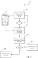
- Fig. 3 illustrates a flow-chart representation of a method for controlling a driving assistance feature of a vehicle in accordance with another exemplary embodiment of the present invention.
- the stored reaction model comprises a time threshold for each reaction parameter, i.e. a minimum time limit before which the driver is expected to react to the generated feedback signal (e.g. audio signal).
- the method 300 comprises measuring 301 one or more reaction parameters after the feedback signal has been outputted and comparing 302 the measurement result with a corresponding time threshold. More specifically, the method 300 comprises repeating the measurement 301 of the one or more reaction parameters N times (N being a predefined positive integer). Next, the method 300 comprises determining 303 how many measurements, denoted by X, that were below the associated time threshold.
- the method 300 comprises generating 304 a signal indicating that the feedback signal is perceived by the driver (i.e. the selected HMI output appears to be operational) if the number of measurements that indicated a reaction time below the associated threshold are above a predefined number M, M being a predefined positive integer > N.
- M may be based on a certain percentage (e.g. 90%); meaning that if nine out of ten measurements indicate that the feedback signal is perceived by the driver, then it is concluded that the HMI is working properly.
- the type of data that is stored can be both in the form of raw measurement data, as well as comparison data (only indicating if each measurement is above or below a certain threshold).
- Fig. 4 is a schematic illustration of a vehicle 1 comprising a vehicle control device 10 in accordance with an exemplary embodiment of the present invention.
- the control device comprises one or more processors 11, one or more memories 12, one or more sensor interfaces 13, and one or more communication interfaces 14.
- the processor(s) 11 may also be referred to as a control circuit 11.
- the control circuit 11 is configured to execute instructions stored in the memory 12 to perform a method for controlling a driving assistance feature of a vehicle according to any one of the embodiments disclosed herein.
- control circuit 11 is configured to determine a state of a driver of the vehicle 1 by means of a driver monitoring system (DMS) 22 the state of the driver comprising at least one attention parameter, and to compare the determined state of the driver with a predefined attention model.
- the predefined attention model comprises an independent threshold range for each attention parameter.
- control circuit 11 is configured to control the driving assistance feature based on the comparison between the determined state of the driver with a predefined attention model.
- the control circuit 11 can be configured to indirectly control the driving assistance feature by sending a control signal to a control unit of the driving assistance feature.
- the driver monitoring system 22 may for example comprise one or more cameras 23 configured to monitor and track the eyes of the driver in order to determine for example a blink frequency, a blink duration, a gaze direction duration, a head direction duration, an average gaze direction for a predefined time period, and/or an eye opening size.
- the control circuit 11 is further configured to send a feedback signal (via an HMI 24) to the driver based on the determined state of the driver. For example, if the DMS 22 signal indicates that the driver inattentive, a feedback signal (e.g. loud beep) may be output from a loudspeaker within the vehicle in order to notify the driver. Furthermore, the control circuit 11 is configured to receive a signal comprising information about (a measurement of) at least one reaction parameter of the driver from the DMS 22 after the feedback signal has been sent. Naturally, the signal need to necessarily be directly sent from the DMS, but may be indirectly received from the DMS via an intermediate control system of the vehicle 1. Then, the control circuit 11 is configured to compare the received information about the at least one reaction parameter with a stored reaction model.
- the stored reaction model comprises one or more reaction parameter thresholds, and/or reaction parameter threshold ranges.
- the vehicle 1 may be connected to external network(s) 20 via for instance a wireless link (e.g. for retrieving map data).
- a wireless link e.g. for retrieving map data
- the same or some other wireless link may be used to communicate with other vehicles in the vicinity of the vehicle or with local infrastructure elements.
- Cellular communication technologies may be used for long range communication such as to external networks and if the cellular communication technology used have low latency it may also be used for communication between vehicles, vehicle to vehicle (V2V), and/or vehicle to infrastructure, V2X.
- Examples of cellular radio technologies are GSM, GPRS, EDGE, LTE, 5G, 5G NR, and so on, also including future cellular solutions.
- LAN Wireless Local Area
- ETSI is working on cellular standards for vehicle communication and for instance 5G is considered as a suitable solution due to the low latency and efficient handling of high bandwidths and communication channels.
- a non-transitory computer-readable storage medium storing one or more programs configured to be executed by one or more processors of a vehicle control system, the one or more programs comprising instructions for performing the method according to any one of the above-discussed embodiments.
- a cloud computing system can be configured to perform any of the methods presented herein.
- the cloud computing system may comprise distributed cloud computing resources that jointly perform the methods presented herein under control of one or more computer program products.
- the processor(s) 11 may be or include any number of hardware components for conducting data or signal processing or for executing computer code stored in memory 12.
- the device 10 has an associated memory 12, and the memory 12 may be one or more devices for storing data and/or computer code for completing or facilitating the various methods described in the present description.
- the memory may include volatile memory or non-volatile memory.
- the memory 12 may include database components, object code components, script components, or any other type of information structure for supporting the various activities of the present description. According to an exemplary embodiment, any distributed or local memory device may be utilized with the systems and methods of this description.
- the memory 12 is communicably connected to the processor 11 (e.g., via a circuit or any other wired, wireless, or network connection) and includes computer code for executing one or more processes described herein.
- the sensor interface 13 may also provide the possibility to acquire sensor data directly or via dedicated sensor control circuitry in the vehicle.
- the communication/antenna interface 14 may further provide the possibility to send output to a remote location (e.g. remote operator or control centre) by means of the antenna 21.
- some sensors in the vehicle may communicate with the control device 10 using a local network setup, such as CAN bus, I2C, Ethernet, optical fibres, and so on.
- the communication interface 13 may be arranged to communicate with other control functions of the vehicle and may thus be seen as control interface also; however, a separate control interface (not shown) may be provided.
- Local communication within the vehicle may also be of a wireless type with protocols such as WiFi, LoRa, Zigbee, Bluetooth, or similar mid/short range technologies.
- parts of the described solution may be implemented either in the vehicle, in a system located external the vehicle, or in a combination of internal and external the vehicle; for instance in a server in communication with the vehicle, a so called cloud solution.
- the different features and steps of the embodiments may be combined in other combinations than those described.
Landscapes
- Engineering & Computer Science (AREA)
- Automation & Control Theory (AREA)
- Transportation (AREA)
- Mechanical Engineering (AREA)
- Human Computer Interaction (AREA)
- Physics & Mathematics (AREA)
- Mathematical Physics (AREA)
- Chemical & Material Sciences (AREA)
- Combustion & Propulsion (AREA)
- Traffic Control Systems (AREA)
Claims (15)
- Procédé (100) de commande d'une fonction d'assistance à la conduite d'un véhicule, le procédé comprenant les étapes consistant à :recevoir (100) un état d'un conducteur du véhicule déterminé au moyen d'un système de surveillance de conducteur, DMS, l'état du conducteur comprenant au moins un paramètre d'attention ;comparer (102) l'état déterminé du conducteur à un modèle d'attention prédéfini afin de vérifier une intégrité du DMS, le modèle d'attention prédéfini comprenant une plage de seuil indépendante pour chaque paramètre d'attention ;déterminer une fiabilité du DMS sur la base de la comparaison entre l'état déterminé du conducteur et le modèle d'attention prédéfini (102) ; etcommander (103) la fonction d'assistance à la conduite sur la base de la fiabilité déterminée du DMS.
- Procédé (100) selon la revendication 1, dans lequel l'étape de comparaison (102) de l'état déterminé du conducteur avec un modèle d'attention prédéfini comprend la comparaison de chaque paramètre d'attention avec chaque plage de seuil indépendante correspondante ; et
dans lequel l'étape de commande (103) de la fonction d'assistance à la conduite comprend la désactivation de la fonction d'assistance à la conduite si l'un quelconque des paramètres d'attention est en dehors de la plage de seuil indépendante correspondante. - Procédé (100) selon la revendication 1 ou 2, dans lequel l'au moins un paramètre d'attention comprend au moins l'une d'une fréquence de clignement, d'une durée de clignement, d'une durée de direction, d'une direction moyenne du regard pendant une période de temps prédéfinie et d'une taille d'ouverture des yeux.
- Procédé (100) selon l'une quelconque des revendications précédentes, comprenant en outre les étapes consistant à :envoyer (104) un signal de rétroaction au conducteur sur la base de l'état déterminé du conducteur ;mesurer (105) au moins un paramètre de réaction du conducteur au moyen du système de surveillance de conducteur après que le signal de retour a été envoyé ; etcomparer l'au moins un paramètre de réaction mesuré avec un modèle de réaction stocké.
- Procédé (100) selon la revendication 4, dans lequel le modèle de réaction stocké comprend au moins une plage de paramètres de réaction, le procédé comprenant en outre les étapes consistant à :répéter (201) la mesure de l'au moins un paramètre de réaction du conducteur une pluralité de fois ;stocker (201) la pluralité de mesures ;comparer (202) la pluralité stockée de mesures avec le modèle de réaction stocké ; etmettre à jour (203) l'au moins une plage de paramètres de réaction sur la base de la comparaison de la pluralité stockée de mesures avec le modèle de réaction stocké.
- Procédé (100) selon la revendication 5, dans lequel le modèle de réaction stocké comprend une pluralité de plages de paramètres de réaction, chaque plage de paramètres de réaction étant associée à un paramètre de réaction individuel, le procédé comprenant en outre :
la mise à jour (203) de la pluralité de plages de paramètres sur la base de la comparaison de la pluralité stockée de mesures avec le modèle de réaction stocké. - Procédé (100) selon l'une quelconque des revendications 4 à 6, dans lequel le modèle de réaction stocké comprend des seuils de temps pour chaque paramètre de réaction, le procédé comprenant en outre les étapes consistant à :comparer (302) l'au moins un paramètre de réaction mesuré à un seuil de temps correspondant ;répéter (301) la mesure et la comparaison N fois, N étant un entier positif prédéfini ;générer un signal indiquant que le signal de rétroaction est perçu (304) par le conducteur si M parmi N mesures sont inférieures au seuil temporel associé, M étant un entier positif prédéfini < N ; etgénérer un signal indiquant que le signal de rétroaction n'est pas perçu (305) par le conducteur si moins de M parmi N mesures sont inférieures au seuil temporel associé.
- Procédé (100) selon l'une quelconque des revendications 4 à 7, dans lequel le paramètre de réaction est choisi dans le groupe comprenant une direction du regard, un changement de direction du regard et une vitesse de changement de direction du regard.
- Support de stockage non transitoire et lisible par ordinateur, stockant un ou plusieurs programmes configurés pour être exécutés par un ou plusieurs processeurs d'un système de commande pour un véhicule, le ou les programmes comprenant des instructions pour exécuter le procédé selon l'une quelconque des revendications précédentes.
- Dispositif de commande de véhicule (10) pour commander une fonction d'assistance à la conduite d'un véhicule (1), le dispositif de commande de véhicule comprenant un circuit de commande (11) configuré pour :recevoir un état d'un conducteur du véhicule déterminé au moyen d'un système de surveillance de conducteur, DMS, (22) l'état du conducteur comprenant au moins un paramètre d'attention ;comparer l'état déterminé du conducteur à un modèle d'attention prédéfini afin de vérifier une intégrité du DMS, le modèle d'attention prédéfini comprenant une plage de seuil indépendante pour chaque paramètre d'attention ;déterminer une fiabilité du DMS sur la base de la comparaison entre l'état déterminé du conducteur et le modèle d'attention prédéfini ; etcommander la fonction d'assistance à la conduite sur la base de la fiabilité déterminée du DMS.
- Dispositif de commande de véhicule (10) selon la revendication 10, dans lequel le circuit de commande (11) est configuré pour comparer chaque paramètre d'attention avec chaque plage de seuil indépendante correspondante ; et
la commande de la fonction d'assistance à la conduite comprend la désactivation de la fonction d'assistance à la conduite si l'un quelconque des paramètres d'attention est en dehors de la plage de seuil indépendante correspondante. - Dispositif de commande de véhicule (10) selon la revendication 10 ou 11, dans lequel l'au moins un paramètre d'attention comprend au moins l'une d'une fréquence de clignement, d'une durée de clignement, d'une durée de direction, d'une direction moyenne du regard pendant une période de temps prédéfinie et d'une taille d'ouverture des yeux.
- Dispositif de commande de véhicule (10) selon l'une quelconque des revendications 10 à 12, dans lequel le circuit de commande (11) est en outre configuré pour :envoyer un signal de rétroaction au conducteur sur la base de l'état déterminé du conducteur ;recevoir un signal comprenant des informations sur au moins un paramètre de réaction du conducteur depuis le système de surveillance de conducteur (22) après que le signal de retour a été envoyé ; etcomparer les informations sur l'au moins un paramètre de réaction avec un modèle de réaction stocké.
- Dispositif de commande (10) selon la revendication 13, dans lequel le paramètre de réaction est choisi dans le groupe comprenant une direction du regard, un changement de direction du regard et une vitesse de changement de direction du regard.
- Véhicule (1) comprenant :un système de surveillance de conducteur, DMS, (22) pour mesurer la position des yeux et de la tête, l'attention et la fatigue du conducteur ; etun dispositif de commande de véhicule (10) selon l'une quelconque des revendications 11 à 14.
Priority Applications (4)
| Application Number | Priority Date | Filing Date | Title |
|---|---|---|---|
| EP19171430.2A EP3730331B1 (fr) | 2019-04-26 | 2019-04-26 | Procédé et dispositif pour contrôler une assistance à la conduite |
| US16/857,553 US11685383B2 (en) | 2019-04-26 | 2020-04-24 | Safety mechanism for assuring driver engagement during autonomous drive |
| CN202010340371.XA CN111845763B (zh) | 2019-04-26 | 2020-04-26 | 用于在自主驾驶期间确保驾驶员参与度的安全机构 |
| US18/317,168 US20230286513A1 (en) | 2019-04-26 | 2023-05-15 | Safety mechanism for assuring driver engagement during autonomous drive |
Applications Claiming Priority (1)
| Application Number | Priority Date | Filing Date | Title |
|---|---|---|---|
| EP19171430.2A EP3730331B1 (fr) | 2019-04-26 | 2019-04-26 | Procédé et dispositif pour contrôler une assistance à la conduite |
Publications (2)
| Publication Number | Publication Date |
|---|---|
| EP3730331A1 EP3730331A1 (fr) | 2020-10-28 |
| EP3730331B1 true EP3730331B1 (fr) | 2023-03-08 |
Family
ID=66483787
Family Applications (1)
| Application Number | Title | Priority Date | Filing Date |
|---|---|---|---|
| EP19171430.2A Active EP3730331B1 (fr) | 2019-04-26 | 2019-04-26 | Procédé et dispositif pour contrôler une assistance à la conduite |
Country Status (3)
| Country | Link |
|---|---|
| US (2) | US11685383B2 (fr) |
| EP (1) | EP3730331B1 (fr) |
| CN (1) | CN111845763B (fr) |
Families Citing this family (15)
| Publication number | Priority date | Publication date | Assignee | Title |
|---|---|---|---|---|
| KR102807503B1 (ko) * | 2019-05-14 | 2025-05-16 | 현대자동차주식회사 | 차량 및 그 제어방법 |
| WO2020241944A1 (fr) * | 2019-05-31 | 2020-12-03 | 엘지전자 주식회사 | Procédé de commande de véhicule et dispositif informatique intelligent pour commander un véhicule |
| US11447139B2 (en) * | 2019-12-20 | 2022-09-20 | Panasonic Intellectual Property Management Co., Ltd. | Driving assistance apparatus |
| US11912307B2 (en) * | 2020-03-18 | 2024-02-27 | Waymo Llc | Monitoring head movements of drivers tasked with monitoring a vehicle operating in an autonomous driving mode |
| DE102021104917A1 (de) * | 2021-03-02 | 2022-09-08 | Bayerische Motoren Werke Aktiengesellschaft | Fahrerüberwachungssystem für kraftfahrzeug |
| JP2022144818A (ja) * | 2021-03-19 | 2022-10-03 | 本田技研工業株式会社 | 運転支援装置、運転支援方法 |
| CN113044038B (zh) * | 2021-04-02 | 2022-08-05 | 中国第一汽车股份有限公司 | 一种车辆控制切换方法、装置、车辆及存储介质 |
| US11749032B2 (en) * | 2021-05-17 | 2023-09-05 | Toyota Research Institute, Inc. | Systems and methods for adapting notifications according to component monitoring |
| KR20230040660A (ko) * | 2021-09-16 | 2023-03-23 | 현대자동차주식회사 | 차량 및 그를 위한 운전자 보조 기능 제어 방법 |
| US11912313B2 (en) * | 2021-10-04 | 2024-02-27 | Arriver Software Llc | Human machine interaction monitor |
| US12157483B2 (en) * | 2022-05-05 | 2024-12-03 | Toyota Research Institute, Inc. | Systems and methods for driver state conditioned visual signals |
| CN114802369B (zh) * | 2022-05-06 | 2023-06-16 | 郑州铁路职业技术学院 | 一种列车辅助驾驶方法、系统、电子设备和存储介质 |
| FR3141404A1 (fr) * | 2022-10-31 | 2024-05-03 | Alstom Holdings | Dispositif de veille pour conducteur de véhicule ferroviaire, à confort amélioré |
| DE102022213126A1 (de) | 2022-12-06 | 2024-06-06 | Continental Automotive Technologies GmbH | Verfahren, Computerprogramm und Vorrichtung zur Beeinflussung eines Zustands eines Nutzers einer Maschine |
| DE102024129372A1 (de) | 2024-10-11 | 2026-04-16 | Bayerische Motoren Werke Aktiengesellschaft | Vorrichtung und Verfahren zum Überwachen der Aufmerksamkeit eines Fahrzeugführers |
Family Cites Families (29)
| Publication number | Priority date | Publication date | Assignee | Title |
|---|---|---|---|---|
| US6575902B1 (en) * | 1999-01-27 | 2003-06-10 | Compumedics Limited | Vigilance monitoring system |
| EP2314207A1 (fr) * | 2002-02-19 | 2011-04-27 | Volvo Technology Corporation | Procédé permettant de surveiller et de gérer les exigences posées à un pilote en termes d'attention |
| CN1918475B (zh) * | 2003-12-26 | 2011-08-17 | 博世株式会社 | 车身加速度传感器的故障诊断设备和防抱死制动系统 |
| JP4732848B2 (ja) * | 2004-11-02 | 2011-07-27 | 株式会社ブリヂストン | 異常判定装置及び異常判定方法 |
| DE102005057251A1 (de) * | 2005-11-29 | 2007-06-06 | Daimlerchrysler Ag | Verfahren zum automatischen Aus- und Wiedereinschalten einer Fahrassistenzvorrichtung |
| JP4720770B2 (ja) * | 2007-04-02 | 2011-07-13 | トヨタ自動車株式会社 | 車両用情報記録システム |
| DE102008038816A1 (de) | 2008-08-13 | 2010-02-18 | Volkswagen Ag | Verfahren und Vorrichtung zur Unterstützung des Betriebs eines Fahrzeugs |
| JP2011161956A (ja) * | 2010-02-04 | 2011-08-25 | Honda Motor Co Ltd | 中央制御装置 |
| JP5382048B2 (ja) * | 2011-04-05 | 2014-01-08 | 日本電気株式会社 | 差動信号故障検出装置及び差動信号故障検出方法 |
| JP5288045B2 (ja) * | 2011-07-11 | 2013-09-11 | トヨタ自動車株式会社 | 車両の緊急退避装置 |
| US8823530B2 (en) * | 2011-11-17 | 2014-09-02 | GM Global Technology Operations LLC | System and method for auto-correcting an autonomous driving system |
| US9751534B2 (en) * | 2013-03-15 | 2017-09-05 | Honda Motor Co., Ltd. | System and method for responding to driver state |
| GB2529997B (en) * | 2014-05-01 | 2019-01-02 | Jaguar Land Rover Ltd | Vehicle communication system with occupant monitoring |
| US9676393B2 (en) * | 2014-12-29 | 2017-06-13 | Automotive Research & Test Center | System and method for detecting environment-induced disablement of advanced driver assistance system |
| FR3037026B1 (fr) | 2015-06-04 | 2017-07-07 | Peugeot Citroen Automobiles Sa | Procede pour l’activation d’un mode autonome en reponse a une detection d’inattention |
| DE102015211126A1 (de) * | 2015-06-17 | 2016-12-22 | Bayerische Motoren Werke Aktiengesellschaft | Fahreraufmerksamkeitsüberwachung für automatische Fahrfunktionen |
| JP2017124670A (ja) * | 2016-01-12 | 2017-07-20 | トヨタ自動車株式会社 | 車両制御装置 |
| FR3048544B1 (fr) * | 2016-03-01 | 2021-04-02 | Valeo Comfort & Driving Assistance | Dispositif et methode de surveillance d'un conducteur d'un vehicule automobile |
| FR3048543A1 (fr) | 2016-03-01 | 2017-09-08 | Valeo Comfort & Driving Assistance | Dispositif et methode de surveillance d'un conducteur d'un vehicule de transport |
| US11001271B2 (en) * | 2016-07-12 | 2021-05-11 | Honda Motor Co., Ltd. | Drive assistance device |
| JP2018062308A (ja) * | 2016-10-14 | 2018-04-19 | オムロン株式会社 | 運転モード切替制御装置、方法およびプログラム |
| DE112016007335T5 (de) * | 2016-11-14 | 2019-06-27 | Ford Motor Company | Autonome fahrzeugsteuerung durch komparative übergangsprognose |
| JP6722097B2 (ja) * | 2016-12-09 | 2020-07-15 | エヌ・ティ・ティ・コムウェア株式会社 | 看視システム、看視方法、及びプログラム |
| JP6652090B2 (ja) * | 2017-03-10 | 2020-02-19 | オムロン株式会社 | 運転モード切替制御装置、システム、方法、およびプログラム |
| KR102539538B1 (ko) | 2017-10-24 | 2023-06-01 | 엘지디스플레이 주식회사 | 부피표현방식 3차원 표시장치 |
| JP7247499B2 (ja) * | 2018-09-20 | 2023-03-29 | いすゞ自動車株式会社 | 車両用監視装置 |
| US10807605B2 (en) * | 2018-12-19 | 2020-10-20 | Waymo Llc | Systems and methods for detecting and dynamically mitigating driver fatigue |
| US10967873B2 (en) * | 2019-01-30 | 2021-04-06 | Cobalt Industries Inc. | Systems and methods for verifying and monitoring driver physical attention |
| JP7307558B2 (ja) * | 2019-03-06 | 2023-07-12 | 株式会社Subaru | 車両の運転制御システム |
-
2019
- 2019-04-26 EP EP19171430.2A patent/EP3730331B1/fr active Active
-
2020
- 2020-04-24 US US16/857,553 patent/US11685383B2/en active Active
- 2020-04-26 CN CN202010340371.XA patent/CN111845763B/zh active Active
-
2023
- 2023-05-15 US US18/317,168 patent/US20230286513A1/en active Pending
Also Published As
| Publication number | Publication date |
|---|---|
| EP3730331A1 (fr) | 2020-10-28 |
| US11685383B2 (en) | 2023-06-27 |
| CN111845763B (zh) | 2024-05-31 |
| CN111845763A (zh) | 2020-10-30 |
| US20200339131A1 (en) | 2020-10-29 |
| US20230286513A1 (en) | 2023-09-14 |
Similar Documents
| Publication | Publication Date | Title |
|---|---|---|
| EP3730331B1 (fr) | Procédé et dispositif pour contrôler une assistance à la conduite | |
| US20200339133A1 (en) | Driver distraction determination | |
| CN113044043B (zh) | 自主车辆控制系统和使用该系统的自主车辆控制方法 | |
| CN111048171B (zh) | 解决晕动病的方法和装置 | |
| US9493116B2 (en) | Alert systems and methods for a vehicle | |
| CN107852357B (zh) | 安全装置、网络系统以及攻击检测方法 | |
| US9132774B2 (en) | Alert systems and methods for a vehicle | |
| US9701245B2 (en) | Alert systems and methods for a vehicle | |
| US8970358B2 (en) | Alert systems and methods for a vehicle | |
| US20190337451A1 (en) | Remote vehicle spatial awareness notification system | |
| US20150246639A1 (en) | Haptic alert system for a vehicle | |
| EP2942012A1 (fr) | Système d'assistance au conducteur | |
| US20130342365A1 (en) | Alert systems and methods for a vehicle | |
| US10752172B2 (en) | System and method to control a vehicle interface for human perception optimization | |
| CN104656503A (zh) | 自主车辆中的可穿戴计算机 | |
| US20130342364A1 (en) | Alert systems and methods for a vehicle | |
| CN117445944A (zh) | 用于车辆的驾驶员辅助系统 | |
| US20240372942A1 (en) | Notification system, vehicle control device, and notification method | |
| US20240367667A1 (en) | Notification system, vehicle control device, and notification method | |
| US20180304902A1 (en) | Enhanced message delivery | |
| JP7533366B2 (ja) | 通知判断装置、通知判断方法および通知判断プログラム | |
| CN115489461A (zh) | 座舱域控制设备及通过其发现显示错误的方法 | |
| EP4711224A1 (fr) | Véhicule, appareil, support de données, programme informatique, réseau neuronal et procédés pour une interface homme-machine | |
| US12030505B2 (en) | Vehicle occupant mental wellbeing assessment and countermeasure deployment | |
| US12434726B2 (en) | Vehicle driving assistance system |
Legal Events
| Date | Code | Title | Description |
|---|---|---|---|
| PUAI | Public reference made under article 153(3) epc to a published international application that has entered the european phase |
Free format text: ORIGINAL CODE: 0009012 |
|
| STAA | Information on the status of an ep patent application or granted ep patent |
Free format text: STATUS: THE APPLICATION HAS BEEN PUBLISHED |
|
| AK | Designated contracting states |
Kind code of ref document: A1 Designated state(s): AL AT BE BG CH CY CZ DE DK EE ES FI FR GB GR HR HU IE IS IT LI LT LU LV MC MK MT NL NO PL PT RO RS SE SI SK SM TR |
|
| AX | Request for extension of the european patent |
Extension state: BA ME |
|
| STAA | Information on the status of an ep patent application or granted ep patent |
Free format text: STATUS: REQUEST FOR EXAMINATION WAS MADE |
|
| 17P | Request for examination filed |
Effective date: 20210413 |
|
| RBV | Designated contracting states (corrected) |
Designated state(s): AL AT BE BG CH CY CZ DE DK EE ES FI FR GB GR HR HU IE IS IT LI LT LU LV MC MK MT NL NO PL PT RO RS SE SI SK SM TR |
|
| RIC1 | Information provided on ipc code assigned before grant |
Ipc: B60W 50/02 20120101ALN20220728BHEP Ipc: B60W 40/08 20120101ALN20220728BHEP Ipc: B60W 50/14 20200101ALI20220728BHEP Ipc: B60K 28/06 20060101AFI20220728BHEP |
|
| GRAP | Despatch of communication of intention to grant a patent |
Free format text: ORIGINAL CODE: EPIDOSNIGR1 |
|
| STAA | Information on the status of an ep patent application or granted ep patent |
Free format text: STATUS: GRANT OF PATENT IS INTENDED |
|
| RIC1 | Information provided on ipc code assigned before grant |
Ipc: B60W 50/02 20120101ALN20220907BHEP Ipc: B60W 40/08 20120101ALN20220907BHEP Ipc: B60W 50/14 20200101ALI20220907BHEP Ipc: B60K 28/06 20060101AFI20220907BHEP |
|
| INTG | Intention to grant announced |
Effective date: 20221007 |
|
| GRAS | Grant fee paid |
Free format text: ORIGINAL CODE: EPIDOSNIGR3 |
|
| GRAA | (expected) grant |
Free format text: ORIGINAL CODE: 0009210 |
|
| STAA | Information on the status of an ep patent application or granted ep patent |
Free format text: STATUS: THE PATENT HAS BEEN GRANTED |
|
| AK | Designated contracting states |
Kind code of ref document: B1 Designated state(s): AL AT BE BG CH CY CZ DE DK EE ES FI FR GB GR HR HU IE IS IT LI LT LU LV MC MK MT NL NO PL PT RO RS SE SI SK SM TR |
|
| REG | Reference to a national code |
Ref country code: CH Ref legal event code: EP Ref country code: AT Ref legal event code: REF Ref document number: 1552362 Country of ref document: AT Kind code of ref document: T Effective date: 20230315 |
|
| REG | Reference to a national code |
Ref country code: DE Ref legal event code: R096 Ref document number: 602019026051 Country of ref document: DE |
|
| REG | Reference to a national code |
Ref country code: IE Ref legal event code: FG4D |
|
| REG | Reference to a national code |
Ref country code: LT Ref legal event code: MG9D |
|
| P01 | Opt-out of the competence of the unified patent court (upc) registered |
Effective date: 20230525 |
|
| REG | Reference to a national code |
Ref country code: NL Ref legal event code: MP Effective date: 20230308 |
|
| PG25 | Lapsed in a contracting state [announced via postgrant information from national office to epo] |
Ref country code: RS Free format text: LAPSE BECAUSE OF FAILURE TO SUBMIT A TRANSLATION OF THE DESCRIPTION OR TO PAY THE FEE WITHIN THE PRESCRIBED TIME-LIMIT Effective date: 20230308 Ref country code: NO Free format text: LAPSE BECAUSE OF FAILURE TO SUBMIT A TRANSLATION OF THE DESCRIPTION OR TO PAY THE FEE WITHIN THE PRESCRIBED TIME-LIMIT Effective date: 20230608 Ref country code: LV Free format text: LAPSE BECAUSE OF FAILURE TO SUBMIT A TRANSLATION OF THE DESCRIPTION OR TO PAY THE FEE WITHIN THE PRESCRIBED TIME-LIMIT Effective date: 20230308 Ref country code: LT Free format text: LAPSE BECAUSE OF FAILURE TO SUBMIT A TRANSLATION OF THE DESCRIPTION OR TO PAY THE FEE WITHIN THE PRESCRIBED TIME-LIMIT Effective date: 20230308 Ref country code: HR Free format text: LAPSE BECAUSE OF FAILURE TO SUBMIT A TRANSLATION OF THE DESCRIPTION OR TO PAY THE FEE WITHIN THE PRESCRIBED TIME-LIMIT Effective date: 20230308 Ref country code: ES Free format text: LAPSE BECAUSE OF FAILURE TO SUBMIT A TRANSLATION OF THE DESCRIPTION OR TO PAY THE FEE WITHIN THE PRESCRIBED TIME-LIMIT Effective date: 20230308 |
|
| REG | Reference to a national code |
Ref country code: AT Ref legal event code: MK05 Ref document number: 1552362 Country of ref document: AT Kind code of ref document: T Effective date: 20230308 |
|
| PG25 | Lapsed in a contracting state [announced via postgrant information from national office to epo] |
Ref country code: SE Free format text: LAPSE BECAUSE OF FAILURE TO SUBMIT A TRANSLATION OF THE DESCRIPTION OR TO PAY THE FEE WITHIN THE PRESCRIBED TIME-LIMIT Effective date: 20230308 Ref country code: NL Free format text: LAPSE BECAUSE OF FAILURE TO SUBMIT A TRANSLATION OF THE DESCRIPTION OR TO PAY THE FEE WITHIN THE PRESCRIBED TIME-LIMIT Effective date: 20230308 Ref country code: GR Free format text: LAPSE BECAUSE OF FAILURE TO SUBMIT A TRANSLATION OF THE DESCRIPTION OR TO PAY THE FEE WITHIN THE PRESCRIBED TIME-LIMIT Effective date: 20230609 Ref country code: FI Free format text: LAPSE BECAUSE OF FAILURE TO SUBMIT A TRANSLATION OF THE DESCRIPTION OR TO PAY THE FEE WITHIN THE PRESCRIBED TIME-LIMIT Effective date: 20230308 |
|
| PG25 | Lapsed in a contracting state [announced via postgrant information from national office to epo] |
Ref country code: SM Free format text: LAPSE BECAUSE OF FAILURE TO SUBMIT A TRANSLATION OF THE DESCRIPTION OR TO PAY THE FEE WITHIN THE PRESCRIBED TIME-LIMIT Effective date: 20230308 Ref country code: RO Free format text: LAPSE BECAUSE OF FAILURE TO SUBMIT A TRANSLATION OF THE DESCRIPTION OR TO PAY THE FEE WITHIN THE PRESCRIBED TIME-LIMIT Effective date: 20230308 Ref country code: PT Free format text: LAPSE BECAUSE OF FAILURE TO SUBMIT A TRANSLATION OF THE DESCRIPTION OR TO PAY THE FEE WITHIN THE PRESCRIBED TIME-LIMIT Effective date: 20230710 Ref country code: EE Free format text: LAPSE BECAUSE OF FAILURE TO SUBMIT A TRANSLATION OF THE DESCRIPTION OR TO PAY THE FEE WITHIN THE PRESCRIBED TIME-LIMIT Effective date: 20230308 Ref country code: CZ Free format text: LAPSE BECAUSE OF FAILURE TO SUBMIT A TRANSLATION OF THE DESCRIPTION OR TO PAY THE FEE WITHIN THE PRESCRIBED TIME-LIMIT Effective date: 20230308 Ref country code: AT Free format text: LAPSE BECAUSE OF FAILURE TO SUBMIT A TRANSLATION OF THE DESCRIPTION OR TO PAY THE FEE WITHIN THE PRESCRIBED TIME-LIMIT Effective date: 20230308 |
|
| PG25 | Lapsed in a contracting state [announced via postgrant information from national office to epo] |
Ref country code: SK Free format text: LAPSE BECAUSE OF FAILURE TO SUBMIT A TRANSLATION OF THE DESCRIPTION OR TO PAY THE FEE WITHIN THE PRESCRIBED TIME-LIMIT Effective date: 20230308 Ref country code: PL Free format text: LAPSE BECAUSE OF FAILURE TO SUBMIT A TRANSLATION OF THE DESCRIPTION OR TO PAY THE FEE WITHIN THE PRESCRIBED TIME-LIMIT Effective date: 20230308 Ref country code: IS Free format text: LAPSE BECAUSE OF FAILURE TO SUBMIT A TRANSLATION OF THE DESCRIPTION OR TO PAY THE FEE WITHIN THE PRESCRIBED TIME-LIMIT Effective date: 20230708 |
|
| REG | Reference to a national code |
Ref country code: CH Ref legal event code: PL |
|
| REG | Reference to a national code |
Ref country code: DE Ref legal event code: R097 Ref document number: 602019026051 Country of ref document: DE |
|
| PG25 | Lapsed in a contracting state [announced via postgrant information from national office to epo] |
Ref country code: LU Free format text: LAPSE BECAUSE OF NON-PAYMENT OF DUE FEES Effective date: 20230426 |
|
| REG | Reference to a national code |
Ref country code: BE Ref legal event code: MM Effective date: 20230430 |
|
| PLBE | No opposition filed within time limit |
Free format text: ORIGINAL CODE: 0009261 |
|
| STAA | Information on the status of an ep patent application or granted ep patent |
Free format text: STATUS: NO OPPOSITION FILED WITHIN TIME LIMIT |
|
| PG25 | Lapsed in a contracting state [announced via postgrant information from national office to epo] |
Ref country code: MC Free format text: LAPSE BECAUSE OF FAILURE TO SUBMIT A TRANSLATION OF THE DESCRIPTION OR TO PAY THE FEE WITHIN THE PRESCRIBED TIME-LIMIT Effective date: 20230308 |
|
| PG25 | Lapsed in a contracting state [announced via postgrant information from national office to epo] |
Ref country code: SI Free format text: LAPSE BECAUSE OF FAILURE TO SUBMIT A TRANSLATION OF THE DESCRIPTION OR TO PAY THE FEE WITHIN THE PRESCRIBED TIME-LIMIT Effective date: 20230308 Ref country code: MC Free format text: LAPSE BECAUSE OF FAILURE TO SUBMIT A TRANSLATION OF THE DESCRIPTION OR TO PAY THE FEE WITHIN THE PRESCRIBED TIME-LIMIT Effective date: 20230308 Ref country code: LI Free format text: LAPSE BECAUSE OF NON-PAYMENT OF DUE FEES Effective date: 20230430 Ref country code: DK Free format text: LAPSE BECAUSE OF FAILURE TO SUBMIT A TRANSLATION OF THE DESCRIPTION OR TO PAY THE FEE WITHIN THE PRESCRIBED TIME-LIMIT Effective date: 20230308 Ref country code: CH Free format text: LAPSE BECAUSE OF NON-PAYMENT OF DUE FEES Effective date: 20230430 |
|
| 26N | No opposition filed |
Effective date: 20231211 |
|
| REG | Reference to a national code |
Ref country code: IE Ref legal event code: MM4A |
|
| PG25 | Lapsed in a contracting state [announced via postgrant information from national office to epo] |
Ref country code: BE Free format text: LAPSE BECAUSE OF NON-PAYMENT OF DUE FEES Effective date: 20230430 |
|
| PG25 | Lapsed in a contracting state [announced via postgrant information from national office to epo] |
Ref country code: IE Free format text: LAPSE BECAUSE OF NON-PAYMENT OF DUE FEES Effective date: 20230426 |
|
| PG25 | Lapsed in a contracting state [announced via postgrant information from national office to epo] |
Ref country code: IE Free format text: LAPSE BECAUSE OF NON-PAYMENT OF DUE FEES Effective date: 20230426 |
|
| PG25 | Lapsed in a contracting state [announced via postgrant information from national office to epo] |
Ref country code: IT Free format text: LAPSE BECAUSE OF FAILURE TO SUBMIT A TRANSLATION OF THE DESCRIPTION OR TO PAY THE FEE WITHIN THE PRESCRIBED TIME-LIMIT Effective date: 20230308 |
|
| PG25 | Lapsed in a contracting state [announced via postgrant information from national office to epo] |
Ref country code: BG Free format text: LAPSE BECAUSE OF FAILURE TO SUBMIT A TRANSLATION OF THE DESCRIPTION OR TO PAY THE FEE WITHIN THE PRESCRIBED TIME-LIMIT Effective date: 20230308 |
|
| PG25 | Lapsed in a contracting state [announced via postgrant information from national office to epo] |
Ref country code: BG Free format text: LAPSE BECAUSE OF FAILURE TO SUBMIT A TRANSLATION OF THE DESCRIPTION OR TO PAY THE FEE WITHIN THE PRESCRIBED TIME-LIMIT Effective date: 20230308 |
|
| PGFP | Annual fee paid to national office [announced via postgrant information from national office to epo] |
Ref country code: DE Payment date: 20250319 Year of fee payment: 7 |
|
| PG25 | Lapsed in a contracting state [announced via postgrant information from national office to epo] |
Ref country code: CY Free format text: LAPSE BECAUSE OF FAILURE TO SUBMIT A TRANSLATION OF THE DESCRIPTION OR TO PAY THE FEE WITHIN THE PRESCRIBED TIME-LIMIT; INVALID AB INITIO Effective date: 20190426 |
|
| PG25 | Lapsed in a contracting state [announced via postgrant information from national office to epo] |
Ref country code: HU Free format text: LAPSE BECAUSE OF FAILURE TO SUBMIT A TRANSLATION OF THE DESCRIPTION OR TO PAY THE FEE WITHIN THE PRESCRIBED TIME-LIMIT; INVALID AB INITIO Effective date: 20190426 |
|
| PG25 | Lapsed in a contracting state [announced via postgrant information from national office to epo] |
Ref country code: TR Free format text: LAPSE BECAUSE OF FAILURE TO SUBMIT A TRANSLATION OF THE DESCRIPTION OR TO PAY THE FEE WITHIN THE PRESCRIBED TIME-LIMIT Effective date: 20230308 |
|
| PGFP | Annual fee paid to national office [announced via postgrant information from national office to epo] |
Ref country code: GB Payment date: 20260217 Year of fee payment: 8 |
|
| PGFP | Annual fee paid to national office [announced via postgrant information from national office to epo] |
Ref country code: FR Payment date: 20260217 Year of fee payment: 8 |