EP3730412A1 - Système de capture, véhicule aérospatial et corps de type plaque - Google Patents
Système de capture, véhicule aérospatial et corps de type plaque Download PDFInfo
- Publication number
- EP3730412A1 EP3730412A1 EP20167231.8A EP20167231A EP3730412A1 EP 3730412 A1 EP3730412 A1 EP 3730412A1 EP 20167231 A EP20167231 A EP 20167231A EP 3730412 A1 EP3730412 A1 EP 3730412A1
- Authority
- EP
- European Patent Office
- Prior art keywords
- magnetic force
- plate
- aerospace vehicle
- target object
- generating portion
- Prior art date
- Legal status (The legal status is an assumption and is not a legal conclusion. Google has not performed a legal analysis and makes no representation as to the accuracy of the status listed.)
- Granted
Links
Images



Classifications
-
- B—PERFORMING OPERATIONS; TRANSPORTING
- B64—AIRCRAFT; AVIATION; COSMONAUTICS
- B64G—COSMONAUTICS; VEHICLES OR EQUIPMENT THEREFOR
- B64G1/00—Cosmonautic vehicles
- B64G1/22—Parts of, or equipment specially adapted for fitting in or to, cosmonautic vehicles
- B64G1/66—Arrangements or adaptations of apparatus or instruments, not otherwise provided for
-
- B—PERFORMING OPERATIONS; TRANSPORTING
- B64—AIRCRAFT; AVIATION; COSMONAUTICS
- B64G—COSMONAUTICS; VEHICLES OR EQUIPMENT THEREFOR
- B64G1/00—Cosmonautic vehicles
- B64G1/22—Parts of, or equipment specially adapted for fitting in or to, cosmonautic vehicles
- B64G1/64—Systems for coupling or separating cosmonautic vehicles or parts thereof, e.g. docking arrangements
- B64G1/646—Docking or rendezvous systems
- B64G1/6462—Docking or rendezvous systems characterised by the means for engaging other vehicles
-
- G—PHYSICS
- G01—MEASURING; TESTING
- G01B—MEASURING LENGTH, THICKNESS OR SIMILAR LINEAR DIMENSIONS; MEASURING ANGLES; MEASURING AREAS; MEASURING IRREGULARITIES OF SURFACES OR CONTOURS
- G01B11/00—Measuring arrangements characterised by the use of optical techniques
- G01B11/26—Measuring arrangements characterised by the use of optical techniques for measuring angles or tapers; for testing the alignment of axes
-
- B—PERFORMING OPERATIONS; TRANSPORTING
- B64—AIRCRAFT; AVIATION; COSMONAUTICS
- B64G—COSMONAUTICS; VEHICLES OR EQUIPMENT THEREFOR
- B64G4/00—Tools specially adapted for use in space
- B64G2004/005—Robotic manipulator systems for use in space
Definitions
- the present subject disclosure relates to a capturing system, an aerospace vehicle, and a plate-like body.
- a technique which includes bringing a mother unit close to the debris, capturing the debris by a robot arm provided on the mother unit, attaching a conductive tether device to the debris, , and decelerating the debris by an electromagnetic force acting on the tether (Japanese Patent Laid-Open No. 2004-98959 ).
- a technique has been proposed which includes, in order to release and deploy a tether in space, bringing a mother unit close to debris, ejecting a harpoon with the tether from a debris capturing device provided on the mother unit towards the debris, and causing the harpoon to penetrate into the debris (Japanese Patent Laid-Open No. 2016-68730 ).
- the robot arm has a complicated mechanism, and therefore, the mass and the size of the device increase, so that the cost for development, manufacturing, or launch becomes very high.
- a harpoon ejecting mechanism is required, which increases the cost.
- the ejection of the harpoon has failed once, the ejection cannot be redone, and therefore, there has been a possibility that the success rate of the mission has decreased.
- the present subject disclosure has been made in view of such circumstances.
- the objective of the present subject disclosure is to increase the success rate of missions at a low cost for a capturing system which captures a target object in space.
- a capturing system captures a target object in space and has: a plate-like body which is attached to the target object and attracted with a magnetic force; and an aerospace vehicle that has a magnetic force generating portion which generates the magnetic force attracting the plate-like body.
- An aerospace vehicle according to the present subject disclosure has a magnetic force generating portion generating a magnetic force that enables capturing of a target object in space by attracting a plate-like body, which is attached to the target object and attracted with magnetic force, with magnetic force generated by the magnetic force generating portion.
- a plate-like body according to the present subject disclosure is attached to a target object in space before the target object is launched to space, and enables the aerospace vehicle to capture the target object by being attracted with magnetic force generated by the magnetic force generating portion of the aerospace vehicle.
- a target object in space can be captured by attaching a plate-like body, which is attracted with magnetic force, to the target object prior to launch, and then attracting the plate-like body with magnetic force generated by the magnetic force generating portion of the aerospace vehicle.
- the plate-like body which is attached to the target object prior to launch has no electrical or mechanical structures, and the mechanism of the magnetic force generating portion of the aerospace vehicle is relatively simple. Therefore, the development or manufacturing cost can be markedly reduced.
- the capturing system according to the present subject disclosure can employ a magnetic force generating portion that has a plate-like member and a magnetic portion placed on the surface of the plate-like member.
- a magnetic force generating portion that has a plate-like member and a magnetic portion placed on the surface of the plate-like member.
- two or more of the magnetic portions can be placed at a predetermined interval along the peripheral edge of the plate-like member.
- the magnetic portion a permanent magnet can be employed.
- the magnetic force generating portion can be configured at a relatively low cost.
- an electromagnet that generates a magnetic force by applying an electric current may be employed as the magnetic portion.
- the electric current applied to the electromagnet is stopped to temporarily eliminate the magnetic force, whereby the undesired attachment can be canceled. Thereafter, by restarting the current application to the electromagnet as necessary, the attraction between the magnetic force generating portion and the plate-like body can be resumed.
- the capturing system according to the present subject disclosure can employ an aerospace vehicle that has a body and a rod-shaped member that may be deployed and retracted from the body.
- the magnetic force generating portion can be attached to the tip of the rod-shaped member.
- the magnetic force generating portion is attached to the tip of the rod-shaped member that may be deployed and retracted from the body of the aerospace vehicle. Therefore, in capturing a target object, the rod-shaped member is deployed from the body of the aerospace vehicle to the plate-like body of the target object, so that the magnetic force generating portion can be brought close to the plate-like body. On the other hand, when the aerospace vehicle travels in space, the rod-shaped member can be retracted into the body. Therefore, the interference between portions other than the plate-like body of the target object, such as antennas, nozzles, or solar cells, and the rod-shaped member can be prevented.
- the action of the load of the entire aerospace vehicle on the target object can be prevented. Therefore, the influence on the target object can be minimized.
- the plate-like body can have a portion containing magnetic materials, such as iron, nickel, permalloy, steel, and others.
- the success rate of a mission thereof can be increased at a low cost.
- the capturing system 1 is one for capturing a target object (for example, debris) T in space, which has a plate-like body 10 attached to the target object T and an aerospace vehicle 20 having a magnetic force generating portion 23 (described later) generating magnetic a force that attracts the plate-like body 10, as illustrated in FIG. 1 .
- a target object for example, debris
- an aerospace vehicle 20 having a magnetic force generating portion 23 (described later) generating magnetic a force that attracts the plate-like body 10, as illustrated in FIG. 1 .
- the plate-like body 10 is a plate-like member having a circular shape as viewed in a plan view, has a predetermined thickness, and is attached beforehand to a predetermined portion (for example, a flat portion) of the target object T.
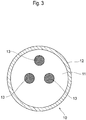
- the plate-like body 10 in this embodiment has a central portion 11 containing aluminum and a peripheral portion 12 containing iron as illustrated in FIG. 3 , and is configured so that the peripheral portion 12 containing iron, which is a magnetic material, is attracted to the magnetic force generating portion 23 of the aerospace vehicle 20.
- the peripheral portion 12 can also contain other magnetic materials (for example, nickel, permalloy, steel, etc.) in place of iron. Both the central portion 11 and the peripheral portion 12 may contain magnetic materials, such as iron.
- the area of the plate-like body 10 can be set to be either equal to or slightly larger than the area of the magnetic force generating portion 23 of the aerospace vehicle 20.
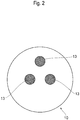
- markers 13 can be placed for approach navigation of the aerospace vehicle 20.
- the markers 13 show a certain geometric pattern, and three or more circles can be arranged in a predetermined pattern.
- the markers 13 contain materials (for example, glass beads, a corner cube mirror, etc.) capable of reflecting light emitted from the aerospace vehicle 20 directly towards the aerospace vehicle 20.
- materials for example, glass beads, a corner cube mirror, etc.
- at least three markers 13 are preferably placed.
- specific surface processing can be applied to the plate-like body 10.
- the aerospace vehicle 20 is configured so as to be attached to a rocket and launched into space, and then separated from the rocket to be autonomously movable in the space and has a body 21 having an approximately rectangular parallelepiped shape and a rod-shaped member 22 having an approximately cylindrical shape projectable and retractable from the body 21 as illustrated in FIG. 4 .
- the aerospace vehicle 20 is launched or moves in the space, the aerospace vehicle 20 is set to a state where the rod-shaped member 22 is retracted into the body 21 as illustrated in FIG. 5 .
- the magnetic force generating portion 23 generating magnetic force attracting the plate-like body 10 to the target object T is attached to the tip of the rod-shaped member 22 of the aerospace vehicle 20.
- the magnetic force generating portion 23 has a plate-like member 23a having a circular shape as viewed in a plan view and magnetic portions 23b provided on the surface of the plate-like member 23a as illustrated in FIG. 6 .
- a permanent magnet having a circular shape as viewed in a plan view is employed as the magnetic portion 23b and two or more of the permanent magnets are provided at a predetermined interval along the peripheral edge of the plate-like member 23a as illustrated in FIG. 6 .
- the magnetic force generated by the magnetic force generating portion 23 is set to a value (for example, 4 N) with which the plate-like body 10 can be attracted.
- the aerospace vehicle 20 can facilitate the navigation when approaching by recognizing the markers 13 or the like attached to the central portion of the plate-like body 10 with a camera 24 or the like of the aerospace vehicle 20 as illustrated in FIG. 6 .
- the area per magnetic portion 23b, the position and the number of the magnetic portions 23b, and the like can be altered as appropriate.
- a large number of magnetic portions 23b having a relatively small area can also be provided as illustrated in FIG. 7 .
- the aerospace vehicle 20 is moved towards the target object T.
- the aerospace vehicle 20 searches for the plate-like body 10 attached to the target object T while performing imaging with the camera 24.
- the search of the plate-like body 10 is completed through reflecting light emitted from a light projector on the surface of the markers 13 attached to the surface of the plate-like body 10, capturing the light with the camera 24, and then recognizing the same by an arithmetic operation portion, for example.
- the aerospace vehicle 20 is movable so as to approach the target object T.
- the rod-shaped member 22 of the aerospace vehicle 20 is projected from the body 21 to the plate-like body 10 of the target object T. Then, the plate-like body 10 attached to the target object T beforehand is attracted with magnetic force generated by the magnetic force generating portion 23 attached to the tip of the rod-shaped member 22 of the aerospace vehicle 20. Then, the rod-shaped member 22 of the aerospace vehicle 20 is retracted into the body 21 side, whereby the target object T is brought close to the aerospace vehicle 20 to be captured.
- the plate-like body 10 to be attracted with magnetic force is attached to the target object T in the space beforehand, and then the plate-like body 10 is attracted with magnetic force generated by the magnetic force generating portion 23 of the aerospace vehicle 20, whereby the target object T can be captured.
- the plate-like body 10 attached to the target object T beforehand has no electrical and mechanical structures and the mechanism of the magnetic force generating portion 23 of the aerospace vehicle 20 is also relatively simple, and therefore the development/manufacturing cost can be markedly reduced.
- the permanent magnet is employed as the magnetic portion 23b, and therefore the magnetic force generating portion 23 can be configured at a relatively low cost.
- the magnetic force generating portion 23 is attached to the tip of the rod-shaped member 22 projectably and retractably provided to the body 21 of the aerospace vehicle 20. Therefore, when capturing the target object T, the magnetic force generating portion 23 can be brought close to the plate-like body 10 by projecting the rod-shaped member 22 from the body 21 of the aerospace vehicle 20 to the plate-like body 10 of the target object T. On the other hand, when the aerospace vehicle 20 travels in the space, the rod-shaped member 22 can be retracted into the body 21.
- the interference between the other portions (portions other than the plate-like body 10, such as an antenna, a nozzle, and a solar cell) and the rod-shaped member 22 of the target object T can be prevented.
- the tip (magnetic force generating portion 23) of the rod-shaped member 22 provided to the aerospace vehicle 20 the action of the load of the entire aerospace vehicle 20 on the target object T can be prevented. Therefore, the influence on the target object T can be minimized.
- This embodiment describes the example in which a permanent magnet is employed as the magnetic portion 23b configuring the magnetic force generating portion 23 but an electromagnet generating magnetic force by current application can also be employed in place of the permanent magnet.
- a permanent magnet is employed as the magnetic portion 23b configuring the magnetic force generating portion 23 but an electromagnet generating magnetic force by current application can also be employed in place of the permanent magnet.
- the magnetic force of the permanent magnet can be eliminated by current application.
- continuous power is not required in the attraction state and, when the magnetic force generating portion 23 and the plate-like body 10 enter an inappropriate attraction state, the inappropriate attraction state can be cancelled by current application for a short period of time. Thereafter, by restarting the current application to the electromagnet as necessary, the attraction between the magnetic force generating portion 23 and the plate-like body 10 can be realized again.
- the plane shape of the plate-like body 10 to be attached to the target object T is set to a circular shape but the plane shape of the plate-like body 10 is not limited to the circular shape and may be a polygonal shape (triangular shape, square shape, hexagonal shape, and the like), for example.
- the plane shape of the plate-like member 23a of the magnetic force generating portion 23 of the aerospace vehicle 20 is also not limited to the circular shape and can be set to a polygonal shape, for example.
- the shape of the aerospace vehicle 20 is also not limited to the approximately rectangular parallelepiped shape and can be set to an approximately columnar shape, for example.
- the present subject disclosure is not limited to the embodiment described above and embodiments obtained by adding design changes to the embodiment described above as appropriate by a person skilled in the art are also included in the scope of the present subject disclosure insofar as the embodiments have the features of the present subject disclosure. More specifically, the elements of the embodiment described above and the arrangement, materials, conditions, shapes, sizes, and the like thereof are not necessarily limited to those described as examples and can be altered as appropriate. Moreover, the elements of the embodiment described above can be combined as long as the combination is technically allowed and those obtained by combining the elements are also included in the scope of the present subject disclosure insofar as the combinations include the features of the present subject disclosure.
Landscapes
- Engineering & Computer Science (AREA)
- Remote Sensing (AREA)
- Aviation & Aerospace Engineering (AREA)
- Physics & Mathematics (AREA)
- General Physics & Mathematics (AREA)
- Manipulator (AREA)
- Control Of Position, Course, Altitude, Or Attitude Of Moving Bodies (AREA)
- Road Signs Or Road Markings (AREA)
- Traffic Control Systems (AREA)
Applications Claiming Priority (2)
| Application Number | Priority Date | Filing Date | Title |
|---|---|---|---|
| JP2017025747 | 2017-02-15 | ||
| EP17165426.2A EP3363744B1 (fr) | 2017-02-15 | 2017-04-07 | Système de capture, véhicule aérospatial et corps de type plaque |
Related Parent Applications (2)
| Application Number | Title | Priority Date | Filing Date |
|---|---|---|---|
| EP17165426.2A Division EP3363744B1 (fr) | 2017-02-15 | 2017-04-07 | Système de capture, véhicule aérospatial et corps de type plaque |
| EP17165426.2A Division-Into EP3363744B1 (fr) | 2017-02-15 | 2017-04-07 | Système de capture, véhicule aérospatial et corps de type plaque |
Publications (2)
| Publication Number | Publication Date |
|---|---|
| EP3730412A1 true EP3730412A1 (fr) | 2020-10-28 |
| EP3730412B1 EP3730412B1 (fr) | 2022-08-10 |
Family
ID=58994817
Family Applications (2)
| Application Number | Title | Priority Date | Filing Date |
|---|---|---|---|
| EP17165426.2A Active EP3363744B1 (fr) | 2017-02-15 | 2017-04-07 | Système de capture, véhicule aérospatial et corps de type plaque |
| EP20167231.8A Active EP3730412B1 (fr) | 2017-02-15 | 2017-04-07 | Véhicule aerospatial pour capturer un objet dans l'espace |
Family Applications Before (1)
| Application Number | Title | Priority Date | Filing Date |
|---|---|---|---|
| EP17165426.2A Active EP3363744B1 (fr) | 2017-02-15 | 2017-04-07 | Système de capture, véhicule aérospatial et corps de type plaque |
Country Status (3)
| Country | Link |
|---|---|
| US (1) | US20180229865A1 (fr) |
| EP (2) | EP3363744B1 (fr) |
| JP (2) | JPWO2018150883A1 (fr) |
Families Citing this family (10)
| Publication number | Priority date | Publication date | Assignee | Title |
|---|---|---|---|---|
| JP6722514B2 (ja) * | 2016-05-27 | 2020-07-15 | 株式会社アストロスケール | 捕獲プレート、宇宙用装置及び捕獲方法 |
| CN109466808B (zh) * | 2018-12-14 | 2021-04-09 | 哈尔滨工业大学 | 一种基于直线电机的电磁对接装置及方法 |
| CN112173176B (zh) * | 2019-07-02 | 2022-02-18 | 中国科学院宁波材料技术与工程研究所 | 一种电永磁对接分离装置及其对接分离方法 |
| US11643227B2 (en) | 2019-09-24 | 2023-05-09 | Astroscale Israel, Ltd. | In-orbit spacecraft servicing through umbilical connectors |
| CN110979754B (zh) * | 2019-11-28 | 2023-01-31 | 兰州空间技术物理研究所 | 一种基于充气结构的空间碎片弹射与捕获装置及方法 |
| JP7429181B2 (ja) * | 2020-10-16 | 2024-02-07 | 株式会社アストロスケール | 宇宙航行体及び捕獲システム |
| WO2022153619A1 (fr) | 2021-01-15 | 2022-07-21 | Astroscale Holdings Inc. | Procédé et système d'élimination de débris spatiaux multi-objet |
| CN114104344B (zh) * | 2021-12-07 | 2024-06-21 | 哈尔滨工业大学 | 一种用于空间捕获非合作目标的柔性气动抓捕机构 |
| CN115610707B (zh) * | 2022-12-19 | 2023-04-04 | 哈尔滨工业大学 | 一种用于航天器的在轨对接方法和对接系统 |
| CN116678266B (zh) * | 2023-05-15 | 2025-10-28 | 大连理工大学 | 一种基于强磁阵列的导弹尾罩分离装置 |
Citations (4)
| Publication number | Priority date | Publication date | Assignee | Title |
|---|---|---|---|---|
| US5145227A (en) * | 1990-12-31 | 1992-09-08 | The United States Of America As Represented By The Administrator Of The National Aeronautics And Space Administration | Electromagnetic attachment mechanism |
| JP2004098959A (ja) | 2002-09-12 | 2004-04-02 | National Aerospace Laboratory Of Japan | スペースデブリ軌道変換用テザー装置 |
| US20110192936A1 (en) * | 2010-02-10 | 2011-08-11 | Astrium Gmbh | Towing Apparatus for a Spacecraft when in Orbit and a Towing Spacecraft |
| JP2016068730A (ja) | 2014-09-30 | 2016-05-09 | 株式会社Ihi | デブリ除去装置及びデブリ除去方法 |
Family Cites Families (10)
| Publication number | Priority date | Publication date | Assignee | Title |
|---|---|---|---|---|
| US4834531A (en) * | 1985-10-31 | 1989-05-30 | Energy Optics, Incorporated | Dead reckoning optoelectronic intelligent docking system |
| JPS62167800U (fr) * | 1986-04-15 | 1987-10-24 | ||
| JPH0523989A (ja) * | 1991-07-15 | 1993-02-02 | Hitachi Ltd | 宇宙ロボツト用のマグネツト式エンドエフエクタ |
| JP2500616B2 (ja) * | 1993-05-31 | 1996-05-29 | 日本電気株式会社 | 帯電電位等化方法 |
| JPH06340299A (ja) * | 1993-06-01 | 1994-12-13 | Mitsubishi Heavy Ind Ltd | 宇宙機用相対位置検出装置 |
| JP2000142598A (ja) * | 1998-11-13 | 2000-05-23 | Nec Eng Ltd | 電磁石を使用した宇宙飛行体の結合・分離装置、及び、結合・分離方法 |
| DE10342953B4 (de) * | 2003-09-17 | 2007-11-22 | Astrium Gmbh | Vorrichtung zum Greifen von Objekten im All |
| US7515257B1 (en) * | 2004-12-15 | 2009-04-07 | The United States Of America As Represented By The Administrator Of The National Aeronautics And Space Administration | Short-range/long-range integrated target (SLIT) for video guidance sensor rendezvous and docking |
| US7607616B2 (en) * | 2006-11-29 | 2009-10-27 | The Boeing Company | Docking device |
| JP3156750U (ja) * | 2009-10-30 | 2010-01-14 | ニチレイマグネット株式会社 | 壁面装着具の取り付け構造 |
-
2017
- 2017-04-07 EP EP17165426.2A patent/EP3363744B1/fr active Active
- 2017-04-07 EP EP20167231.8A patent/EP3730412B1/fr active Active
- 2017-04-07 US US15/482,586 patent/US20180229865A1/en not_active Abandoned
-
2018
- 2018-02-01 JP JP2018568095A patent/JPWO2018150883A1/ja active Pending
-
2020
- 2020-08-27 JP JP2020143521A patent/JP6913217B2/ja active Active
Patent Citations (4)
| Publication number | Priority date | Publication date | Assignee | Title |
|---|---|---|---|---|
| US5145227A (en) * | 1990-12-31 | 1992-09-08 | The United States Of America As Represented By The Administrator Of The National Aeronautics And Space Administration | Electromagnetic attachment mechanism |
| JP2004098959A (ja) | 2002-09-12 | 2004-04-02 | National Aerospace Laboratory Of Japan | スペースデブリ軌道変換用テザー装置 |
| US20110192936A1 (en) * | 2010-02-10 | 2011-08-11 | Astrium Gmbh | Towing Apparatus for a Spacecraft when in Orbit and a Towing Spacecraft |
| JP2016068730A (ja) | 2014-09-30 | 2016-05-09 | 株式会社Ihi | デブリ除去装置及びデブリ除去方法 |
Also Published As
| Publication number | Publication date |
|---|---|
| EP3363744A1 (fr) | 2018-08-22 |
| JPWO2018150883A1 (ja) | 2020-03-26 |
| JP6913217B2 (ja) | 2021-08-04 |
| JP2020189632A (ja) | 2020-11-26 |
| EP3363744B1 (fr) | 2022-07-27 |
| EP3730412B1 (fr) | 2022-08-10 |
| US20180229865A1 (en) | 2018-08-16 |
Similar Documents
| Publication | Publication Date | Title |
|---|---|---|
| EP3730412B1 (fr) | Véhicule aerospatial pour capturer un objet dans l'espace | |
| US12122540B2 (en) | Space vehicle and capture system | |
| EP3901044B1 (fr) | Système de capture, véhicule aérospatial et corps de type plaque | |
| US10407184B2 (en) | Debris removal device and debris removal method | |
| US8052092B2 (en) | Method and apparatus for satellite orbital change using space debris | |
| CN116374219B (zh) | 一种可重复解锁微纳卫星的对接机构和方法 | |
| US20190359357A1 (en) | Space-debris capturing device and space-debris removing device | |
| JP7713523B2 (ja) | マルチオブジェクトスペースデブリ除去のための方法及びシステム | |
| EP3112274A1 (fr) | Système spatial pour réduire les vitesses angulaires d'un débris spatial avant de le désorbiter | |
| JP6723950B2 (ja) | 捕獲システム、宇宙航行体及び板状体 | |
| CN109592080B (zh) | 一种系绳-电磁协同控制的微纳星柔性回收方法及装置 | |
| US11548657B2 (en) | Aerial vehicle securing system and method | |
| CN115027705B (zh) | 一种可重复的模块化空间柔性网快速自组装机构 | |
| Kojima et al. | Ellipse detection-based visual servo control for capturing upper-stage rocket body | |
| KR102195933B1 (ko) | 드론용 도킹장치 | |
| CN108945328A (zh) | 一种用于无人机的水上回收装置 | |
| RU2710844C1 (ru) | Космическое буксирное устройство | |
| UA125907C2 (uk) | Аеромагнітна система відведення об'єктів космічного сміття з низьких навколоземних орбіт з магнітними органами керування | |
| WO2020031266A1 (fr) | Système de modification d'orbite d'objet et procédé de modification d'orbite d'objet |
Legal Events
| Date | Code | Title | Description |
|---|---|---|---|
| PUAI | Public reference made under article 153(3) epc to a published international application that has entered the european phase |
Free format text: ORIGINAL CODE: 0009012 |
|
| STAA | Information on the status of an ep patent application or granted ep patent |
Free format text: STATUS: THE APPLICATION HAS BEEN PUBLISHED |
|
| AC | Divisional application: reference to earlier application |
Ref document number: 3363744 Country of ref document: EP Kind code of ref document: P |
|
| AK | Designated contracting states |
Kind code of ref document: A1 Designated state(s): AL AT BE BG CH CY CZ DE DK EE ES FI FR GB GR HR HU IE IS IT LI LT LU LV MC MK MT NL NO PL PT RO RS SE SI SK SM TR |
|
| STAA | Information on the status of an ep patent application or granted ep patent |
Free format text: STATUS: REQUEST FOR EXAMINATION WAS MADE |
|
| 17P | Request for examination filed |
Effective date: 20210423 |
|
| RBV | Designated contracting states (corrected) |
Designated state(s): AL AT BE BG CH CY CZ DE DK EE ES FI FR GB GR HR HU IE IS IT LI LT LU LV MC MK MT NL NO PL PT RO RS SE SI SK SM TR |
|
| GRAP | Despatch of communication of intention to grant a patent |
Free format text: ORIGINAL CODE: EPIDOSNIGR1 |
|
| STAA | Information on the status of an ep patent application or granted ep patent |
Free format text: STATUS: GRANT OF PATENT IS INTENDED |
|
| INTG | Intention to grant announced |
Effective date: 20220509 |
|
| GRAS | Grant fee paid |
Free format text: ORIGINAL CODE: EPIDOSNIGR3 |
|
| GRAA | (expected) grant |
Free format text: ORIGINAL CODE: 0009210 |
|
| STAA | Information on the status of an ep patent application or granted ep patent |
Free format text: STATUS: THE PATENT HAS BEEN GRANTED |
|
| AC | Divisional application: reference to earlier application |
Ref document number: 3363744 Country of ref document: EP Kind code of ref document: P |
|
| AK | Designated contracting states |
Kind code of ref document: B1 Designated state(s): AL AT BE BG CH CY CZ DE DK EE ES FI FR GB GR HR HU IE IS IT LI LT LU LV MC MK MT NL NO PL PT RO RS SE SI SK SM TR |
|
| REG | Reference to a national code |
Ref country code: AT Ref legal event code: REF Ref document number: 1510390 Country of ref document: AT Kind code of ref document: T Effective date: 20220815 Ref country code: CH Ref legal event code: EP |
|
| REG | Reference to a national code |
Ref country code: IE Ref legal event code: FG4D |
|
| REG | Reference to a national code |
Ref country code: DE Ref legal event code: R096 Ref document number: 602017060658 Country of ref document: DE |
|
| REG | Reference to a national code |
Ref country code: NL Ref legal event code: MP Effective date: 20220810 |
|
| REG | Reference to a national code |
Ref country code: LT Ref legal event code: MG9D |
|
| PG25 | Lapsed in a contracting state [announced via postgrant information from national office to epo] |
Ref country code: SE Free format text: LAPSE BECAUSE OF FAILURE TO SUBMIT A TRANSLATION OF THE DESCRIPTION OR TO PAY THE FEE WITHIN THE PRESCRIBED TIME-LIMIT Effective date: 20220810 Ref country code: RS Free format text: LAPSE BECAUSE OF FAILURE TO SUBMIT A TRANSLATION OF THE DESCRIPTION OR TO PAY THE FEE WITHIN THE PRESCRIBED TIME-LIMIT Effective date: 20220810 Ref country code: PT Free format text: LAPSE BECAUSE OF FAILURE TO SUBMIT A TRANSLATION OF THE DESCRIPTION OR TO PAY THE FEE WITHIN THE PRESCRIBED TIME-LIMIT Effective date: 20221212 Ref country code: NO Free format text: LAPSE BECAUSE OF FAILURE TO SUBMIT A TRANSLATION OF THE DESCRIPTION OR TO PAY THE FEE WITHIN THE PRESCRIBED TIME-LIMIT Effective date: 20221110 Ref country code: NL Free format text: LAPSE BECAUSE OF FAILURE TO SUBMIT A TRANSLATION OF THE DESCRIPTION OR TO PAY THE FEE WITHIN THE PRESCRIBED TIME-LIMIT Effective date: 20220810 Ref country code: LV Free format text: LAPSE BECAUSE OF FAILURE TO SUBMIT A TRANSLATION OF THE DESCRIPTION OR TO PAY THE FEE WITHIN THE PRESCRIBED TIME-LIMIT Effective date: 20220810 Ref country code: LT Free format text: LAPSE BECAUSE OF FAILURE TO SUBMIT A TRANSLATION OF THE DESCRIPTION OR TO PAY THE FEE WITHIN THE PRESCRIBED TIME-LIMIT Effective date: 20220810 Ref country code: FI Free format text: LAPSE BECAUSE OF FAILURE TO SUBMIT A TRANSLATION OF THE DESCRIPTION OR TO PAY THE FEE WITHIN THE PRESCRIBED TIME-LIMIT Effective date: 20220810 |
|
| REG | Reference to a national code |
Ref country code: AT Ref legal event code: MK05 Ref document number: 1510390 Country of ref document: AT Kind code of ref document: T Effective date: 20220810 |
|
| PG25 | Lapsed in a contracting state [announced via postgrant information from national office to epo] |
Ref country code: PL Free format text: LAPSE BECAUSE OF FAILURE TO SUBMIT A TRANSLATION OF THE DESCRIPTION OR TO PAY THE FEE WITHIN THE PRESCRIBED TIME-LIMIT Effective date: 20220810 Ref country code: IS Free format text: LAPSE BECAUSE OF FAILURE TO SUBMIT A TRANSLATION OF THE DESCRIPTION OR TO PAY THE FEE WITHIN THE PRESCRIBED TIME-LIMIT Effective date: 20221210 Ref country code: HR Free format text: LAPSE BECAUSE OF FAILURE TO SUBMIT A TRANSLATION OF THE DESCRIPTION OR TO PAY THE FEE WITHIN THE PRESCRIBED TIME-LIMIT Effective date: 20220810 Ref country code: GR Free format text: LAPSE BECAUSE OF FAILURE TO SUBMIT A TRANSLATION OF THE DESCRIPTION OR TO PAY THE FEE WITHIN THE PRESCRIBED TIME-LIMIT Effective date: 20221111 |
|
| PG25 | Lapsed in a contracting state [announced via postgrant information from national office to epo] |
Ref country code: SM Free format text: LAPSE BECAUSE OF FAILURE TO SUBMIT A TRANSLATION OF THE DESCRIPTION OR TO PAY THE FEE WITHIN THE PRESCRIBED TIME-LIMIT Effective date: 20220810 Ref country code: RO Free format text: LAPSE BECAUSE OF FAILURE TO SUBMIT A TRANSLATION OF THE DESCRIPTION OR TO PAY THE FEE WITHIN THE PRESCRIBED TIME-LIMIT Effective date: 20220810 Ref country code: ES Free format text: LAPSE BECAUSE OF FAILURE TO SUBMIT A TRANSLATION OF THE DESCRIPTION OR TO PAY THE FEE WITHIN THE PRESCRIBED TIME-LIMIT Effective date: 20220810 Ref country code: DK Free format text: LAPSE BECAUSE OF FAILURE TO SUBMIT A TRANSLATION OF THE DESCRIPTION OR TO PAY THE FEE WITHIN THE PRESCRIBED TIME-LIMIT Effective date: 20220810 Ref country code: CZ Free format text: LAPSE BECAUSE OF FAILURE TO SUBMIT A TRANSLATION OF THE DESCRIPTION OR TO PAY THE FEE WITHIN THE PRESCRIBED TIME-LIMIT Effective date: 20220810 Ref country code: AT Free format text: LAPSE BECAUSE OF FAILURE TO SUBMIT A TRANSLATION OF THE DESCRIPTION OR TO PAY THE FEE WITHIN THE PRESCRIBED TIME-LIMIT Effective date: 20220810 |
|
| REG | Reference to a national code |
Ref country code: DE Ref legal event code: R097 Ref document number: 602017060658 Country of ref document: DE |
|
| PG25 | Lapsed in a contracting state [announced via postgrant information from national office to epo] |
Ref country code: SK Free format text: LAPSE BECAUSE OF FAILURE TO SUBMIT A TRANSLATION OF THE DESCRIPTION OR TO PAY THE FEE WITHIN THE PRESCRIBED TIME-LIMIT Effective date: 20220810 Ref country code: EE Free format text: LAPSE BECAUSE OF FAILURE TO SUBMIT A TRANSLATION OF THE DESCRIPTION OR TO PAY THE FEE WITHIN THE PRESCRIBED TIME-LIMIT Effective date: 20220810 |
|
| PLBE | No opposition filed within time limit |
Free format text: ORIGINAL CODE: 0009261 |
|
| STAA | Information on the status of an ep patent application or granted ep patent |
Free format text: STATUS: NO OPPOSITION FILED WITHIN TIME LIMIT |
|
| P01 | Opt-out of the competence of the unified patent court (upc) registered |
Effective date: 20230515 |
|
| PG25 | Lapsed in a contracting state [announced via postgrant information from national office to epo] |
Ref country code: AL Free format text: LAPSE BECAUSE OF FAILURE TO SUBMIT A TRANSLATION OF THE DESCRIPTION OR TO PAY THE FEE WITHIN THE PRESCRIBED TIME-LIMIT Effective date: 20220810 |
|
| 26N | No opposition filed |
Effective date: 20230511 |
|
| PG25 | Lapsed in a contracting state [announced via postgrant information from national office to epo] |
Ref country code: SI Free format text: LAPSE BECAUSE OF FAILURE TO SUBMIT A TRANSLATION OF THE DESCRIPTION OR TO PAY THE FEE WITHIN THE PRESCRIBED TIME-LIMIT Effective date: 20220810 |
|
| PG25 | Lapsed in a contracting state [announced via postgrant information from national office to epo] |
Ref country code: LU Free format text: LAPSE BECAUSE OF NON-PAYMENT OF DUE FEES Effective date: 20230407 |
|
| REG | Reference to a national code |
Ref country code: BE Ref legal event code: MM Effective date: 20230430 |
|
| PG25 | Lapsed in a contracting state [announced via postgrant information from national office to epo] |
Ref country code: MC Free format text: LAPSE BECAUSE OF FAILURE TO SUBMIT A TRANSLATION OF THE DESCRIPTION OR TO PAY THE FEE WITHIN THE PRESCRIBED TIME-LIMIT Effective date: 20220810 |
|
| PG25 | Lapsed in a contracting state [announced via postgrant information from national office to epo] |
Ref country code: MC Free format text: LAPSE BECAUSE OF FAILURE TO SUBMIT A TRANSLATION OF THE DESCRIPTION OR TO PAY THE FEE WITHIN THE PRESCRIBED TIME-LIMIT Effective date: 20220810 |
|
| REG | Reference to a national code |
Ref country code: IE Ref legal event code: MM4A |
|
| PG25 | Lapsed in a contracting state [announced via postgrant information from national office to epo] |
Ref country code: BE Free format text: LAPSE BECAUSE OF NON-PAYMENT OF DUE FEES Effective date: 20230430 |
|
| PG25 | Lapsed in a contracting state [announced via postgrant information from national office to epo] |
Ref country code: IE Free format text: LAPSE BECAUSE OF NON-PAYMENT OF DUE FEES Effective date: 20230407 |
|
| PG25 | Lapsed in a contracting state [announced via postgrant information from national office to epo] |
Ref country code: IE Free format text: LAPSE BECAUSE OF NON-PAYMENT OF DUE FEES Effective date: 20230407 |
|
| PG25 | Lapsed in a contracting state [announced via postgrant information from national office to epo] |
Ref country code: IT Free format text: LAPSE BECAUSE OF FAILURE TO SUBMIT A TRANSLATION OF THE DESCRIPTION OR TO PAY THE FEE WITHIN THE PRESCRIBED TIME-LIMIT Effective date: 20220810 |
|
| PG25 | Lapsed in a contracting state [announced via postgrant information from national office to epo] |
Ref country code: BG Free format text: LAPSE BECAUSE OF FAILURE TO SUBMIT A TRANSLATION OF THE DESCRIPTION OR TO PAY THE FEE WITHIN THE PRESCRIBED TIME-LIMIT Effective date: 20220810 |
|
| PG25 | Lapsed in a contracting state [announced via postgrant information from national office to epo] |
Ref country code: BG Free format text: LAPSE BECAUSE OF FAILURE TO SUBMIT A TRANSLATION OF THE DESCRIPTION OR TO PAY THE FEE WITHIN THE PRESCRIBED TIME-LIMIT Effective date: 20220810 |
|
| REG | Reference to a national code |
Ref country code: DE Ref legal event code: R082 Ref document number: 602017060658 Country of ref document: DE Representative=s name: PLASSERAUD IP GMBH, DE |
|
| PGFP | Annual fee paid to national office [announced via postgrant information from national office to epo] |
Ref country code: FR Payment date: 20250214 Year of fee payment: 9 |
|
| PGFP | Annual fee paid to national office [announced via postgrant information from national office to epo] |
Ref country code: DE Payment date: 20250411 Year of fee payment: 9 |
|
| PGFP | Annual fee paid to national office [announced via postgrant information from national office to epo] |
Ref country code: GB Payment date: 20250417 Year of fee payment: 9 |
|
| PGFP | Annual fee paid to national office [announced via postgrant information from national office to epo] |
Ref country code: CH Payment date: 20250501 Year of fee payment: 9 |
|
| PG25 | Lapsed in a contracting state [announced via postgrant information from national office to epo] |
Ref country code: CY Free format text: LAPSE BECAUSE OF FAILURE TO SUBMIT A TRANSLATION OF THE DESCRIPTION OR TO PAY THE FEE WITHIN THE PRESCRIBED TIME-LIMIT; INVALID AB INITIO Effective date: 20170407 |
|
| PG25 | Lapsed in a contracting state [announced via postgrant information from national office to epo] |
Ref country code: HU Free format text: LAPSE BECAUSE OF FAILURE TO SUBMIT A TRANSLATION OF THE DESCRIPTION OR TO PAY THE FEE WITHIN THE PRESCRIBED TIME-LIMIT; INVALID AB INITIO Effective date: 20170407 |
|
| PG25 | Lapsed in a contracting state [announced via postgrant information from national office to epo] |
Ref country code: TR Free format text: LAPSE BECAUSE OF FAILURE TO SUBMIT A TRANSLATION OF THE DESCRIPTION OR TO PAY THE FEE WITHIN THE PRESCRIBED TIME-LIMIT Effective date: 20220810 |