EP3730716B1 - Dachfenster mit verbesserter abdeckungsanordnung und verfahren zur bereitstellung eines dachfensters mit verbesserter abdeckungsanordnung - Google Patents
Dachfenster mit verbesserter abdeckungsanordnung und verfahren zur bereitstellung eines dachfensters mit verbesserter abdeckungsanordnung Download PDFInfo
- Publication number
- EP3730716B1 EP3730716B1 EP20180346.7A EP20180346A EP3730716B1 EP 3730716 B1 EP3730716 B1 EP 3730716B1 EP 20180346 A EP20180346 A EP 20180346A EP 3730716 B1 EP3730716 B1 EP 3730716B1
- Authority
- EP
- European Patent Office
- Prior art keywords
- sash
- covering
- covering element
- frame
- side covering
- Prior art date
- Legal status (The legal status is an assumption and is not a legal conclusion. Google has not performed a legal analysis and makes no representation as to the accuracy of the status listed.)
- Active
Links
Images



Classifications
-
- E—FIXED CONSTRUCTIONS
- E04—BUILDING
- E04D—ROOF COVERINGS; SKY-LIGHTS; GUTTERS; ROOF-WORKING TOOLS
- E04D13/00—Special arrangements or devices in connection with roof coverings; Protection against birds; Roof drainage ; Sky-lights
- E04D13/03—Sky-lights; Domes; Ventilating sky-lights
- E04D13/035—Sky-lights; Domes; Ventilating sky-lights characterised by having movable parts
- E04D13/0351—Sky-lights; Domes; Ventilating sky-lights characterised by having movable parts the parts pivoting about a fixed axis
- E04D13/0354—Sky-lights; Domes; Ventilating sky-lights characterised by having movable parts the parts pivoting about a fixed axis the parts being flat
-
- E—FIXED CONSTRUCTIONS
- E04—BUILDING
- E04D—ROOF COVERINGS; SKY-LIGHTS; GUTTERS; ROOF-WORKING TOOLS
- E04D13/00—Special arrangements or devices in connection with roof coverings; Protection against birds; Roof drainage ; Sky-lights
- E04D13/03—Sky-lights; Domes; Ventilating sky-lights
- E04D13/035—Sky-lights; Domes; Ventilating sky-lights characterised by having movable parts
-
- E—FIXED CONSTRUCTIONS
- E05—LOCKS; KEYS; WINDOW OR DOOR FITTINGS; SAFES
- E05Y—INDEXING SCHEME ASSOCIATED WITH SUBCLASSES E05D AND E05F, RELATING TO CONSTRUCTION ELEMENTS, ELECTRIC CONTROL, POWER SUPPLY, POWER SIGNAL OR TRANSMISSION, USER INTERFACES, MOUNTING OR COUPLING, DETAILS, ACCESSORIES, AUXILIARY OPERATIONS NOT OTHERWISE PROVIDED FOR, APPLICATION THEREOF
- E05Y2900/00—Application of doors, windows, wings or fittings thereof
- E05Y2900/10—Application of doors, windows, wings or fittings thereof for buildings or parts thereof
- E05Y2900/13—Type of wing
- E05Y2900/148—Windows
- E05Y2900/152—Roof windows
Definitions
- the present invention relates to a roof window, particularly for installation in an inclined roof surface, comprising a frame, a sash configured to be moved between a closed position and an open position, in which the sash assumes an angle relative to the frame, a set of hinges, and a covering arrangement including a frame side covering element having a top portion and an end edge, and a sash side covering element having a top portion and an end edge facing the end edge of the frame side covering element to form a gap, said covering arrangement being configured to cover at least said hinge in the closed position of the sash.
- the invention furthermore relates to a method of providing a roof window with improved covering arrangement.
- roof windows may be provided in a number of varieties and include more or less complicated structures in order to allow opening of the sash and to fulfil other functions, such as ventilation, while permitting cleaning of the outside of the pane from inside the building.
- the varieties include roof windows of the pivoting type, the hinge axis being either located at the centre or displaced from the centre of the window, and top-hung roof windows that pivot for cleaning by means of an intermediate frame.
- Such hinged roof windows are known for instance from GB1473570 A , DE2628691 A1 and EP0352206 A1 .
- the covering elements thus generally comprise at least two parts, one for covering the sash hinge part and one covering the frame hinge part.
- the covering elements are designed to protect the hinge and interior parts of the window from amongst other things weather, dirt and grime, since this may cause the hinge to rust and in worst case cause the window to leak rain water and thereby possibly cause damage.
- the two covering elements are designed to allow an angular motion relative to each other, while opening and closing the window.
- the covering elements are typically made of metal which is well-known to possess excellent strength and wearability properties.
- Applicant's European patent No. EP 1 070 179 B1 describes how a joggled connection member on the sash cover element is inserted under the end of the frame cover element to provide a pressure relief chamber to prevent water penetration. While this solution has proven to function well, it can be difficult to control the exact configuration of the elements of the covering assembly in the mounted condition on the roof window, due to the unavoidable manufacturing tolerances.
- this is achieved with a roof window according to claim 1.
- the invention is based on the recognition that it will be more or less impossible to eliminate the gap between the respective end edges of the frame and sash side covering elements in the closed position of the sash, due to the presence of manufacturing tolerances and provides an alternative means of preventing water and other precipitation from entering below the frame and sash side covering elements.
- influencing the flow conditions at or near the gap, in the closed position of the sash provides for sufficient influence on the flow of wind-impacted precipitation to form an outgoing stream of air to counteract penetration of water through the gap.
- the at least one transition element includes a first transition element connected to the sash side covering element and having a first venturi portion configured to face an interior side of the top portion of the frame side covering element in the closed position of the sash to provide a constricted section between an inner channel section and an outer channel section, nearest said cap.
- the venturi effect will occasion a reduction in the pressure and an ensuing increase of the velocity of the air stream. Expressed in another way, this will have the effect of drawing any precipitation in the form of rain, snow etc. in the direction towards the outdoor, i.e. the external side of the side covering elements.
- a second transition element is connected to the frame side covering element and comprising a flat portion and a second venturi portion to be located opposite the first venturi portion in the constricted section between the inner channel section and the outer channel section in the closed position of the sash. This will enhance the venturi effect even further.
- the first transition element comprises a breaker portion configured to be located in the gap between the respective end edges of the frame side covering element and the sash side covering element in the closed position of the sash.
- the upstanding breaker portion will enhance the flow conditions even further to prevent in-flow of water under the covering arrangement.
- a method of providing a roof window with improved covering arrangement according to claim 3 is devised.
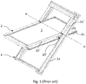
- the window comprises a sash 2 carrying a glazing in the form of a pane 3 and a frame 1.
- the window is intended to be built into a surface, which is inclined with respect to the horizontal, typically a roof, and the window will in the following be referred to as roof window.
- a hinge connection between the frame 1 and the sash 2.
- the hinge connection in Fig. 1 comprises a set of hinges, of which one hinge 10' is visible. The same operation as described above and from here on is also true for the type of hinge described in the Applicant's pending Danish patent application No. PA 2015 70717 filed on 06 November 2015 .
- hinges that include pivot hinges are for instance disclosed in Applicant's EP 1 038 083 B1 and EP 1 781 883 B1 , which are very versatile as regards operational areas and adaptation of components. Examples of roof windows incorporating such adapted hinges are shown in Applicant's published European patent applications EP 2 770 146 A1 and EP 2 770 149 A1 . From a closed position, the user operates the operating device of the window.
- the operating device typically comprises a handle (not shown) connected with the sash bottom member and/or an operating and locking assembly including a ventilation flap at the sash top member with a lock mechanism to interact with a striking plate on the frame top member.
- the hinge 10 exerts a moment on the sash 2, and in combination with the force, and hence moment, exerted by the user operating the operating device, the moment resulting from the weight of the sash 2 and pane 3 is overcome, along with any frictional forces present.
- the opening operation entails that the sash 2 is moved from a closed position to an open position as represented by Fig. 1 , in which the sash plane forms an opening angle with the frame plane.
- Closing the window from the open position entails the opposite movement of the sash 2. It is possible to position the sash 2 in a number of arbitrary opening positions, in which the sash 2 is held stable relative to the frame 1.
- the sash 2 is also able to be rotated substantially through 180° to allow cleaning of the outside of the pane 3 from the inside of the building in which the roof window is installed.
- the frame 1 and sash 2 is each formed by four members of which one frame side member 1a and one sash side member 2a are indicated.
- the sash 2 is openable with respect to the frame 1, as the sash 2 may be moved from a closed position, in which e.g. the sash side member 2a is substantially parallel with the frame side member 1a, to an open position, in which the sash side member 2a forms an angle with the frame side member 1a.
- the sash 2 rotates about a hinge axis ⁇ situated at the hinge connection. As indicated in Fig.
- the hinge axis ⁇ is located between a centre axis and the top of the roof window, preferably in the interval 1/3 to 2/3 of the distance between the centre axis and the top, most preferred substantially at 1/2 of the distance between the centre axis and the top.
- Other positions of the hinge axis are of course conceivable, for instance at the centre of the roof window.
- the roof window comprises a covering, including flashing members (not shown), cladding and covering elements of which a frame side covering element 1b' and sash side covering element 2b' are shown.
- the parts of the covering of the prior art roof window are connected to the frame and the sash, and to the hinge in a hinge and covering assembly as described in detail in the above-mentioned embodiment of EP 2 751 354 B1 .
- the prior art depictions of Figs 1 and 2 correspond to Applicant's published European patent application EP 3 252 250 A1 .
- connection of the frame side covering element 1b' and sash side covering element 2b' to the respective hinge part of the hinge 10' is carried out by a snap anchor 60', 70'.
- a cranked portion 2c' of the sash side covering element 2b' ensures a tight and flush transition between the sash side covering element 2b' and the frame side covering element 1b' in the closed position of the roof window.
- the movement pattern of the hinge allows that the sash side covering element 2b' is able to be retracted from its position under the frame side covering element 1b' during the opening movement of the sash 2 relative to the frame 1, and conversely, be inserted under the frame side covering element 1b' at the final stage of the closing movement.
- the roof window as comprising the frame 1, the sash 2 configured to be moved between a closed position and an open position, in which the sash 2 assumes an angle relative to the frame 1, and a set of hinges 10 corresponding to the components described in the above.
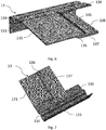
- the covering arrangement includes a frame side covering element generally designated 11 having a top portion 111 and an end edge 115.
- a sash side covering element generally designated 12 has a top portion 121 and an end edge 125 facing the end edge 115 of the frame side covering element 11 to form a gap 15. It is understood that the dimensions of the gap 15 will vary according to manufacturing tolerances, not only due to the covering arrangement itself but also of other components of the roof window. Furthermore, a gap is present between the two side covering elements 11, 12 both when the sash is open and closed, but in the following, the gap 15 will referred to as the space between the end edges 115, 125 of the respective frame and sash side covering elements.
- the covering arrangement is configured to cover at least the hinge (not shown) in the closed position of the sash 2, but also other components of the roof window such as the frame and sash side members.
- Each of the frame and sash side covering elements 11 and 12 has an external side facing the outdoor and an internal side facing the indoor.
- a central feature is that the covering arrangement includes at least one transition element 13, 14 connected to one of the frame side covering element 11 and the sash side covering element 12, near or at the respective end edge 115, 125 of the frame side covering element 11 or the sash side covering element 12.
- the at least one transition element includes a first transition element 13 connected to the sash side covering element 12 and having a first venturi portion 138 configured to face an interior side of the top portion 112 of the frame side covering element 11 in the closed position of the sash 2 to provide a constricted section between an inner channel section 17 and an outer channel section 16, nearest said cap 15.
- first venturi portion 138 is formed on a flange portion 137 of the first transition element 13, said flange portion 137 being formed in conjunction with an offsetting portion 136 adjacent a top portion 131 configured to abut an interior side of a top portion 121 of the sash side covering element 12 near the end edge 125 thereof.
- the first transition element may be formed in any suitable manner; however, it is preferred that the first transition element 13 as shown has an inner side portion 133 to match a corresponding inner side portion 123 of the sash side covering element 12. Furthermore, the first transition element 13 here has a drain portion 134 to match a corresponding drain portion 124 of the sash side covering element 12 and to be positioned in extension of a corresponding drain portion 114 of the frame side covering element 11. Finally, the first transition element 13 comprises an extended portion 139. The extended portion 139 ensures safe retention and guidance of the first transition element 13 in the cooperation with the sash and frame side covering elements 12, 11.
- the first transition element 13 comprises a breaker portion 135 configured to be located in the gap 15 between the respective end edges 115, 125 of the frame side covering element 11 and the sash side covering element 12 in the closed position of the sash 2.
- the breaker portion 135 here comprises a breaker back plate 135a extending at the end edge 125 of the sash side covering element 11 and protruding above the external side of the top portion 121 thereof.
- the breaker portion 135 comprises a plurality of breaker vanes 135b, preferably located at an angle to said breaker plate 135a, forming a corresponding plurality of breaker vane interstices 135c.
- a second transition element 14 is connected to the frame side covering element 11 and comprising a flat portion 141 and a second venturi portion 142 to be located opposite the first venturi portion 138 in the constricted section between the inner channel section 17 and the outer channel section 16 in the closed position of the sash 2.
- transition element or elements 13, 14 are provided separately from the sash and frame side covering elements 12, 11, a connection must be carried out in order to retain the components to each other. In principle, this could be performed by traditional mechanical techniques such as snap locking or friction engagement, possibly in support of adhesive connections, but these techniques do not create a roof window as claimed.
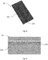
- each transition element 13, 14 is connected to the respective sash or frame side covering element 12, 11 by the use of a) engraving an interior surface of the covering element to provide an engraved surface with at least one cavity by subjecting the covering element to a laser beam at a polar angle; and b) attaching the at least one transition element 13, 14 to the covering element 12, 11 by introducing a portion of the transition element into the least one cavity. Details of such joining techniques are found in Applicant's co-pending international application No. PCT/DK2017/050356 .
- transition element or elements 13, 14 integrally with a snap anchor (corresponding to above prior art elements 60' and 70') configured to connect with a corresponding receiving section of a respective hinge part of the set of hinges.
- sealings may for instance include flaps forming one-way valves, allowing water present under the covering elements to exit but blocking the passage of water and other precipitation from entering.
- the invention further provides a method of providing a roof window with improved covering arrangement, comprising the steps of: providing a frame (1) and a sash (2), providing a covering arrangement including a frame side covering element (11) having a top portion (111) and an end edge (115), and a sash side covering element (12) having a top portion (121) and an end edge (125), providing at least one transition element (13, 14),
Landscapes
- Engineering & Computer Science (AREA)
- Architecture (AREA)
- Civil Engineering (AREA)
- Structural Engineering (AREA)
- Wing Frames And Configurations (AREA)
- Roof Covering Using Slabs Or Stiff Sheets (AREA)
- Door And Window Frames Mounted To Openings (AREA)
Claims (3)
- Dachfenster, insbesondere zur Installation in einer Schrägdachfläche, das Folgendes umfasst:einen Rahmen (1),einen Flügelrahmen (2), der dazu konfiguriert ist, zwischen einer geschlossenen Stellung und einer geöffneten Stellung, in der der Flügelrahmen (2) einen Winkel bezüglich des Rahmens (1) einnimmt, bewegt zu werden,einen Satz Scharniere (10), undeine Abdeckungsanordnung, die ein Rahmenseitenabdeckungselement (11) mit einem oberen Abschnitt (111) und einem Endrand (115) und ein Flügelrahmenseitenabdeckungselement (12) mit einem oberen Abschnitt (121) und einem Endrand (125), der zu dem Endrand (115) des Rahmenseitenabdeckungselements (11) zur Bildung eines Spalts (15) weist, umfasst, wobei die Abdeckungsanordnung dazu konfiguriert ist, zumindest die Scharniere (10) in der geschlossenen Stellung des Flügelrahmens (2) abzudecken, wobei die Abdeckungsanordnung mindestens ein separates Übergangselement (13, 14) umfasst, das mit dem Rahmenseitenabdeckungselement (11) oder dem Flügelrahmenseitenabdeckungselement (12) in der Nähe von oder an dem jeweiligen Endrand (115, 125) des Rahmenseitenabdeckungselements (11) oder des Flügelrahmenseitenabdeckungselements (12) verbunden ist, und das mindestens eine Übergangselement (13, 14) dazu konfiguriert ist, die Strömungsbedingungen an oder in der Nähe von dem Spalt (15) in der geschlossenen Stellung des Flügelrahmens (2) zu beeinflussen,dadurch gekennzeichnet, dassdas mindestens eine Übergangselement (13, 14) mit dem jeweiligen Flügelrahmen bzw. Rahmenseitenabdeckungselement (12, 11) durch Einsatz von a) Gravieren einer Innenfläche des Abdeckungselements zur Bereitstellung einer gravierten Fläche mit mindestens einem Hohlraum, indem das Abdeckungselement einem Laserstrahl mit einem Polarwinkel, al, ausgesetzt wird; und b) Anbringen des mindestens einen Übergangselements (13, 14) an dem Abdeckungselement (12, 11) durch Einführen eines Abschnitts des Übergangselements in den mindestens einen Hohlraum verbunden wird.
- Dachfenster nach Anspruch 1, wobei das mindestens eine Übergangselement (13, 14) integral mit einem Schnappanker ausgebildet ist, der zur Verbindung mit einem entsprechenden Aufnahmebereich eines jeweiligen Scharnierteils des Satzes von Scharnieren konfiguriert ist.
- Verfahren zur Bereitstellung eines Dachfensters mit einer verbesserten Abdeckungsanordnung, das die folgenden Schritte umfasst:Bereitstellen eines Rahmens (1) und eines Flügelrahmens (2),Bereitstellen einer Abdeckungsanordnung, die ein Rahmenseitenabdeckungselement (11) mit einem oberen Abschnitt (111) und einem Endrand (115) und ein Flügelrahmenseitenabdeckungselement (12) mit einem oberen Abschnitt (121) und einem Endrand (125) umfasst, Bereitstellen mindestens eines Übergangselements (13, 14),a) Gravieren einer Innenfläche mindestens eines der Abdeckungselemente (11, 12) zur Bereitstellung einer gravierten Fläche mit mindestens einem Hohlraum, indem das Abdeckungselement einem Laserstrahl mit einem Polarwinkel, al, ausgesetzt wird; undb) Anbringen des mindestens einen Übergangselements (13, 14) an dem Abdeckungselement (12, 11) durch Einführen eines Abschnitts des Übergangselements in den mindestens einen Hohlraum.
Priority Applications (1)
| Application Number | Priority Date | Filing Date | Title |
|---|---|---|---|
| PL20180346T PL3730716T3 (pl) | 2018-04-30 | 2019-04-29 | Okno dachowe z ulepszonym układem zakrywającym oraz sposób zapewniania okna dachowego z ulepszonym układem zakrywającym |
Applications Claiming Priority (2)
| Application Number | Priority Date | Filing Date | Title |
|---|---|---|---|
| DKPA201870257A DK180661B1 (en) | 2018-04-30 | 2018-04-30 | Roof window with covering arrangement |
| EP19171528.3A EP3564461B1 (de) | 2018-04-30 | 2019-04-29 | Dachfenster mit verbesserter abdeckungsanordnung |
Related Parent Applications (2)
| Application Number | Title | Priority Date | Filing Date |
|---|---|---|---|
| EP19171528.3A Division EP3564461B1 (de) | 2018-04-30 | 2019-04-29 | Dachfenster mit verbesserter abdeckungsanordnung |
| EP19171528.3A Division-Into EP3564461B1 (de) | 2018-04-30 | 2019-04-29 | Dachfenster mit verbesserter abdeckungsanordnung |
Publications (2)
| Publication Number | Publication Date |
|---|---|
| EP3730716A1 EP3730716A1 (de) | 2020-10-28 |
| EP3730716B1 true EP3730716B1 (de) | 2021-08-11 |
Family
ID=66323722
Family Applications (2)
| Application Number | Title | Priority Date | Filing Date |
|---|---|---|---|
| EP19171528.3A Active EP3564461B1 (de) | 2018-04-30 | 2019-04-29 | Dachfenster mit verbesserter abdeckungsanordnung |
| EP20180346.7A Active EP3730716B1 (de) | 2018-04-30 | 2019-04-29 | Dachfenster mit verbesserter abdeckungsanordnung und verfahren zur bereitstellung eines dachfensters mit verbesserter abdeckungsanordnung |
Family Applications Before (1)
| Application Number | Title | Priority Date | Filing Date |
|---|---|---|---|
| EP19171528.3A Active EP3564461B1 (de) | 2018-04-30 | 2019-04-29 | Dachfenster mit verbesserter abdeckungsanordnung |
Country Status (3)
| Country | Link |
|---|---|
| EP (2) | EP3564461B1 (de) |
| DK (1) | DK180661B1 (de) |
| PL (2) | PL3730716T3 (de) |
Families Citing this family (1)
| Publication number | Priority date | Publication date | Assignee | Title |
|---|---|---|---|---|
| CN112064853B (zh) * | 2020-07-31 | 2021-12-24 | 六安长城钢结构有限公司 | 一种钢结构旋转通风气楼 |
Family Cites Families (15)
| Publication number | Priority date | Publication date | Assignee | Title |
|---|---|---|---|---|
| GB1473570A (en) * | 1974-07-23 | 1977-05-18 | Albertsson H | Window assemblies |
| DE2628691A1 (de) * | 1976-06-25 | 1978-01-05 | Alfred Mueller | Dach-wohnraumfenster |
| FR2634510B1 (fr) * | 1988-07-21 | 1990-09-14 | Ferco Int Usine Ferrures | Pivot pour fenetre basculante ou oscillante de toiture |
| DK176024B1 (da) | 1997-11-11 | 2005-12-19 | Vkr Holding As | Hængselbeslag til et vippevindue |
| RU2184829C1 (ru) | 1998-04-07 | 2002-07-10 | Вкр Холдинг А/С | Мансардное окно с облицовочными элементами оконной коробки и створки |
| CN2795390Y (zh) | 2004-07-02 | 2006-07-12 | Vkr控股公司 | 铰链装置 |
| ES2560613T3 (es) | 2011-10-04 | 2016-02-22 | Vkr Holding A/S | Una ventana de techo con recubrimiento de moldura de impacto |
| DE202012006688U1 (de) * | 2012-07-10 | 2013-10-14 | Vkr Holding A/S | Dachfenster mit Abdeckmitteln für einen Rahmen |
| DK177808B1 (en) | 2013-02-22 | 2014-07-21 | Vkr Holding As | A roof window having an improved lifting device and hinge connection |
| DK178257B1 (en) | 2013-02-22 | 2015-10-12 | Vkr Holding As | A pivot hinge fitting and a roof window comprising such a hinge fitting |
| DE202014005241U1 (de) * | 2014-06-30 | 2014-08-11 | Joma-Polytec Gmbh | Kunststoff-Metall-Hybridteil |
| JP6287897B2 (ja) * | 2014-08-22 | 2018-03-07 | オムロン株式会社 | 照明装置、電子機器、フレーム構造、フレーム構造の製造方法 |
| DK179269B1 (en) | 2015-11-06 | 2018-03-19 | Vkr Holding As | A hinge for a roof window, and a roof window including a set of such hinges |
| DK179698B1 (en) | 2016-05-31 | 2019-04-01 | Vkr Holding A/S | A roof window with an improved hinge and covering assembly, and a method of providing such a hinge and covering assembly |
| DK179398B1 (en) * | 2016-10-31 | 2018-05-28 | Vkr Holding As | Method of providing a covering element and a covering element for covering a hinge part of a roof window |
-
2018
- 2018-04-30 DK DKPA201870257A patent/DK180661B1/en active IP Right Grant
-
2019
- 2019-04-29 EP EP19171528.3A patent/EP3564461B1/de active Active
- 2019-04-29 PL PL20180346T patent/PL3730716T3/pl unknown
- 2019-04-29 EP EP20180346.7A patent/EP3730716B1/de active Active
- 2019-04-29 PL PL19171528T patent/PL3564461T3/pl unknown
Also Published As
| Publication number | Publication date |
|---|---|
| EP3564461A3 (de) | 2020-01-01 |
| EP3730716A1 (de) | 2020-10-28 |
| PL3564461T3 (pl) | 2021-05-31 |
| PL3730716T3 (pl) | 2021-12-20 |
| DK201870257A1 (en) | 2019-11-12 |
| EP3564461A2 (de) | 2019-11-06 |
| EP3564461B1 (de) | 2020-12-23 |
| DK180661B1 (en) | 2021-11-11 |
Similar Documents
| Publication | Publication Date | Title |
|---|---|---|
| US6334283B1 (en) | Water resistant window frame | |
| RU2184828C1 (ru) | Открываемое окно с облицовочными элементами оконной коробки и створки | |
| US5590919A (en) | T-astragal and sleeve for door | |
| EP3333334B1 (de) | Dachfenster mit abdeckelement | |
| US20230392438A1 (en) | System and method for implementing an improved bi-fold shutter | |
| US6167661B1 (en) | Window, in particular for mounting in an inclined roof surface | |
| EP3730716B1 (de) | Dachfenster mit verbesserter abdeckungsanordnung und verfahren zur bereitstellung eines dachfensters mit verbesserter abdeckungsanordnung | |
| EP2202109B1 (de) | Rahmenlose und transparente Fahrzeugtür | |
| US6893083B2 (en) | Motor vehicle roof with a cover which can be moved to the rear over the roof skin | |
| US5428925A (en) | Fiberglass bulkhead door assembly | |
| EP1647660B1 (de) | Struktur einer Innenhoftür | |
| US20180112456A1 (en) | Jalousie Window Device | |
| WO1991011586A1 (en) | Window operator for use with awning window assembly | |
| EP3290614B1 (de) | Dachfenster mit verbesserten isolierungseigenschaften und mit einem satz an scharnieren | |
| EP3252250B1 (de) | Dachfenster mit einer verbesserten scharnier- und abdeckungsanordnung und verfahren zur bereitstellung solch einer scharnier- und abdeckungsanordnung | |
| JP3193307B2 (ja) | シャッター付き出窓 | |
| JPH025036Y2 (de) | ||
| KR0132148Y1 (ko) | 빗물가리개를 구비한 버스 도어 | |
| JPS6022221Y2 (ja) | オ−バ−ドアにおけるパネル接合部 | |
| JP6494324B2 (ja) | 建具 | |
| JPS6320787Y2 (de) | ||
| JP3096439B2 (ja) | 複合サッシの排水構造 | |
| KR20180000779U (ko) | 풀다운창이 결합된 미서기창 | |
| KR970003350Y1 (ko) | 교통신호제어기용 경첩(hinge) | |
| KR19990053343A (ko) | 빗물침입방지용 도어상단 웨더스트립의 구조 |
Legal Events
| Date | Code | Title | Description |
|---|---|---|---|
| PUAI | Public reference made under article 153(3) epc to a published international application that has entered the european phase |
Free format text: ORIGINAL CODE: 0009012 |
|
| STAA | Information on the status of an ep patent application or granted ep patent |
Free format text: STATUS: THE APPLICATION HAS BEEN PUBLISHED |
|
| AC | Divisional application: reference to earlier application |
Ref document number: 3564461 Country of ref document: EP Kind code of ref document: P |
|
| AK | Designated contracting states |
Kind code of ref document: A1 Designated state(s): AL AT BE BG CH CY CZ DE DK EE ES FI FR GB GR HR HU IE IS IT LI LT LU LV MC MK MT NL NO PL PT RO RS SE SI SK SM TR |
|
| STAA | Information on the status of an ep patent application or granted ep patent |
Free format text: STATUS: REQUEST FOR EXAMINATION WAS MADE |
|
| 17P | Request for examination filed |
Effective date: 20201211 |
|
| RBV | Designated contracting states (corrected) |
Designated state(s): AL AT BE BG CH CY CZ DE DK EE ES FI FR GB GR HR HU IE IS IT LI LT LU LV MC MK MT NL NO PL PT RO RS SE SI SK SM TR |
|
| GRAP | Despatch of communication of intention to grant a patent |
Free format text: ORIGINAL CODE: EPIDOSNIGR1 |
|
| STAA | Information on the status of an ep patent application or granted ep patent |
Free format text: STATUS: GRANT OF PATENT IS INTENDED |
|
| INTG | Intention to grant announced |
Effective date: 20210414 |
|
| GRAS | Grant fee paid |
Free format text: ORIGINAL CODE: EPIDOSNIGR3 |
|
| GRAA | (expected) grant |
Free format text: ORIGINAL CODE: 0009210 |
|
| STAA | Information on the status of an ep patent application or granted ep patent |
Free format text: STATUS: THE PATENT HAS BEEN GRANTED |
|
| AC | Divisional application: reference to earlier application |
Ref document number: 3564461 Country of ref document: EP Kind code of ref document: P |
|
| AK | Designated contracting states |
Kind code of ref document: B1 Designated state(s): AL AT BE BG CH CY CZ DE DK EE ES FI FR GB GR HR HU IE IS IT LI LT LU LV MC MK MT NL NO PL PT RO RS SE SI SK SM TR |
|
| REG | Reference to a national code |
Ref country code: CH Ref legal event code: EP |
|
| REG | Reference to a national code |
Ref country code: DE Ref legal event code: R096 Ref document number: 602019006856 Country of ref document: DE |
|
| REG | Reference to a national code |
Ref country code: IE Ref legal event code: FG4D Ref country code: AT Ref legal event code: REF Ref document number: 1419540 Country of ref document: AT Kind code of ref document: T Effective date: 20210915 |
|
| REG | Reference to a national code |
Ref country code: LT Ref legal event code: MG9D |
|
| REG | Reference to a national code |
Ref country code: NL Ref legal event code: MP Effective date: 20210811 |
|
| REG | Reference to a national code |
Ref country code: AT Ref legal event code: MK05 Ref document number: 1419540 Country of ref document: AT Kind code of ref document: T Effective date: 20210811 |
|
| PG25 | Lapsed in a contracting state [announced via postgrant information from national office to epo] |
Ref country code: ES Free format text: LAPSE BECAUSE OF FAILURE TO SUBMIT A TRANSLATION OF THE DESCRIPTION OR TO PAY THE FEE WITHIN THE PRESCRIBED TIME-LIMIT Effective date: 20210811 Ref country code: SE Free format text: LAPSE BECAUSE OF FAILURE TO SUBMIT A TRANSLATION OF THE DESCRIPTION OR TO PAY THE FEE WITHIN THE PRESCRIBED TIME-LIMIT Effective date: 20210811 Ref country code: RS Free format text: LAPSE BECAUSE OF FAILURE TO SUBMIT A TRANSLATION OF THE DESCRIPTION OR TO PAY THE FEE WITHIN THE PRESCRIBED TIME-LIMIT Effective date: 20210811 Ref country code: HR Free format text: LAPSE BECAUSE OF FAILURE TO SUBMIT A TRANSLATION OF THE DESCRIPTION OR TO PAY THE FEE WITHIN THE PRESCRIBED TIME-LIMIT Effective date: 20210811 Ref country code: FI Free format text: LAPSE BECAUSE OF FAILURE TO SUBMIT A TRANSLATION OF THE DESCRIPTION OR TO PAY THE FEE WITHIN THE PRESCRIBED TIME-LIMIT Effective date: 20210811 Ref country code: PT Free format text: LAPSE BECAUSE OF FAILURE TO SUBMIT A TRANSLATION OF THE DESCRIPTION OR TO PAY THE FEE WITHIN THE PRESCRIBED TIME-LIMIT Effective date: 20211213 Ref country code: NO Free format text: LAPSE BECAUSE OF FAILURE TO SUBMIT A TRANSLATION OF THE DESCRIPTION OR TO PAY THE FEE WITHIN THE PRESCRIBED TIME-LIMIT Effective date: 20211111 Ref country code: LT Free format text: LAPSE BECAUSE OF FAILURE TO SUBMIT A TRANSLATION OF THE DESCRIPTION OR TO PAY THE FEE WITHIN THE PRESCRIBED TIME-LIMIT Effective date: 20210811 Ref country code: BG Free format text: LAPSE BECAUSE OF FAILURE TO SUBMIT A TRANSLATION OF THE DESCRIPTION OR TO PAY THE FEE WITHIN THE PRESCRIBED TIME-LIMIT Effective date: 20211111 Ref country code: AT Free format text: LAPSE BECAUSE OF FAILURE TO SUBMIT A TRANSLATION OF THE DESCRIPTION OR TO PAY THE FEE WITHIN THE PRESCRIBED TIME-LIMIT Effective date: 20210811 |
|
| PG25 | Lapsed in a contracting state [announced via postgrant information from national office to epo] |
Ref country code: LV Free format text: LAPSE BECAUSE OF FAILURE TO SUBMIT A TRANSLATION OF THE DESCRIPTION OR TO PAY THE FEE WITHIN THE PRESCRIBED TIME-LIMIT Effective date: 20210811 Ref country code: GR Free format text: LAPSE BECAUSE OF FAILURE TO SUBMIT A TRANSLATION OF THE DESCRIPTION OR TO PAY THE FEE WITHIN THE PRESCRIBED TIME-LIMIT Effective date: 20211112 |
|
| PG25 | Lapsed in a contracting state [announced via postgrant information from national office to epo] |
Ref country code: NL Free format text: LAPSE BECAUSE OF FAILURE TO SUBMIT A TRANSLATION OF THE DESCRIPTION OR TO PAY THE FEE WITHIN THE PRESCRIBED TIME-LIMIT Effective date: 20210811 |
|
| PG25 | Lapsed in a contracting state [announced via postgrant information from national office to epo] |
Ref country code: DK Free format text: LAPSE BECAUSE OF FAILURE TO SUBMIT A TRANSLATION OF THE DESCRIPTION OR TO PAY THE FEE WITHIN THE PRESCRIBED TIME-LIMIT Effective date: 20210811 |
|
| REG | Reference to a national code |
Ref country code: DE Ref legal event code: R097 Ref document number: 602019006856 Country of ref document: DE |
|
| PG25 | Lapsed in a contracting state [announced via postgrant information from national office to epo] |
Ref country code: SM Free format text: LAPSE BECAUSE OF FAILURE TO SUBMIT A TRANSLATION OF THE DESCRIPTION OR TO PAY THE FEE WITHIN THE PRESCRIBED TIME-LIMIT Effective date: 20210811 Ref country code: SK Free format text: LAPSE BECAUSE OF FAILURE TO SUBMIT A TRANSLATION OF THE DESCRIPTION OR TO PAY THE FEE WITHIN THE PRESCRIBED TIME-LIMIT Effective date: 20210811 Ref country code: RO Free format text: LAPSE BECAUSE OF FAILURE TO SUBMIT A TRANSLATION OF THE DESCRIPTION OR TO PAY THE FEE WITHIN THE PRESCRIBED TIME-LIMIT Effective date: 20210811 Ref country code: EE Free format text: LAPSE BECAUSE OF FAILURE TO SUBMIT A TRANSLATION OF THE DESCRIPTION OR TO PAY THE FEE WITHIN THE PRESCRIBED TIME-LIMIT Effective date: 20210811 Ref country code: CZ Free format text: LAPSE BECAUSE OF FAILURE TO SUBMIT A TRANSLATION OF THE DESCRIPTION OR TO PAY THE FEE WITHIN THE PRESCRIBED TIME-LIMIT Effective date: 20210811 Ref country code: AL Free format text: LAPSE BECAUSE OF FAILURE TO SUBMIT A TRANSLATION OF THE DESCRIPTION OR TO PAY THE FEE WITHIN THE PRESCRIBED TIME-LIMIT Effective date: 20210811 |
|
| PLBE | No opposition filed within time limit |
Free format text: ORIGINAL CODE: 0009261 |
|
| STAA | Information on the status of an ep patent application or granted ep patent |
Free format text: STATUS: NO OPPOSITION FILED WITHIN TIME LIMIT |
|
| 26N | No opposition filed |
Effective date: 20220512 |
|
| PG25 | Lapsed in a contracting state [announced via postgrant information from national office to epo] |
Ref country code: IT Free format text: LAPSE BECAUSE OF FAILURE TO SUBMIT A TRANSLATION OF THE DESCRIPTION OR TO PAY THE FEE WITHIN THE PRESCRIBED TIME-LIMIT Effective date: 20210811 |
|
| REG | Reference to a national code |
Ref country code: CH Ref legal event code: PL |
|
| REG | Reference to a national code |
Ref country code: BE Ref legal event code: MM Effective date: 20220430 |
|
| PG25 | Lapsed in a contracting state [announced via postgrant information from national office to epo] |
Ref country code: MC Free format text: LAPSE BECAUSE OF FAILURE TO SUBMIT A TRANSLATION OF THE DESCRIPTION OR TO PAY THE FEE WITHIN THE PRESCRIBED TIME-LIMIT Effective date: 20210811 Ref country code: LU Free format text: LAPSE BECAUSE OF NON-PAYMENT OF DUE FEES Effective date: 20220429 Ref country code: LI Free format text: LAPSE BECAUSE OF NON-PAYMENT OF DUE FEES Effective date: 20220430 Ref country code: CH Free format text: LAPSE BECAUSE OF NON-PAYMENT OF DUE FEES Effective date: 20220430 |
|
| PG25 | Lapsed in a contracting state [announced via postgrant information from national office to epo] |
Ref country code: BE Free format text: LAPSE BECAUSE OF NON-PAYMENT OF DUE FEES Effective date: 20220430 |
|
| PG25 | Lapsed in a contracting state [announced via postgrant information from national office to epo] |
Ref country code: IE Free format text: LAPSE BECAUSE OF NON-PAYMENT OF DUE FEES Effective date: 20220429 |
|
| PG25 | Lapsed in a contracting state [announced via postgrant information from national office to epo] |
Ref country code: MK Free format text: LAPSE BECAUSE OF FAILURE TO SUBMIT A TRANSLATION OF THE DESCRIPTION OR TO PAY THE FEE WITHIN THE PRESCRIBED TIME-LIMIT Effective date: 20210811 Ref country code: CY Free format text: LAPSE BECAUSE OF FAILURE TO SUBMIT A TRANSLATION OF THE DESCRIPTION OR TO PAY THE FEE WITHIN THE PRESCRIBED TIME-LIMIT Effective date: 20210811 |
|
| PG25 | Lapsed in a contracting state [announced via postgrant information from national office to epo] |
Ref country code: HU Free format text: LAPSE BECAUSE OF FAILURE TO SUBMIT A TRANSLATION OF THE DESCRIPTION OR TO PAY THE FEE WITHIN THE PRESCRIBED TIME-LIMIT; INVALID AB INITIO Effective date: 20190429 |
|
| PG25 | Lapsed in a contracting state [announced via postgrant information from national office to epo] |
Ref country code: MT Free format text: LAPSE BECAUSE OF FAILURE TO SUBMIT A TRANSLATION OF THE DESCRIPTION OR TO PAY THE FEE WITHIN THE PRESCRIBED TIME-LIMIT Effective date: 20210811 |
|
| PGFP | Annual fee paid to national office [announced via postgrant information from national office to epo] |
Ref country code: FR Payment date: 20250321 Year of fee payment: 7 |
|
| PGFP | Annual fee paid to national office [announced via postgrant information from national office to epo] |
Ref country code: GB Payment date: 20250306 Year of fee payment: 7 |
|
| PGFP | Annual fee paid to national office [announced via postgrant information from national office to epo] |
Ref country code: DE Payment date: 20250305 Year of fee payment: 7 |
|
| PG25 | Lapsed in a contracting state [announced via postgrant information from national office to epo] |
Ref country code: TR Free format text: LAPSE BECAUSE OF FAILURE TO SUBMIT A TRANSLATION OF THE DESCRIPTION OR TO PAY THE FEE WITHIN THE PRESCRIBED TIME-LIMIT Effective date: 20210811 |
|
| PG25 | Lapsed in a contracting state [announced via postgrant information from national office to epo] |
Ref country code: SI Free format text: LAPSE BECAUSE OF FAILURE TO SUBMIT A TRANSLATION OF THE DESCRIPTION OR TO PAY THE FEE WITHIN THE PRESCRIBED TIME-LIMIT Effective date: 20210811 |
|
| PGFP | Annual fee paid to national office [announced via postgrant information from national office to epo] |
Ref country code: PL Payment date: 20260313 Year of fee payment: 8 |