EP3730845A1 - Unité intérieure de plafond pour climatiseur - Google Patents
Unité intérieure de plafond pour climatiseur Download PDFInfo
- Publication number
- EP3730845A1 EP3730845A1 EP18890162.3A EP18890162A EP3730845A1 EP 3730845 A1 EP3730845 A1 EP 3730845A1 EP 18890162 A EP18890162 A EP 18890162A EP 3730845 A1 EP3730845 A1 EP 3730845A1
- Authority
- EP
- European Patent Office
- Prior art keywords
- wire
- disposed
- roller
- drum
- unit
- Prior art date
- Legal status (The legal status is an assumption and is not a legal conclusion. Google has not performed a legal analysis and makes no representation as to the accuracy of the status listed.)
- Granted
Links
Images







Classifications
-
- F—MECHANICAL ENGINEERING; LIGHTING; HEATING; WEAPONS; BLASTING
- F24—HEATING; RANGES; VENTILATING
- F24F—AIR-CONDITIONING; AIR-HUMIDIFICATION; VENTILATION; USE OF AIR CURRENTS FOR SCREENING
- F24F1/00—Room units for air-conditioning, e.g. separate or self-contained units or units receiving primary air from a central station
- F24F1/0007—Indoor units, e.g. fan coil units
- F24F1/0011—Indoor units, e.g. fan coil units characterised by air outlets
-
- F—MECHANICAL ENGINEERING; LIGHTING; HEATING; WEAPONS; BLASTING
- F24—HEATING; RANGES; VENTILATING
- F24F—AIR-CONDITIONING; AIR-HUMIDIFICATION; VENTILATION; USE OF AIR CURRENTS FOR SCREENING
- F24F13/00—Details common to, or for air-conditioning, air-humidification, ventilation or use of air currents for screening
- F24F13/08—Air-flow control members, e.g. louvres, grilles, flaps or guide plates
- F24F13/082—Grilles, registers or guards
- F24F13/084—Grilles, registers or guards with mounting arrangements, e.g. snap fasteners for mounting to the wall or duct
-
- F—MECHANICAL ENGINEERING; LIGHTING; HEATING; WEAPONS; BLASTING
- F24—HEATING; RANGES; VENTILATING
- F24F—AIR-CONDITIONING; AIR-HUMIDIFICATION; VENTILATION; USE OF AIR CURRENTS FOR SCREENING
- F24F13/00—Details common to, or for air-conditioning, air-humidification, ventilation or use of air currents for screening
- F24F13/08—Air-flow control members, e.g. louvres, grilles, flaps or guide plates
- F24F13/082—Grilles, registers or guards
- F24F13/085—Grilles, registers or guards including an air filter
-
- F—MECHANICAL ENGINEERING; LIGHTING; HEATING; WEAPONS; BLASTING
- F24—HEATING; RANGES; VENTILATING
- F24F—AIR-CONDITIONING; AIR-HUMIDIFICATION; VENTILATION; USE OF AIR CURRENTS FOR SCREENING
- F24F13/00—Details common to, or for air-conditioning, air-humidification, ventilation or use of air currents for screening
- F24F13/08—Air-flow control members, e.g. louvres, grilles, flaps or guide plates
- F24F13/10—Air-flow control members, e.g. louvres, grilles, flaps or guide plates movable, e.g. dampers
-
- F—MECHANICAL ENGINEERING; LIGHTING; HEATING; WEAPONS; BLASTING
- F24—HEATING; RANGES; VENTILATING
- F24F—AIR-CONDITIONING; AIR-HUMIDIFICATION; VENTILATION; USE OF AIR CURRENTS FOR SCREENING
- F24F13/00—Details common to, or for air-conditioning, air-humidification, ventilation or use of air currents for screening
- F24F13/20—Casings or covers
-
- F—MECHANICAL ENGINEERING; LIGHTING; HEATING; WEAPONS; BLASTING
- F24—HEATING; RANGES; VENTILATING
- F24F—AIR-CONDITIONING; AIR-HUMIDIFICATION; VENTILATION; USE OF AIR CURRENTS FOR SCREENING
- F24F13/00—Details common to, or for air-conditioning, air-humidification, ventilation or use of air currents for screening
- F24F13/28—Arrangement or mounting of filters
-
- F—MECHANICAL ENGINEERING; LIGHTING; HEATING; WEAPONS; BLASTING
- F24—HEATING; RANGES; VENTILATING
- F24F—AIR-CONDITIONING; AIR-HUMIDIFICATION; VENTILATION; USE OF AIR CURRENTS FOR SCREENING
- F24F1/00—Room units for air-conditioning, e.g. separate or self-contained units or units receiving primary air from a central station
- F24F1/0007—Indoor units, e.g. fan coil units
- F24F1/0043—Indoor units, e.g. fan coil units characterised by mounting arrangements
- F24F1/0047—Indoor units, e.g. fan coil units characterised by mounting arrangements mounted in the ceiling or at the ceiling
-
- F—MECHANICAL ENGINEERING; LIGHTING; HEATING; WEAPONS; BLASTING
- F24—HEATING; RANGES; VENTILATING
- F24F—AIR-CONDITIONING; AIR-HUMIDIFICATION; VENTILATION; USE OF AIR CURRENTS FOR SCREENING
- F24F13/00—Details common to, or for air-conditioning, air-humidification, ventilation or use of air currents for screening
- F24F13/08—Air-flow control members, e.g. louvres, grilles, flaps or guide plates
- F24F13/10—Air-flow control members, e.g. louvres, grilles, flaps or guide plates movable, e.g. dampers
- F24F13/14—Air-flow control members, e.g. louvres, grilles, flaps or guide plates movable, e.g. dampers built up of tilting members, e.g. louvre
- F24F13/1426—Air-flow control members, e.g. louvres, grilles, flaps or guide plates movable, e.g. dampers built up of tilting members, e.g. louvre characterised by actuating means
- F24F2013/1453—Air-flow control members, e.g. louvres, grilles, flaps or guide plates movable, e.g. dampers built up of tilting members, e.g. louvre characterised by actuating means with cables, e.g. bowden cables
-
- F—MECHANICAL ENGINEERING; LIGHTING; HEATING; WEAPONS; BLASTING
- F24—HEATING; RANGES; VENTILATING
- F24F—AIR-CONDITIONING; AIR-HUMIDIFICATION; VENTILATION; USE OF AIR CURRENTS FOR SCREENING
- F24F13/00—Details common to, or for air-conditioning, air-humidification, ventilation or use of air currents for screening
- F24F13/20—Casings or covers
- F24F2013/207—Casings or covers with control knobs; Mounting controlling members or control units therein
Definitions
- the present disclosure relates to a ceiling-type indoor unit of an air-conditioner, and more particularly, to a ceiling-type indoor unit in which an intake grille is automatically lowered and lifted.
- air-conditioners include a compressor, a condenser, an evaporator, and an expander and supply cold air or warm air to a building or a room using an air conditioning cycle.
- Air-conditioners are structurally classified as a separation type in which a compressor is disposed outdoors and an integrated type in which a compressor is integrally manufactured.
- an indoor heat exchanger is installed in an indoor unit and an outdoor heat exchanger and a compressor are installed in an outdoor unit and the two devices separated from each other are connected with a refrigerant pipe.
- Integrated type air-conditioners include a window type air-conditioner installed directly by hanging a device on a window and a duct type air-conditioner installed outside a room by connecting an intake duct and a discharge duct.
- the separation type air-conditioners are generally classified depending on an installation form of the indoor unit.
- An air-conditioner whose indoor unit is installed vertically in an indoor space is called a stand-type air-conditioner
- an air-conditioner whose indoor unit is installed on a wall in a room is called a wall-mounted air-conditioner
- an air-conditioner whose indoor unit installed on a ceiling in a room is called a ceiling-type indoor unit.
- the intake grille is arranged to face a floor.
- a filter for filtering foreign matter in the indoor air may be disposed on the intake grille and may be separated for cleaning. A user needs to periodically remove the intake grille from the case to clean the filter.
- An intake grille disposed in the ceiling-type indoor unit of the related art has a structure that is open, while rotating to one side.
- the intake grille since the intake grille is disposed on the ceiling of the room, the user has to climb on a structure such as a chair to separate the intake grille.
- the present disclosure provides a ceiling-type indoor unit of an air-conditioner in which an entire intake grille is lifted or lowered by simultaneously winding or unwinding two pairs of wires.
- the present disclosure provides a ceiling-type indoor unit of an air-conditioner having a structure capable of simultaneously unwinding or winding four wires using two motors.
- the present disclosure provides a ceiling-type indoor unit of an air-conditioner in which an intake grille is prevented from falling when lifted or lowered.
- the present disclosure provides a ceiling-type indoor unit of an air-conditioner shaking is minimized when an intake grille is lifted or lowered.
- the present disclosure provides a ceiling-type indoor unit of an air-conditioner in which shaking is minimized when an intake grille is lifted or lowered.
- the present disclosure provides a ceiling-type indoor unit of an air-conditioner in which separation of foreign matter attached to a filter is minimized when the intake grille is lifted or lowered.
- an intake grille may be simultaneously lifted or lowered using two motors, while the intake grille is supported at four points through four wires.
- one motor controls a pair of wires arranged on one side of the intake grille, a height variation on one side of the intake grille may be minimized.
- the other three wires may support the intake grille, thereby preventing the intake grille from falling.
- a ceiling-type indoor unit of an air-conditioner includes: a case installed on an interior ceiling in a suspended manner and having an inlet and an outlet provided downward; an intake grille disposed to be separable from the case, covering the inlet of the case, and moved in an up-down direction from the case; a 1-1 wire disposed on one side with respect to the intake grille and having a lower end fixed to the intake grille; a 1-2 wire disposed on one side with respect to the intake grille and having a lower end fixed to the intake grille; a 2-1 wire disposed on the other side with respect to the intake grille and having a lower end fixed to the intake grille; a 2-2 wire disposed on the other side with respect to the intake grille and having a lower end fixed to the intake grille; a first unit disposed in the case, coupled to each of upper ends of the 1-1 wire and the 1-2 wire, and lifting or lowering one side of the intake grille by simultaneously winding or unwinding the 1-1 wire and the 1-2
- the first unit and the second unit may be disposed to face each other based on the center O of the intake grille.
- the first drum may include: a first zone formed on the outer circumferential surface of the first drum, allowing the upper end of the 1-1 wire to be fixed thereto, and allowing the 1-1 wire to be wound therearound; and a second zone formed on the outer circumferential surface of the first drum, allowing the upper end of the 1-2 wire to be fixed thereto, and allowing the 1-2 wire to be wound therearound, and the second drum may include: a first zone formed on the outer circumferential surface of the second drum, allowing the upper end of the 2-1 wire to be fixed thereto, and allowing the 2-1 wire to be wound therearound; and a second zone formed on the outer circumferential surface of the second drum, allowing the upper end of the 2-2 wire to be fixed thereto, and allowing the 2-2 wire to be wound therearound.
- the first drum may further include: a first partition partitioning the first zone and the second zone, wherein the first partition protrudes from the outer circumferential surface of each drum
- the second drum may further include: a second partition partitioning the first zone and the second zone, wherein the second partition protrudes from the outer circumferential surface of each drum.
- the first partition may protrude in a radial direction of the first drum, may be formed along a circumferential direction of the first drum, and may be perpendicular to a motor shaft of the first drum motor
- the second partition may protrude in a radial direction of the second drum, may be formed along a circumferential direction of the second drum, and may be perpendicular to a motor shaft of the second drum motor.
- the first zone and the second zone of the first drum may be arranged in parallel, and the first zone and the second zone of the second drum may be arranged in parallel.
- the first drum may form an axial center rotated by the first drum motor
- the second drum may form an axial center rotated by the second drum motor
- the axial center of the first drum and the axial center of the second drum may be arranged in a line.
- the upper end of the 1-1 wire fixed to the first zone and the upper end of the 1-2 wire fixed to the second zone may be symmetrical with respect to the axial center of the first drum.
- the upper end of the 2-1 wire fixed to the first zone and the upper end of the 2-2 wire fixed to the second zone may be symmetrical with respect to the axial center of the second drum.
- the first unit may further include: a first unit case in which the first drum and the first drum motor are installed, the first unit case may be fixed to inside of the case, and the second unit may further include a second unit case in which the second drum and the second drum motor are installed, the second unit case may be fixed inside of the case, the first unit case may include a first hole through which the 1-1 wire passes; and a second hole through which the 1-2 wire passes; and the second unit case may include a first hole through which the 2-1 wire passes; and a second hole through which the 2-2 wire passes, and an interval between the first hole and the second hole of the first unit case may be equal to an interval between the first hole and the second hole of the second unit case.
- the first hole and the second hole of the first unit case may be open downward, and the first hole and the second hole of the second unit case may be open downward.
- the first hole and the second hole of the first unit case may be disposed on a sidewall of the first unit case, the first hole and the second hole of the first unit case may be disposed to face in mutually opposite directions, the first hole and the second hole of the second unit case may be disposed on a sidewall of the second unit case, and the first hole and the second hole of the second unit case may be disposed to face in mutually opposite directions.
- the ceiling-type indoor unit may further include: a first wire guider disposed at the case, supporting the 1-1 wire, and located above the intake grille; a second wire guider disposed at the case, supporting the 1-2 wire, and located above the intake grille; a third wire guider disposed at the case, supporting the 2-1 wire, and located above the intake grille; and a fourth wire guider disposed at the case, supporting the 2-2 wire, and located above the intake grille, wherein the first hole of the first unit case may be disposed to face the first wire guider, the second hole of the first unit case may be disposed to face the second wire guider, the first hole of the second unit case may be disposed to face the third wire guider, and the second hole of the second unit case may be disposed to face the fourth wire guider.
- the ceiling-type indoor unit may further include: a first rotation detecting device disposed at the first unit and detecting rotation of the first drum; and a second rotation detecting device disposed at the second unit and detecting rotation of the second drum, wherein the first rotation detecting device may include: a rotation detecting factor disposed at the first drum and rotating together when the first drum rotates; a sensor disposed to be spaced apart from the rotation detecting factor and detecting rotation of the rotation detecting factor; and a printed circuit board (PCB) on which the sensor is disposed, and the second rotation detecting device may include: a rotation detecting factor disposed at the second drum and rotating together when the second drum rotates; a sensor disposed to be spaced apart from the rotation detecting factor and detecting rotation of the rotation detecting factor; and a PCB on which the sensor is disposed.
- the first rotation detecting device may include: a rotation detecting factor disposed at the first drum and rotating together when the first drum rotates; a sensor disposed to be spaced apart from the rotation detecting factor
- Each sensor may be an infrared sensor, the rotation detecting factor may be a sawtooth protruding outward in a radial direction of the drum, and the sensor may detect an infrared signal controlled by the sawtooth.
- the sensor may include a light emitting unit and a light receiving unit
- the rotation detecting device may further include: a sensor installation portion in which the light emitting unit and the light receiving unit are installed; and a slot formed at the sensor mounting portion and formed to be concave to allow the rotation detecting factor to pass therethrough, wherein the light emitting unit and the light receiving unit may be arranged on mutually opposite sides based on the slot.
- the first unit may further include: a 1-1 roller box disposed on one side with respect to the first drum, disposed to be penetrated by the 1-1 wire, and aligning a position of the 1-1 wire when the 1-1 wire is wound or unwound; a 1-2 roller box disposed on the other side with respect to the first drum, disposed to be penetrated by the 1-2 wire, and aligning a position of the 1-2 wire when the 1-2 wire is wound or unwound; and a first rotation amount detecting device detecting a rotation amount of the first drum, and the second unit may further include: a 2-1 roller box disposed on one side with respect to the second drum, disposed to be penetrated by the 2-1 wire, and aligning a position of the 2-1 wire when the 2-1 wire is wound or unwound; a 2-2 roller box disposed on the other side with respect to the second drum, disposed to be penetrated by the 2-2 wire, and aligning a position of the 2-2 wire when the 2-2 wire is wound or unwound;
- the first drum may include: a first drum body having a cylindrical shape and allowing upper ends of the 1-1 wire and the 1-2 wire to be fixed thereto; a first zone disposed on an outer circumferential surface of the first drum body and allowing the 1-1 wire to wind therearound; a second zone disposed on an outer circumferential surface of the first drum body and allowing the 1-2 wire to wind therearound; a partition protruding outward from the first drum body and partitioning the first zone and the second zone; a 1-1 barrier protruding outward from the first drum body and preventing the 1-1 wire from escaping to outside of the first zone; and a 1-2 barrier protruding outward from the first drum body and preventing the 1-2 wire from escaping to outside of the second zone, and the second drum may include: a second drum body having a cylindrical shape and allowing upper ends of the 2-1 wire and the 2-2 wire to be fixed thereto; a first zone disposed on an outer circumferential surface of the second drum body and allowing the 2-1 wire to wind
- the ceiling-type indoor unit may further includes: a first unit case disposed in the case and allowing the first drum, the first drum motor, the 1-1 roller box, and the 1-2 roller box to be installed therein; a second unit case disposed in the case and allowing the second drum, the second drum motor, the 2-1 roller box, and the 2-2 roller box to be installed therein; a first hole formed in the first unit case and penetrated by the 1-1 wire; a second hole formed in the first unit case and penetrated by the 1-2wire; a first hole formed in the second unit case and penetrated by the 2-1 wire; and a second hole formed in the second unit case and penetrated by the 2-2 wire, wherein the first hole and the second hole of the first unit case are disposed on a side wall of the first unit case, the first hole and the second hole of the first unit case are arranged to face in mutually opposite directions, the first hole and the second hole of the second unit case are disposed on a side wall of the second unit case, and the first hole and the second hole of the
- the ceiling-type indoor unit may further include: a first wire guider disposed in the case, supporting the 1-1 wire, and located above the intake grille; a second wire guider disposed in the case, supporting the 1-2 wire, and located above the intake grille; a third wire guider disposed in the case, supporting the 2-1 wire, and located above the intake grille; and a fourth wire guider disposed in the case, supporting the 2-2 wire, and located above the intake grille, wherein the first hole of the first unit case is disposed to face the first wire guider, the second hole of the first unit case is disposed to face the second wire guider, the first hole of the second unit case is disposed to face the third wire guider, and the second hole of the second unit case is disposed to face the fourth wire guider.
- the 1-1 roller box and the 1-2 roller box may be disposed symmetrically with respect to the motor shaft of the first drum motor, and the 2-1 roller box and the 2-2 roller box may be disposed symmetrically with respect to the motor shaft of the second drum motor.
- the ceiling-type indoor unit of an air-conditioner has one or more advantages as follows.
- two pairs of wires may be simultaneously wound or unwound through two drum motors operating the first drum and the second drum, respectively.
- the intake griller since the intake griller is supported at four points through four wires, the intake grille may be stably lifted or lowered.
- the elevator since the elevator is configured to simultaneously wind or unwind four wires and two motors are used, a material cost required for manufacturing may be reduced and controlling may be simplified.
- two wires since the two wires are fixed to one drum, two wires may be simultaneously wound or unwound.
- the intake grille since the intake grille is maintained in a state of being in close contact with the front body, while being supported by four wires, the intake grille may be lowered immediately when the elevator operates.
- each wire is wound or unwound in each region of the drum, thereby uniformly controlling a length and speed of the wires.
- the rotation amount detecting device for detecting a rotation amount and a rotation speed of the drum is disposed at each of the first unit and the second unit, two drum motors may be controlled in the same manner.
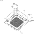
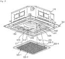
- FIG. 1 is a perspective view of an indoor unit of an air-conditioner according to an embodiment of the present disclosure.
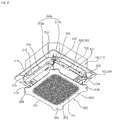
- FIG. 2 is an exemplary view of an operation of FIG. 1 .
- FIG. 3 is a cross-sectional view of FIG. 1 .
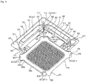
- FIG. 4 is an exploded perspective view of a front panel of FIG. 1 .
- FIG. 5 is a plan view showing an arrangement of the front panel and an elevator of FIG. 1 .
- FIG. 6 is a bottom view of the front panel shown in FIG. 1 .
- FIG. 7 is a bottom perspective view of an elevator of FIG. 2 .
- FIG. 8 is a bottom view of the front panel and the elevator of FIG. 2 .
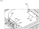
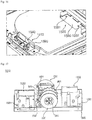
- FIG. 9 is a perspective view showing an internal structure of the elevator of FIG. 2 .
- FIG. 1 is a perspective view of an indoor unit of an air-conditioner according to an embodiment of the present disclosure.
- FIG. 2 is an exemplary view of an operation of FIG. 1 .
- FIG. 3 is
- FIG. 10 is a plan view of FIG. 9 .
- FIG. 11 is an exemplary view of an operation of an elevator according to a first embodiment of the present disclosure.
- FIG. 12 is an exemplary view showing an installation structure of a wire according to the first embodiment of the present disclosure.
- FIG. 13 is a plan view of an intake grille shown in FIG. 4 .
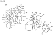
- FIG. 14 is an exploded perspective view of a wire guider shown in FIG. 2 .
- An indoor unit of an air-conditioner includes a case 100 including an inlet 101 and an outlet 102, an indoor heat exchanger 130 disposed in the case 100, and an indoor blower fan 140 disposed in the case 100 and causing air to flow to the inlet 101 and the outlet 102.
- both the inlet 101 and the outlet 102 are formed on a bottom surface.
- the indoor unit intakes air from the bottom and then discharges air to the bottom.
- the case 100 further includes an intake grille 320 disposed to face a floor of a room, and an elevator 500 lifting or lowering the intake grille 320 in a vertical direction is disposed in the case 100.
- the elevator 500 When a user's operation signal is received, the elevator 500 may be operated, four wires 511, 512, 521, and 522 may be simultaneously unwound or wound by the operation of the elevator 500, and the intake grille 320 coupled to the wires 511, 512, 521, and 522 may be moved in the vertical direction.
- a structure of the elevator 500 for lifting and lowering the intake grille 320 will be described later in detail.
- the case 100 includes a case housing 110 and a front panel 300.
- the case housing 100 is installed to hang on the ceiling of a room through a hanger (not shown) and a lower side thereof is open.
- the front panel 300 covers the open surface of the case housing 110, is disposed to face a floor of the room, is exposed to the room, and has the inlet 101 and the outlet 102.
- the case 100 may be implemented in various ways depending on a production form, and the configuration of the case 100 does not limit the spirit of the present disclosure.
- the inlet 101 and the outlet 102 are both disposed on the front panel 300.
- only the front panel 300 is exposed to the outside and the case housing 110 is embedded and hidden in the ceiling.
- the front panel 300 is disposed below the case housing 110.
- the intake grille 320 is located inside the front panel 300.
- the intake grille 320 is located on the same horizontal line as the front panel 300 and is located lower than the case housing 110.
- Both the inlet 101 and the outlet 102 are open downward.
- the inlet 101 and the outlet 102 are located lower than the indoor heat exchanger 130 and the indoor blower fan 140.
- the inlet 101 is disposed at the center of the front panel 300, and the outlet 102 is disposed outside the inlet 101.
- the number of the inlet 101 or the number of the outlet 102 is irrelevant to the spirit of the present disclosure.
- one inlet 101 is provided and a plurality of outlets 102 are disposed.
- the inlet 101 has a square shape in a bottom view, and four outlets 102 are provided and spaced apart from each edge of the inlet 101 by a predetermined interval.
- the indoor heat exchanger 130 is disposed between the inlet 101 and the outlet 102 and partitions the case 100 into an inner side and an outer side.
- the indoor heat exchanger 130 is disposed vertically in this embodiment.
- An indoor blower fan 140 is located on an inner side of the indoor heat exchanger 130.
- the indoor heat exchanger may have an overall shape of " ⁇ ", and some sections thereof may be separated.
- the indoor heat exchanger 130 is disposed such that air discharged from the indoor blower fan 140 enters vertically.
- a drain pan 132 is installed in the case 100, and the indoor heat exchanger 130 is mounted on the drain pan 132. Condensate water generated in the indoor heat exchanger 130 may flow to the drain pan 132 and be subsequently stored therein.
- a drain pump (not shown) for discharging collected condensate water to the outside is disposed in the drain pan 132.
- the drain pan 132 may have an inclined surface having directionality to collect and store condensate water flowing from the indoor heat exchanger 130 to one side.
- the indoor blower fan 140 is located in the case 100 and is disposed above the inlet 101.
- the indoor blower fan 140 is a centrifugal blower that intakes air to the center and discharges air in a circumferential direction.
- the indoor blower fan 140 includes a bell mouse 142, a fan 144, and a fan motor 146.
- the bell mouse 142 is disposed above the intake grille 320 and located below the fan 144.
- the bell mouse 142 guides air passing through the intake grille 320 to the fan 144.
- the fan motor 146 rotates the fan 144.
- the fan motor 146 is fixed to the case housing 110.
- the fan motor 146 is disposed above the fan 144. At least a portion of the fan motor 146 is located higher than the fan 144.
- a motor shaft of the fan motor 146 is disposed to face a lower side, and the fan 144 is coupled to the motor shaft.
- the indoor heat exchanger 130 is located outside the edge of the fan 144. At least portions of the fan 144 and the indoor heat exchanger 130 are disposed on the same horizontal line. At least a portion of the bell mouse 142 is inserted into the fan 144. At least a portion of the bell mouse 142 overlaps the fan 144 in the up-down direction.
- the indoor heat exchanger 130 is disposed in the case housing 110 and partitions an inner space of the case housing 110 into an inner side and an outer side.
- An inner space surrounded by the indoor heat exchanger 130 is defined as an intake flow path 103, and an outer space of the indoor heat exchanger 130 is defined as a discharge flow path 104.
- the indoor blower fan 140 is disposed at the intake flow path 103.
- the discharge flow path 104 is between the outside of the indoor heat exchanger 130 and a side wall of the case housing 110.
- the intake flow path 103 is an inner side surrounded by " ⁇ " of the indoor heat exchanger
- the discharge flow path 104 is an outer side surrounded by " ⁇ " of the indoor heat exchanger.
- the intake flow path 103 communicates with the inlet 101, and the discharge flow path 104 communicates with the outlet 103.
- a flow direction of air is switched 180 degrees based on the indoor heat exchanger 130.
- the inlet 101 and the outlet 102 are provided on the same plane of the front panel 300.
- the inlet 101 and the outlet 102 are arranged to face in the same direction.
- the inlet 101 and the outlet 102 are arranged to face the floor of the room.
- the outlet 102 may be formed to have a slight side slope, but the outlet 102 connected to the discharge flow path 104 is provided to face downward.
- a vane module 200 is disposed to control a direction of air discharged through the outlet 102.
- air flows from the intake flow path 103 to the discharge flow path 104 When air flows from the intake flow path 103 to the discharge flow path 104, the air flows in a horizontal direction. The air flows from the center of the fan 144 to an outer side in a radial direction and passes through the indoor heat exchanger 130. Based on the indoor heat exchanger 130, air flows of the intake flow path 103 and the discharge flow path 104 are opposite to each other. That is, air flows from a lower side to an upper side in the intake flow path 103, and air flows from an upper side to a lower side in the discharge flow path 104.
- the front panel 300 includes a front body 310 coupled to the case housing 110, having the inlet 101 and the outlet 102, the intake grille 320 having a plurality of grille holes 321 and covering the inlet 101, a pre-filter 330 detachably assembled to the intake grille 320, and a vane module 200 installed at the front body 310 and controlling an air flow direction of the outlet 102.
- the intake grille 320 is disposed separately from the front body 310.
- the intake grille 320 is in close contact with the front body 310, but a component for assembling or coupling the front body 310 and the intake grille 320 is not disposed.
- the intake grille 320 is pulled by a wire to maintain a close contact with the front body 310 and may be lowered or lifted according to an operation of the elevator 500.
- the intake grille 320 may be lifted or lowered in the up-down direction from the front body 310 by the elevator 500.
- the intake grille 320 covers the entire inlet 101.
- the elevator 500 and the intake grille 320 are connected through four wires and the elevator 500 moves the intake grille 320 in the up-down direction by winding or unwinding the wires.
- the intake grille 320 has a plurality of grille holes 321 through a grid shape.
- the grille hole 321 and the inlet 101 are in communication.
- the pre-filter 330 is disposed above the intake grille 320.
- the pre-filter 330 filters air intaken into the case 100.
- the pre-filter 330 is located above the grille hole 321 and filters air passing through the intake grille 320.
- the outlet 102 is provided in the form of a long slit along the edge of the inlet 101.
- the vane module 200 is located on the outlet 102 and coupled to the front body 310.
- the vane module 200 may be separated to a lower side of the front body 310. That is, the vane module 200 is disposed irrespective of a coupling structure of the front body 310 and may be independently separated from the front body 310. A structure thereof will be described later in more detail.
- the front body 310 is coupled to the lower side of the case housing 110 and is arranged toward a direction of the room.
- the front body 310 is installed on the ceiling of the room and exposed to the room.
- the front body 310 is coupled to the case housing 110, and the case housing 110 supports a load of the front body 310.
- the front body 310 supports loads of the intake grille 320 and the pre-filter 330.
- the front body 310 has a square shape in a top view.
- the front body 310 may have various forms.
- An upper surface of the front body 310 is formed horizontally to be in close contact with the ceiling, and a lower surface thereof may have a slightly curved edge.
- the inlet 101 is disposed at the center of the front body 310, and a plurality of outlets 102 are arranged outside the edge of the inlet 101.
- the inlet 101 may have a square shape, and the outlet 102 may have a rectangular shape.
- the outlet 102 may be formed in a slit shape in which a length is greater than a width.
- the front body 310 includes a front frame 312, a side cover 314, and a corner cover 316.
- the front frame 312 provides a load and rigidity of the front panel 300 and is fastened to the case housing 110.
- the inlet 101 and four outlets 102 are provided in the front frame 312.
- the front frame 312 includes a side frame 311 and a corner frame 313.
- the corner frame 313 is disposed at each corner of the front panel 300.
- the side frame 311 is coupled with two corner frames 313.
- the side frame 311 includes an inner side frame 311a and an outer side frame 311b.
- the inner side frame 311a is disposed between the inlet 101 and the outlet 102 and couples the two corner frames 313.
- the outer side frame 311b is disposed outside the outlet 102.
- four inner side frames 311a and four outer side frames 311b are provided.
- the inlet 101 is located on an inner side of the four inner side frames 311a.
- the outlet 102 is surrounded by two corner frames 313, the inner side frames 311a, and the outer side frames 311b.
- the side cover 314 and the corner cover 316 are coupled to a bottom surface of the front frame 312.
- the side cover 314 and the corner cover 316 are exposed to the user, and the front frame 312 is not visible to the user.
- the side cover 314 is disposed at the edge of the front frame 312, and the corner cover 316 is disposed at the corner of the front frame 312.
- the side cover 314 is formed of a synthetic resin material and is fastened and fixed to the front frame 312. Specifically, the side cover 314 is coupled to the side frame 311 and the corner cover 316 is coupled to the corner frame 313.
- four side covers 314 and four corner covers 316 are provided.
- the side covers 314 and the corner covers 316 are coupled to the front frame 312 and connected to one structure.
- four side covers 314 and four corner covers 316 form one edge.
- the side cover 314 is disposed below the side frame 311, and the corner cover 316 is disposed below the corner frame 313.
- the four side covers 314 and the four corner covers 316 are assembled to form a quadrangular rim.
- the four connected side covers 314 and the four connected corner covers 316 are defined as a front deco 350.
- the front deco 350 forms a deco outer border 351 and a deco inner border 352.
- the deco outer border 351 has a square shape, and the deco inner border 352 is also formed in a square shape overall. However, the corner of the deco inner border has a predetermined curvature.
- the intake grille 320 and four vane modules 200 are arranged on an inner side of the deco inner border 352.
- the intake grille 320 and four vane modules 200 are in contact with the deco inner border 352.
- each side cover 314 is coupled to the front frame 312.
- An outer edge of the side cover 314 forms part of the deco outer border 351, and an inner edge thereof forms part of the deco inner border 352.
- the inner edge of the side cover 314 forms an outer boundary of the outlet 102.
- the inner edge of the side cover 314 is defined as a side deco inner border 315.
- each corner cover 316 is coupled to the front frame 312.
- the outer edge of the corner cover 316 forms part of the deco outer border 351, and the inner edge thereof forms part of the deco inner border 352.
- the inner edge of the corner cover 316 is defined as a corner deco inner border 317.
- the corner deco inner border 317 may be disposed in contact with the intake grille 320.
- the inner edge of the corner cover 316 is disposed to face the intake grille 320 and is spaced apart therefrom by a predetermined interval to form a gap 317a.
- the side deco inner border 315 is also spaced apart from the vane module 200 by a predetermined interval to form a gap 315a and is disposed to face the outer edge of the vane module 200.
- the deco inner border 352 is spaced apart from the outer edge of the intake grille 320 and four vane modules 200 by a predetermined interval and form a continuous gap.
- a continuous gap formed by four side deco inner border gaps 315a and four corner deco inner border gaps 317a is defined as a front deco gap 350a.
- the front deco gap 350a is formed on an inner edge of the front deco 350. Specifically, the front deco gap 350a is formed by separating the outer edge of the intake grille 320 and the vane module 200 and the inner edge of the front deco 350.
- the front deco gap 350a makes the intake grille 320 and the vane module 200 appear as one structure.
- the intake grille 320 is located below the front body 310.
- the intake grille 320 may be lowered downward while in close contact with the bottom surface of the front body 310.
- the intake grille 320 includes a grille body 322, a plurality of grille holes 321 formed to penetrate the grille body 322 in the up-down direction, a wire fixing portion 329 provided at the grille body 322 and allowing the other end of the wire to be fixed thereto, and a filter coupling portion 331 to which the pre-filter 330 is detachably assembled.
- the intake grille 320 includes a grille body 322 disposed below the inlet 101, communicating with the inlet 101 by a plurality of grille holes 321, having a square shape and a grille corner portion 327 extending diagonally from a corner of the grille body 322.
- a bottom surface of the grille body 322 and a bottom surface of the vane 210 may form a continuous plane.
- the bottom surface of the grille body 322 and a bottom surface of the corner cover 316 may form a continuous plane.
- a plurality of grills 323 are arranged in a grid shape inside the grille body 322.
- the grid-shaped grille 323 forms a rectangular grille hole 321.
- a portion where the grille 323 and the grille hole 321 are formed is defined as an inlet portion.
- the grille body 322 includes a grille 323 in which a plurality of grille holes 321 are formed and a grille body portion 324 disposed along the edge of the grille 323 and surrounding the grille 323.
- the inlet portion is formed in a rectangular shape overall.
- the pre-filter 330 is located above the inlet portion and covers the inlet portion.
- Each corner of the inlet portion is disposed to face each corner of the front panel 300, and more specifically, to face the corner cover 316.
- the grille body 322 is formed in a rectangular shape.
- An outer edge of the grille body portion 324 is disposed to face the outlet 102 or the front deco 350.
- the outer edge of the grille body portion 324 includes a grille corner border 326 disposed to face the corner cover 316 and a grille side border 325 forming the outlet 102 and disposed to face the side cover 314.
- the grille corner border 326 may have a curvature centering on the inside of the intake grille 320, and the grille side border 325 may have a curvature centering on the outside of the intake grille 320.
- the grille body portion 324 further includes a grille corner portion 327 surrounded by the grille corner border 326 and two grille side borders 325.
- the grille corner portion 327 protrudes toward the corner cover 316 from the grille body portion 324.
- the grille corner portion 327 is disposed at each corner of the grille body 322.
- the grille corner portion 327 extends toward each corner of the front panel 300.
- the four grille corner portions 327 are disposed.
- the four grille corner portions 327 are defined as a first grille corner portion 327-1, a second grille corner portion 327-2, a third grille corner portion 327-3, and a fourth grille corner portion 327-4.
- the grille side border 325 is formed to be concave inward from the outside.
- the outlet 102 is provided between the side cover 314 and the intake grille 320. More specifically, one outlet 102 is provided between the side deco inner border 315 of the side cover 314 and the grille side border 325 of the grille body 322. Each outlet 102 is provided between the side deco inner border 315 and the grille side border 325 disposed in four directions of the intake grille 320.
- the grille corner border 326 and the corner deco inner border 317 are arranged to face each other.
- a length of the grille corner border 326 and a length of the corner deco inner border 317 are equal. That is, a width of the corner cover 316 and a width of the grille corner portion 327 are equal.
- an inner width of the side cover 314 and a width of the grille side border 325 are equal.
- the grille side border 325 is described in more detail as follows.
- the grille side border 325 forms an inner boundary of the outlet 102.
- the side deco inner border 315 and the corner deco inner border 317 form an outer boundary of the outlet 102.
- the grille side border 325 incudes a long linear section 325a extending in a longitudinal direction of the outlet 102 and formed as a straight line, a first curved section 325b connected to one side of the long linear section 325a and having a center of curvature formed on an outer side of the intake grille 320, a second curved section 325c connected to the other side of the long linear section 325a and having a center of curvature formed on an outer side of the intake grille 320, a first short linear section 325d connected to the first curved section 325b, and a second short linear section 325e connected to the second curved section 325c.
- the outlet 102 is provided between the grille side border 325 and the side deco inner border 315, and the vane module 200 is disposed at each outlet 102.
- An inner edge 210a of the vane 210 of the vane module 200 is disposed to face the grille side border 325, and an outer edge 210b of the vane 210 is disposed to face the side deco inner border 315.
- the wire fixing portion 329 to which the other end of the wire is fixed protrudes upward from the grille body portion 324.
- Four wire fixing portions 329 are arranged and correspond to the wires 511, 512, 521, and 522, respectively.
- a wire fixing portion to which the other end of a 1-1 wire 511 is fixed is defined as a first wire fixing portion 329-1
- a wire fixing portion to which the other end of the 1-2 wire 512 is fixed is defined as a second wire fixing portion 329-2
- a wire fixing portion to which the other end of the 2-1 wire 521 is fixed is defined as a third wire fixing portion 329-3
- a wire fixing portion to which the other end of the wire 2-2 wire 522 is fixed is defined as a fourth wire fixing portion 329-4.
- first wire fixing portion and the second wire fixing portion are symmetrical with reference to a direction of a motor shaft 541 of a first unit.
- third wire fixing portion and the fourth wire fixing portion are symmetrical with reference to a direction of the motor shaft 541 of a second unit.
- An arrangement direction of the first wire fixing portion and the second wire fixing portion is parallel to that of the third wire fixing portion and the fourth wire fixing portion.
- the first wire fixing portion is located adjacent to the first grille corner portion 327-1
- the second wire fixing portion is located adjacent to the second grille corner portion 327-2
- the third wire fixing portion is located adjacent to the third grille corner portion 327-3
- the fourth wire fixing portion is located adjacent to the fourth grille corner portion 327-4.
- the wire fixing portion 329 is disposed outside the pre-filter 330 and disposed at the grille body 322. Each wire fixing portion protrudes upward from an upper surface of the grille body 322.
- the filter coupling portion 331 is configured to fix the pre-filter 330. Since the pre-filter 330 needs to be periodically cleaned, the pre-filter 330 is detachably assembled to the filter coupling portion 331.
- the filter coupling portion 331 is a structure surrounding the edge of the pre-filter 330.
- the filter coupling portion 331 may be disposed outside the grille 323 and may be disposed along the inlet 101 or the edge of the inlet portion.
- the filter coupling portion 331 protrudes upward from the upper surface of the grille body portion 324, and an interval in which the pre-filter 330 may be accommodated is formed between the filter coupling portion 331 and the upper surface of the grille body portion 324.
- the pre-filter 330 is disposed above the intake grille 320.
- the pre-filter 330 filters foreign matter having a large volume from air intaken through the inlet 101.
- the pre-filter 330 is disposed above the grille 323 and covers the entire inlet portion.
- the pre-filter 330 is detachably assembled to the intake grille 320 and lowered together when the intake grille 320 is lowered.
- the elevator 500 may lift or lower the intake grille 320 by winding or unwinding four wires 511, 512, 521, and 522 at the same time.
- the user may operate the elevator 500 by inputting an operation signal to a controller.
- the elevator 500 is controlled by the controller.
- the elevator 500 supports the intake grille 320 at four points.
- the elevator 500 supports the intake grille 320 through four wires 511, 512, 521, and 522 and lifts or lowers the intake grille 320 by winding or unwinding the wires.
- the elevator 500 is operated to wind or unwind four wires 511, 512, 521, and 522 simultaneously, through which the intake grille 320 may be lifted or lowered in a horizontal state.
- the elevator 500 includes a first unit 510 and a second unit 520.
- the first unit 510 may wind or unwind a pair of wires simultaneously, and the second unit 520 may also wind or unwind a pair of wires.
- a pair of wires connected to the first unit 510 is defined as a 1-1 wire 511 and a 1-2 wire 512
- a pair of wires connected to the second unit 520 is defined as a 2-1 wire 521 and a 2-2 wire 522.
- the first unit 510 may simultaneously wind or unwind the 1-1 wire 511 and the 1-2 wire 512.
- the second unit 520 may simultaneously wind or unwind the 2-1 wire 521 and the 2-2 wire 522.
- One end (upper end) of the 1-1 wire 511 and one end (upper end) of the 1-2 wire 512 are coupled to the first unit 510, the other end (lower end) of the 1-1 wire 511 and the other end (lower end) of the 1-2 wire 512 are fixed to each wire fixing portion 329 disposed on one side of the intake grille 320.
- One end (upper end) of the 2-1 wire 521 and one end (upper end) of the 2-2 wire 522 are coupled to the second unit 520, and the other end (lower end) of the 2-1 wire 521 and the other end (lower end) of the 2-2 wire 522 are fixed to each wire fixing portion 329 disposed on other side of the intake grille.
- the 2-1 wire 521 and the 2-2 wire 522 are arranged on the right.
- the 2-1 wire 521 and the 2-2 wire 522 are arranged on a rear side.
- the 1-1 wire 511 and the 1-2 wire 512 are located on the left and are arranged in the front-rear direction, and the 2-1 wire 521 and the 2-2 wire 522 are located on the right and are arranged in the front-rear direction.
- the 1-1 wire 511 and the 1-2 wire 512 are arranged in a line, and the 2-1 wire 521 and the 2-2 wire 522 are also arranged in a line.
- the 1-1 wire 511 and the 2-1 wire 521 are arranged in parallel, and the 1-2 wires 512 and the 2-2 wires 522 are arranged in parallel.
- the first unit 510 and the second unit 520 are arranged symmetrically to each other.
- the first unit 510 is disposed on the left of the case 100
- the second unit 520 is disposed on the right of the case 100.
- the first unit 510 is disposed on the front side of the case 100
- the second unit 520 is disposed on the rear side of the case 100.
- the first unit 510 is disposed on the left of the case 100, and the second unit 520 is disposed on the right of the case 100.
- the elevator 500 provides a structure that allows the intake grille 320 to be lifted or lowered in a horizontal state by simultaneously winding or unwinding four wires.
- the structure of the first unit 510 will be described as an example.
- the first unit 510 includes a drum 530 to which one end of the 1-1 wire 511 and one end of the 1-2 wire 512 are fixed, a drum motor that rotates the drum 530, a first roller box 550 disposed to be penetrated by the 1-1 wire 511 and aligning a position of the 1-1 wire 511 when the 1-1 wire 511 is wound or unwound, a second roller box 560 disposed to be penetrated by the 1-2 wire 512 and aligning a position of the 1-2 wire 512 when the 1-2 wire 512 is wound or unwound, and a rotation amount detecting device 600 detecting the amount of rotation of the drum 530.
- the same reference numerals are used.
- the components of the first unit are referred to as “first” and the components of the second unit are referred to as “second” .
- the drum motor of the first unit is referred to as a "first drum motor” and the drum motor of the second unit is referred to as a "second drum motor”. The same applies to the rest of the components.
- the first unit 510 may be disposed at any one of the front body 310, the cabinet housing 110, and the bell mouse 142.
- the drum 530, a drum motor 540, the first roller box 550, and the second roller box 560 configuring the first unit 510 may be disposed at any one of the front body 310, the cabinet housing 110, and the bell mouse 142.
- a unit case 590 forming an appearance of the first unit 510 is provided to facilitate replacement and repair.
- the drum 530, the drum motor 540, the first roller box 550, the second roller box 560, and the rotation amount detecting device 600 are disposed in the unit case 590.
- the unit case 590 may be disposed at any one of the front body 310, the cabinet housing 110, and the bell mouse 142. In this embodiment, the unit case 590 is installed at the bell mouse 142. The unit case 590 is disposed above the intake grille 320.
- the unit case disposed at the first unit is defined as a first unit case and the unit case disposed at the second unit is defined as a second unit case.
- a plurality of roller boxes disposed in the first unit case are defined as a 1-1 roller boxes and a 1-2 roller box
- a plurality of roller boxes disposed in the second unit case are defined as a 2-1 roller box and a 2-2 roller box.
- the 1-1 roller box is located in a 1-1 direction 511a with respect to the first drum, and the 1-2 roller box is located in a 1-2 direction 512a with respect to the first drum.
- the direction of the 1-1 wire 511 disposed between the first drum and the 1-1 roller box is defined as the 1-1 direction 511a
- the direction of the 1-2 wires 512 disposed therebetween the first drum and the 1-2 roller box is defined as the 1-2th direction 512a.
- the 1-1 direction is disposed toward the first wire guider 701, which will be described later, and the 1-2 direction is disposed toward the second wire guider 702.
- the 1-2 direction When the 1-1 direction is located on an upper side based on a rotation center of the drum, the 1-2 direction is located on a lower side. Conversely, when the 1-1 direction is located on the lower side based on the rotation center of the drum, the 1-2 direction is located on the upper side.
- the 1-1 direction and the 1-2 direction form tangent lines with an outer surface of the drum, respectively.
- the 1-1 direction is tangential to the drum, and the 1-2 direction is also tangential to the outer surface of the drum.
- a direction of the 2-1 wire 521 disposed between the second drum and the 2-1 roller box is defined as a 2-1 direction
- a direction of the 2-2 wire 522 disposed between the second drum and the 2-2 roller box is defined as a 2-2 direction.
- the 2-1 roller box is located in the 2-1 direction based on the second drum, and the 2-2 roller box is located in the 2-2 direction based on the second drum.
- the 2-1 direction is disposed toward a third wire guider 703, which will be described later, and the 2-2 direction is disposed toward a fourth wire guider 704.
- the 1-1 direction and the 1-2 direction are arranged to face in different directions, and when viewed from the side of the first unit, the 1-1 direction and the 1-2 direction intersect each other.
- the 1-1 direction and the 1-2 direction may intersect each other or may be parallel to ach other depending on a position at which the 1-1 wire 511 and the 1-2 wire 512 are wound.
- the 2-1 direction and the 2-2 direction are arranged to face in different directions, and the 2-1 direction and the 2-2 direction intersect each other.
- the 2-1 direction and the 2-2 direction form tangent lines with the outer surface of the drum, respectively.
- the 2-1 direction is arranged tangentially to the drum, and the 2-2 direction is also arranged tangentially to the outer surface of the drum.
- the drum 530 of the first unit 510 includes a drum body 535 formed in a cylindrical shape and allowing one end of the 1-1 wire 511 and the 1-2 wire 512 to be fixed thereto, a partition 533 disposed to protrude outward in a radial direction of the drum body 535 and partitioning a first zone 531 around which the 1-1 wire 511 is wound and a second zone 532 around which the 1-2 wire 512 is wound, a 1-1 barrier 534 disposed at the drum body 535 and preventing the 1-1 wire 511 wound in the first zone 531 from being released to an outside of the drum body 535, and a 1-2 barrier 536 disposed at the drum body 535 and preventing the 1-2 wire 512 wound in the second zone 532 from being released to an outside of the drum body 535.
- the 1-1 wire 511 is wound around the first zone 531 and forms a tangent line with the outer surface of the first zone 531.
- the 1-2 wire 512 is wound around the second zone 532 and forms a tangent line with the outer surface of the second zone 532.
- the 1-1 direction is disposed in a tangential direction with the outer surface of the first zone 531.
- the 1-2 direction is disposed in a tangential direction with the outer surface of the second zone 532.
- the 1-1 direction is disposed to face an end roller 554 of the 1-1 roller box 550 to be described later, and the 1-2 direction is disposed to face an end roller 564 of the 1-2 roller box 560.
- the 1-1 direction may be a tangential direction of the first zone 531 and the end roller 554.
- the 1-2 direction may be a tangential direction of the second zone 532 and the end roller 564.
- the drum 530 of the second unit 520 includes a drum body 535 having a cylindrical shape and allowing each of one end of the 2-1 wire 521 and one end of the 2-2 wire 522 to be fixed thereto, a second partition 533 radially protruding outward from the drum body 535 and partitioning the first zone 531 around which the 2-1 wire is wound and the second zone 532 around which the 2-2 wire 522 is wound, a 2-1 barrier (not shown) disposed at the drum body 535 and preventing the 2-1 wire 521 wound at the first zone 531 from escaping to outside of the drum body 535, and a 2-2 barrier (not shown) disposed at the drum body 535 and preventing the 2-2 wire 512 wound at the second zone 532 from escaping to outside of the drum body 535.
- the 2-1 wire 521 is wound around the first zone 531 and forms a tangent line with the outer surface of the first zone 531.
- the 2-2 wire 522 is wound around the second zone 532 and forms a tangent line with the outer surface of the second zone 532.
- the 2-1 direction is disposed in a tangential direction with the outer surface of the first zone 531.
- the 2-2 direction is disposed in a tangential direction with the outer surface of the second zone 532.
- the 2-1 direction is disposed to face the end roller 554 of the 2-1 roller box 550 to be described later, and the 2-2 direction is disposed to face the end roller 564 of the 2-2 roller box 560.
- the 2-1 direction may be a tangential direction of the first zone 531 and the end roller 554.
- the 2-2 direction may be a tangential direction of the second zone 532 and the end roller 564.
- the 2-1 barrier is the same component as the 1-1 barrier 534
- the 2-2 barrier is the same component as the 1-2 barrier 536
- the second partition is the same component as the first partition.
- the drum body 535 is formed in a cylindrical shape. Unlike the present embodiment, the drum body 535 may be formed in various shapes. A recess may be provided on an outer circumferential surface of the drum body 535 to facilitate alignment when the wire is wound. The recess may be provided in a spiral shape along the outer circumferential surface of the drum body 535.
- the partition 533 is disposed in the middle of the drum body 535 with reference to the longitudinal direction.
- the partition 533 is formed to protrude radially outward of the drum body 535.
- the partition 533 is formed in a ring shape, and the center of the partition 533 is disposed on the same axis as an axial center C of the drum body 535.
- the ring shape is disposed to protrude radially along an outer circumferential surface of the drum body 535.
- the partition 533 may be formed in an arc shape.
- a plurality of partitions 533 may be arranged separately along the outer circumferential surface of the drum body 535.
- the axial center C of the drum body 535 and the 1-1 wire 511 or the 1-2 wire 512 intersect each other.
- the 1-1 wire 511 or the 1-2 wire 512 is wound in a spiral form based on the axial center C.
- the partition 533 divides the outer circumferential surface of the drum body 535 into the first zone 531 and the second zone 532.
- the first zone 531 and the second zone 532 are arranged in the longitudinal direction of the drum.
- the first zone 531 is located close to the drum motor 540
- the 1-1 barrier 534 forming the first zone 531 is located close to the drum motor 540.
- the 1-1 wire 511 is located at the first zone 531 and is wound or unwound at the first zone 531.
- the 1-2 wire 512 is located at the second zone 532 and is wound or unwound at the second zone 532.
- the partition 533 prevents the wire from being unwound outside the corresponding zone.
- the 1-1 barrier 534 prevents the 1-1 wire 511 from escaping to outside of the first zone 531.
- the 1-2 barrier 536 prevents the 1-2 wire 512 from escaping to outside of the second zone 532.
- the 1-1 barrier 534 is disposed to protrude radially outward of the drum body 535.
- the 1-2 barrier 536 is disposed to protrude radially outward of the drum body 535.
- the 1-1 barrier 534 and the 1-2 barrier 536 are formed in a ring shape along the outer circumferential surface of the drum body 535.
- the ring shapes of the 1-1 barrier 534 and the 1-2 barrier 536 are disposed to protrude radially along the outer circumferential surface of the drum body 535.
- One end of the 1-1 wire 511 is fixed to the first zone 531, and one end of the 1-2 wire 512 is fixed to the second zone 532.
- One end of the 1-1 wire 511 may be fixed to any one of the drum body 535, the partition 533, or the 1-1 barrier 534 forming the first zone 531.
- one end of the 1-1 wire 511 is fixed to the outer circumferential surface of the drum body 535 at the first zone 531.
- one end of the 1-2 wire 512 is fixed to the outer circumferential surface of the drum body 535 at the second zone 532.
- the 1-1 wire 511 and the 1-2 wire 512 are wound around the outer circumferential surface of the drum body 535.
- the 1-1 wire 511 and the 1-2 wire 512 are wound or unwound in the same direction.
- the drum 530 when the drum 530 is rotated in a clockwise direction with respect to the axial center C of the drum body 535, the 1-1 wire 511 and the 1-2 wire 512 are wound.
- the drum 530 is rotated in a counterclockwise direction with respect to the axial center C of the drum body 535, the 1-1 wire 511 and the 1-2 wire 512 are unwound.
- a rotation detecting factor 601 is disposed.
- the rotation detecting factor 601 is disposed at equal intervals with reference to a circumferential direction based on the axial center C of the drum 530.
- the rotation detecting factor 601 may be disposed on at least one of the 1-1 barrier 534 or the 1-2 barrier 536.
- a motor shaft 541 is assembled to the drum 530.
- the motor shaft 541 and the axial center C of the drum 530 are arranged in a line.
- the drum motor 540 is a step motor.
- gears may be arranged to provide the drum 530 with a rotational force of the drum motor 540. Through the combination of the gears, the amount of rotation and a rotation speed of the drum 530 may be more precisely controlled.
- the axial center C and an arrangement direction of the 1-1 wire 511 and the 1-2 wire 512 intersect.
- the axial center C and the arrangement direction of the 1-1 wire 511 and the 1-2 wire 512 are perpendicular to each other.
- one end of the 1-1 wire 511 and one end of the 1-2 wire 512 are symmetrical with respect to the axial center C.
- the 1-1 wire 511 is wound to an upper surface of the drum body 535 and the 1 -2 wire 512 is wound to a lower surface of the drum body 535.
- the first roller box 550 and the second roller box 560 are disposed in the unit case 590 of the first unit 510.
- the first roller box 550 and the second roller box 560 are also disposed in the unit case 590 of the second unit 520.
- the first roller box 550 aligns the 1-1 wire 511 in order at the drum body 535 when the 1-1 wire 511 is wound or unwound at the first zone 531 of the drum 530.
- a length difference may be formed from the 1-2 wire 512 by a thickness of the wire.
- the intake grille 320 is inclined relative to a horizontal direction.
- the second roller box 560 aligns the 1-2 wire 512 in order at the drum body 535 when the 1-2 wire 512 is wound or unwound at the second zone 532 of the drum 530.
- first roller box 550 and the second roller box 560 are symmetrically arranged based on an intersection of the partition 533 and the axial center C.
- first roller box 550 Since the first roller box 550 and the second roller box 560 have the same configuration, the first roller box 550 will be described as an example.
- the first roller box 550 includes a box 555 fixed to the unit case 590, a start roller 551 disposed in the box 555, coming into contact with the 1-1 wire 511, rotated by frictional contact when the 1-1 wire 511 moves, and disposed farthest from the drum 530, an end roller 554 disposed in the box 555, coming into contact with the 1-1 wire 511, rotated by frictional contact when the 1-1 wire 511 moves, and disposed closest to the drum 530, a second roller 552 disposed in the box 555, coming into contact with the 1-1 wire 511, rotated by frictional contact when the 1-1 wire 511 moves, disposed between the start roller 551 and the end roller 554, and disposed to be movable in a horizontal direction by tension of the 1-1 wire 511, and a third roller 553 disposed in the box 555, coming into contact with the 1-1 wire 511, rotated by frictional contact when the 1-1 wire 511 moves, disposed between the second roller 552 and the end roller 554, and
- the second roller 552 and the third roller 553 are defined as transfer rollers.
- the second roller 552 and the third roller 553 are used as the transfer rollers, but, unlike the present embodiment, only one transfer roller may also be used.
- the start roller 551 is disposed at the farthest position
- the second roller 552 is disposed at the second farthest position
- the third roller 553 is disposed at the third farthest position
- the end roller 554 is located to be closest to the drum 530.
- the start roller 551, the second roller 552, the third roller 553, and the end roller 554 are assembled to the roller shafts 551a, 552a, 553a, and 554a, respectively, and may be rotated about the roller shaft 551a, 552a, 553a, and 554a, respectively.
- Each of the roller shafts 551a, 552a, 553a, and 554a is disposed in a horizontal direction.
- the start roller 551 is rotatably assembled to the first roller shaft 551a
- the second roller 552 is rotatably assembled to the second roller shaft 552a
- the third roller 553 is rotatably assembled to the third roller shaft 553a
- the end roller 554 is rotatably assembled to the fourth roller shaft 554a.
- the second roller shaft 552a and the third roller shaft 553a are transfer roller shafts.
- At least one of the start roller 551, the second roller 552, the third roller 553, and the end roller 554 is rotated in place, and the other rollers may be rotated, while moving along a roller shaft.
- the start roller 551 is a fixed roller not moved along the roller shaft.
- the start roller 551 in a state of being assembled to the roller shaft 551a, is rotated in place around a roller shaft 551a.
- the second roller 552, the third roller 553, and the end roller 554 are movable rollers movable in the horizontal direction along each roller shaft.
- the second roller 552, the third roller 553, and the end roller 554 are rotatable in a state of being assembled to each roller shaft 552a, 553a, and 554a.
- a force e.g., tension of wire
- the second roller 552, the third roller 553, and the end roller 554 may be moved along the roller shafts 552a, 553a, and 554a, respectively.
- Each roller 552, 553, 554 may be moved relative to each other.
- the 1-1 wire 511 is in contact with a lower surface of the start roller 551 and is in contact with an upper surface of the end roller 554. Unlike this embodiment, contact surfaces of the 1-1 wire 511 and each roller may be changed.
- the 1-1 wire 511 surrounds the upper surface of the guider 750 and the 1-1 wire is changed in direction from the guider 750 downward in a vertical direction, preferably, the 1-1 wire 511 is disposed to surround a lower surface of the start roller 551.
- the 1-1 wire 511 presses the guider 750 downward and presses the start roller 551 upward, and thus, it is effective to maintain tension of the 1-1 wire 750.
- each wire presses the guider and the start roller in different directions.
- Each wire is supported by the guider and the start roller in a staggered manner.
- Each wire is disposed diagonally with respect to the guider and start roller.
- the 1-1 wire 511 is preferably disposed horizontally or upwardly than a horizontal level toward the guider 750.
- the 1-1 wire 511 facing the first wire guider 701 from the start roller 551 and the 1-2 wire 512 facing the second wider guider 702 from the start roller 561 are symmetrical based on the axial center C of the drum 530.
- the 1-1 wire 511 facing the first wire guider 701 from the start roller 551 and the 1-2 wire 512 facing the second wire guider 702 from the start roller 561 512 are arranged in a line. This is possible because the start rollers 551 and 561 are fixed rollers.
- the arrangement of the 2-1 wire 521 and the 2-2 wire 522 is the same as that of the 1-1 wire 511 and the 1-2 wire 512, and thus, a separate description thereof will be omitted.
- the 1-1 wire 511 is aligned in line with the drum 530 by a relative movement of the second roller 552, the third roller 553, and the end roller 554.
- a wire guard 551b is disposed to be spaced apart from the start roller 551 by a predetermined distance.
- the 1-1 wire 511 is disposed between the wire guard 551b and the start roller 551.
- the wire guard 551b prevents the wire wound around the roller from being separated from the roller.
- Wire guards 552b, 553b, and 554b are also disposed on the second roller 552, the third roller 553, and the end roller 554, respectively.
- the start roller 551 located on the outermost side excludes movement in an axial direction, thereby preventing an axial movement of the wire.
- a deviation may occur in the height of the intake grille 320 and the intake grille 320 may be shaken.
- the start roller 551 is rotated in place in the box 555 and the second roller 552, the third roller 553, and the end roller 554 may be moved along the respective roller shafts.
- the start roller 551, the second roller 552, the third roller 553, and the end roller 554 are arranged in a zigzag form in the up-down direction.
- the second roller 552 is disposed above the start roller 551 and the third roller 553 is disposed below the start roller 551.
- the end roller 554 is disposed above the start roller 551 and the second roller 552, and is located below the third roller 553.
- the second roller shaft 552a is located highest, the third roller shaft 553a is located lowest, and the first roller shaft 551a is located higher than the third roller shaft 553a and the fourth roller shaft 554a is located higher than the first roller shaft 551.
- the fourth roller shaft 554a is located above the central axis C, and a wire connecting the drum body 535 is disposed to be inclined upward. Tension may be formed at the wire through a relative arrangement of the fourth roller shaft 554a and the central shaft C.
- the start roller 551, the second roller 552, the third roller 553, and the end roller 554 are located to overlap each other in the up-down direction.
- a gap between the start roller 551 and the third roller 553 is formed smaller than a diameter of the second roller 552.
- an interval between the second roller 552 and the end roller 554 is smaller than a diameter of the third roller 553.
- the 1-1 wire 511 surrounds a lower outer circumferential surface of the start roller 551 and surrounds an upper outer circumferential surface of the end roller 554.
- the 1-1 direction may be disposed to a tangential direction with respect to an outer surface of the first zone 531 and an outer surface of the end roller 554.
- the second roller box 560 includes a box 565 fixed to the unit case 590, a first roller 561 and a fourth roller 564 disposed in the box 565, coming into contact with the 1-2 wire 512, and rotated by frictional contact when the 1-2 wire 512 moves, and a second roller 562 and a third roller 563 disposed in the box 565, coming into contact with the 1-2 wire 512, rotated by frictional contact when the 1-2 wire 512 moves, and disposed to be relatively movable in an axial direction by tension of the 1-2 wire 512.
- the first roller 561, the second roller 562, the third roller 563, and the fourth roller 564 are assembled to the roller shafts 561a, 562a, 563a, and 564a and may be rotated around the roller shafts 561a, 562a, 563a, and 564a, respectively.
- the wire guards 561b, 562b, 563b, and 564b are disposed in the second roller box 560 and spaced apart by a predetermined interval from the first roller 561, the second roller 562, the third roller 563, and the fourth roller 564.
- the first roller box 550 and the second roller box 560 are symmetrically disposed with respect to the drum 530.
- the first roller box 550 and the second roller box 560 are disposed to be bilaterally symmetrical based on the axial center C.
- the first rollers 551 and 561 are disposed on the farthest side and the end rollers 554 and 564 are disposed on the closest side.
- the 1-2 direction may be disposed in a tangential direction with respect to an outer surface of the second zone 532 and an outer surface of the end roller 564.
- one end of the 1-1 wire 511 and one end of the 1-2 wire 512 are located on opposite sides based on the axial center of the drum 530.
- the 1-1 wire 511 and the 1-2 wire 512 are wound around or unwound from the drum body 535 in the same direction according to rotation of the drum 530.
- the unit case 590 is formed in a box shape and includes a first hole 591 and a second hole 592 provided on the side thereof.
- the first hole 591 is disposed on one side of the unit case 590, and the second hole 592 is disposed on the other side of the unit case 590.
- the first hole 591 is formed on the left side of the unit case 590
- the second hole 592 is formed on the right side of the unit case 590.
- the first hole 591 of the first unit case 590 is penetrated by the 1-1 wire 511.
- the first hole 591 of the first unit case 590 is disposed to face the first wire guider 701 described later.
- the second hole 592 of the first unit case 590 is penetrated by the 1-2 wire 512.
- the second hole 592 of the first unit case 590 is disposed to face the second wire guider 702 to be described later.
- the first hole 591 of the second unit case 590 is penetrated by the 2-1 wire 521.
- the first hole 591 of the first unit case 590 is disposed to face the third wire guider 701 described later.
- the second hole 592 of the second unit case 590 is penetrated by the 2-2 wire 522.
- the second hole 592 of the second unit case 590 is disposed to face the fourth wire guider 702 to be described later.
- a wire guider 700 is provided at the front body 310 to support the wire when the wire is wound or unwound by the elevator 500.
- Four wire guiders 700 are provided and correspond to the wires 511, 512, 521, and 522.
- a wire guider corresponding to the 1-1 wire 511 is defined as a first wire guider 701
- a wire guider corresponding to the 1-2 wire 512 is defined as a second wire guider 702
- a wire guider corresponding to the 2-1 wire 521 is defined as a third wire guider 703
- a wire guider corresponding to the 2-2 wire 522 is defined as a fourth wire guider 704.
- the first wire guider 701 and the second wire guider 702 are disposed to face each other with reference to a direction of the motor shaft 541 of the first drum motor.
- the third wire guider 703 and the fourth wire guider 704 are disposed to face each other with reference to a direction of the motor shaft 541 of the second drum motor.
- the first wire guider 701, the second wire guider 702, the third wire guider 703, and the fourth wire guider 704 are all located at the same height.
- first wire guider 701 and the second wire guider 702 are symmetrical based on a direction of the motor shaft 541 of the first unit.
- third wire guider 703 and the fourth wire guider 704 are symmetrical based on the direction of the motor shaft 541 of the second unit.
- An arrangement direction of the first wire guider 701 and the second wire guider 702 and an arrangement direction of the third wire guider 703 and the fourth wire guider 704 are parallel.
- first wire guider 701 is located adjacent to the first corner cover 316-1
- second wire guider 702 is located adjacent to the second corner cover 316-2
- third wire guider 703 is located adjacent to the third corner cover 316-3
- fourth wire guider 704 is located adjacent to the fourth corner cover 316-4.
- the wire guider 700 is disposed at the front body 310.
- the wire guider 700 protrudes from the front body 310 toward the elevator 500.
- Each wire guider 700 is disposed on an inner surface 310a of the front body 310.
- the wire guider 700 is located between the roller box 550 and the front body 310.
- the wire guider 700 protrudes horizontally from the front body 310 toward the roller box 550.
- the wire guider 700 is located above the intake grille 320 and below the bell mouse 142.
- the wire guider 700 includes a fixed block 710 disposed on the inner surface 310a of the front body 310 and protruding toward the roller box 550, an assembled block 720 assembled with the fixed block 710, and a guider 750 disposed at the assembled block 720, disposed to be rotatable in the assembled block 720, and supporting a wire.
- the wire guider 700 includes the fixed block 710 and the assembled block 720, but unlike the present embodiment, the wire guider 700 may include one integrated block.
- the one block may be integrally manufactured with the front body 310 or separately manufactured and then assembled to the front body 310. However, if the block is manufactured as one block and is integrated with the front body 310, it may be difficult to manufacture in the shape of an assembled block as in this embodiment through injection molding.
- the guider 750 supports the wire.
- the guider 750 may be rotated together with the wire when the wire is wound or unwound.
- the guider 750 accommodates the wire and provides a structure to help the wire move.
- the guider 750 may be provided in various forms, but in this embodiment, the guider 750 is formed in a disk shape.
- the guider 750 includes a guider body 752 having a rotation center in a horizontal direction, a guider recess 754 disposed on an outer surface of the guider body 752 and provided to be concave toward the rotation center, and allowing the wire to be inserted and supported therein, and a guide shaft 755 penetrating the rotation center of the guider body 752 and rotatably assembled to the assembled block 720.
- the guider body 752 is formed in a disk shape and is disposed to be erected in the up-down direction.
- the guider body 752 is rotated in a vertical direction, and the rotation center is formed in a horizontal direction.
- an outer surface 752a of the guider body 752 is formed in a circular shape.
- the guider recess 754 is formed concave toward the center of rotation from the outer surface of the guider body 752.
- the guider recess 754 is formed in a ring shape along the outer surface of the guider body 752.
- the wire is inserted into the guider recess 754 and may form a friction force with the guider body 752 by frictional contact.
- the guider body 752 may be rotated by frictional contact between the wire and the guider body 752.
- a guider shaft hole 753 penetrated by the guider shaft 755 is formed at the rotation center of the guider body 752.
- a formation direction of the guider shaft hole 753 and a formation direction of the guider recess 754 intersect.
- the guider shaft 755 and the guider body 752 are separately manufactured and then assembled. Unlike the present embodiment, the guider shaft 755 and the guider body 752 may be integrally manufactured.
- two fixed blocks 710 are provided. Unlike the present embodiment, one fixed block 710 may be manufactured. In this embodiment, the fixed block 710 is manufactured integrally with the front body 310. Unlike the present embodiment, the fixed block 710 may be separately manufactured and then assembled to the front body 310.
- the fixed block 710 includes a first fixed block 711 and a second fixed block 712.
- the first fixed block 711 and the second fixed block 712 are disposed in a horizontal direction and are laterally symmetrical.
- the first fixed block 711 and the second fixed block 712 are spaced apart from each other to form an insertion interval 713, and a guider 750 is located at the insertion interval 713.
- a load applied to the guider 750 is supported through the first fixed block 711 and the second fixed block 712. Since the first fixed block 711 and the second fixed block 712 have the same shape, the first fixed block 711 will be described as an example.
- the first fixed block 711 comprises a fixed block body 730, a fastening hole 735 penetrating the fixed block body 730 in the up-down direction, a first insertion portion 732 configuring the fixed block body 730, protruding toward the elevator 500, assembled to the assembled block 720, and mutually engaged with the assembled block 720 in the up-down direction, and a second insertion portion 732 configuring the fixed block body 730, protruding toward the elevator 500, assembled to the assembled block 720, and mutually engaged with the assembled block 720 in the up-down direction.
- the first insertion portion 731 and the second insertion portion 732 are integrally formed. Upper surfaces of the first insertion portion 731 and the second insertion portion 732 form a continuous plane. Lower surfaces of the first insertion portion 731 and the second insertion portion 732 also form a continuous plane. That is, an upper surface 711a and a lower surface 711b of the first fixed block 711 are formed as a plane, are parallel to each other, and are disposed in the horizontal direction.
- the first insertion portion 731 is disposed close to the insertion interval 713, and the second insertion portion 732 is disposed close to the insertion interval 713.
- the first insertion portion 731 and the second insertion portion 732 protrude in the horizontal direction and form different protruding lengths.
- the first insertion portion 731 protrudes further toward the elevator 500 than the second insertion portion 732. That is, a protruding length of the first inserting portion 731 is formed to be longer than a protruding length of the second inserting portion 732.
- the fastening hole 735 is formed at the first insertion portion 731.
- the surface protruding from the first insertion portion 731 toward the assembled block 720 is formed as a curved surface 731a.
- the curved surface 731a is formed in an arrangement direction of the first insertion portion 731 and the second insertion portion 732.
- an inner surface 711c forming the insertion interval 713 and an outer surface 711d away from the insertion interval 713 are formed parallel to each other.
- the inner surface 711c and the outer surface 711d are perpendicular to the upper surface 711a.
- Upper surfaces 711a and 712a of the first fixed block 711 and the second fixed block 712 are disposed on the same plane, and lower surfaces 711b and 712b are also disposed on the same plane.
- the insertion interval 713 is formed between the inner surfaces 711c and 712c of the first fixed block 711 and the second fixed block 712.
- the inner surfaces 711c and 712c of the first fixed block 711 and the second fixed block 712 are disposed parallel to each other with reference to the up-down direction.
- the outer surfaces 711d and 712d of the first fixed block 711 and the second fixed block 712 are disposed parallel to each other with reference to the up-down direction.
- Fastening holes 735 of the first fixed block 711 and the second fixed block 712 are parallel to each other with reference to the up-down direction.
- a space 739 is formed between the first fixed block 711 and the inner surface 310a of the front body 310.
- a space 739 is also formed between the second fixed block 712 and the inner surface 310a of the front body 310.
- Each space 739 is formed in the up-down direction and penetrates the first fixed block 711 and the second fixed block 712. Strength of the fixed block may be improved through the space. Through the space 739, deformation that may occur in the process of generating a fixed block may be suppressed.
- a first insertion portion leg 736 connecting the first insertion portion 731 and the inner surface 310a is formed. Due to the space 739, a second insertion portion leg 737 connecting the second insertion portion 732 and the inner surface 310a is formed.
- the assembled block 720 is a structure surrounding an outer surface of the fixed block 710.
- the fixed block 710 is inserted into the assembled block 720.
- the fixed block 710 and the assembled block 720 are assembled in a horizontal direction, and the fixed block 710 and the assembled block 720 form mutual engagement in the up-down direction.
- the assembled block 720 includes an assembled block body 740 allowing the guider 750 to be rotatably assembled thereto and having a first block opening 721a and a second block opening 722a provided on one surface thereof, a first insertion space 721 provided in the assembled block body 740, provided to be concave to an inner side of the first block opening 721a, and allowing the first fixed block 711 to be inserted therein, a second insertion space 722 provided in the assembled block body 740, provided to be concave to an inner side of the second block opening 722a, and allowing the second fixed block 712 to be inserted therein, a guider installation space 742 provided outside the assembled block body 740, located between the first insertion space 721 and the second insertion space 722, and allowing the guider 750 to be inserted therein, guider axial recesses 744 and 746 provided outside the assembled block body 740 and supporting a rotational shaft of the guider 750, and a fastening hole 745 penetrating an
- the first fixed block 711 is inserted into the first insertion space 721a
- the second fixed block 712 is inserted into the second insertion space 722a.
- the first insertion space 721a and the second insertion space 722a are open toward the inner surface 310a of the front body 310 and protrude toward the elevator 500.
- one insertion space instead of the first insertion space 721a and the second insertion space 722a may be formed. If one insertion space is formed, the first fixed block and the second fixed block may be inserted into one insertion space, and thus a gap may occur.
- the wire guider 700 is a structure for supporting the wire, it is necessary to minimize a gap or shaking. If the guider 750 is shaken when supporting the wire, operation noise may not only occur and but also stronger shaking may occur in the intake grille 320 supported by the wire.
- the first insertion space 721a and the second insertion space 722a are formed in the horizontal direction.
- the assembled block body 740 is open at only one side and is closed at the other side.
- a guider installation space 742 and guide shaft recesses 744 and 746 are formed on an outer surface of the assembled block body 740.
- the guider installation space 742 is formed in a horizontal direction and a front-rear width thereof is narrower than a vertical thickness thereof.
- the guider installation space 742 is formed by a first guider installation wall 742a, a second guider installation wall 742b, and a third guider installation wall 742c.
- the first guider installation wall 742a and the third guider installation wall 742c are disposed to face each other, and the second guider installation wall 742b connects the first guider installation wall 742a and the third guider installation wall 742c.
- the second guider installation wall 742b intersects the first guider installation wall 742a and the third guider installation wall 742c and is perpendicular in this embodiment.
- the first guider installation wall 742a and the third guider installation wall 742c are formed in parallel with each other, and the guider 750 is inserted between the first guider installation wall 742a and the third guider installation wall 742c.
- An interval between the first guider installation wall 742a and the third guider installation wall 742c is formed to be longer than a thickness of the guider 750.
- An interval between the first guider installation wall 742a and the third guider installation wall 742c is formed to be narrower than the insertion interval 713 between the first fixed block 711 and the second fixed block 712.
- a vertical length of the guider installation space 742 is formed to be smaller than a diameter of the guider 750, and the guider 750 protrudes upward and downward from the guider installation space 742.
- the first guider installation wall 742a and the third guider installation wall 742c are formed flat in the up-down direction, but the second guider installation wall 742b is not.
- An upper side of the second guider installation wall 742b may protrude toward the guider 750.
- the upper side of the second guider installation wall 742b includes a separation preventing protrusion 743 that protrudes gently toward the guider 750.
- the separation preventing protrusion 743 is configured to prevent the guider body 752 from being unintentionally separated from the assembled block 720.
- the separation preventing protrusion 743 is defined as a first separation preventing protrusion when to be designated distinguishably.
- the first separation preventing protrusion 743 protrudes from the second guider installation wall 742b toward the guider 750.
- the first separation preventing protrusion 743 forms a predetermined curvature and is spaced apart from the outer surface 752a of the guider 750 by a predetermined interval.
- An interval between the first separation preventing protrusion 743 and the outer surface 752a of the guider 750 is formed to be smaller than a diameter of the wire, through which the wire is prevented from being released from the wire recess 754 and separated to the outside of the guider 750.
- the wire installed at the guider recess 754 is located between the second guider installation wall 742b and the wire recess 754.
- At least a portion of the first separation preventing protrusion 743 may have a center of curvature disposed at a rotation center of the guider shaft 755.
- the first separation preventing protrusion 743 is located above the center of rotation of the guider shaft 755.
- the outer surface 752a of the guider body 752 may interfere with the first separation preventing protrusion 743.
- the guider body 752 is assembled with the separation preventing protrusion 743 in an interference fitting manner. After the guider shaft 755 is assembled, the outer surface 752a of the guider body 752 and the separation preventing protrusion 743 maintain in a state of being spaced apart from each other by a predetermined interval.
- the guide shaft recesses 744 and 746 are disposed on both sides of the guider installation space 742, respectively.
- the first guide shaft recess 744 is disposed adjacent to the first guider installation wall 742a side and the second guide shaft recess 746 is disposed adjacent to the third guider installation wall 742c.
- Formation directions of the first guide shaft recess 744 and the second guide shaft recess 746 are perpendicular to a formation direction of the guider installation space 742.
- the first guide shaft recess 744 and the second guide shaft recess 746 are symmetrical to the guider installation space 742.
- the first guide shaft recess 744 and the second guide shaft recess 746 are concave downward on an upper surface of the assembled block body 740.
- the first guide shaft recess 744 Since a shape of the second guide shaft recess 746 is symmetric to the first guide shaft recess 744, the first guide shaft recess 744 will be described as an example.
- the guide shaft recesses 744 and 746 include a first axial wall 744a, a second axial wall 744b, and a third axial wall 744c.
- the first axial wall 744a and the third axial wall 744c are formed parallel to each other.
- the guider shaft 755 of the guider 750 is inserted between the first axial wall 744a and the third axial wall 744c.
- An interval between the first axial wall 744a and the third axial wall 744c is formed to be wider than a diameter of the guider shaft 755.
- the guider shaft 755 may be rotated between the first axial wall 744a and the third axial wall 744c.
- a separation preventing protrusion 747 for preventing separation of the guide shaft 755 is disposed.
- a configuration for preventing the guide shaft 755 from being separated from the guide shaft recesses 744 and 746 is defined as a second separation preventing protrusion.
- the second separation preventing protrusion 747 is disposed at two places.
- the second separation preventing protrusion 747 includes a 2-1 separation preventing protrusion 747a protruding from the first axial wall 744a toward the third axial wall 744c and a 2-2 separation preventing protrusions 747c protruding from the third axial wall 744c toward the first axial wall 744a.
- only one of the 2-1 separation preventing protrusion 747a and the 2-2 separation preventing protrusions 747c may be disposed.
- An interval between the 2-1 separation preventing protrusion 747a and the 2-2 separation preventing protrusion 747c is formed smaller than a diameter of the guider shaft 755.
- the 2-1 separation preventing protrusion 747a and the 2-2 separation preventing protrusion 747c are located above the center of rotation of the guider shaft 755.
- the 2-1 separation preventing protrusion 747a and the 2-2 separation preventing protrusion 747c surround an outer portion of the guider shaft 755.
- An arrangement direction of the 2-1 separation preventing protrusion 747a and the 2-2 separation preventing protrusion 747c intersects a longitudinal direction of the guider shaft 755.
- the first separation preventing protrusion 743 and the second separation preventing protrusion 747 not only prevent the guider from being separated from the assembled block 720 but also suppress a vertical movement of the guider 750.
- the first separation preventing protrusion 743 and the second separation preventing protrusion 747 limit shaking and movement of the guider 750, thereby minimizing operation noise that occurs during a rotation process of the guider 750.
- first separation preventing protrusion 743 and the second separation preventing protrusion 747 limit shaking and movement of the guider 750, shaking of the intake grille 320 in the operation process of the elevator 500 may also be minimized.
- the wire surrounds an upper side of the guider 750 and is turned to a lower side.
- the guider 750 is pressed downward. That is, since the guider 750 is pressed downward in an installation state or during operation, the guider does not escape from the guider installation space 742 and the guider axial recesses 744 and 746 if there is no intentional operation by the operator.
- the fixed block and the assembled block are manufactured distinguishably.
- the installation structure of the guider may be provided on the fixed block and the guider may be installed.
- a guider installation space and a guider axial recess may be formed in the fixed block.
- the wire is turned to a lower side, while surrounding the guider 750, and fixed to the intake grille 320.
- One end of the wire is fixed to the drum body 535 of the elevator 500 and the other end thereof is fixed to an upper surface of the intake grille 320.
- the intake grille 320 includes a wire fixing portion 329 to which the other end of the wire is fixed.
- the wire fixing portion 329 is disposed at the grille body 322 of the intake grille 320.
- the wire fixing portion 329 is disposed in the grille body portion 324 in which the grille hole 321 is not formed in the grille body 322 and protrudes upward.
- the wire fixing portion disposed below the first wire guider 701 is defined as a first wire fixing portion
- the wire fixing portion disposed below the second wire guider 702 is defined as a second wire fixing portion
- the wire fixing portion disposed below the third wire guider 703 is defined as a third wire fixing portion
- the wire fixing portion disposed below the fourth wire guider 701 is defined as a fourth wire fixing portion.
- the wire extends vertically downward through the guider 750 and is fixed to the wire fixing portion 329.
- the guider 750 is located above the grille body portion 324.
- the wire guider 700 is located above the intake grille 320 and is covered by the intake grille 320. In particular, since the wire guider 700 is located above the grille body portion 324, it is not exposed to the user.
- the wire guider 700 is located closer to the inlet 101 than the vane module 200.
- the vane module 200 has a structure detachable from the front body 310 and prevents interference with the wire during a separation process of the vane module 200.
- the vane module 200 is located outside the four wires 511, 512, 521, and 522, and the operator may separate the vane module 200 in a state where the four wires 511, 512, 521, and 522 are installed.
- the operator may separate four wires 511, 512, 521, and 522, regardless of the vane module 200, in a state where the intake grille 320 is lowered.
- the rotation amount detecting device 600 is for detecting the amount of rotation of the drum 530.
- the rotation amount detecting device 600 should detect a rotation amount to be more precise than a revolution per minute (RPM) of the drum 530.
- RPM revolution per minute
- the amount of rotation of the drum 530 must be precisely detected because the 1-1 wire 511 and the 1-2 wire 512 of the first unit 510 and the 2-1 wire 521 and the 2-2 wire 522 are to be simultaneously wound or unwound.
- the rotation amount detecting devices 600 of the first unit 510 and the second unit 520 have the same configuration, the rotation amount detecting device 600 disposed in the first unit 510 will be described as an example.
- the rotation amount detecting device 600 includes a rotation detecting factor 601 disposed at the drum 530 and rotated together when the drum 530 rotates, a sensor 602 disposed to be spaced apart from the rotation detecting factor 601 and detecting the amount of rotation of the rotation detecting factor 601, and a printed circuit board (PCB) where the sensor 602 is disposed.
- a rotation detecting factor 601 disposed at the drum 530 and rotated together when the drum 530 rotates
- a sensor 602 disposed to be spaced apart from the rotation detecting factor 601 and detecting the amount of rotation of the rotation detecting factor 601, and a printed circuit board (PCB) where the sensor 602 is disposed.
- PCB printed circuit board
- the rotation detecting factor 601 is disposed at a position where the rotation detecting factor 601 is rotated together when the drum 530 is rotated.
- the rotation detecting factor 601 may be disposed on at least one of the 1-1 barrier 534 and the 1-2 barrier 536.
- a plurality of the rotation detecting factors 601 are disposed, and the plurality of rotation detecting factors 601 are equally spaced with reference to a circumferential direction based on the axial center C of the drum 530.
- the rotation detecting factor 601 is disposed on the 1-1 barrier 534.
- the rotation detecting factor 601 has a sawtooth shape.
- the rotation detecting factor 601 is disposed to protrude radially outward based on the axial center C of the drum 530.
- the sensor 602 detects the rotation detecting factor 601.
- the sensor 602 may be an infrared sensor or a photo sensor.
- the sensor 602 detects a signal generated by the rotation detecting factor 601 when the drum 530 rotates. For example, the sensor 602 generates infrared light and receives the generated infrared light.
- the controller may determine a rotation angle, the number of rotations, and a rotation speed of the drum 530 through a change in infrared rays blocked by the rotation detecting factor 601.
- a sensor installation portion 604 is disposed to protrude from the PCB 603.
- the PCB 603 is disposed parallel to the axial center C.
- the PCB 603 is installed on any one of the drum motor 540, the unit case 590, or a roller box.
- the PCB 603 is installed on the drum motor 540 and disposed parallel to the motor shaft of the drum motor 540.
- the sensor installation portion 604 is disposed to protrude toward the drum 530 from the PCB 603. In this embodiment, the sensor installation portion 604 is disposed to be perpendicular to the PCB 603.
- the sensor 602 is installed at the sensor installation portion 604.
- the sensor 602 includes a light emitting unit that generates an infrared signal and a light receiving unit that receives the infrared signal generated by the light emitting unit. Since an operation mechanism of the sensor 602 is a general technique to those skilled in the art, detailed description is omitted.
- the sensor installation portion 604 is formed in a " " shape in the top view.
- the sensor installation portion 604 has a slot 605 allowing the rotation detecting factor 601 to pass therethrough.
- the rotation detecting factor 601 passes through the slot 605, and the sensor 602 detects the rotation detecting factor 601 passing through the slot 605.
- the slot 605 is perpendicular to the axial center of the drum 530.
- the slot 605 is located on a rotation plane of the rotation detecting factor 601.
- the rotation detecting factor 601 is disposed on the 1-1 barrier 534, the slot 605 and at least a portion of the 1-1 barrier 534 are located on the same plane.
- the slot 605 is disposed in parallel with the 1-2 barrier 536 and the partition 533.
- the sensor installation portion 604 may be a structure in which only the sensor 602 is installed.
- the sensor installation portion 604 may be configured as a PCB capable of providing power to the sensor 602.
- the PCB 603 and the sensor installation portion 604 may be electrically connected.
- a permanent magnet is used as the rotation detecting factor and a Hall sensor for detecting the permanent magnet may be used as the sensor.
- a permanent magnet is used as a rotation detecting factor
- a plurality of permanent magnets may be arranged along the edge of the 1-1 barrier 534 in the circumferential direction.
- the rotation detecting factor 601 may be disposed at the 1-2 barrier 536 or the partition 533.
- the second unit 520 is configured to be the same as the first unit 510, a detailed description is omitted.
- each wire guider is located above the grille corner portion 327 configuring the intake grille 320.
- the intake grille 320 includes a grille body 322 communicating with the inlet 101 by a plurality of grille holes 321 and having a quadrangular shape and a first grille corner portion 327-1, a second grille corner portion 327-2, a third grille corner portion 327-3, and a fourth grille corner portion 327-4 extending in a diagonal direction from each corner of the grille body 322.
- the vane module 200 includes a first vane module 201 disposed outside each edge of the intake grille 320 and disposed between the first grille corner portion 327-1 and the second grille corner portion 327-2, a second vane module 202 disposed outside each edge of the intake grille 320 and disposed between the second grille corner portion 327-2 and the third grille corner portion 327-3, a third vane module 203 disposed outside each edge of the intake grille 320 and disposed between the third grille corner portion 327-3 and the fourth grille corner portion 327-4, and a fourth vane module 204 disposed outside each edge of the intake grille 320 and disposed between the fourth grille corner portion 327-4 and the first grille corner portion 327-1.
- the vane module 200 disposed in a 12 o'clock direction is defined as the first vane module 201
- the vane module 200 disposed in a 3 o'clock direction is defined as the second vane module 202
- the vane module 200 disposed in a 6 o'clock direction is defined as the third vane module 203
- the vane module 200 disposed in a 9 o'clock direction is defined as the fourth vane module 204.
- the first vane module 201, the second vane module 202, the third vane module 203, and the fourth vane module 204 are arranged at 90° intervals based on the center C of the front panel 300.
- the first vane module 201 and the third vane module 203 are arranged in parallel, and the second vane module 202 and the fourth vane module 204 are arranged in parallel.
- side covers 314 are disposed on the front body 310.
- the side cover 314 disposed outside the first vane module 201 is defined as a first side cover 314-1
- the side cover 314 disposed outside the second vane module 202 is defined as a second side cover 314-2
- the side cover 314 disposed outside the third vane module 203 is defined as a third side cover 314-3
- the side cover 314 disposed outside the fourth vane module 204 is defined as a fourth side cover 314-4.
- Each side cover 314 is assembled to the edge of the front frame 312, located below the front frame 312, exposed to the outside, is disposed outside each vane module 202.
- the corner cover 316 disposed between the first vane module 201 and the second vane module 202 is defined as a first corner cover 316-1.
- the corner cover 316 disposed between the second vane module 202 and the third vane module 203 is defined as a second corner cover 316-2.
- the corner cover 316 disposed between the third vane module 203 and the fourth vane module 204 is defined as a third corner cover 316-3.
- the corner cover 316 disposed between the fourth vane module 204 and the first vane module 201 is defined as a fourth corner cover 316-4.
- the first corner cover 316-1 is assembled to the corner of the front frame 312, located below the front frame 312, located between the first side cover 314-1 and the second side covers 314-2, and exposed to the outside.
- the second corner cover 316-2 is assembled to the corner of the front frame 312, located below the front frame 312, located between the second side cover 314-2 and the third side cover 314-3, and exposed to the outside.
- the third corner cover 316-3 is assembled to the corner of the front frame 312, located below the front frame 312, located between the third side cover 314-1 and the fourth side cover 314-4, and exposed to the outside.
- the fourth corner cover 316-4 is assembled to the corner of the front frame 312, located below the front frame 312, located between the fourth side cover 314-4 and the first side cover 314-1, and exposed to the outside.
- the first corner cover 316-1 and the third corner cover 316-3 are arranged diagonally with respect to the center O of the front panel 300 and face each other.
- the second corner cover 316-2 and the fourth corner cover 316-4 are arranged diagonally with respect to the center O of the front panel 300 and face each other.
- P1 and P2 Virtual diagonal lines passing through the center of the front panel 300 are defined as P1 and P2.
- P1 is an virtual line connecting the first corner cover 316-1 and the third corner cover 316-3
- P2 is a virtual line connecting the second corner cover 316-2 and the fourth corner cover 316-4.
- the intake panel 320 includes a first grille corner portion 327-1, a second grille corner portion 327-2, a third grille corner portion 327-3, and a fourth grille corner portion 327-4 extending toward the corner sides.
- the first vane module 201 is disposed outside each edge of the intake grille 320 and disposed between the first grille corner portion 327-1 and the second grille corner portion 327-2.
- the second vane module 202 is disposed outside each edge of the intake grille and disposed between the second grille corner portion 327-2 and the third grille corner portion 327-3.
- the third vane module 203 is disposed outside each edge of the intake grille and disposed between the third grille corner portion 327-3 and the fourth grille corner portion 327-4.
- the fourth vane module 204 is disposed outside each edge of the intake grille and disposed between the fourth grille corner portion 327-4 and the first grille corner portion 327-1.
- the first grille corner portion 327-1 extends toward the first corner cover 316-1 and forms a continuous plane with an outer surface of the first corner cover 316-1.
- the grille corner border 326 of the first grille corner portion 327-1 faces the corner deco inner border 317 of the first corner cover 316-1 and forms a corner deco inner border gap 317a.
- corner grille corner 326 of the remaining grille corner portion 327 and the corner deco inner border 317 of the corner cover 316 are also opposed to each other and form a corner deco inner border gap 317a.
- the intake grille 320 includes four grille corner portions 327 that face the corner covers 316, respectively.
- the grille corner portions 327 are disposed to face the corner covers 316, respectively.
- the grille corner portion 327 disposed to face the first corner cover 316-1 is defined as a first grille corner portion 327-1
- the grille corner portion 327 disposed to face the second corner cover 316-2 is defined as a second grille corner portion 327-2
- the grille corner portion 327 disposed to face the third corner cover 316-3 is defined as a third grille corner portion 327-3
- the grille corner portion 327 disposed to face the fourth corner cover 316-4 is defined as a fourth grille corner portion 327-4.
- the grille side border 325 forming the edge of the grille corner portion 327 is disposed to face the corner deco inner border 317 forming an inner edge of the corner cover 316 and shapes of curves thereof correspond to each other.
- the grille corner border 326 forming the edge of the grille corner portion 327 is disposed to face the inner edge of the vane 210, and the shapes of the curves thereof correspond to each other.
- a permanent magnet 318 and a magnetic force fixing portion 328 are provided.
- Either the permanent magnet 318 or the magnetic force fixing portion 328 may be disposed on the front body 310, and the other of the magnetic force fixing portion 328 or the permanent magnet 318 may be disposed on an upper surface of each grille corner portion 327.
- the permanent magnet 318 and the magnetic force fixing portion 328 are located above each grille corner portion 327 and are hidden by each grille corner portion 327. Since the permanent magnet 318 and the magnetic force fixing portion 328 are located outside each corner of the intake grille 320, a gap between the intake grille 320 and the front body 310 may be minimized.
- the permanent magnet 318 is disposed at the front body 310. Specifically, the permanent magnet is disposed at the corner frame 313.
- the magnetic force fixing portion 328 is formed of a metal that interacts with the permanent magnet 318 to form an attractive force.
- the magnetic force fixing portion 328 is disposed on an upper surface of the intake grille 320. Specifically, the magnetic force fixing portion 328 is disposed on an upper surface of the grille corner portion 327.
- the permanent magnet 318 pulls the magnetic force fixing portion 328 to fix the intake grille 320.
- the magnetic force of the permanent magnet 318 is formed smaller than a self-load of the intake grille 320. Therefore, if the intake grille 320 is not pulled by the elevator 500, the combination of the permanent magnet 318 and the magnetic force fixing portion 328 is released.
- the permanent magnet 318 is disposed on the virtual diagonal lines P1 and P2.
- the permanent magnet 318 is located inside the corner cover 316.
- one of four permanent magnets 318 is disposed between a first module body 410 of the first vane module 201 and a second module body 420 of the fourth vane module 204.
- the other three permanent magnets are also disposed between the first module body 410 and the second module body 420 of each vane module.
- the permanent magnet 318 and the magnetic force fixing portion 328 are located above each grille corner portion 327 and are hidden by each grille corner portions 327.
- the intake grille 320 may be lowered for filter cleaning or repairing the indoor unit.
- the intake grille 320 is supported by four wires 511, 512, 521, and 522, and a load of the intake grille 320 is applied by all four wires 511, 512, 521, and 522.
- the intake grille 320 is maintained in close contact with the front body 310 by four wires 511, 512, 521, and 522. That is, a separate coupling structure for supporting the intake grille 320 and the front body 310 is not provided.
- the user does not need to stand on a structure such as a chair to disassemble the intake grille 320 and the front body 310 to separate the intake grille 320. That is, the intake panel 320 is lowered downward as soon as the four wires 511, 512, 521, and 522 are released by the operation of the elevator 500.
- the intake grille 320 is supported only by the wires 511, 512, 521, and 522, the wires 511, 512, 521, and 522 always form a tension. If the intake grille 320 is supported by another structure, some of the wires 511, 512, 521, and 522 may loosen and the elevator 500 may not precisely control the wires 511, 512, 521, and 522.
- the wires 511, 512, 521, and 522 since the wires 511, 512, 521, and 522 according to the present embodiment always supports the load of the intake grille 320, the entire length of the wires 511, 512, 521, and 522 loosened outside of the elevator 500 is always in a tight state.
- the first wire fixing portion 329-1, the second wire fixing portion 329-2, the third wire fixing portion 329-3, and the fourth wire fixing portion 329-4 are located at the corners of the intake panels 320, respectively.
- each of the four wire fixing portions is pulled upward by each wire so as to be in close contact with the front body 310, the edge of the intake grille 320 may be brought into close contact with the front body 310 and sagging of the intake grille 320 may be minimized.
- wire guiders 701, 702, 703, and 704 are disposed for four wires 511, 512, 521, and 522, the wires 511, 512, 521, and 522 may be prevented from sagging.
- a load applied to each of the wire 511, 512, 521, and 522 may be partially distributed to each of the wire guiders 701, 702, 703, and 704.
- the wires 511, 512, 521, and 522 are moved only along the wire recess 754 disposed in the up-down direction, a horizontal movement of each of the wires 511, 512, 521, and 522 may be suppressed, whereby shaking of the intake grille 320 may be minimized.
- the controller determines the input operation signal and lowers the intake grille 320.
- the user may adjust a descending length of the intake grille 320.
- the intake grille 320 may be differentially lowered to 1 m, 2 m, 3 m, and 4.5 m.
- the controller determines the input operation signal to operate the first unit 510 and the second unit 520 at the same time and determines rotation amounts of the drum motors 540 respectively disposed in the first unit 510 and the second unit 520.
- revolutions per minute (RPMs) and rotation speeds of the drum motors 540 must be matched to prevent inclination of the intake grille 320.
- the drum motors 540 of the first unit 510 and the second unit 520 may be synchronized.
- each drum motor 540 rotates each drum 530 in a first rotation direction (e.g., counterclockwise direction)
- the intake grille 320 is lowered.
- a second rotation direction e.g., a clockwise direction
- the rotation amount detecting device 600 disposed at the first unit 510 and the second unit 520 detects at least one of the RPM or rotation speed of the drum 530.
- the controller monitors data sensed by the rotation amount detecting device 600 and determines whether each drum 530 is rotated at the same speed.
- correction may be performed on the number of counting of the rotation detecting factor 601 in a stop state to correct the step.
- the counted number of the rotation detecting factor 601 is corrected up to three times and the elevator 500 is driven.
- the controller monitors the descending or elevating process of the intake grille 320 by the elevator 500 through the rotation amount detecting device 600.
- each drum motor 540 is immediately stopped to prevent a possibility of tilting or falling of the intake grille 320.
- each drum motor 540 By the operation of each drum motor 540, four wires 511, 512, 521, and 522 are simultaneously unwound from each drum 530. Each wire 511, 512, 521, and 522 passes through the end roller 554, the third roller 553, the second roller 552, and the start roller 551. Each wire 511, 512, 521, and 522 extending in the horizontal direction from each unit case 590 is changed in direction toward the ground from the guider 750 located in the horizontal direction of each unit case 590.
- Each wire 511, 512, 521, and 522 may be moved downward in the up-down direction of the guider 750 while being supported on the upper surface of each guider 750. Through this process, the other ends of the wires 511, 512, 521, and 522 fixed to the wire fixing portion 329 of the intake grille 320 are simultaneously lowered downward.
- Each wire fixing portion 329 is located below each guider 750, and each wire 511, 512, 521, and 522 extends in the up-down direction.
- the wire fixing portion 329 is disposed below the guider 750 supporting the wire, shaking is minimized in the process of moving each wire 511, 512, 521, and 522 up and down.
- the wires 511, 512, 521, and 522 are supported by four guiders 750, a load may be evenly distributed and the load applied to the rollers of the roller boxes may be minimized.
- the guider 750 and the roller box 550 are fixed structures, the wires are not shaken in a state of being supported by the guider 750 and the start roller 551.
- the wire fixing portion 329 is a structure which may be shaken during the ascending or descending process of the intake grille 320 and the wire fixing portion 329 is disposed below the guider 750, a wire length between the guider 750 and the wire fixing portion 329 is minimized.
- the controller may lift the intake grille 320 to its original position upon receiving the user's operation signal.
- the controller rotates the drums 530 of the first unit 510 and the second unit 520 in a clockwise direction to return the intake grille 320 to the initial position.
- the controller maintains the rotation amount and rotation speed of each drum 530 to be the same, thereby lifting the intake grille 320 in a horizontal state.
- the wire fixing portion 329 is moved upward in a vertical direction and the ends of the wires are also moved upward from the lower side.
- the 1-1 wire 511 and the 1-2 wire 512 of the first unit and the 2-1 wire 521 and the 2-2 wire 522 of the second unit 520 are simultaneously wound around the drums 520, respectively.
- the drum 530 of the first unit 510 rotates, the 1-1 wire 511 and the 1-2 wire 512 are aligned and wound around a first zone 531 and a second zone 532 of the drum 530 in a horizontal direction.
- the 1-1 wire 511 passes through the guider 750 in the vertical direction, turns in the horizontal direction, passes through the start roller 551, the second roller 552, the third roller 553, and the end roller 554, and is then wound on the outer circumferential surface of the drum body 535 of the first zone 531. After the 1-1 wire 511 is wound in a row on the outer circumferential surface of the drum body 535, the 1-1 wire is wound again on the 1-1 wire 511 wound in a row, while forming a layer.
- the 1-2 wire 512 passes through the guider 750 in the vertical direction, turns in the horizontal direction, passes through the first roller 561, the second roller 562, the third roller 563, and the fourth roller 564, and is then wound on the outer circumferential surface of the drum body 535 of the second zone 532.
- the 2-1 wire 521 and the 2-2 wire 522 are wound on the second unit 520 which rotates simultaneously with the first unit 510 at the same rate as that of the first unit 510.
- the intake grille 320 includes the 1-1 wire 511, the 1-2 wire 512, the 2-1 wire 521, and the 2-2 wire 522.
- both sides of the intake grille 320 may be simultaneously lifted or lowered by synchronizing the rotation amount and the rotation speed of the drums 530 disposed at the first unit 510 and the second unit 520.
- the controller may uniformly control the four wires through the rotation amount detecting device 600.
- the indoor unit according to the present embodiment provides the structure in which the 1-1 wire 511 and the 1-2 wire 512 are simultaneously wound or unwound by driving one drum 530, tilting of the intake grille 320 may be prevented.
- FIG. 15 is a view showing an exemplary operation of a ceiling-type indoor unit according to a second embodiment of the present disclosure.
- FIG. 16 is a bottom perspective view of an elevator of FIG. 15 .
- FIG. 17 is a perspective view showing an internal structure of the elevator of FIG. 16 .
- FIG. 18 is a plan view of FIG. 17 .
- FIG. 19 is a view showing an exemplary operation of the elevator according to the second embodiment of the present disclosure.
- the ceiling-type indoor unit of an air-conditioner according to the present embodiment has a structure without the wire guider of the first embodiment.
- the 1-1 wire 511 and the 1-2 wire 512 of the first unit 1510 according to the present embodiment are directly fixed to the intake grille 320, and the 2-1 wire 521 and the 2-2 wire 522 of the second unit 1520 are also fixed directly to the intake grille 320.
- a first hole 1591 and a second hole 1592 are formed on a lower surface of the first unit case 590, and a first hole 1591 and a second hole 1592 are formed on a lower surface of the second unit case 590.
- the first hole 1591 and the second hole 1592 are symmetrical with respect to the axial center C of the drum 530.
- An interval between the axial center C and the first hole 1591 is equal to an interval between the axial center C and the second hole 1592.
- the first hole 1591 is located lower than the first roller box 550, and the second hole 1592 is located lower than the second roller box 560.
- the 1-1 wire 511 extends downward through the first hole 1591 and is fixed to the first wire fixing portion 329-1 of the intake grille 320.
- the 1-2 wire 512 extends downward through the two hole 1592 and is fixed to the second wire fixing portion 329-2 of the intake grille 320.
- the 2-1 wire 521 extends downward through the first hole 1591 and is fixed to the third wire fixing portion 329-3 of the intake grille 320.
- the 2-2 wire 522 extends downward through the second hole 1592 and is fixed to the fourth wire fixing portion 329-4 of the intake grille 320.
- the roller box 1550 has a structure similar to that of the first embodiment but provides a structure capable of supporting the load of the intake grille 320 more firmly.
- a first roller box 1550 includes a box 1555 fixed to the unit case 590, a start roller 1551 and an end roller 1554 disposed in the box 1555, disposed to be in contact with the 1-1 wire 511, and rotated by frictional contact when the 1-1 wire 511 moves, a second roller 1552 and a third roller 1553 disposed in the box 1555, disposed to be in contact with the 1-1 wire 511, rotated by frictional contact when the 1-1 wire 511 moves, and disposed to be relatively movable in an axial direction by tension of the 1-1 wire 511, and a roller elastic member 1556 elastically supporting one of the second roller 1552 and the third roller 1553.
- the second roller 1552 and the third roller 1553 are disposed between the start roller 1551 and the end roller 1554.
- the 1-1 wire 511 comes into contact with the end roller 1554, the third roller 1553, the second roller 1552, and the start roller 1551 in this order.
- the 1-1 wire 511 comes into contact with the start roller 1551, the second roller 1552, the third roller 1553, and the end roller 1554 in this order.
- the start roller 1551 is disposed farthest from the drum 530, and the end roller 1554 is located closest to the drum 530.
- the start roller 1551, the second roller 1552, the third roller 1553, and the end roller 1554 are assembled to the roller shafts 1551a, 1552a, 1553a, and 1554a, respectively, and may rotate about the roller shafts 1551a, 1552a, 1553a, and 1554a.
- At least one of the start roller 1551, the second roller 1552, the third roller 1553, or the end roller 1554 is rotated in a fixed state, and the other rollers may be rotated, while moving along the roller shafts.
- the start roller 1551 is a fixed roller that is not moved along the roller shaft
- the second roller 1552, the third roller 1553, and the end roller 1554 are moving rollers movable along the roller shafts.
- start roller 1551 Since the wire passing through the start roller 1551 is coupled to the intake grille 320, shaking of the intake griller 320 may be suppressed by fixing the start roller 1551.
- the start roller 1551 is rotated in place about the roller shaft 1551a, in a state of being coupled to the roller shaft 1551a.
- the second roller 1552, the third roller 1553, and the end roller 1554 are not only rotatable in a state of being coupled to the roller shafts 1552a, 1553a, 1554a, respectively, but also relatively movable along the roller shaft.
- the 1-1 wire 511 is aligned in a line by the relative movement of the second roller 1552, the third roller 1553, and the end roller 1554, and is wound on the drum 530.
- a wire guard 1551b is disposed at a predetermined distance from the start roller 1551.
- the 1-1 wire 511 is disposed between the wire guard 1551b and the start roller 1551.
- the wire guard 1551b prevents the wire wound on the start roller 1551 from escaping from the roller.
- Wire guards 1552b, 1553b, and 1554b are also disposed on the second roller 1552, the third roller 1553, and the end roller 1554, respectively.
- the roller that directly provides the 1-1 wire 511 to the intake grille 320 is fixed to the box 1555. If the roller providing the wire to the intake grille 320 is moved in the axial direction, the roller may be shaken in a lifting or lowering process.
- the start roller 1551 is a fixed roller, rotated in place in the box 1555, and the second roller 1552, the third roller 1553, and the end roller 1554 are moving rollers and may be moved along the roller shaft.
- the roller elastic member 1556 is a coil spring.
- the roller elastic member 1556 provides elastic force in the up-down direction.
- the roller elastic member 1556 elastically supports the roller shaft 1553b of the third roller 1553.
- the roller elastic member 1556 is preferably disposed on a roller disposed on an inner side among the plurality of rollers.
- the roller elastic member 1556 may be disposed on either the second roller 1552 or the third roller 1553. In this embodiment, the roller elastic member 1556 is disposed on the third roller 1553.
- the roller elastic member 1556 provides elastic force toward the wire guard. In this embodiment, the roller elastic member 1556 presses the third roller 1553 upward through elastic force. The roller elastic member 1556 forms tension in the 1-1 wire 511 and maintains the 1-1 wire 511 in a tight state.
- the roller elastic member 1556 is compressed by a thickness of the wire and the third roller 533 is moved downward by a stacked step of the wire.
- a rail 1557 for guiding the roller shaft 1553a of the third roller 1553 to be movable in the up-down direction is provided in the box 1555 so that the third roller 1553 is movable in the up-down direction.
- the third roller 1553 may be moved in the up-down direction along the rail 1557.
- the roller elastic member 1556 is installed on the third roller, but if three rollers are used, the roller elastic member 1556 may be disposed on the second roller.
- the start roller 1551, the second roller 1552, the third roller 1553, and the end roller 1554 are arranged in a zigzag form in the up-down direction.
- One end of the 1-1 wire 1551 is fixed to the drum 530, and the other end thereof is fixed to the intake grille 320.
- the 1-1 wire 1551 extends downward, in a state of being supported on the upper outer circumferential surface of the start roller 1551, and is coupled to the intake grille 320.
- One end of the 1-1 wire 1551 is fixed to the drum 530, in a state of being supported on the lower outer circumferential surface of the end roller 443.
- the second roller box 1560 has the same configuration as the second roller box 560.
- the second roller box 1560 includes a box 1565 fixed to the unit case 1590, a start roller 1561 and an end roller 1564 disposed in the box 1565, disposed to be in contact with the 1-2 wire 512, and rotated by frictional contact when the 1-2 wire 512 moves, a second roller 1562 and a third roller 1563 disposed in the box 1565, disposed to be in contact with the 1-2 wire 512, rotated by frictional contact when the 1-2 wire 512 moves, and disposed to be relatively movable in the axial direction by tension of the 1-2 wire, and a roller elastic member 1566 elastically supporting at least one of the second roller 1562 and the third roller 1563.
- the third roller 1563 may be moved in the up-down direction along the rail 1567.
- the start roller 1561, the second roller 1562, the third roller 1563, and the end roller 1564 are assembled to roller shafts 1561a, 1562a, 1563a, and 1564a, respectively, and rotated about the roller shafts 1561a, 1562a, 1563a, and 1564a.
- Wire guards 1561b, 1562b, 1563b, and 1564b spaced apart from the start roller 1561, the second roller 1562, the third roller 1563, and the end roller 1564 by a predetermined interval are arranged in the second roller box 1560.
- the first roller box 1550 and the second roller box 1560 are symmetrically arranged with respect to the drum 530.
- the first roller box 1550 and the second roller box 1560 are symmetrical in a transverse direction based on the axial center C.
- the start rollers 1551 and 1561 are disposed on the farthest side based on the axial center C, and the end rollers 1554 and 1564 are disposed on the closest side.
- Both the 1-1 wire 511 and the 1-2 wire 512 extend downward, in a state of being supported on the upper outer circumferential surface of the start rollers 1551 and 1561.
- one end 515 of the 1-1 wire 511 and one end 516 of the 1-2 wire 512 are located on the opposite sides based on the axial center of the drum 530. According to rotation of the drum 530, the 1-1 wire 511 and the 1-2 wire 512 are wound on or unwound from the drum body 535 in the same direction.
- the unit case 590 is formed in a box shape and has a first hole 1591 and a second hole 1592 formed on a lower surface thereof.
- the first hole 1591 and the second hole 1592 are symmetrical with respect to the axial center C of the drum 530.
- a distance between the axial center C and the first hole 1591 is equal to a distance between the axial center C and the second hole 1592.
- the first hole 1591 is located lower than the first roller box 1550, and the second hole 1592 is located lower than the second roller box 1560.
- a portion of the start rollers 1551 and 1561 is exposed to outside of the boxes 1555 and 1565.
- the first hole 1591 is disposed below the exposed start roller 1551.
- the second hole 1592 is disposed below the exposed start roller 1561.
- the exposed start roller 1551 and the first hole 1591 overlap.
- the exposed start roller 1561 and the second hole 1592 overlap.
- the other end (lower end) of the 1-1 wire 511 is coupled to the intake grille 320 through the first hole 1591.
- the other end (lower end) of the 1-1 wire 512 is coupled to the intake grille 320 through the second hole 1592.
- the start roller 1551 of the first roller box 1550 is disposed above the first hole 1591.
- the start roller 1561 of the second roller box 1560 is disposed above the second hole 1592.
- the start rollers 1551 and 1561 are not moved and are rotated in place to suppress movement of the wires 511 and 512, thereby minimizing shaking of the intake grille 320.
- the 1-1 wires 511 and the 1-2 wires 512 are inclined with reference to the vertical direction.
- the 2-1 wire 521 and the 2-2 wire 512 are also inclined with reference to the vertical direction.
- the 1-1 wire 511 is disposed to be inclined to a front side with reference to the vertical direction
- the 1-2 wire 512 is disposed to be inclined to a rear side with reference to the vertical direction
- the 2-1 wire 521 is disposed to be inclined to the front side with reference to the vertical direction
- the 2-2 wire 522 is disposed to be inclined to the rear side with reference to the vertical direction.
- an interval between the first wire fixing portion 329-1 and the second wire fixing portion 329-2 is larger than an interval between the first hole 1591 and the second hole 1592 of the first roller box 1550.
- an interval between the third wire fixing portion 329-3 and the fourth wire fixing portion 329-4 is larger than an interval between the first hole 1591 and the second hole 1592 of the second roller box 1560.
- the 1-1 wire 511 is disposed to be inclined to the front
- the 1-2 wire 512 is disposed to be inclined to the rear
- the 2-1 wire 521 is disposed to be inclined to the front
- the 2-2 wire 522 is disposed to be inclined to the rear.
- a length of the unit case may be shortened and an installation space of the unit case may be minimized.
- the length of the wires extending to the intake grille 320 may be shortened.
- the 1-1 direction 511a' is disposed toward the end roller 1554 of the 1-1 roller box 1550
- the 1-2 direction 512a' is disposed toward the end roller 1564 of the 1-2 roller box 1560.
- the 1-1 direction 511a' may be a tangential direction of the first zone 531 and the end roller 1554.
- the 1-2 direction 512a' may be a tangential direction of the second zone 532 and the end roller 1564.
- the 1-1 wire is disposed to surround the upper surface of the first zone 531 and the lower surface of the end roller 1554.
- the 1-2 wire is disposed to surround the lower surface of the second zone 532 and the lower surface of the end roller 1564.
- FIG. 20 is an exemplary view showing an arrangement state of wires according to a third embodiment of the present disclosure.
- the ceiling-type indoor unit of an air-conditioner according to the present embodiment has a structure without a wire guider as in the second embodiment.
- the 1-1 wire 511 and the 1-2 wire 512 of the first unit 1510 according to the present embodiment are directly fixed to the intake grille 320, and the 2-1 wire 521 and the 2-2 wire 522 of the second unit 1520 are directly fixed to the intake grille 320.
- the wires are not disposed to be inclined but are disposed in a vertical direction.
- an interval between the first hole 1591 and the second hole 1592 of the first roller box 1550 and an interval between the first wire fixing portion 329-1 and the second wire fixing portion 329-2 are equal.
- an interval between the first hole 1591 and the second hole 1592 of the second roller box 1560 and an interval between the third wire fixing portion 329-3 and the fourth wire fixing portion 329-4 are equal.
Landscapes
- Engineering & Computer Science (AREA)
- Chemical & Material Sciences (AREA)
- Combustion & Propulsion (AREA)
- Mechanical Engineering (AREA)
- General Engineering & Computer Science (AREA)
- Air Filters, Heat-Exchange Apparatuses, And Housings Of Air-Conditioning Units (AREA)
Applications Claiming Priority (3)
| Application Number | Priority Date | Filing Date | Title |
|---|---|---|---|
| KR20170177353 | 2017-12-21 | ||
| KR1020180164264A KR102235273B1 (ko) | 2017-12-21 | 2018-12-18 | 공기조화기의 천장형 실내기 |
| PCT/KR2018/016449 WO2019125042A1 (fr) | 2017-12-21 | 2018-12-21 | Unité intérieure de plafond pour climatiseur |
Publications (3)
| Publication Number | Publication Date |
|---|---|
| EP3730845A1 true EP3730845A1 (fr) | 2020-10-28 |
| EP3730845A4 EP3730845A4 (fr) | 2021-10-20 |
| EP3730845B1 EP3730845B1 (fr) | 2024-11-27 |
Family
ID=67255372
Family Applications (3)
| Application Number | Title | Priority Date | Filing Date |
|---|---|---|---|
| EP18891313.1A Active EP3730846B1 (fr) | 2017-12-21 | 2018-12-21 | Unité intérieure de climatiseur de type au plafond |
| EP18890162.3A Active EP3730845B1 (fr) | 2017-12-21 | 2018-12-21 | Unité intérieure de plafond pour climatiseur |
| EP18891513.6A Active EP3730847B1 (fr) | 2017-12-21 | 2018-12-21 | Unité intérieure de climatiseur de type au plafond |
Family Applications Before (1)
| Application Number | Title | Priority Date | Filing Date |
|---|---|---|---|
| EP18891313.1A Active EP3730846B1 (fr) | 2017-12-21 | 2018-12-21 | Unité intérieure de climatiseur de type au plafond |
Family Applications After (1)
| Application Number | Title | Priority Date | Filing Date |
|---|---|---|---|
| EP18891513.6A Active EP3730847B1 (fr) | 2017-12-21 | 2018-12-21 | Unité intérieure de climatiseur de type au plafond |
Country Status (5)
| Country | Link |
|---|---|
| EP (3) | EP3730846B1 (fr) |
| KR (4) | KR102235273B1 (fr) |
| CN (3) | CN111801529B (fr) |
| AU (3) | AU2018388754B2 (fr) |
| ES (2) | ES3051758T3 (fr) |
Cited By (2)
| Publication number | Priority date | Publication date | Assignee | Title |
|---|---|---|---|---|
| EP4350225A1 (fr) * | 2022-10-07 | 2024-04-10 | LG Electronics Inc. | Climatiseur |
| EP4350226A1 (fr) * | 2022-10-07 | 2024-04-10 | LG Electronics Inc. | Climatiseur |
Families Citing this family (9)
| Publication number | Priority date | Publication date | Assignee | Title |
|---|---|---|---|---|
| KR102216318B1 (ko) * | 2020-09-18 | 2021-02-17 | 영남엘이디 주식회사 | 미세먼지 정화기능을 구비한 엣지커버형 led 조명등 제조방법 |
| KR102216313B1 (ko) * | 2020-09-18 | 2021-02-17 | 주식회사 테크엔 | 미세먼지 정화기능을 구비한 엣지커버형 led 조명등 |
| KR102290718B1 (ko) * | 2021-02-08 | 2021-08-18 | 주식회사 테크엔 | 필터 승강장치가 내장된 led 조명등 제조방법 |
| KR102280570B1 (ko) * | 2021-02-08 | 2021-07-21 | 이영섭 | 필터 승강장치가 내장된 led 조명등 |
| US12134058B2 (en) | 2021-05-24 | 2024-11-05 | Lg Electronics Inc. | Filter cleaner and air-processing apparatus including filter cleaner |
| US12480667B2 (en) | 2021-05-24 | 2025-11-25 | Lg Electronics Inc. | Air-conditioning system |
| US12385666B2 (en) | 2021-05-24 | 2025-08-12 | Lg Electronics Inc. | Air-processing apparatus |
| US12326277B2 (en) | 2021-05-24 | 2025-06-10 | Lg Electronics Inc. | Air-conditioning system |
| US12474068B2 (en) | 2021-05-24 | 2025-11-18 | Lg Electronics Inc. | Air-conditioning system |
Family Cites Families (52)
| Publication number | Priority date | Publication date | Assignee | Title |
|---|---|---|---|---|
| JP3297422B2 (ja) * | 1996-07-26 | 2002-07-02 | 三菱重工業株式会社 | 空気調和機 |
| JP3552851B2 (ja) * | 1996-08-08 | 2004-08-11 | 小波株式会社 | 天井埋込型空気調和機 |
| JP3294123B2 (ja) * | 1996-11-07 | 2002-06-24 | 三菱重工業株式会社 | 空気調和機 |
| JPH10160192A (ja) * | 1996-11-26 | 1998-06-19 | Nikko Ind Corp | 空調機のグリル昇降装置 |
| JP3139415B2 (ja) * | 1997-06-11 | 2001-02-26 | ダイキン工業株式会社 | 空気調和機 |
| JP3760449B2 (ja) * | 1998-07-16 | 2006-03-29 | 三洋電機株式会社 | 空気調和機 |
| JP4109771B2 (ja) * | 1998-09-25 | 2008-07-02 | 東芝キヤリア株式会社 | 天井埋込型空気調和機 |
| JP3087736B2 (ja) * | 1998-10-16 | 2000-09-11 | ダイキン工業株式会社 | 空気調和機 |
| CN2351692Y (zh) * | 1998-12-21 | 1999-12-01 | 海尔集团公司 | 嵌入式空调器室内机进风栅升降机构 |
| CN2365555Y (zh) * | 1999-01-07 | 2000-02-23 | 江苏春兰除湿设备有限公司 | 进风栅可升降的嵌入式空调器 |
| JP3950268B2 (ja) * | 1999-08-30 | 2007-07-25 | 三菱重工業株式会社 | 天井埋込型空気調和装置 |
| KR100436142B1 (ko) * | 2001-09-25 | 2004-06-14 | 삼성전자주식회사 | 공기조화기의 실내기 |
| JP2004218988A (ja) * | 2003-01-17 | 2004-08-05 | Sanyo Electric Co Ltd | 天井埋込型空気調和装置 |
| JP4359124B2 (ja) * | 2003-11-20 | 2009-11-04 | 三洋電機株式会社 | 天井埋込型空気調和装置 |
| JP4417102B2 (ja) * | 2003-11-30 | 2010-02-17 | 東芝キヤリア株式会社 | 空気調和装置、空気調和装置の制御方法及び制御プログラム |
| KR101116210B1 (ko) * | 2004-07-14 | 2012-03-06 | 삼성전자주식회사 | 천장형 공기조화기 |
| CN100432548C (zh) * | 2004-09-24 | 2008-11-12 | 乐金电子(天津)电器有限公司 | 吸顶式空调机的室内机 |
| CN1888691B (zh) * | 2005-06-30 | 2010-08-25 | 乐金电子(天津)电器有限公司 | 空调器升降格栅的控制装置及控制方法 |
| KR100679838B1 (ko) | 2005-10-05 | 2007-02-06 | 엘지전자 주식회사 | 천장형 공기조화기 |
| CN1955563B (zh) * | 2005-10-27 | 2010-06-16 | 乐金电子(天津)电器有限公司 | 空调器室内机的吸入格栅 |
| KR100780165B1 (ko) * | 2006-04-17 | 2007-11-27 | 신정훈 | 천정형 공기조화기의 그릴 승강기 |
| KR100726584B1 (ko) * | 2006-06-29 | 2007-06-11 | 신정훈 | 천정형 공기조화기용 승강릴의 드럼 회전수 감지장치 |
| JP3998032B1 (ja) * | 2006-04-18 | 2007-10-24 | ダイキン工業株式会社 | 空気調和装置の室内機 |
| JP2007303770A (ja) * | 2006-05-15 | 2007-11-22 | Daikin Ind Ltd | 空気調和装置 |
| CN101078540A (zh) * | 2006-05-25 | 2007-11-28 | 乐金电子(天津)电器有限公司 | 空调器的室内机 |
| KR100725816B1 (ko) * | 2006-07-10 | 2007-06-08 | 삼성전자주식회사 | 천장형 공기조화기 및 그 제어방법 |
| KR101140714B1 (ko) * | 2006-11-16 | 2012-05-03 | 삼성전자주식회사 | 천장형 공기조화기 |
| CN101606028B (zh) * | 2007-02-09 | 2011-04-13 | 大金工业株式会社 | 空调装置的室内机组 |
| KR20080110109A (ko) | 2007-06-14 | 2008-12-18 | 엘지전자 주식회사 | 카세트형 공기조화기의 실내기 |
| KR100902927B1 (ko) * | 2007-10-29 | 2009-06-15 | 엘지전자 주식회사 | 공기조화기 |
| KR100912301B1 (ko) * | 2007-12-21 | 2009-08-14 | 엘지전자 주식회사 | 카세트형 공기조화기의 필터가이드 |
| JP4433059B2 (ja) * | 2008-02-05 | 2010-03-17 | ダイキン工業株式会社 | 空気調和装置の室内機 |
| KR200450078Y1 (ko) * | 2008-02-20 | 2010-09-02 | (주)신한전기 | 천정형 공기조화기의 그릴 승강기 |
| CN101598367A (zh) * | 2008-06-05 | 2009-12-09 | 乐金电子(天津)电器有限公司 | 一种空调室内机 |
| KR20100013472A (ko) * | 2008-07-31 | 2010-02-10 | 신정훈 | 드럼 좌우측에 안내롤러를 갖는 그릴 승하강장치 |
| WO2010013957A2 (fr) * | 2008-07-31 | 2010-02-04 | Shin Jeong-Hun | Appareil pour relever et abaisser une grille équipé de cylindres de guidage formés sur les côtés gauche et droite du tambour |
| JP2010043781A (ja) * | 2008-08-12 | 2010-02-25 | Sanyo Electric Co Ltd | 空気調和機 |
| JP5305800B2 (ja) * | 2008-09-17 | 2013-10-02 | 三洋電機株式会社 | 空気調和機 |
| JP2010112588A (ja) * | 2008-11-04 | 2010-05-20 | Hitachi Appliances Inc | 空気調和機の室内機 |
| KR101082557B1 (ko) * | 2008-12-22 | 2011-11-10 | 엘지전자 주식회사 | 천장형 공기조화기 |
| KR101632884B1 (ko) * | 2008-12-23 | 2016-06-23 | 엘지전자 주식회사 | 천장형 공기조화기 |
| KR101045380B1 (ko) * | 2008-12-23 | 2011-06-30 | 엘지전자 주식회사 | 천장형 공기조화기 |
| KR200460957Y1 (ko) * | 2009-12-04 | 2012-06-21 | 비오티스아시아 주식회사 | 천정용 공조기의 흡입그릴 설치구조 |
| WO2013122317A1 (fr) * | 2012-02-13 | 2013-08-22 | 현대중공업 주식회사 | Dispositif d'entraînement de clapet de non-retour pour injection de gaz |
| KR101702169B1 (ko) * | 2013-10-02 | 2017-02-02 | 엘지전자 주식회사 | 카세트형 공기조화기의 실내기 |
| CN104891363A (zh) * | 2014-03-05 | 2015-09-09 | 珠海格力电器股份有限公司 | 一种升降轮、升降装置以及吸顶式空调器 |
| CN203810555U (zh) * | 2014-04-04 | 2014-09-03 | 广东美的制冷设备有限公司 | 嵌入式空调 |
| JP6430855B2 (ja) * | 2015-02-20 | 2018-11-28 | 日立ジョンソンコントロールズ空調株式会社 | 天井設置型空気調和機 |
| CN106468459B (zh) * | 2015-08-11 | 2019-07-05 | Lg电子株式会社 | 空调机的室内机 |
| CN105066399B (zh) * | 2015-09-02 | 2018-07-17 | 珠海格力电器股份有限公司 | 一种升降式面板格栅安装结构及空调器 |
| KR101881907B1 (ko) * | 2015-10-23 | 2018-07-27 | 삼성전자주식회사 | 공기 조화기 및 그 제어 방법 |
| CN106871235B (zh) * | 2017-01-10 | 2020-09-18 | 青岛海尔空调电子有限公司 | 吊顶空调机 |
-
2018
- 2018-12-18 KR KR1020180164264A patent/KR102235273B1/ko active Active
- 2018-12-18 KR KR1020180164266A patent/KR102187748B1/ko active Active
- 2018-12-18 KR KR1020180164267A patent/KR102278184B1/ko active Active
- 2018-12-21 ES ES18891313T patent/ES3051758T3/es active Active
- 2018-12-21 CN CN201880089987.5A patent/CN111801529B/zh active Active
- 2018-12-21 AU AU2018388754A patent/AU2018388754B2/en active Active
- 2018-12-21 CN CN201880089977.1A patent/CN111742178B/zh active Active
- 2018-12-21 AU AU2018388327A patent/AU2018388327B2/en active Active
- 2018-12-21 EP EP18891313.1A patent/EP3730846B1/fr active Active
- 2018-12-21 ES ES18890162T patent/ES3000583T3/es active Active
- 2018-12-21 CN CN201880089986.0A patent/CN111742179B/zh active Active
- 2018-12-21 AU AU2018388381A patent/AU2018388381B2/en active Active
- 2018-12-21 EP EP18890162.3A patent/EP3730845B1/fr active Active
- 2018-12-21 EP EP18891513.6A patent/EP3730847B1/fr active Active
-
2020
- 2020-12-21 KR KR1020200179957A patent/KR102454127B1/ko active Active
Cited By (2)
| Publication number | Priority date | Publication date | Assignee | Title |
|---|---|---|---|---|
| EP4350225A1 (fr) * | 2022-10-07 | 2024-04-10 | LG Electronics Inc. | Climatiseur |
| EP4350226A1 (fr) * | 2022-10-07 | 2024-04-10 | LG Electronics Inc. | Climatiseur |
Also Published As
| Publication number | Publication date |
|---|---|
| AU2018388754A1 (en) | 2020-08-06 |
| EP3730846C0 (fr) | 2025-10-15 |
| CN111801529B (zh) | 2022-04-22 |
| EP3730845A4 (fr) | 2021-10-20 |
| EP3730846B1 (fr) | 2025-10-15 |
| KR102187748B1 (ko) | 2020-12-07 |
| CN111742179B (zh) | 2022-05-24 |
| KR20190075820A (ko) | 2019-07-01 |
| EP3730846A1 (fr) | 2020-10-28 |
| KR102454127B1 (ko) | 2022-10-14 |
| EP3730847B1 (fr) | 2025-11-19 |
| CN111801529A (zh) | 2020-10-20 |
| CN111742178A (zh) | 2020-10-02 |
| EP3730847A1 (fr) | 2020-10-28 |
| ES3000583T3 (en) | 2025-02-28 |
| AU2018388327A1 (en) | 2020-08-06 |
| KR102235273B1 (ko) | 2021-04-02 |
| CN111742178B (zh) | 2022-04-26 |
| EP3730846A4 (fr) | 2021-10-27 |
| EP3730845B1 (fr) | 2024-11-27 |
| EP3730847A4 (fr) | 2021-11-03 |
| KR20200144534A (ko) | 2020-12-29 |
| AU2018388381A1 (en) | 2020-08-06 |
| CN111742179A (zh) | 2020-10-02 |
| KR20190075818A (ko) | 2019-07-01 |
| AU2018388754B2 (en) | 2022-06-16 |
| KR20190075819A (ko) | 2019-07-01 |
| KR102278184B1 (ko) | 2021-07-16 |
| AU2018388327B2 (en) | 2022-05-19 |
| AU2018388381B2 (en) | 2022-06-16 |
| ES3051758T3 (en) | 2025-12-30 |
Similar Documents
| Publication | Publication Date | Title |
|---|---|---|
| EP3730845B1 (fr) | Unité intérieure de plafond pour climatiseur | |
| KR102080512B1 (ko) | 공기조화기의 천장형 실내기 | |
| KR102262739B1 (ko) | 공기조화기의 천장형 실내기 | |
| KR102687748B1 (ko) | 공기조화기 | |
| KR102521296B1 (ko) | 공기조화기의 실내기 | |
| KR102802810B1 (ko) | 공기조화기의 천장형 실내기 | |
| KR20190106026A (ko) | 공기조화기의 실내기 | |
| KR102262738B1 (ko) | 공기조화기의 천장형 실내기 | |
| KR20210157135A (ko) | 공기조화기의 천장형 실내기 |
Legal Events
| Date | Code | Title | Description |
|---|---|---|---|
| STAA | Information on the status of an ep patent application or granted ep patent |
Free format text: STATUS: THE INTERNATIONAL PUBLICATION HAS BEEN MADE |
|
| PUAI | Public reference made under article 153(3) epc to a published international application that has entered the european phase |
Free format text: ORIGINAL CODE: 0009012 |
|
| STAA | Information on the status of an ep patent application or granted ep patent |
Free format text: STATUS: REQUEST FOR EXAMINATION WAS MADE |
|
| 17P | Request for examination filed |
Effective date: 20200721 |
|
| AK | Designated contracting states |
Kind code of ref document: A1 Designated state(s): AL AT BE BG CH CY CZ DE DK EE ES FI FR GB GR HR HU IE IS IT LI LT LU LV MC MK MT NL NO PL PT RO RS SE SI SK SM TR |
|
| AX | Request for extension of the european patent |
Extension state: BA ME |
|
| DAV | Request for validation of the european patent (deleted) | ||
| DAX | Request for extension of the european patent (deleted) | ||
| REG | Reference to a national code |
Ref country code: DE Ref legal event code: R079 Free format text: PREVIOUS MAIN CLASS: F24F0001000000 Ipc: F24F0001004700 Ref country code: DE Ref legal event code: R079 Ref document number: 602018077108 Country of ref document: DE Free format text: PREVIOUS MAIN CLASS: F24F0001000000 Ipc: F24F0001004700 |
|
| A4 | Supplementary search report drawn up and despatched |
Effective date: 20210917 |
|
| RIC1 | Information provided on ipc code assigned before grant |
Ipc: F24F 13/14 20060101ALI20210914BHEP Ipc: F24F 13/28 20060101ALI20210914BHEP Ipc: F24F 13/20 20060101ALI20210914BHEP Ipc: F24F 13/08 20060101ALI20210914BHEP Ipc: F24F 13/10 20060101ALI20210914BHEP Ipc: F24F 1/0047 20190101AFI20210914BHEP |
|
| STAA | Information on the status of an ep patent application or granted ep patent |
Free format text: STATUS: EXAMINATION IS IN PROGRESS |
|
| 17Q | First examination report despatched |
Effective date: 20240403 |
|
| GRAP | Despatch of communication of intention to grant a patent |
Free format text: ORIGINAL CODE: EPIDOSNIGR1 |
|
| STAA | Information on the status of an ep patent application or granted ep patent |
Free format text: STATUS: GRANT OF PATENT IS INTENDED |
|
| INTG | Intention to grant announced |
Effective date: 20240704 |
|
| GRAS | Grant fee paid |
Free format text: ORIGINAL CODE: EPIDOSNIGR3 |
|
| GRAA | (expected) grant |
Free format text: ORIGINAL CODE: 0009210 |
|
| STAA | Information on the status of an ep patent application or granted ep patent |
Free format text: STATUS: THE PATENT HAS BEEN GRANTED |
|
| AK | Designated contracting states |
Kind code of ref document: B1 Designated state(s): AL AT BE BG CH CY CZ DE DK EE ES FI FR GB GR HR HU IE IS IT LI LT LU LV MC MK MT NL NO PL PT RO RS SE SI SK SM TR |
|
| REG | Reference to a national code |
Ref country code: GB Ref legal event code: FG4D |
|
| REG | Reference to a national code |
Ref country code: CH Ref legal event code: EP |
|
| REG | Reference to a national code |
Ref country code: DE Ref legal event code: R096 Ref document number: 602018077108 Country of ref document: DE |
|
| REG | Reference to a national code |
Ref country code: IE Ref legal event code: FG4D |
|
| REG | Reference to a national code |
Ref country code: ES Ref legal event code: FG2A Ref document number: 3000583 Country of ref document: ES Kind code of ref document: T3 Effective date: 20250228 |
|
| REG | Reference to a national code |
Ref country code: LT Ref legal event code: MG9D |
|
| REG | Reference to a national code |
Ref country code: NL Ref legal event code: MP Effective date: 20241127 |
|
| PG25 | Lapsed in a contracting state [announced via postgrant information from national office to epo] |
Ref country code: HR Free format text: LAPSE BECAUSE OF FAILURE TO SUBMIT A TRANSLATION OF THE DESCRIPTION OR TO PAY THE FEE WITHIN THE PRESCRIBED TIME-LIMIT Effective date: 20241127 Ref country code: IS Free format text: LAPSE BECAUSE OF FAILURE TO SUBMIT A TRANSLATION OF THE DESCRIPTION OR TO PAY THE FEE WITHIN THE PRESCRIBED TIME-LIMIT Effective date: 20250327 Ref country code: PT Free format text: LAPSE BECAUSE OF FAILURE TO SUBMIT A TRANSLATION OF THE DESCRIPTION OR TO PAY THE FEE WITHIN THE PRESCRIBED TIME-LIMIT Effective date: 20250327 |
|
| PG25 | Lapsed in a contracting state [announced via postgrant information from national office to epo] |
Ref country code: FI Free format text: LAPSE BECAUSE OF FAILURE TO SUBMIT A TRANSLATION OF THE DESCRIPTION OR TO PAY THE FEE WITHIN THE PRESCRIBED TIME-LIMIT Effective date: 20241127 Ref country code: NL Free format text: LAPSE BECAUSE OF FAILURE TO SUBMIT A TRANSLATION OF THE DESCRIPTION OR TO PAY THE FEE WITHIN THE PRESCRIBED TIME-LIMIT Effective date: 20241127 |
|
| REG | Reference to a national code |
Ref country code: AT Ref legal event code: MK05 Ref document number: 1746037 Country of ref document: AT Kind code of ref document: T Effective date: 20241127 |
|
| PG25 | Lapsed in a contracting state [announced via postgrant information from national office to epo] |
Ref country code: BG Free format text: LAPSE BECAUSE OF FAILURE TO SUBMIT A TRANSLATION OF THE DESCRIPTION OR TO PAY THE FEE WITHIN THE PRESCRIBED TIME-LIMIT Effective date: 20241127 |
|
| PG25 | Lapsed in a contracting state [announced via postgrant information from national office to epo] |
Ref country code: NO Free format text: LAPSE BECAUSE OF FAILURE TO SUBMIT A TRANSLATION OF THE DESCRIPTION OR TO PAY THE FEE WITHIN THE PRESCRIBED TIME-LIMIT Effective date: 20250227 |
|
| PG25 | Lapsed in a contracting state [announced via postgrant information from national office to epo] |
Ref country code: LV Free format text: LAPSE BECAUSE OF FAILURE TO SUBMIT A TRANSLATION OF THE DESCRIPTION OR TO PAY THE FEE WITHIN THE PRESCRIBED TIME-LIMIT Effective date: 20241127 Ref country code: GR Free format text: LAPSE BECAUSE OF FAILURE TO SUBMIT A TRANSLATION OF THE DESCRIPTION OR TO PAY THE FEE WITHIN THE PRESCRIBED TIME-LIMIT Effective date: 20250228 Ref country code: AT Free format text: LAPSE BECAUSE OF FAILURE TO SUBMIT A TRANSLATION OF THE DESCRIPTION OR TO PAY THE FEE WITHIN THE PRESCRIBED TIME-LIMIT Effective date: 20241127 |
|
| PG25 | Lapsed in a contracting state [announced via postgrant information from national office to epo] |
Ref country code: PL Free format text: LAPSE BECAUSE OF FAILURE TO SUBMIT A TRANSLATION OF THE DESCRIPTION OR TO PAY THE FEE WITHIN THE PRESCRIBED TIME-LIMIT Effective date: 20241127 |
|
| PG25 | Lapsed in a contracting state [announced via postgrant information from national office to epo] |
Ref country code: RS Free format text: LAPSE BECAUSE OF FAILURE TO SUBMIT A TRANSLATION OF THE DESCRIPTION OR TO PAY THE FEE WITHIN THE PRESCRIBED TIME-LIMIT Effective date: 20250227 |
|
| PG25 | Lapsed in a contracting state [announced via postgrant information from national office to epo] |
Ref country code: SM Free format text: LAPSE BECAUSE OF FAILURE TO SUBMIT A TRANSLATION OF THE DESCRIPTION OR TO PAY THE FEE WITHIN THE PRESCRIBED TIME-LIMIT Effective date: 20241127 |
|
| PG25 | Lapsed in a contracting state [announced via postgrant information from national office to epo] |
Ref country code: DK Free format text: LAPSE BECAUSE OF FAILURE TO SUBMIT A TRANSLATION OF THE DESCRIPTION OR TO PAY THE FEE WITHIN THE PRESCRIBED TIME-LIMIT Effective date: 20241127 |
|
| PG25 | Lapsed in a contracting state [announced via postgrant information from national office to epo] |
Ref country code: EE Free format text: LAPSE BECAUSE OF FAILURE TO SUBMIT A TRANSLATION OF THE DESCRIPTION OR TO PAY THE FEE WITHIN THE PRESCRIBED TIME-LIMIT Effective date: 20241127 |
|
| PG25 | Lapsed in a contracting state [announced via postgrant information from national office to epo] |
Ref country code: RO Free format text: LAPSE BECAUSE OF FAILURE TO SUBMIT A TRANSLATION OF THE DESCRIPTION OR TO PAY THE FEE WITHIN THE PRESCRIBED TIME-LIMIT Effective date: 20241127 |
|
| PG25 | Lapsed in a contracting state [announced via postgrant information from national office to epo] |
Ref country code: SK Free format text: LAPSE BECAUSE OF FAILURE TO SUBMIT A TRANSLATION OF THE DESCRIPTION OR TO PAY THE FEE WITHIN THE PRESCRIBED TIME-LIMIT Effective date: 20241127 |
|
| PG25 | Lapsed in a contracting state [announced via postgrant information from national office to epo] |
Ref country code: CZ Free format text: LAPSE BECAUSE OF FAILURE TO SUBMIT A TRANSLATION OF THE DESCRIPTION OR TO PAY THE FEE WITHIN THE PRESCRIBED TIME-LIMIT Effective date: 20241127 |
|
| REG | Reference to a national code |
Ref country code: CH Ref legal event code: PL |
|
| PG25 | Lapsed in a contracting state [announced via postgrant information from national office to epo] |
Ref country code: LU Free format text: LAPSE BECAUSE OF NON-PAYMENT OF DUE FEES Effective date: 20241221 |
|
| REG | Reference to a national code |
Ref country code: DE Ref legal event code: R097 Ref document number: 602018077108 Country of ref document: DE |
|
| PG25 | Lapsed in a contracting state [announced via postgrant information from national office to epo] |
Ref country code: SE Free format text: LAPSE BECAUSE OF FAILURE TO SUBMIT A TRANSLATION OF THE DESCRIPTION OR TO PAY THE FEE WITHIN THE PRESCRIBED TIME-LIMIT Effective date: 20241127 |
|
| PG25 | Lapsed in a contracting state [announced via postgrant information from national office to epo] |
Ref country code: MC Free format text: LAPSE BECAUSE OF FAILURE TO SUBMIT A TRANSLATION OF THE DESCRIPTION OR TO PAY THE FEE WITHIN THE PRESCRIBED TIME-LIMIT Effective date: 20241127 |
|
| PLBE | No opposition filed within time limit |
Free format text: ORIGINAL CODE: 0009261 |
|
| STAA | Information on the status of an ep patent application or granted ep patent |
Free format text: STATUS: NO OPPOSITION FILED WITHIN TIME LIMIT |
|
| REG | Reference to a national code |
Ref country code: BE Ref legal event code: MM Effective date: 20241231 |
|
| PG25 | Lapsed in a contracting state [announced via postgrant information from national office to epo] |
Ref country code: BE Free format text: LAPSE BECAUSE OF NON-PAYMENT OF DUE FEES Effective date: 20241231 |
|
| PG25 | Lapsed in a contracting state [announced via postgrant information from national office to epo] |
Ref country code: CH Free format text: LAPSE BECAUSE OF NON-PAYMENT OF DUE FEES Effective date: 20241231 |
|
| PG25 | Lapsed in a contracting state [announced via postgrant information from national office to epo] |
Ref country code: IE Free format text: LAPSE BECAUSE OF NON-PAYMENT OF DUE FEES Effective date: 20241221 |
|
| GBPC | Gb: european patent ceased through non-payment of renewal fee |
Effective date: 20250227 |
|
| 26N | No opposition filed |
Effective date: 20250828 |
|
| PGFP | Annual fee paid to national office [announced via postgrant information from national office to epo] |
Ref country code: DE Payment date: 20251105 Year of fee payment: 8 |
|
| PG25 | Lapsed in a contracting state [announced via postgrant information from national office to epo] |
Ref country code: GB Free format text: LAPSE BECAUSE OF NON-PAYMENT OF DUE FEES Effective date: 20250227 |
|
| PGFP | Annual fee paid to national office [announced via postgrant information from national office to epo] |
Ref country code: IT Payment date: 20251106 Year of fee payment: 8 |
|
| PGFP | Annual fee paid to national office [announced via postgrant information from national office to epo] |
Ref country code: FR Payment date: 20251111 Year of fee payment: 8 |
|
| PGFP | Annual fee paid to national office [announced via postgrant information from national office to epo] |
Ref country code: ES Payment date: 20260122 Year of fee payment: 8 |