EP3730851B1 - Ausseneinheit für klimaanlage - Google Patents
Ausseneinheit für klimaanlage Download PDFInfo
- Publication number
- EP3730851B1 EP3730851B1 EP18903934.0A EP18903934A EP3730851B1 EP 3730851 B1 EP3730851 B1 EP 3730851B1 EP 18903934 A EP18903934 A EP 18903934A EP 3730851 B1 EP3730851 B1 EP 3730851B1
- Authority
- EP
- European Patent Office
- Prior art keywords
- bottom plate
- heat exchanger
- installation leg
- outdoor unit
- mount
- Prior art date
- Legal status (The legal status is an assumption and is not a legal conclusion. Google has not performed a legal analysis and makes no representation as to the accuracy of the status listed.)
- Active
Links
Images

Classifications
-
- F—MECHANICAL ENGINEERING; LIGHTING; HEATING; WEAPONS; BLASTING
- F24—HEATING; RANGES; VENTILATING
- F24F—AIR-CONDITIONING; AIR-HUMIDIFICATION; VENTILATION; USE OF AIR CURRENTS FOR SCREENING
- F24F1/00—Room units for air-conditioning, e.g. separate or self-contained units or units receiving primary air from a central station
- F24F1/06—Separate outdoor units, e.g. outdoor unit to be linked to a separate room comprising a compressor and a heat exchanger
- F24F1/36—Drip trays for outdoor units
-
- F—MECHANICAL ENGINEERING; LIGHTING; HEATING; WEAPONS; BLASTING
- F24—HEATING; RANGES; VENTILATING
- F24F—AIR-CONDITIONING; AIR-HUMIDIFICATION; VENTILATION; USE OF AIR CURRENTS FOR SCREENING
- F24F1/00—Room units for air-conditioning, e.g. separate or self-contained units or units receiving primary air from a central station
- F24F1/06—Separate outdoor units, e.g. outdoor unit to be linked to a separate room comprising a compressor and a heat exchanger
- F24F1/14—Heat exchangers specially adapted for separate outdoor units
- F24F1/16—Arrangement or mounting thereof
-
- F—MECHANICAL ENGINEERING; LIGHTING; HEATING; WEAPONS; BLASTING
- F24—HEATING; RANGES; VENTILATING
- F24F—AIR-CONDITIONING; AIR-HUMIDIFICATION; VENTILATION; USE OF AIR CURRENTS FOR SCREENING
- F24F1/00—Room units for air-conditioning, e.g. separate or self-contained units or units receiving primary air from a central station
- F24F1/06—Separate outdoor units, e.g. outdoor unit to be linked to a separate room comprising a compressor and a heat exchanger
- F24F1/56—Casing or covers of separate outdoor units, e.g. fan guards
-
- F—MECHANICAL ENGINEERING; LIGHTING; HEATING; WEAPONS; BLASTING
- F24—HEATING; RANGES; VENTILATING
- F24F—AIR-CONDITIONING; AIR-HUMIDIFICATION; VENTILATION; USE OF AIR CURRENTS FOR SCREENING
- F24F13/00—Details common to, or for air-conditioning, air-humidification, ventilation or use of air currents for screening
- F24F13/30—Arrangement or mounting of heat-exchangers
Definitions
- the present disclosure relates to an outdoor unit for an air conditioner.
- EP 2 995 873 A2 anticipates the features of the preamble of claim 1 and discloses an outdoor device for an air conditioner including a cabinet and a base provided at a lower portion of the cabinet, the base including a base body, an edge portion disposed along a circumference of the base body and on which at least one seat that supports a heat exchanger may be disposed, and one or more drain holes defined in the base body to guide discharge of liquid existing in or contained within the base.
- JP 2016 038175 A discloses a bottom structure of an outdoor unit for an air conditioner, in which the shape of the leg members supporting the bottom plate of the outdoor unit is improved, wherein a pair of left and right leg members attached to a lower portion of a bottom plate of an outdoor unit includes an inner rising piece and an inner rising piece disposed inside the horizontal direction of the outdoor unit.
- the water flowing from the heat exchanger when the water flowing from the heat exchanger is in contact with the installation leg made of metal for a long period of time, the water may be frozen, close a portion of the drainage channel, and decrease drainage performance.
- An object of the present disclosure is to prevent freezing of water flowing from a heat exchanger and to increase drainage performance.
- a subject of a first aspect of the present disclosure is an outdoor unit for an air conditioner, the outdoor unit provided with a heat exchanger (10) in a casing (20).
- the outdoor unit includes a bottom plate (22) that defines a bottom surface of the casing (20); and an installation leg (30) that supports the bottom plate (22) from below.
- a portion of the heat exchanger (10) is mounted on the installation leg (30).
- the portion of the heat exchanger (10) is mounted on the installation leg (30) that supports the bottom plate (22) from below. Accordingly, heat of the heat exchanger (10) is transferred to the installation leg (30) and heats the installation leg (30). Water flowing to the installation leg (30) from the heat exchanger (10) is not frozen.
- a second aspect of the present disclosure provides, based on the first aspect, a configuration in which the installation leg (30) has a hole (35a) that extends through the installation leg (30) in an up-down direction.
- the installation leg (30) since the installation leg (30) has the hole (35a), the water flowing from the heat exchanger (10) to the installation leg (30) is drained from the hole (35a) .
- a third aspect of the present disclosure provides, based on the first or second aspect, a configuration in which a mount surface of the installation leg (30) for the heat exchanger (10) is substantially flush with an upper surface of the bottom plate (22), a predetermined gap (C) is provided between an end edge of the bottom plate (22) and an end edge of the mount surface of the installation leg (30), and the heat exchanger (10) is mounted to extend from the bottom plate (22) to the installation leg (30).
- the mount surface of the installation leg (30) for the heat exchanger (10) is substantially flush with the upper surface of the bottom plate (22).
- the heat exchanger (10) is mounted to extend from the bottom plate (22) to the installation leg (30).
- the gap (C) is provided between the end edge of the bottom plate (22) and the end edge of the mount surface of the installation leg (30). Accordingly, the water flowing from the heat exchanger (10) is drained from the gap (C).
- the first aspect of the present disclosure further provides a configuration in which the bottom plate (22) is constituted of a corrugated plate-shaped member in which a mountain portion (22a) and a valley portion (22b) are formed to be arranged in a front-rear direction or a left-right direction; and the installation leg (30) includes a support portion (33) that supports from below an end portion of the bottom plate (22) on a side on which the mountain portion (22a) and the valley portion (22b) are viewed, a wall portion (34) that is located on an outer side of the end portion of the bottom plate (22) and that extends upward from the support portion (33), and a mount portion (35) that extends outward from an upper end of the wall portion (34) and on which the portion of the heat exchanger (10) is mounted.
- the installation leg (30) includes a support portion (33) that supports from below an end portion of the bottom plate (22) on a side on which the mountain portion (22a) and the valley portion (22b) are viewed, a wall portion (34)
- the installation leg (30) includes the support portion (33), the wall portion (34), and the mount portion (35).
- the support portion (33) supports from below the end portion of the bottom plate (22) on the side on which the mountain portion (22a) and the valley portion (22b) are viewed.
- the wall portion (34) is located on the outer side of the end portion of the bottom plate (22). The water flowing from the heat exchanger (10) is drained from a drainage channel that is defined by the wall portion (34), the support portion (33), and the mountain portion (22a) of the bottom plate (22).
- the present embodiment relates to an outdoor unit (1) for an air conditioner.
- the air conditioner is, for example, a multiple-type air conditioner configured by connecting a plurality of indoor units (not illustrated) to one outdoor unit (1) via connection pipes.
- the outdoor unit (1) for the air conditioner includes, for example, a plurality of outdoor units (1) installed side by side in an outdoor environment. A plurality of indoor units are connected to each of the plurality of outdoor units (1).
- the air conditioner provided with the outdoor unit (1) performs cooling and heating of an indoor space, for example, an office.
- the subject space where the air conditioner performs air conditioning is not limited to a space in a room, such as an office or a house, and may be, for example, a space in a warehouse that stores products or a working space where products are handled (for example, clean room).
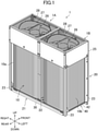
- the outdoor unit (1) includes a first unit (1A) located on the right side and a second unit (1B) located on the left side when viewed from the front surface side.
- the first unit (1A) and the second unit (1B) are integrated.
- the outdoor unit (1) includes a vertical rectangular-parallelepiped casing (20).
- the casing (20) houses therein components of a refrigerant circuit.
- the casing (20) includes a base member (21), a support (23), and a fan module (25) which are combined with one another.
- the base member (21) defines a bottom part of the casing (20).
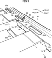
- the base member (21) includes a rectangular bottom plate (22), long installation legs (30) that each are fixed to a front edge portion or a rear edge portion of the bottom plate (22) and support the bottom plate (22) from below, and side stays (40) that each are fixed to a left edge portion or a right edge portion of the bottom plate (22).
- the support (23) includes four supports (23) provided at four corners of the base member (21) and extending in the up-down direction. The details of the base member (21) will be described later.
- the fan module (25) defines an upper part of the casing (20).
- the fan module (25) is located above the supports (23).
- the fan module (25) is a group in which a substantially rectangular-parallelepiped box having openings in an upper surface, a lower surface, and a front surface thereof houses a pair of left and right fans (26) and a pair of left and right bell mouths (27).
- the fan module (25) includes blow-out grills (28) at the opening in the upper surface.
- the fan module (25) houses the fans (26) each having a center axis of rotation extending in the up-down direction to blow out the air upward.
- a fan motor is provided below each of the fans (26). When the fans (26) are rotated, the air is sucked into the casing (20) from the outside of the casing (20) through a heat exchanger (10). The sucked air is blown out upward from the fan module (25) by the fans (26).
- the front surface of the casing (20) is covered with a front-surface panel (not illustrated).
- the front-surface panel is provided to extend from the installation legs (30) to an upper end of the fan module (25).
- the outdoor unit (1) is provided with components including component devices of a refrigerant circuit including a compressor (3), the heat exchanger (10), an outdoor expansion valve (not illustrated), an accumulator (4), and an oil separator (5); and control devices (such as an electric-component box (6)) housing electronic components for controlling the refrigerant circuit.
- Each of the indoor units is provided with devices, such as an indoor expansion valve and an indoor heat exchanger.
- the heat exchanger (10) is provided in the casing (20).
- the heat exchanger (10) includes a first heat exchanger (10a) provided in the first unit (1A), and a second heat exchanger (10b) provided in the second unit (1B).
- Each heat exchanger (10) includes three-surface plate-shaped heat exchange portions (11) and bent portions (12) between the respective heat exchange portions (11), and has a U-like shape in plan view.
- the heat exchanger (10) is a heat exchanger in which end portions of a plurality of flat tubes arranged in parallel with one another and extending in the horizontal direction are connected to a header collective tube. Multiple fins are attached to each flat tube at a small pitch.
- Each heat exchanger (10) is a multiple-row heat exchanger in which the flat tubes are arrayed in two rows.
- the base member (21) includes the bottom plate (22), the installation legs (30), and the side stays (40).
- the bottom plate (22) is formed of a corrugated plate-shaped member in which mountain portions (22a) and valley portions (22b) are alternately formed in the left-right direction of the outdoor unit (1).
- each of the valley portions (22b) is a portion having a substantially flat surface and located at the lowermost position of the bottom plate (22). At least one of the valley portions (22b) has a drainage hole (22c) at a position near the heat exchanger (10). Accordingly, while the water flowing from the heat exchanger (10) most likely remains in the valley portion (22b), the water can be drained through the drainage hole (22c).
- Each of the mountain portions (22a) is a portion protruding upward from the corresponding valley portion (22b).
- the mountain portion (22a) includes a portion that defines an inclined surface extending upward from the valley portion (22b), and a portion that defines a substantially flat surface continuing from the portion that defines the inclined surface and located above the valley portion (22b).
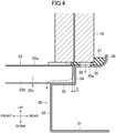
- Each of the installation legs (30) includes a fixed portion (31) that is fixed to an installation surface, a vertical portion (32) that extends upward from an end portion on one side in the front-rear direction of the fixed portion (31), a support portion (33) that supports from below an end portion of the bottom plate (22) on a side on which the mountain portion (22a) and the valley portion (22b) are viewed (in this case, the front-rear direction), a wall portion (34) that is located on the outer side of one of a front end portion and a rear end portion of the bottom plate (22) and that extends upward from the support portion (33), a mount portion (35) that extends outward from an upper end of the wall portion (34) and on which the heat exchanger (10) is mounted, and an end edge portion (36) that extends upward from an end edge on the outer side of the mount portion (35).
- the valley portion (22b) of the bottom plate (22) is mounted on the support portion (33).
- a predetermined gap (C) is provided between an end edge of the bottom plate (22) mounted on the support portion (33) and an end edge on the inner side of the mount portion (35) of the installation leg (30).
- the gap (C) defines a drainage channel for causing water adhering to the mountain portion (22a) of the bottom plate (22) to flow to the support portion (33).
- the support portion (33) is in contact with the valley portion (22b) of the bottom plate (22) and supports the installation leg (30) from below.
- a space is formed between the support portion (33) and the mountain portion (22a) of the bottom plate (22).
- the space communicates with the gap (C).
- the gap (C) functions as a drainage channel.
- the water guided to the support portion (33) through the gap (C) flows to a position below the bottom plate (22) through the space between the mountain portion (22a) of the bottom plate (22) and the support portion (33). Thus, the water unlikely flows to the outer side of the casing (20).
- the mount portion (35) of the installation leg (30) has a plurality of drainage holes (35a) that extend through the mount portion (35) in the up-down direction and that are spaced apart in the left-right direction.
- An upper surface of the mount portion (35) of the installation leg (30) is substantially flush with an upper surface of the mountain portion (22a) of the bottom plate (22) mounted on the support portion (33).
- An elastic member (37) is arranged to extend from the mountain portion (22a) of the bottom plate (22) to the mount portion (35) of the installation leg (30).
- the elastic member (37) is made of, for example, a rubber material, and has a shape from which a portion corresponding to the valley portion (22b) of the bottom plate (22) in plan view is cut and removed.
- the elastic member (37) has a through hole (38) formed at a position corresponding to the mount portion (35).
- the heat exchanger (10) is arranged to extend from the mountain portion (22a) of the bottom plate (22) to the mount portion (35) of the installation leg (30) via the elastic member (37).
- the heat exchanger (10) is frosted during heating operation.
- defrosting operation is performed to defrost the heat exchanger (10
- the water generated due to defrosting flows and runs down from the heat exchanger (10). Since the heat exchanger (10) is mounted on the mount portion (35) of the installation leg (30), the heat of the heat exchanger (10) is transferred to the installation leg (30) and heats the installation leg (30). Accordingly, the water flowing from the heat exchanger (10) to the installation leg (30) is not frozen.
- the flow of water is indicated by imaginary arrow lines.
- the water flowing from the heat exchanger (10) is drained to the outside of the casing (20) from the drainage hole (35a) formed in the mount portion (35) of the installation leg (30), the drainage hole (22c) formed in the valley portion (22b) of the bottom plate (22), and the drainage channel communicating with the gap (C) and defined by the wall portion (34) of the installation leg (30), the support portion (33), and the mountain portion (22a) of the bottom plate (22).
- Each of the side stays (40) is disposed to bridge between the pair of installation legs (30) at one of both end portions in the left-right direction.
- Each of the side stays (40) includes a mount portion (41) that defines a bottom surface of the casing (20) and on which the heat exchanger (10) is mounted, and an outer wall portion (42) that extends upward along an outer edge of the mount portion (41).
- the side stay (40) has both end portions in the front-rear direction coupled to the supports (23).
- the heat exchange portion (11) on the right side of the first heat exchanger (10a) is mounted on the mount portion (41) of the side stay (40) on the right side via an elastic member (43).
- the mount portion (41) of the side stay (40) on the right side has a plurality of long drainage holes (45) that extend in the front-rear direction and that are arranged in the front-rear direction.
- the heat exchange portion (11) on the left side of the second heat exchanger (10b) is mounted on the mount portion (41) of the side stay (40) on the left side.
- the mount portion (41) of the side stay (40) on the left side has a plurality of long drainage holes (45) that extend in the front-rear direction and that are arranged in the front-rear direction.
- the water flowing from the heat exchanger (10) is drained from the drainage holes (45) formed in the mount portion (41) of the side stay (40).
- An outdoor unit (1) for an air conditioner according to the present invention is provided with a heat exchanger (10) in a casing (20).
- the outdoor unit (1) includes a bottom plate (22) that defines a bottom surface of the casing (20); and an installation leg (30) that supports the bottom plate (22) from below.
- a portion of the heat exchanger (10) is mounted on the installation leg (30).
- the portion of the heat exchanger (10) is mounted on the installation leg (30) that supports the bottom plate (22) from below. Accordingly, the heat of the heat exchanger (10) is transferred to the installation leg (30) and heats the installation leg (30). Water flowing to the installation leg (30) from the heat exchanger (10) is not frozen, thereby increasing drainage performance.
- the installation leg (30) has a hole (35a) that extends through the installation leg (30) in an up-down direction.
- the installation leg (30) since the installation leg (30) has the drainage hole (35a), the water flowing from the heat exchanger (10) to the installation leg (30) can be drained from the drainage hole (35a).
- a mount surface of the installation leg (30) for the heat exchanger (10) is substantially flush with an upper surface of the bottom plate (22), a predetermined gap (C) is provided between an end edge of the bottom plate (22) and an end edge of the mount surface of the installation leg (30), and the heat exchanger (10) is mounted to extend from the bottom plate (22) to the installation leg (30) .
- the mount surface of the installation leg (30) for the heat exchanger (10) is substantially flush with the upper surface of the bottom plate (22).
- the heat exchanger (10) is mounted to extend from the bottom plate (22) to the installation leg (30).
- the gap is provided between the end edge of the bottom plate (22) and the end edge of the mount surface of the installation leg (30), the water flowing from the heat exchanger (10) can be drained from the gap.
- the bottom plate (22) is constituted of a corrugated plate-shaped member in which a mountain portion (22a) and a valley portion (22b) are formed to be arranged in a left-right direction; and the installation leg (30) includes a support portion (33) that supports from below an end portion of the bottom plate (22) on a side on which the mountain portion (22a) and the valley portion (22b) are viewed, a wall portion (34) that is located on an outer side of the end portion of the bottom plate (22) and that extends upward from the support portion (33), and a mount portion (35) that extends outward from an upper end of the wall portion (34) and on which the heat exchanger (10) is mounted.
- the installation leg (30) includes the support portion (33), the wall portion (34), and the mount portion (35).
- the support portion (33) supports from below the end portion of the bottom plate (22) on the side on which the mountain portion (22a) and the valley portion (22b) are viewed.
- the wall portion (34) is located on the outer side of the end portion of the bottom plate (22). Accordingly, the water flowing from the heat exchanger (10) mounted on the mount portion (35) can be drained from a drainage channel that is defined by the wall portion (34), the support portion (33), and the mountain portion (22a) of the bottom plate (22).
- the outdoor unit (1) in which the first unit (1A) and the second unit (1B) disposed on the left and right sides are integrated has been described; however, the outdoor unit (1) according to the present disclosure may be constituted of only one unit. That is, in the above-described embodiment, the outdoor unit (1) is provided with the two heat exchangers (10a, 10b); however, the outdoor unit (1) may be constituted of only one heat exchanger (10). In such a case, the number and size of at least one heat exchanger may be determined in accordance with the desirable performance of the heat exchanger.
- the present disclosure is useful for an outdoor unit for an air conditioner.
Landscapes
- Engineering & Computer Science (AREA)
- Chemical & Material Sciences (AREA)
- Combustion & Propulsion (AREA)
- Mechanical Engineering (AREA)
- General Engineering & Computer Science (AREA)
- Other Air-Conditioning Systems (AREA)
Claims (3)
- Außeneinheit für eine Klimaanlage, bereitgestellt mit einem Wärmetauscher (10) in einem Gehäuse (20), wobei die Außeneinheit Folgendes umfasst:eine Unterteilplatte (22), die eine untere Oberfläche des Gehäuses (20) definiert, wobei die Unterteilplatte (22) aus einem gewellten plattenförmigen Element besteht, in dem ein Bergabschnitt (22a) und ein Talabschnitt (22b) so ausgebildet sind, dass sie in einer Vorne-Hinten-Richtung oder einer Links-Rechts-Richtung eingerichtet sind;einen Installationsschenkel (30), der die Unterteilplatte (22) von unten stützt, wobei der Installationsschenkel (30) einen Stützabschnitt (33) einschließt, der einen Endabschnitt der Unterteilplatte (22) auf einer Seite, auf der der Bergabschnitt (22a) und der Talabschnitt (22b) betrachtet werden, von unten stützt,dadurch gekennzeichnet, dassein Abschnitt des Wärmetauschers (10) auf dem Installationsschenkel (30) befestigt ist,wobei der Installationsschenkel (30) weiter einen Wandabschnitt (34) einschließt, der sich an einer Außenseite des Endabschnitts der Unterteilplatte (22) befindet und sich von dem Stützabschnitt (33) nach oben erstreckt, und einen Befestigungsbereich (35), der sich von einem oberen Ende des Wandabschnitts (34) nach außen erstreckt und auf dem der Abschnitt des Wärmetauschers (10) montiert ist.
- Außeneinheit für die Klimaanlage nach Anspruch 1,
wobei der Befestigungsbereich (35) des Installationsschenkels (30) eine Öffnung (35a) aufweist, die sich durch den Befestigungsbereich (35) des Installationsschenkels (30) in einer Auf-Ab-Richtung erstreckt. - Außeneinheit für die Klimaanlage nach Anspruch 1 oder 2,wobei eine Befestigungsoberfläche des Installationsschenkels (30) für den Abschnitt des Wärmetauschers (10) im Wesentlichen bündig mit einer oberen Oberfläche der Unterteilplatte (22) ist,wobei ein vorbestimmter Spalt (C) zwischen einer Endkante der Unterteilplatte (22) und einer Endkante der Befestigungsoberfläche des Installationsschenkels (30) bereitgestellt ist, undwobei der Wärmetauscher (10) so befestigt ist, dass er sich von der Unterteilplatte (22) bis zu dem Installationsschenkel (30) erstreckt.
Applications Claiming Priority (2)
| Application Number | Priority Date | Filing Date | Title |
|---|---|---|---|
| JP2018015458A JP6673375B2 (ja) | 2018-01-31 | 2018-01-31 | 空気調和装置の室外機 |
| PCT/JP2018/043128 WO2019150720A1 (ja) | 2018-01-31 | 2018-11-22 | 空気調和装置の室外機 |
Publications (3)
| Publication Number | Publication Date |
|---|---|
| EP3730851A1 EP3730851A1 (de) | 2020-10-28 |
| EP3730851A4 EP3730851A4 (de) | 2021-02-24 |
| EP3730851B1 true EP3730851B1 (de) | 2022-03-02 |
Family
ID=67478073
Family Applications (1)
| Application Number | Title | Priority Date | Filing Date |
|---|---|---|---|
| EP18903934.0A Active EP3730851B1 (de) | 2018-01-31 | 2018-11-22 | Ausseneinheit für klimaanlage |
Country Status (7)
| Country | Link |
|---|---|
| US (1) | US11118796B2 (de) |
| EP (1) | EP3730851B1 (de) |
| JP (1) | JP6673375B2 (de) |
| CN (1) | CN111670326B (de) |
| AU (1) | AU2018407003B2 (de) |
| ES (1) | ES2909179T3 (de) |
| WO (1) | WO2019150720A1 (de) |
Families Citing this family (2)
| Publication number | Priority date | Publication date | Assignee | Title |
|---|---|---|---|---|
| KR102857859B1 (ko) | 2020-08-10 | 2025-09-10 | 삼성전자주식회사 | 공기조화기의 실외기 |
| JP7809201B2 (ja) * | 2022-04-25 | 2026-01-30 | 三菱電機株式会社 | 熱交換器支え装置 |
Family Cites Families (31)
| Publication number | Priority date | Publication date | Assignee | Title |
|---|---|---|---|---|
| JPS58111863U (ja) * | 1982-01-25 | 1983-07-30 | 三菱電機株式会社 | 空気調和機 |
| US4748827A (en) * | 1987-06-29 | 1988-06-07 | Chang Dick Y K | Coil support structure |
| JP5226744B2 (ja) * | 2001-09-28 | 2013-07-03 | 帝人株式会社 | 複合多孔膜の製造法 |
| US6705105B2 (en) * | 2002-05-24 | 2004-03-16 | American Standard International Inc. | Base pan and cabinet for an air conditioner |
| JP3719233B2 (ja) * | 2002-07-04 | 2005-11-24 | ダイキン工業株式会社 | 空気調和装置の室外ユニット |
| JP3722109B2 (ja) * | 2002-07-05 | 2005-11-30 | ダイキン工業株式会社 | 空気調和装置の室外ユニット |
| CA2414462C (en) * | 2002-12-17 | 2010-01-26 | Spinnaker Industries Inc. | Apparatus for screening |
| CN1548850A (zh) * | 2003-05-20 | 2004-11-24 | 乐金电子(天津)电器有限公司 | 空调室外机凝结水排水装置 |
| KR100988572B1 (ko) * | 2003-08-14 | 2010-10-18 | 삼성전자주식회사 | 공기조화기의 실외기 |
| US7418827B2 (en) * | 2006-01-20 | 2008-09-02 | Carrier Corporation | Vertical condensate pan with non-modifying slope attachment to horizontal pan for multi-poise furnace coils |
| KR101371886B1 (ko) * | 2007-10-31 | 2014-03-10 | 엘지전자 주식회사 | 공기조화기 |
| EP2354683A3 (de) * | 2010-01-28 | 2013-04-17 | Sanyo Electric Co., Ltd. | Außenraumeinheit für Klimaanlage |
| JP5420441B2 (ja) * | 2010-01-29 | 2014-02-19 | 三洋電機株式会社 | 空気調和装置の室外ユニット |
| JP5218628B2 (ja) * | 2011-11-30 | 2013-06-26 | ダイキン工業株式会社 | 空気調和装置の室外機 |
| JP5310829B2 (ja) * | 2011-11-30 | 2013-10-09 | ダイキン工業株式会社 | 空気調和装置における室外機のケーシング |
| JP5218629B2 (ja) * | 2011-12-12 | 2013-06-26 | ダイキン工業株式会社 | ヒータ及びそれを備えた冷凍装置の室外ユニット |
| JP5573980B2 (ja) * | 2012-01-24 | 2014-08-20 | ダイキン工業株式会社 | 結着剤、正極合剤及び負極合剤 |
| JP6028462B2 (ja) * | 2012-08-24 | 2016-11-16 | ダイキン工業株式会社 | 冷凍装置の室外機 |
| JPWO2014065258A1 (ja) * | 2012-10-22 | 2016-09-08 | ダイキン工業株式会社 | セパレータ及び二次電池 |
| JP2014115005A (ja) * | 2012-12-07 | 2014-06-26 | Daikin Ind Ltd | 空気調和装置 |
| JP6277523B2 (ja) * | 2014-08-08 | 2018-02-14 | パナソニックIpマネジメント株式会社 | 空気調和装置用室外機の底部構造 |
| CN105423452B (zh) * | 2014-09-12 | 2019-01-22 | Lg电子株式会社 | 空气调节器的室外机 |
| KR20160031230A (ko) * | 2014-09-12 | 2016-03-22 | 엘지전자 주식회사 | 공기 조화기의 실외기 |
| US10208968B2 (en) | 2014-12-26 | 2019-02-19 | Mitsubishi Electric Corporation | Outdoor unit |
| KR102283537B1 (ko) * | 2015-01-05 | 2021-07-29 | 엘지전자 주식회사 | 공기 조화기의 실외기 및 그 제조 방법 |
| JP6625379B2 (ja) * | 2015-09-10 | 2019-12-25 | 日立ジョンソンコントロールズ空調株式会社 | 冷凍空調装置 |
| JP6288147B2 (ja) * | 2016-04-06 | 2018-03-07 | ダイキン工業株式会社 | 熱源ユニット |
| JP6269717B2 (ja) * | 2016-04-21 | 2018-01-31 | ダイキン工業株式会社 | 熱源ユニット |
| JP6361685B2 (ja) * | 2016-04-21 | 2018-07-25 | ダイキン工業株式会社 | 熱源ユニット |
| JP6702341B2 (ja) * | 2018-01-31 | 2020-06-03 | ダイキン工業株式会社 | 空気調和装置の室外機 |
| JP6936160B2 (ja) * | 2018-01-31 | 2021-09-15 | ダイキン工業株式会社 | 空気調和装置の室外機 |
-
2018
- 2018-01-31 JP JP2018015458A patent/JP6673375B2/ja active Active
- 2018-11-22 AU AU2018407003A patent/AU2018407003B2/en active Active
- 2018-11-22 WO PCT/JP2018/043128 patent/WO2019150720A1/ja not_active Ceased
- 2018-11-22 ES ES18903934T patent/ES2909179T3/es active Active
- 2018-11-22 CN CN201880088210.7A patent/CN111670326B/zh active Active
- 2018-11-22 EP EP18903934.0A patent/EP3730851B1/de active Active
-
2020
- 2020-07-29 US US16/941,923 patent/US11118796B2/en active Active
Also Published As
| Publication number | Publication date |
|---|---|
| AU2018407003B2 (en) | 2020-08-13 |
| CN111670326A (zh) | 2020-09-15 |
| EP3730851A4 (de) | 2021-02-24 |
| WO2019150720A1 (ja) | 2019-08-08 |
| JP2019132543A (ja) | 2019-08-08 |
| US11118796B2 (en) | 2021-09-14 |
| US20200355376A1 (en) | 2020-11-12 |
| ES2909179T3 (es) | 2022-05-05 |
| JP6673375B2 (ja) | 2020-03-25 |
| EP3730851A1 (de) | 2020-10-28 |
| AU2018407003A1 (en) | 2020-07-30 |
| CN111670326B (zh) | 2021-06-01 |
Similar Documents
| Publication | Publication Date | Title |
|---|---|---|
| KR100988572B1 (ko) | 공기조화기의 실외기 | |
| EP2733435B1 (de) | Außenraumeinheit für Klimaanlage | |
| AU2008321997B2 (en) | Indoor unit for air conditioner | |
| EP2040008A2 (de) | Außeneinheit für eine Klimaanlage | |
| JP5464207B2 (ja) | 冷凍装置の室外ユニット | |
| EP2063192A1 (de) | Außenraumeinheit für Klimaanlage mit luftgekühltem Elektronikkasten und Wärmerohr | |
| EP2180267A2 (de) | Außenraumeinheit für Klimaanlage | |
| EP3009755B1 (de) | Ausseneinheit für klimaanlage und herstellungsverfahren für ausseneinheit für klimaanlage | |
| KR20100046388A (ko) | 공기조화기의 실외기 | |
| KR20110139834A (ko) | 공기조화기의 실내기 | |
| JP5398283B2 (ja) | 空調室外機 | |
| EP3730851B1 (de) | Ausseneinheit für klimaanlage | |
| CN102141275B (zh) | 空气调节装置的室外单元 | |
| JP2019132544A (ja) | 空気調和装置の室外機 | |
| JP5772590B2 (ja) | 冷凍装置の室外ユニット | |
| CN101178222A (zh) | 窗式空调器的隔板排水孔结构 | |
| JP7653622B2 (ja) | 室外機 | |
| CN101523123B (zh) | 空调装置 | |
| CN220669894U (zh) | 冰箱 | |
| JP2013130329A (ja) | 空気調和装置の室外ユニット | |
| WO2014199514A1 (ja) | 空気調和機の室外機、及び空気調和機の室外機の製造方法 | |
| KR20060117832A (ko) | 공기조화기의 드레인팬 | |
| JP6628931B2 (ja) | 空気調和装置の室外機 | |
| JP2008304184A (ja) | 空気調和装置 | |
| JP5232667B2 (ja) | 天井埋込型空気調和装置 |
Legal Events
| Date | Code | Title | Description |
|---|---|---|---|
| STAA | Information on the status of an ep patent application or granted ep patent |
Free format text: STATUS: THE INTERNATIONAL PUBLICATION HAS BEEN MADE |
|
| PUAI | Public reference made under article 153(3) epc to a published international application that has entered the european phase |
Free format text: ORIGINAL CODE: 0009012 |
|
| STAA | Information on the status of an ep patent application or granted ep patent |
Free format text: STATUS: REQUEST FOR EXAMINATION WAS MADE |
|
| 17P | Request for examination filed |
Effective date: 20200722 |
|
| AK | Designated contracting states |
Kind code of ref document: A1 Designated state(s): AL AT BE BG CH CY CZ DE DK EE ES FI FR GB GR HR HU IE IS IT LI LT LU LV MC MK MT NL NO PL PT RO RS SE SI SK SM TR |
|
| AX | Request for extension of the european patent |
Extension state: BA ME |
|
| A4 | Supplementary search report drawn up and despatched |
Effective date: 20210126 |
|
| RIC1 | Information provided on ipc code assigned before grant |
Ipc: F24F 1/36 20110101ALI20210120BHEP Ipc: F24F 1/16 20110101AFI20210120BHEP Ipc: F24F 13/22 20060101ALI20210120BHEP |
|
| DAV | Request for validation of the european patent (deleted) | ||
| DAX | Request for extension of the european patent (deleted) | ||
| REG | Reference to a national code |
Ref country code: DE Ref legal event code: R079 Ref document number: 602018031813 Country of ref document: DE Free format text: PREVIOUS MAIN CLASS: F24F0001560000 Ipc: F24F0001160000 |
|
| GRAP | Despatch of communication of intention to grant a patent |
Free format text: ORIGINAL CODE: EPIDOSNIGR1 |
|
| STAA | Information on the status of an ep patent application or granted ep patent |
Free format text: STATUS: GRANT OF PATENT IS INTENDED |
|
| GRAJ | Information related to disapproval of communication of intention to grant by the applicant or resumption of examination proceedings by the epo deleted |
Free format text: ORIGINAL CODE: EPIDOSDIGR1 |
|
| RIC1 | Information provided on ipc code assigned before grant |
Ipc: F24F 1/56 20110101ALI20211007BHEP Ipc: F24F 1/36 20110101ALI20211007BHEP Ipc: F24F 1/16 20110101AFI20211007BHEP |
|
| GRAP | Despatch of communication of intention to grant a patent |
Free format text: ORIGINAL CODE: EPIDOSNIGR1 |
|
| INTG | Intention to grant announced |
Effective date: 20211025 |
|
| INTG | Intention to grant announced |
Effective date: 20211112 |
|
| INTG | Intention to grant announced |
Effective date: 20211115 |
|
| GRAS | Grant fee paid |
Free format text: ORIGINAL CODE: EPIDOSNIGR3 |
|
| GRAA | (expected) grant |
Free format text: ORIGINAL CODE: 0009210 |
|
| STAA | Information on the status of an ep patent application or granted ep patent |
Free format text: STATUS: THE PATENT HAS BEEN GRANTED |
|
| AK | Designated contracting states |
Kind code of ref document: B1 Designated state(s): AL AT BE BG CH CY CZ DE DK EE ES FI FR GB GR HR HU IE IS IT LI LT LU LV MC MK MT NL NO PL PT RO RS SE SI SK SM TR |
|
| REG | Reference to a national code |
Ref country code: GB Ref legal event code: FG4D |
|
| REG | Reference to a national code |
Ref country code: CH Ref legal event code: EP Ref country code: AT Ref legal event code: REF Ref document number: 1472542 Country of ref document: AT Kind code of ref document: T Effective date: 20220315 |
|
| REG | Reference to a national code |
Ref country code: DE Ref legal event code: R096 Ref document number: 602018031813 Country of ref document: DE |
|
| REG | Reference to a national code |
Ref country code: IE Ref legal event code: FG4D |
|
| REG | Reference to a national code |
Ref country code: ES Ref legal event code: FG2A Ref document number: 2909179 Country of ref document: ES Kind code of ref document: T3 Effective date: 20220505 |
|
| REG | Reference to a national code |
Ref country code: LT Ref legal event code: MG9D |
|
| REG | Reference to a national code |
Ref country code: NL Ref legal event code: MP Effective date: 20220302 |
|
| PG25 | Lapsed in a contracting state [announced via postgrant information from national office to epo] |
Ref country code: SE Free format text: LAPSE BECAUSE OF FAILURE TO SUBMIT A TRANSLATION OF THE DESCRIPTION OR TO PAY THE FEE WITHIN THE PRESCRIBED TIME-LIMIT Effective date: 20220302 Ref country code: RS Free format text: LAPSE BECAUSE OF FAILURE TO SUBMIT A TRANSLATION OF THE DESCRIPTION OR TO PAY THE FEE WITHIN THE PRESCRIBED TIME-LIMIT Effective date: 20220302 Ref country code: NO Free format text: LAPSE BECAUSE OF FAILURE TO SUBMIT A TRANSLATION OF THE DESCRIPTION OR TO PAY THE FEE WITHIN THE PRESCRIBED TIME-LIMIT Effective date: 20220602 Ref country code: LT Free format text: LAPSE BECAUSE OF FAILURE TO SUBMIT A TRANSLATION OF THE DESCRIPTION OR TO PAY THE FEE WITHIN THE PRESCRIBED TIME-LIMIT Effective date: 20220302 Ref country code: HR Free format text: LAPSE BECAUSE OF FAILURE TO SUBMIT A TRANSLATION OF THE DESCRIPTION OR TO PAY THE FEE WITHIN THE PRESCRIBED TIME-LIMIT Effective date: 20220302 Ref country code: BG Free format text: LAPSE BECAUSE OF FAILURE TO SUBMIT A TRANSLATION OF THE DESCRIPTION OR TO PAY THE FEE WITHIN THE PRESCRIBED TIME-LIMIT Effective date: 20220602 |
|
| REG | Reference to a national code |
Ref country code: AT Ref legal event code: MK05 Ref document number: 1472542 Country of ref document: AT Kind code of ref document: T Effective date: 20220302 |
|
| PG25 | Lapsed in a contracting state [announced via postgrant information from national office to epo] |
Ref country code: PL Free format text: LAPSE BECAUSE OF FAILURE TO SUBMIT A TRANSLATION OF THE DESCRIPTION OR TO PAY THE FEE WITHIN THE PRESCRIBED TIME-LIMIT Effective date: 20220302 Ref country code: LV Free format text: LAPSE BECAUSE OF FAILURE TO SUBMIT A TRANSLATION OF THE DESCRIPTION OR TO PAY THE FEE WITHIN THE PRESCRIBED TIME-LIMIT Effective date: 20220302 Ref country code: GR Free format text: LAPSE BECAUSE OF FAILURE TO SUBMIT A TRANSLATION OF THE DESCRIPTION OR TO PAY THE FEE WITHIN THE PRESCRIBED TIME-LIMIT Effective date: 20220603 Ref country code: FI Free format text: LAPSE BECAUSE OF FAILURE TO SUBMIT A TRANSLATION OF THE DESCRIPTION OR TO PAY THE FEE WITHIN THE PRESCRIBED TIME-LIMIT Effective date: 20220302 |
|
| PG25 | Lapsed in a contracting state [announced via postgrant information from national office to epo] |
Ref country code: NL Free format text: LAPSE BECAUSE OF FAILURE TO SUBMIT A TRANSLATION OF THE DESCRIPTION OR TO PAY THE FEE WITHIN THE PRESCRIBED TIME-LIMIT Effective date: 20220302 |
|
| PG25 | Lapsed in a contracting state [announced via postgrant information from national office to epo] |
Ref country code: SM Free format text: LAPSE BECAUSE OF FAILURE TO SUBMIT A TRANSLATION OF THE DESCRIPTION OR TO PAY THE FEE WITHIN THE PRESCRIBED TIME-LIMIT Effective date: 20220302 Ref country code: SK Free format text: LAPSE BECAUSE OF FAILURE TO SUBMIT A TRANSLATION OF THE DESCRIPTION OR TO PAY THE FEE WITHIN THE PRESCRIBED TIME-LIMIT Effective date: 20220302 Ref country code: RO Free format text: LAPSE BECAUSE OF FAILURE TO SUBMIT A TRANSLATION OF THE DESCRIPTION OR TO PAY THE FEE WITHIN THE PRESCRIBED TIME-LIMIT Effective date: 20220302 Ref country code: PT Free format text: LAPSE BECAUSE OF FAILURE TO SUBMIT A TRANSLATION OF THE DESCRIPTION OR TO PAY THE FEE WITHIN THE PRESCRIBED TIME-LIMIT Effective date: 20220704 Ref country code: EE Free format text: LAPSE BECAUSE OF FAILURE TO SUBMIT A TRANSLATION OF THE DESCRIPTION OR TO PAY THE FEE WITHIN THE PRESCRIBED TIME-LIMIT Effective date: 20220302 Ref country code: CZ Free format text: LAPSE BECAUSE OF FAILURE TO SUBMIT A TRANSLATION OF THE DESCRIPTION OR TO PAY THE FEE WITHIN THE PRESCRIBED TIME-LIMIT Effective date: 20220302 Ref country code: AT Free format text: LAPSE BECAUSE OF FAILURE TO SUBMIT A TRANSLATION OF THE DESCRIPTION OR TO PAY THE FEE WITHIN THE PRESCRIBED TIME-LIMIT Effective date: 20220302 |
|
| PG25 | Lapsed in a contracting state [announced via postgrant information from national office to epo] |
Ref country code: IS Free format text: LAPSE BECAUSE OF FAILURE TO SUBMIT A TRANSLATION OF THE DESCRIPTION OR TO PAY THE FEE WITHIN THE PRESCRIBED TIME-LIMIT Effective date: 20220702 Ref country code: AL Free format text: LAPSE BECAUSE OF FAILURE TO SUBMIT A TRANSLATION OF THE DESCRIPTION OR TO PAY THE FEE WITHIN THE PRESCRIBED TIME-LIMIT Effective date: 20220302 |
|
| REG | Reference to a national code |
Ref country code: DE Ref legal event code: R097 Ref document number: 602018031813 Country of ref document: DE |
|
| PLBE | No opposition filed within time limit |
Free format text: ORIGINAL CODE: 0009261 |
|
| STAA | Information on the status of an ep patent application or granted ep patent |
Free format text: STATUS: NO OPPOSITION FILED WITHIN TIME LIMIT |
|
| PG25 | Lapsed in a contracting state [announced via postgrant information from national office to epo] |
Ref country code: DK Free format text: LAPSE BECAUSE OF FAILURE TO SUBMIT A TRANSLATION OF THE DESCRIPTION OR TO PAY THE FEE WITHIN THE PRESCRIBED TIME-LIMIT Effective date: 20220302 |
|
| 26N | No opposition filed |
Effective date: 20221205 |
|
| PG25 | Lapsed in a contracting state [announced via postgrant information from national office to epo] |
Ref country code: SI Free format text: LAPSE BECAUSE OF FAILURE TO SUBMIT A TRANSLATION OF THE DESCRIPTION OR TO PAY THE FEE WITHIN THE PRESCRIBED TIME-LIMIT Effective date: 20220302 |
|
| PG25 | Lapsed in a contracting state [announced via postgrant information from national office to epo] |
Ref country code: MC Free format text: LAPSE BECAUSE OF FAILURE TO SUBMIT A TRANSLATION OF THE DESCRIPTION OR TO PAY THE FEE WITHIN THE PRESCRIBED TIME-LIMIT Effective date: 20220302 |
|
| REG | Reference to a national code |
Ref country code: CH Ref legal event code: PL |
|
| P01 | Opt-out of the competence of the unified patent court (upc) registered |
Effective date: 20230525 |
|
| REG | Reference to a national code |
Ref country code: BE Ref legal event code: MM Effective date: 20221130 |
|
| PG25 | Lapsed in a contracting state [announced via postgrant information from national office to epo] |
Ref country code: LI Free format text: LAPSE BECAUSE OF NON-PAYMENT OF DUE FEES Effective date: 20221130 Ref country code: CH Free format text: LAPSE BECAUSE OF NON-PAYMENT OF DUE FEES Effective date: 20221130 |
|
| PG25 | Lapsed in a contracting state [announced via postgrant information from national office to epo] |
Ref country code: LU Free format text: LAPSE BECAUSE OF NON-PAYMENT OF DUE FEES Effective date: 20221122 |
|
| PG25 | Lapsed in a contracting state [announced via postgrant information from national office to epo] |
Ref country code: IE Free format text: LAPSE BECAUSE OF NON-PAYMENT OF DUE FEES Effective date: 20221122 |
|
| PG25 | Lapsed in a contracting state [announced via postgrant information from national office to epo] |
Ref country code: BE Free format text: LAPSE BECAUSE OF NON-PAYMENT OF DUE FEES Effective date: 20221130 |
|
| PG25 | Lapsed in a contracting state [announced via postgrant information from national office to epo] |
Ref country code: CY Free format text: LAPSE BECAUSE OF FAILURE TO SUBMIT A TRANSLATION OF THE DESCRIPTION OR TO PAY THE FEE WITHIN THE PRESCRIBED TIME-LIMIT Effective date: 20220302 |
|
| PG25 | Lapsed in a contracting state [announced via postgrant information from national office to epo] |
Ref country code: MK Free format text: LAPSE BECAUSE OF FAILURE TO SUBMIT A TRANSLATION OF THE DESCRIPTION OR TO PAY THE FEE WITHIN THE PRESCRIBED TIME-LIMIT Effective date: 20220302 Ref country code: HU Free format text: LAPSE BECAUSE OF FAILURE TO SUBMIT A TRANSLATION OF THE DESCRIPTION OR TO PAY THE FEE WITHIN THE PRESCRIBED TIME-LIMIT; INVALID AB INITIO Effective date: 20181122 |
|
| PG25 | Lapsed in a contracting state [announced via postgrant information from national office to epo] |
Ref country code: TR Free format text: LAPSE BECAUSE OF FAILURE TO SUBMIT A TRANSLATION OF THE DESCRIPTION OR TO PAY THE FEE WITHIN THE PRESCRIBED TIME-LIMIT Effective date: 20220302 |
|
| PG25 | Lapsed in a contracting state [announced via postgrant information from national office to epo] |
Ref country code: MT Free format text: LAPSE BECAUSE OF FAILURE TO SUBMIT A TRANSLATION OF THE DESCRIPTION OR TO PAY THE FEE WITHIN THE PRESCRIBED TIME-LIMIT Effective date: 20220302 |
|
| PGFP | Annual fee paid to national office [announced via postgrant information from national office to epo] |
Ref country code: FR Payment date: 20250930 Year of fee payment: 8 |
|
| PGFP | Annual fee paid to national office [announced via postgrant information from national office to epo] |
Ref country code: DE Payment date: 20250930 Year of fee payment: 8 |
|
| PGFP | Annual fee paid to national office [announced via postgrant information from national office to epo] |
Ref country code: GB Payment date: 20251001 Year of fee payment: 8 |
|
| PGFP | Annual fee paid to national office [announced via postgrant information from national office to epo] |
Ref country code: IT Payment date: 20251022 Year of fee payment: 8 |
|
| PGFP | Annual fee paid to national office [announced via postgrant information from national office to epo] |
Ref country code: ES Payment date: 20251209 Year of fee payment: 8 |