EP3731255B1 - Energiefilter und vorrichtung für geladene teilchenstrahlen - Google Patents
Energiefilter und vorrichtung für geladene teilchenstrahlen Download PDFInfo
- Publication number
- EP3731255B1 EP3731255B1 EP20164677.5A EP20164677A EP3731255B1 EP 3731255 B1 EP3731255 B1 EP 3731255B1 EP 20164677 A EP20164677 A EP 20164677A EP 3731255 B1 EP3731255 B1 EP 3731255B1
- Authority
- EP
- European Patent Office
- Prior art keywords
- plane
- sector magnet
- energy
- image
- focusing
- Prior art date
- Legal status (The legal status is an assumption and is not a legal conclusion. Google has not performed a legal analysis and makes no representation as to the accuracy of the status listed.)
- Active
Links
Images







Classifications
-
- H—ELECTRICITY
- H01—ELECTRIC ELEMENTS
- H01J—ELECTRIC DISCHARGE TUBES OR DISCHARGE LAMPS
- H01J37/00—Discharge tubes with provision for introducing objects or material to be exposed to the discharge, e.g. for the purpose of examination or processing thereof
- H01J37/02—Details
- H01J37/04—Arrangements of electrodes and associated parts for generating or controlling the discharge, e.g. electron-optical arrangement or ion-optical arrangement
- H01J37/05—Electron or ion-optical arrangements for separating electrons or ions according to their energy or mass
-
- H—ELECTRICITY
- H01—ELECTRIC ELEMENTS
- H01J—ELECTRIC DISCHARGE TUBES OR DISCHARGE LAMPS
- H01J37/00—Discharge tubes with provision for introducing objects or material to be exposed to the discharge, e.g. for the purpose of examination or processing thereof
- H01J37/26—Electron or ion microscopes; Electron or ion diffraction tubes
- H01J37/28—Electron or ion microscopes; Electron or ion diffraction tubes with scanning beams
-
- H—ELECTRICITY
- H01—ELECTRIC ELEMENTS
- H01J—ELECTRIC DISCHARGE TUBES OR DISCHARGE LAMPS
- H01J37/00—Discharge tubes with provision for introducing objects or material to be exposed to the discharge, e.g. for the purpose of examination or processing thereof
- H01J37/26—Electron or ion microscopes; Electron or ion diffraction tubes
- H01J37/295—Electron or ion diffraction tubes
-
- H—ELECTRICITY
- H01—ELECTRIC ELEMENTS
- H01J—ELECTRIC DISCHARGE TUBES OR DISCHARGE LAMPS
- H01J49/00—Particle spectrometers or separator tubes
- H01J49/44—Energy spectrometers, e.g. alpha-, beta-spectrometers
- H01J49/46—Static spectrometers
-
- H—ELECTRICITY
- H01—ELECTRIC ELEMENTS
- H01J—ELECTRIC DISCHARGE TUBES OR DISCHARGE LAMPS
- H01J2237/00—Discharge tubes exposing object to beam, e.g. for analysis treatment, etching, imaging
- H01J2237/05—Arrangements for energy or mass analysis
- H01J2237/055—Arrangements for energy or mass analysis magnetic
-
- H—ELECTRICITY
- H01—ELECTRIC ELEMENTS
- H01J—ELECTRIC DISCHARGE TUBES OR DISCHARGE LAMPS
- H01J2237/00—Discharge tubes exposing object to beam, e.g. for analysis treatment, etching, imaging
- H01J2237/05—Arrangements for energy or mass analysis
- H01J2237/057—Energy or mass filtering
-
- H—ELECTRICITY
- H01—ELECTRIC ELEMENTS
- H01J—ELECTRIC DISCHARGE TUBES OR DISCHARGE LAMPS
- H01J2237/00—Discharge tubes exposing object to beam, e.g. for analysis treatment, etching, imaging
- H01J2237/244—Detection characterized by the detecting means
- H01J2237/24485—Energy spectrometers
-
- H—ELECTRICITY
- H01—ELECTRIC ELEMENTS
- H01J—ELECTRIC DISCHARGE TUBES OR DISCHARGE LAMPS
- H01J2237/00—Discharge tubes exposing object to beam, e.g. for analysis treatment, etching, imaging
- H01J2237/26—Electron or ion microscopes
- H01J2237/28—Scanning microscopes
- H01J2237/2802—Transmission microscopes
Definitions
- the present invention relates to an energy filter and a charged particle beam apparatus.
- Electron energy loss spectroscopy is an analytical technique of irradiating a sample with an electron beam, and acquiring a spectrum that represents the loss energy level of electrons transmitted through the sample.
- the energy that an electron loses within the sample depends on the elements constituting the sample and on how atoms are mutually bonded. Therefore by examining the spectrum, it is possible to know the types of elements contained in the sample, and how the elements are bonded.
- TEM transmission electron microscopy
- an energy spectrum can be acquired by focusing the energy dispersive plane of the energy filter on a screen.
- TEM-EELS a technique of combining the transmission electron microscopy and an energy filter
- STEM-EELS a technique of combining scanning transmission electron microscopy (STEM) and an energy filter
- atomic resolution can be acquired more easily than in the transmission electron microscopy. Therefore in recent years, an elemental distribution observing method having atomic resolution using the scanning transmission electron microscopy has attracted attention.
- a TEM image can be acquired by focusing an achromatic plane of the energy filter on the screen. Furthermore, a TEM image, corresponding to a certain loss energy level of electrons, can be acquired by placing an energy selecting slot on the energy dispersive plane, and selecting only the electrons having a certain loss energy level. In addition, a distribution image of an element can be acquired by selecting the loss energy level intrinsic to the element. This technique is referred to as the energy filtering TEM (EF-TEM).
- EF-TEM energy filtering TEM
- Energy filters are classified into an in-column type and a post-column type.
- an energy filter is disposed between the intermediate lens and the projection lens of a transmission electron microscope.
- an energy filter is disposed behind the projection lens (e.g. under a lens barrel).
- An advantage of the in-column type is that it is not necessary to correct some of the aberrations that are generated from the energy filter itself, since these aberrations are cancelled out by the structural symmetry of the energy filter. Another advantage is that an image observation mode and a spectrum observation mode can easily be switched by the projection lens. A further advantage is that observation in a wide field of view, from low magnification to high magnification, can be supported because filtering is performed by the energy filter prior to magnification by the projection lens.
- a disadvantage of the in-column type is that the height of the apparatus (lens barrel) is increased because the energy filter is disposed between the intermediate lens and the projection lens, and this may lead to a deterioration of earthquake resistance and a drop in apparatus performance due to vibrations. Another disadvantage is that it is not easy to post-install the filter in a general purpose transmission electron microscope in an attempt to expand functionality.
- An advantage of the post-column type is that it can be easily post-installed into a general purpose transmission electron microscope, and at this time, it is not necessary to change the height of the apparatus.
- a disadvantage of the post-column type is that many component parts are needed to correct aberrations, and adjusting the axis is not easy. Further, cost is increased, and it is unsuitable for low-magnification observation because of the optical restrictions imposed when the energy filter is connected to a transmission electron microscope.
- JP-A-2001-243910 discloses a 180° inversion type aberration correcting ⁇ filter, in which an increase in the height of the apparatus is controlled by setting the sum of the deflection angles of the electron beams, which are deflected by the energy filter, to 180°.
- in-column energy filters such as ⁇ types, ⁇ types and mandolin types are known, in addition to the ⁇ types. Furthermore, ⁇ type filters are classified into an A-type and B-type according to the optical system.
- JP-A-2018-129171 discloses an in-column type energy filter which has a simple structure and can implement low aberration.
- the optical system of the energy filter includes an entrance crossover plane S1, an entrance image plane A1, an exit crossover plane (energy dispersive plane) S2, and an exit image plane (achromatic plane) A2.
- the optical system of the energy filter is characterized by these four important planes.
- a crossover is focused on the entrance crossover plane S1, and an image is focused on the entrance image plane A1.
- a plane where energy dispersion occurs is formed at a position to be mirror-symmetrical with the entrance crossover plane S1, and a plane where energy dispersion does not occur (achromatic plane A2) is formed at a position to be mirror-symmetrical with the entrance image plane A1.
- the energy resolution of an ⁇ filter is 1 ⁇ m/eV, for example, for an electron beam with an acceleration voltage of 200 kV.
- FIG. 21 illustrates the relationship between the achromatic plane A of the energy filter and the energy dispersive plane S.
- the entrance crossover plane S1 and the energy dispersive plane S2 are mirror-symmetrical with respect to a symmetry plane, and are optically equivalent.
- the entrance image plane A1 and the achromatic plane A2 are mirror-symmetrical with respect to a symmetry plane, and are optically equivalent. Therefore the entrance crossover plane S1 and the energy dispersive plane S2 are referred to as "energy dispersive plan S", unless a distinction is necessary.
- the entrance image plane A1 and the achromatic plane A2 are referred to as achromatic plane A, unless a distinction is necessary.
- the aberration coefficient of the ⁇ filter is determined by determining the shape and arrangement of the magnets of the ⁇ filter with respect to a given distance L.
- the correlation of the shapes of the magnets, their arrangement and the aberration coefficient is complicated (the degree of complexity is in proportion to the number of magnets), and in many cases, the above mentioned advantages are cancelled out or a disproportionate increase in the aberration coefficients occurs.
- the apparatus is designed so that the aberrations on the image plane are small, the aberrations on the energy dispersive plane normally tend to deteriorate. The opposite is also true.
- FIG. 22 is a diagram for describing geometric aberrations that are generated on the energy dispersive plane.
- An aberration of the energy spectrum that is generated on the energy dispersive plane becomes triangular, as illustrated in FIG. 22 , and increases in proportion to the square of the visual field size (angle of view ⁇ and ⁇ from one points on the energy dispersive plane to the image plane).
- the size of this shape becomes an index of the level of the energy resolution.
- the size of ⁇ is about 5 mrad, and the size of ⁇ is about 0.1 mrad.
- ⁇ is small, and the beam shape on the energy dispersive plane is handled as a point.
- the above mentioned aberration correcting omega filter can cancel out these remaining aberrations.
- the structure of the aberration correcting ⁇ filter is complicated.
- an energy filter has a simple structure, and can improve the energy resolution.
- an energy filter comprising:
- a charged particle beam apparatus including the above energy filter.
- This charged particle beam apparatus which includes the energy filter, can correct the geometric aberrations of the energy spectrum. Therefore this charged particle beam apparatus can improve the energy resolution with a simple configuration.
- an electron microscope for observing a sample by irradiating an electron beam is taken as an example of the charged particle beam apparatus according to the invention, but the charged particle beam apparatus according to the invention may be any apparatus for observing a sample by irradiating a charged particle beam (e.g. ions) other than an electron beam.
- a charged particle beam e.g. ions
- Examples of the charged particle beam apparatus according to the invention include a transmission electron microscope (TEM), and a scanning transmission electron microscope (STEM).
- FIG. 1 is a diagram illustrating a configuration of an electron microscope 1 equipped with the energy filter 100 according to the first embodiment.
- the electron microscope 1 is a transmission electron microscope.
- the electron microscope 1 includes an electron source 2, an illumination lens 3, an objective lens 4, an intermediate lens 5, the energy filter 100, a projection lens 6, and an imaging apparatus 7.
- the electron source 2 generates electrons.
- the electron source 2 is an electron gun in which electrons emitted from a cathode are accelerated by an anode such that an electron beam is emitted from the gun.
- the illumination lens 3 focuses the electron beam emitted from the electron source 2 onto a sample 9.
- the illumination lens 3 is constituted of a plurality of electron lenses, for example.
- the objective lens 4 is a lens in an initial stage of forming a transmission electron microscope (TEM) image using the electron beam transmitted through the sample 9.
- the objective lens 4 has pole pieces for applying a strong magnetic field to the sample 9, and which the sample 9 is placed between the pole pieces.
- the transmission electron microscope (TEM) image includes a "sample image” and a "diffraction pattern of the sample". If the TEM image is a sample image, the crossover is a diffraction pattern of the sample. And if the TEM image is a diffraction pattern of a sample, the crossover is a sample image.
- the TEM image is used in the following description based on the above definition.
- the intermediate lens 5 is constituted of four stages of lenses, and is disposed between the objective lens 4 and the energy filter 100. By the four-stage intermediate lens 5, magnification, image rotation, image focus and crossover focus can be adjusted.
- the four stage-intermediate lens 5 forms an image of (focuses) a crossover on the entrance crossover plane S1 of the energy filter 100, and forms an image on the entrance image plane A1 (performs focusing).
- the intermediate lens 5 focuses a diffraction pattern of the sample 9 on the entrance crossover plane S1 of the energy filter 100, and focuses an image of the sample 9 on the entrance image plane A1 of the energy filter 100. Further, in the case where a diffraction pattern of the sample 9 is observed with the electron microscope 1 (electron diffraction observation mode), the intermediate lens 5 focuses an image of the sample 9 on the entrance crossover plane S1 of the energy filter 100, and focuses a diffraction pattern of the sample 9 on the entrance image plane A1 of the energy filter 100.
- the energy filter 100 is disposed between the intermediate lens 5 and the projection lens 6.
- the energy filter 100 is an in-column energy filter (imaging energy filter).
- imaging energy filter imaging energy filter
- the trajectory of an electron passing through the energy filter 100 is a U-shape form. That is, the total deflection angle of the electron beam in the energy filter 100 is 180°.
- the optical system of the energy filter 100 includes the entrance crossover plane S1, the entrance image plane A1, the energy dispersive plane (exit crossover plane) S2, and the achromatic plane (exit image plane) A2.
- the crossover is focused on the entrance crossover plane S1 by the intermediate lens 5.
- the image is focused on the entrance image plane A1 by the intermediate lens 5.
- the energy filter 100 has a focusing function similar to an electron lens, and the entrance crossover plane S1 is projected onto the energy dispersive plane S2, and the entrance image plane A1 is projected onto the achromatic plane A2.
- the energy dispersive plane S2 is a plane on which the energy dispersion is generated.
- the crossover is focused on the energy dispersive plane S2.
- the energy dispersive plane S2 is disposed mirror-symmetrically with the entrance crossover plane S1 with respect to the symmetry plane M.
- No energy dispersion is generated on the achromatic plane A2.
- the image is formed on the achromatic plane A2.
- the achromatic plane A2 is disposed mirror-symmetrically with the entrance image plane A1 with respect to the symmetry plane M.
- An energy slit (not illustrated) is disposed in the energy dispersive plane S2. By selecting only electrons having a certain loss energy via the energy slit, a TEM image, corresponding to the loss energy, can be acquired (EF-TEM).
- the energy filter 100 includes a first sector magnet 10, a second sector magnet 20, an entrance aperture 30, and an aberration corrector 40.
- the second sector magnet 20 is disposed behind (on the downstream side in the flowing direction of the electron beam) the first sector magnet 10.
- the first sector magnet 10 and the second sector magnet 20 generate deflecting magnetic fields respectively for deflecting the electron beam.
- the first sector magnet 10 and the second sector magnet 20 constitute an optical system for focusing the crossover and the image.
- the first sector magnet 10 and the second sector magnet 20 are configured symmetrically with respect to the symmetry plane M. That is, the deflecting magnetic field generated by the first sector magnet 10 and the deflecting magnetic field generated by the second sector magnet 20 are symmetric with respect to the symmetry plane M.
- the first sector magnet 10 and the second sector magnet 20 are curved. As illustrated in FIG. 1 , the shape of the first sector magnet 10 is a sector of which center is the center O 10 , and of which central angle is 90°. Similarly, as illustrated in FIG. 1 , the shape of the second sector magnet 20 is a sector of which center is the center O 20 , and of which central angle is 90°.
- the traveling direction of the electron beam is rotated 90° by the first sector magnet 10.
- the traveling direction of the electron beam is rotated 90° by the second sector magnet 20. That is, the deflection angle of the electron beam in the first sector magnet 10 is 90°.
- the deflection angle of the electron beam in the second sector magnet 20 is 90°.
- the sum of the deflection angle of the electron beam in the first sector magnet 10 and the deflection angle of the electron beam in the second sector magnet 20 is 180°. Therefore the electron beam which entered the energy filter 100 is inverted 180°, and is emitted. That is, the central trajectory (optical axis) of the electron beam that enters the energy filter 100 and the central trajectory (optical axis) of the electron beam that is emitted from the energy filter 100 are parallel with each other.
- the polarity of the first sector magnet 10 and the polarity of the second sector magnet 20 are the same.
- Polarity here refers to the direction of the line of magnetic force of the deflecting magnetic field (direction of the magnetic field). That is, the direction of the line of magnetic force of the deflecting magnetic field generated by the first sector magnet 10 and the direction of the line of magnetic force of the deflecting magnetic field generated by the second sector magnet 20 are the same.
- the direction of the line of magnetic force (direction of magnetic field) of the second sector magnet 20 is the Y direction, and the direction of the line of magnetic force here is in the +Y direction.
- the direction of the line of magnetic force of the first sector magnet 10 is also in the +Y direction, because the polarity of the first sector magnet 10 and the polarity of the second sector magnet 20 are the same.
- an opposing pole piece surface 22 is an S pole
- an opposing pole piece surface 23 is an N pole.
- the entrance aperture 30 is used for limiting the field of view at the entrance of the energy filter 100.
- the entrance aperture 30 is disposed on the entrance side of the first sector magnet 10. That is, the entrance aperture 30 is disposed between the entrance crossover S1 and the first sector magnet 10. It is preferable that the position of the entrance aperture 30 is close to the entrance of the first sector magnet 10.
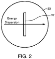
- FIG. 2 is a diagram schematically illustrating the entrance aperture 30.
- FIG. 2 is a view of the entrance aperture 30 along the optical axis.
- a slit 32 is formed in the entrance aperture 30.
- a longitudinal direction of the slit 32 is perpendicular to the energy dispersion direction.
- the ratio of the length in the longitudinal direction and the length in the lateral direction is 10:1, for example.
- the shape of the slit 32 is a rectangle having a longitudinal side which is perpendicular to the energy dispersion direction, for example.
- the entrance aperture 30 limits ⁇ to 0.5 mrad, and limits ⁇ to 5 mrad, for example.
- the aberration corrector 40 is disposed on the symmetry plane M, as illustrated in FIG 1 . That is, the aberration corrector 40 is disposed between the first sector magnet 10 and the second sector magnet 20.
- the aberration corrector 40 includes a hexapole disposed on the symmetry plane M, and a quadrupole disposed on the symmetry plane M. That is, the aberration corrector 40 can generate both a hexapole field and a quadrupole field on the symmetry plane M.
- the geometric aberration of the energy filter 100 is corrected, and energy resolution can be improved. The reason thereof will be described later.
- the projection lens 6 is constituted of three stages of lenses that are disposed behind the energy filter 100 (on the downstream side in the flowing direction of the electron beam).
- the plane that is focused on the imaging apparatus 7 can be switched by adjusting the excitation of the three-stage projection lens 6. Thereby both the energy loss image and the energy spectrum can be acquired.
- the achromatic plane A2 of the energy filter 100 is focused on the imaging apparatus 7 by the three-stage projection lens 6.
- the energy dispersive plane S2 of the energy filter 100 is focused on the imaging apparatus 7 by the three-stage projection lens 6.
- the projection lens 6 may be constituted of two stages of lenses.
- the imaging apparatus 7 captures an energy loss image, an energy spectrum, a TEM image or the like focused by the projection lens 6.
- the imaging apparatus 7 is a digital camera, such as a CCD camera or a CMOS camera, for example.
- the electron microscope 1 has two barrels, 8a and 8b.
- the lens barrel 8a accommodates the electron source 2, the illumination lens 3, the objective lens 4 and the intermediate lens 5.
- the lens barrel 8b accommodates the projection lens 6.
- the lens barrel 8a and the lens barrel 8b are disposed in parallel on a pedestal (not illustrated).
- the energy filter 100 is disposed in the portion connecting the two lens barrels, 8a and 8b.
- the electron beam emitted from the electron source 2 is focused by the illumination lens 3, and is irradiated onto the sample 9.
- the electron beam irradiated onto the sample 9 transmits through the sample 9, and is focused by the objective lens 4.
- the crossover is focused on the entrance crossover plane S1 by the intermediate lens 5, and the image is focused on the entrance image plane A1.
- the crossover focused on the entrance crossover plane S1 is projected onto the energy dispersive plane S2, and the image focused on the entrance image plane A1 is projected onto the achromatic plane A2.
- An energy loss image can be observed when the achromatic plane A2 is focused on the imaging apparatus 7 using the projection lens 6.
- an energy spectrum can be acquired when the energy dispersive plane S2 is focused on the imaging apparatus 7 using the projection lens 6.
- FIG. 3 is a diagram illustrating the trajectories of the electron beam in the energy filter 100.
- FIG. 4 is a diagram of a comparative example, illustrating the trajectories of an electron beam in an ⁇ filter (B-type). Although a center axis (optical axis) of the energy filter is curved, the axis is drawn as a straight line in FIG. 3 and FIG. 4 for convenience.
- FIG. 3 indicates four fundamental trajectories: x ⁇ , y ⁇ , x ⁇ and y ⁇ of the electron beam in the energy filter 100.
- the trajectory x ⁇ and the trajectory y ⁇ are trajectories passing through the center of the image plane.
- the trajectory x ⁇ and the trajectory y ⁇ are trajectories passing through the center of the crossover plane.
- xchi is a trajectory of the energy dispersed electron.
- the crossover focused on the entrance crossover plane S1 by the intermediate lens 5 is focused on the energy dispersive plane S2.
- the crossover focused on the entrance crossover plane S1 by the intermediate lens 5 is focused on the energy dispersive plane S2 in the same way as the trajectory x ⁇ .
- the crossover is focused in the X direction once, excluding the initial focusing on the entrance crossover plane S1, and the crossover is focused in the Y direction once, excluding the initial focusing on the entrance crossover plane S1. Further, the focusing position of the crossover in the X direction and the focusing position of the crossover in the Y direction are on the energy dispersive plane S2, excluding the initial entrance crossover plane S1.
- the image focused on the entrance image plane A1 by the intermediate lens 5 is focused on the symmetry plane M and on the achromatic plane A2.
- the image focused on the entrance image plane A1 by the intermediate lens 5 is focused on the symmetry plane M and on the achromatic plane A2.
- the image is focused in the X direction twice, excluding the initial focusing on the entrance image plane A1, and the image is focused in the Y direction twice, excluding the initial focusing on the entrance image plane A1.
- the focusing position of the image in the X direction and the focusing position of the image in the Y direction are on the symmetry plane M and on the achromatic plane A2, excluding the initial entrance image plane A1.
- the images focused on the entrance image plane A1 and the achromatic plane A2 are virtual images, and in the trajectories x ⁇ and y ⁇ , the focal positions are positions where the straight line extending the electron trajectory, indicated by the broken line, intersects with the optical axis.
- the crossover is focused in the X direction three times (see trajectory x ⁇ ).
- the focusing positions of the crossover in the X direction are the three intersections of the trajectory x ⁇ with the optical axis of the filter.
- the image is focused in the X direction twice (see trajectory x ⁇ ).
- the focusing positions of the image in the X direction are on the symmetry plane M and the achromatic plane A2.
- the number of times of focusing of the crossover in the Y direction and the number of times of focusing of the image in the Y direction are one less than in the X direction respectively (see trajectories y ⁇ and y ⁇ ).
- the number of times of focusing of the crossover in the Y direction and the number of times of focusing of the image in the Y direction are one less than in the X direction respectively. Therefore in the ⁇ filter (B-type), the image is inverted. Furthermore, in the ⁇ filter (B-type), the number of times of focusing in the Y direction is decreased, so that an increase in the angle of the end surface of the pole piece (end surface angle) required for focusing is controlled, and the resultant aberrations are controlled.
- the number of times of focusing is the same in the X direction and the Y direction, as mentioned above, therefore an inversion of the image is not generated, unlike in the ⁇ filter (B-type).
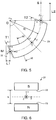
- the configuration of the second sector magnet 20 will be described next with reference to FIG. 5 to FIG. 7 . Since the first sector magnet 10 and the second sector magnet 20 are designed to be symmetric, the first sector magnet 10 has a similar configuration as the second sector magnet 20.
- FIG. 5 to FIG. 7 are diagrams schematically illustrating the second sector magnet 20 of the energy filter 100.
- FIG. 6 is a cross-sectional view of the second sector magnet 20 illustrated in FIG. 5 , taken along the VI-VI line.
- FIG. 7 illustrates a modification of the second sector magnet 20.
- FIG. 7 illustrates a state in which the opposing pole piece surfaces 22 and 23 of the second sector magnet 20 are tilted (tilt angle ⁇ ⁇ 0°).
- the X, Y and Z axes are indicated as three mutually orthogonal axes. It is assumed that the electrons travel in the Z direction, electrons are deflected by the deflecting magnetic field in the X direction, and the line of magnetic force in the deflecting magnetic field lies in the Y direction.
- the focus parameters are calculated when a distance L between the crossover plane S (energy dispersive plane S2) and the image plane (achromatic plane A2), or an equivalent distance L between the entrance crossover plane S1 and the entrance image plane A1 (see FIG. 1 ) is given. Since the energy filter 100 has a simple structure, there are no other focus parameters than these four parameters (distance L1, distance L2, end surface angle T1 and end surface angle T2). Therefore if the distance L is given, the distance L1, distance L2, end surface angle T1 and end surface angle T2 are determined uniquely.
- the tilt angle ⁇ of the opposing pole piece surfaces 22 and 23 may be used as another focus parameter, but this aspect is not considered here.
- the distance L1 is the distance between the symmetry plane M and the entrance of the second sector magnet 20.
- the distance L2 is the distance between the exit of the second sector magnet 20 and the crossover plane S (energy dispersive plane S2).
- the end surface angle T1 is the angle of the end surface of the second sector magnet 20 on the entrance side.
- the end surface angle T2 is the angle of the end surface of the second sector magnet 20 on the exit side.
- the end surface angle T1 and the end surface angle T2 are defined such that the X axis is at 0° and a counterclockwise direction is a positive direction.
- the use of the end surface angles T1 and T2 can provide a focusing action in the Y direction. However if the end surface angles T1 and T2 are too large, aberrations tend to increase.
- FIG. 8 is a graph plotting the focus parameters (distance L1, distance L2, end surface angle T1 and end surface angle T2) with respect to the given distance L.
- the deflection radius R is the radius of the central trajectory of the electron beam in the second sector magnet 20.
- the deflection angle ⁇ is the deflection angle of the electron beam in the second sector magnet 20.
- the range of the distance L, in which the crossover and the image can be focused in the X direction and the Y direction in the energy filter 100, as illustrated in FIG. 3 is 538 mm or more. That is, the distance L can be set within the range of L > 3.6 R (see Table 1).
- the distance L2 is in the range from 80 mm to 90 mm
- the end surface angle T1 is in the range from 24° to 26°
- the end surface angle T2 is in the range from -25° to -18°
- the distance L1 is longer than 0 mm and shorter than the distance L2.
- the focusing action can be produced in the Y direction. Therefore the end surface angles T1 and T2 can be reduced. As a consequence, the end surface angles T1 and T2 are not limited to the above ranges.
- the end surface angles T1 and T2 can be reduced to a minimum when the second sector magnet 20 produces the same focusing action at all times for both the X and Y directions, that is, when the round lens focus condition is met.
- the range of the distance L, in which focusing is possible, is not limited to the above mentioned range (see Table 1).
- the distance XC is the distance between the position at which a plane including the opposing pole piece surface 22 and a plane including the opposing pole piece surface 23 intersect, and the central trajectory of the electron beam in the second sector magnet 20.
- the distance s is the distance between the opposing pole piece surface 22 and the opposing pole piece surface 23 in the YZ plane.
- the focusing action in the X direction and the focusing action in the Y direction may be different in intermediate positions if both match on the final focal plane. This is referred to as stigmatic focus.
- the range of the distance L depends on the deflection angle ⁇ and the tilt angle ⁇ of the opposing pole piece surfaces 22 and 23.
- the minimum value of the distance L, at which the crossover and the image can be focused in the X direction and Y direction is given as indicated in the following Table 1.
- the deflection radius R 150 mm.
- the configuration of the second sector magnet 20 has been described above, but this content is also applicable to the first sector magnet 10, as mentioned above. That is, even in the first sector magnet 10, the distance L between the crossover plane S (entrance crossover plane S1) and the image plane A (entrance image plane A1) satisfies L > 3.6 R, for example.
- the distance L1 corresponds to the distance between the symmetry plane M and the exit of the first sector magnet 10.
- the distance L2 corresponds to the distance between the entrance of the first sector magnet 10 and the crossover plane S (entrance crossover plane S1).
- the end surface angle T1 corresponds to the angle of the end surface on the exit side of the first sector magnet 10.
- the end surface angle T2 corresponds to the angle of the end surface on the entrance side of the first sector magnet 10.
- a method of improving the energy resolution by disposing the entrance aperture to limit ⁇ and ⁇ is known.
- an aperture, in which a round hole is formed, is normally used.
- the energy resolution improves as the size of the hole is reduced, but as the size of the hole is reduced, the spectral intensity decreases and the sensitivity of the energy filter decreases.
- a real image is formed on the symmetry plane M of the energy filter and a hexapole is disposed at this position, for example.
- this method is impractical because a hexapole can correct the spectrum only in one direction, which is insufficient to correct the aberrations.
- the hexapole is disposed at a position other than the position of the symmetry plane M, a space, for mechanically disposing the hexapole, is required, therefore the design of the fundamental optical system is restricted.
- FIG. 9 is a graph of a reference example illustrating the shapes of a spectrum in the case of using an entrance aperture in which a round hole is formed.
- ⁇ ⁇ 5 mrad and ⁇ ⁇ 5 mrad are the shapes of a spectrum in the case of using an entrance aperture in which a round hole is formed.
- the two triangular beams in FIG. 9 indicate an energy dispersion of a beam of an electron without energy loss (no loss), and an energy dispersion of a beam of an electron which lost energy (5 eV loss).
- the elliptical beam shape inside the triangle indicates the geometric aberration of the energy dispersive plane generated by plotting ⁇ estimating the image plane in the 1 mrad to 5 mrad range.
- the abscissa in FIG. 9 corresponds to the X axis
- the ordinate in FIG. 9 corresponds to the Y axis.
- the unit of length is mm.
- the X direction is the energy dispersion direction.
- FIG. 10 is a graph illustrating the shapes of the spectrum in the case of using the entrance aperture 30 in which a rectangular slit 32 is formed.
- the beam size in the energy dispersion direction (X direction) in the case of using the entrance aperture 30 alone is not different from the case of using an entrance aperture having a round hole indicated in FIG. 9 . Therefore the energy resolution does not improve.
- FIG. 11 is a graph illustrating the shapes of a spectrum in the case of using the entrance aperture 30 in which the rectangular slit 32 is formed, and defocusing from the energy dispersive plane.
- the spectrum shapes becomes the shapes indicated in FIG. 11 .
- the total beam size in the energy dispersion direction does not change. That is, the energy resolution does not improve, even after defocusing.
- FIG. 12 is a graph illustrating the shapes of a spectrum in the case of using the entrance aperture 30 in which a rectangular slit is formed, defocusing from the energy dispersive plane, and using a hexapole.
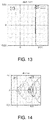
- FIG. 13 is a graph illustrating the shapes of a spectrum in the case of using the entrance aperture 30 in which a rectangular slit is formed, defocusing from the energy dispersive plane, and using a hexapole and quadrupole.
- the quadrupole disposed on the symmetry plane M the focusing on the energy dispersive plane is changed, thereby the energy resolution can be improved, as indicated in FIG. 13 .
- FIG. 14 is a graph illustrating the shapes of a spectrum in the case of using an entrance aperture in which a round hole is formed, and defocusing from the energy dispersive plane.
- FIG. 15 is a graph illustrating the shapes of a spectrum in the case of using the entrance aperture in which a round hole is formed, defocusing from the energy dispersive plane, and using an hexapole.
- FIG. 16 is a graph illustrating the shapes of a spectrum in the case of using the entrance aperture in which a round hole is formed, defocusing from the energy dispersive plane, and using the hexapole and quadrupole.
- the energy resolution cannot be improved if the entrance aperture, in which a round hole is formed, is used, compared with the case of using the entrance aperture 30.
- the geometric aberrations of the energy spectrum can be corrected by the entrance aperture 30 and the aberration corrector 40.
- the energy resolution can be improved.
- the energy filter 100 has the following features.
- the energy filter 100 is an energy filter that forms a real image on the symmetry plane M, and includes: the entrance aperture 30 provided with a slit having a longitudinal direction in a direction perpendicular to the energy dispersion direction, is formed; and an hexapole and a quadrupole disposed on the symmetry plane M. Therefore the energy filter 100 can correct the geometric aberrations of the energy spectrum with a simple structure, and can improve energy resolution. Furthermore, by disposing the hexapole and the quadrupole on the symmetry plane M where a real image is formed, the aberrations of the energy spectrum can be corrected without affecting the image.
- a number of times of focusing of the crossover in the X direction and in the Y direction are once respectively, excluding the initial focusing of the entrance crossover plane S1, and the image forming position of the crossover in the X direction and in the Y direction are on the energy dispersive plane S2, excluding the initial entrance crossover plane S1.
- a number of times of focusing of the image in the X direction and in the Y direction are twice respectively, excluding the initial focusing of the entrance image plane A1, and the focusing position of the image in the X direction and in the Y direction are on the symmetry plane M and the achromatic plane A2, excluding the initial entrance image plane A1. Therefore according to the energy filter 100, the structure can be simplified, and low aberration can be implemented.
- the first sector magnet 10 and the second sector magnet 20 are configured to be mirror-symmetric with respect to the symmetry plane M. Therefore in the energy filter 100, some aberrations (e.g. part of second-order geometric aberrations) can be cancelled out.
- the deflection angle ⁇ is 90°, and the tilt angle ⁇ is 0°
- the distance L between the energy dispersive plane S2 and the achromatic plane A2 satisfies L > 3.6 R.
- the distance L between the entrance crossover plane S1 and the entrance image plane A1 satisfies L > 3.6 R. That is, the sum of the deflection angle of the electron beam in the first sector magnet 10 and the deflection angle of the electron beam in the second sector magnet 20 is 180°, and the distance L satisfies L > 3.6 R. Therefore according to the energy filter 100, the structure can be simplified, and low aberration can be implemented.
- the deflection angle ⁇ is 45°, and the tilt angle ⁇ is 0°
- the distance L between the energy dispersive plane S2 and the achromatic plane A2 satisfies L > 3.2 R.
- the distance L between the entrance crossover plane S1 and the entrance image plane A1 satisfies L > 3.2 R. That is, the sum of the deflection angle of the electron beam in the first sector magnet 10 and the deflection angle of the electron beam in the second sector magnet 20 is 90°, and the distance L satisfies L > 3.2 R. Therefore according to the energy filter 100, the structure can be simplified, and low aberration can be implemented.
- the energy filter 100 the sum of the deflection angle of the electron beam in the first sector magnet 10 and the deflection angle of the electron beam in the second sector magnet 20 is 180°. Therefore as illustrated in FIG. 1 , the energy filter 100 can be disposed in a portion connecting the two lens barrels 8a and 8b in the electron microscope 1, and an increase in the height of the electron microscope (lens barrels) can be controlled.
- the electron microscope 1 can implement a low cost and high performance electron microscope since the energy filter 100, which can have a simple structure and implement low aberration, is included. Further, the axis adjustment of the electron microscope 1 easy, since the energy filter 100 has low aberration.
- the energy filter 100 is disposed between the intermediate lens 5 and the projection lens 6. Therefore in the electron microscope 1, some aberrations generated from the energy filter itself, due to the symmetric structure of the energy filter, can be cancelled out, hence these aberrations need not be corrected. Furthermore, in the electron microscope 1, the image observation mode and the spectrum observation mode can be easily switched by the projection lens 6. In addition, in the electron microscope 1, filtering is performed by the energy filter prior to magnification by the projection lens, therefore observation in a wide field of view, from low to high magnification, can be supported.
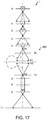
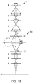
- FIG. 17 and FIG. 18 are diagrams illustrating an example of an energy filter 200 according to the second embodiment, and optical systems disposed in front and rear of the energy filter.
- FIG. 17 illustrates the state where the achromatic plane A2 is focused on the screen 11
- FIG. 18 illustrates the state where the energy dispersive plane S2 is focused on the screen 11.
- FIG. 17 and FIG. 18 only the imaging system of the electron microscope 1 is illustrated for convenience.
- the energy filter 200 according to the second embodiment is an A-type omega energy filter ( ⁇ filter).
- An intermediate lens 5 constituted of four stages is disposed between the energy filter 200 and the objective lens 4.
- the four-stage intermediate lens 5 is adjusted so as to form an image (focuses) of a crossover on the entrance crossover plane S1, and form an image on the entrance image plane A1 (performs focusing).
- a plane of which image is formed on the screen 11 is switched by adjusting the excitation of the three-stage projection lens 6, whereby an energy loss image and an energy spectrum can be acquired.
- the achromatic plane A2 is focused on the screen 11 by the three-stage projection lens 6, as illustrated in FIG. 17 .
- the energy dispersive plane S2 is focused on the screen 11 by the three-stage projection lens 6, as illustrated in FIG. 18 .
- An energy slit 12 is used to select only electrons having a certain loss energy. By selecting only electrons which have a certain loss energy using the energy slit 12, a TEM image corresponding to the loss energy can be acquired (EF-TEM).
- An entrance aperture 30 is used to limit the field of view that enters the energy filter 200. By using the entrance aperture 30 to control the field of view that enters the energy filter 200, a spectrum, which is less affected by aberrations, can be acquired.
- FIG. 19 is a diagram illustrating the configuration of the energy filter 200.
- the X, Y and Z axes are indicated as three mutually orthogonal axes. It is assumed that the electrons travel in the Z direction, electrons are deflected by the deflecting magnetic field in the X direction, and the line of magnetic force in the deflecting magnetic field lies in the Y direction.
- the energy filter 200 includes: a first sector magnet 210, a second sector magnet 220, a third sector magnet 230, a fourth sector magnet 240, an entrance aperture 30 and an aberration corrector 40.
- the first sector magnet 210, the second sector magnet 220, the third sector magnet 230 and the fourth sector magnet 240 are disposed in this order from the entrance side of the energy filter 200.
- the first sector magnet 210 and the fourth sector magnet 240 are disposed symmetrically with respect to the symmetry plane M.
- the second sector magnet 220 and the third sector magnet 230 are disposed symmetrically with respect to the symmetry plane M.
- the entrance aperture 30 is disposed between the first crossover plane S1 and the first sector magnet 210.
- a slit 32 having a longitudinal direction in a direction perpendicular to the energy dispersion direction (see FIG. 2 ), is disposed.
- the aberration corrector 40 is disposed on the symmetry plane M.
- the aberration corrector 40 is disposed between the second sector magnet 220 and the third sector magnet 230.
- the aberration corrector 40 includes a hexapole and a quadrupole.
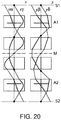
- FIG. 20 is a diagram illustrating trajectories of an electron beam in the energy filter 200.
- FIG. 20 four fundamental trajectories of the energy filter, x ⁇ , y ⁇ , x ⁇ and y ⁇ , are illustrated.
- the center axis (optical axis) of the energy filter is curved, the optical axis is drawn as a straight line for convenience in FIG. 20 .
- the sector magnet is indicated by a square region.
- the energy filter 200 is an A-type ⁇ filter.
- the x ⁇ ray intersects with the optical axis at three points, excluding the entrance crossover plane S1. That is, a number of times of focusing of the crossover in the X direction is three, excluding the initial focusing of the entrance crossover plane. A number of times of focusing of the crossover in the Y direction is the same as the number of times of focusing the crossover in the X direction.
- the x ⁇ ray intersects with the optical axis at two points (M and A2), excluding the entrance image plane A1. That is, a number of times of focusing of the image in the X direction is twice, excluding the initial focusing of the entrance image plane A1. A number of times of focusing of the image in the Y direction is the same as the number of times of focusing of the image in the X direction.
- the energy filter in the case where the trajectory of electrons is U-shaped was described, and in the second embodiment, the ⁇ filter in the case where the trajectory of electrons is an ⁇ type was described, but the invention can also be applied to other energy filters with which a real image is formed on the symmetry plane M.
- the sum of the deflection angles of the electron beams is 180° was described, but the sum of the deflection angles of the electron beams is not limited to this, and may be 90°, 135°, 210° or the like, for example.
Landscapes
- Chemical & Material Sciences (AREA)
- Analytical Chemistry (AREA)
- Electron Tubes For Measurement (AREA)
- Analysing Materials By The Use Of Radiation (AREA)
Claims (6)
- Energiefilter (100, 200), umfassend:eine Mehrzahl von Sektormagneten (10, 20; 210, 220, 230, 240), welche in Bezug auf eine Symmetrieebene (M), einen Hexapol und einen Quadrupol (40), welche an der Symmetrieebene angeordnet sind, symmetrisch eingerichtet sind, wobei der Energiefilter ein reales Bild an der Symmetrieebene bildet;dadurch gekennzeichnet, dass der Energiefilter ferner eine mit einem Schlitz (32) bereitgestellte Eingangsapertur (30) umfasst, welche in einer Richtung, welche senkrecht zu einer Energiedispersionsrichtung ist, eine longitudinale Richtung aufweist.
- Energiefilter nach Anspruch 1, ferner umfassend:einen ersten Sektormagneten und einen zweiten Sektormagneten, welche ein ablenkendes magnetisches Feld erzeugen, welches einen geladenen Teilchenstrahl ablenkt, wobeider erste Sektormagnet und der zweite Sektormagnet in Bezug auf die Symmetrieebene spiegelsymmetrisch eingerichtet sind,die Polarität des ersten Sektormagneten und die Polarität des zweiten Sektormagneten identisch sind,der erste Sektormagnet und der zweite Sektormagnet ein optisches System zum Fokussieren eines Crossovers und eines Bildes begründen, wenn sich der geladene Teilchenstrahl in einer Z-Richtung fortbewegt, der geladene Teilchenstrahl durch das ablenkende magnetische Feld in einer X-Richtung abgelenkt wird und eine Richtung einer magnetischen Kraftlinie in dem ablenkenden magnetischen Feld einer Y-Richtung entspricht, wobei die Anzahl von Malen eines Fokussierens des Crossovers in der X-Richtung und die Anzahl von Malen eines Fokussierens des Crossovers in der Y-Richtung bei beiden einmalig ist, mit Ausnahme eines initialen Fokussierens einer Eingangscrossoverebene,eine Fokussierposition des Crossovers in der X-Richtung und eine Fokussierposition des Crossovers in der Y-Richtung einer energiedispersiven Ebene entsprechen, mit Ausnahme einer initialen Eingangscrossoverebene,die Anzahl von Malen eines Fokussierens des Bildes in der X-Richtung und die Anzahl von Malen des Fokussierens des Bildes in der Y-Richtung zweimal ist, mit Ausnahme eines initialen Fokussierens an einer Eingangsbildebene,eine Fokussierposition des Bildes in der X-Richtung und eine Fokussierposition des Bildes in der Y-Richtung der Symmetrieebene und einer achromatischen Ebene entsprechen, mit Ausnahme einer initialen Eingangsbildebene,ein reales Bild an der Position der Symmetrieebene gebildet ist, wenn das Bild in der X-Richtung und in der Y-Richtung fokussiert ist,die Eingangscrossoverebene und die energiedispersive Ebene in Bezug auf die Symmetrieebene spiegelsymmetrisch positioniert sind, unddie Eingangsbildebene und die achromatische Ebene in Bezug auf die Symmetrieebene spiegelsymmetrisch positioniert sind.
- Energiefilter (100) nach Anspruch 2, wobei die Eingangsapertur (30) zwischen der initialen Eingangscrossoverebene (S1) und dem ersten Sektormagneten (10) angeordnet ist und der Hexapol und der Quadrupol (40) zwischen dem ersten Sektormagneten (10) und dem zweiten Sektormagneten (20) angeordnet sind.
- Energiefilter nach Anspruch 1, wobei der Energiefilter einem Omegatyp entspricht, wenn sich der geladene Teilchenstrahl in einer Z-Richtung fortbewegt,der geladene Teilchenstrahl durch das ablenkende magnetische Feld in einer X-Richtung abgelenkt wird und eine Richtung einer magnetischen Kraftlinie in einem ablenkenden magnetischen Feld einer Y-Richtung entspricht,die Anzahl von Malen eines Fokussierens eines Crossovers in der X-Richtung drei ist, mit Ausnahme eines initialen Fokussierens an einer Eingangscrossoverebene,die Anzahl von Malen eines Fokussierens eines Bildes in der X-Richtung zweimal ist, mit Ausnahme eines initialen Fokussierens an einer Eingangsbildebene,die Anzahl von Malen eines Fokussierens des Crossovers in der Y-Richtung der gleichen Anzahl von Malen eines Fokussierens des Crossovers in der X-Richtung entspricht und die Anzahl von Malen eines Fokussierens des Bildes in der Y-Richtung der gleichen Anzahl von Malen eines Fokussierens des Bildes in der X-Richtung entspricht.
- Energiefilter (200) nach Anspruch 4, ferner umfassend:einen ersten Sektormagneten (210), einen zweiten Sektormagneten (220), einen dritten Sektormagneten (230) und einen vierten Sektormagneten (240),wobei der erste Sektormagnet, der zweite Sektormagnet, der dritte Sektormagnet und der vierte Sektormagnet in dieser Reihenfolge von einer Eingangsseite aus angeordnet sind,der erste Sektormagnet und der vierte Sektormagnet in Bezug auf die Symmetrieebene (M) symmetrisch angeordnet sind,der zweite Sektormagnet und der dritte Sektormagnet in Bezug auf die Symmetrieebene symmetrisch angeordnet sind, wobeidie Eingangsapertur (30) zwischen einer initialen Eingangscrossoverebene (S1) und dem ersten Sektormagnet angeordnet ist,und der Hexapol und der Quadrupol (40) zwischen dem zweiten Sektormagneten und dem dritten Sektormagneten angeordnet sind.
- Vorrichtung für einen geladenen Teilchenstrahl, umfassend den Energiefilter nach einem der Ansprüche 1 bis 5.
Applications Claiming Priority (1)
| Application Number | Priority Date | Filing Date | Title |
|---|---|---|---|
| JP2019073666A JP6808772B2 (ja) | 2019-04-08 | 2019-04-08 | エネルギーフィルタおよび荷電粒子線装置 |
Publications (2)
| Publication Number | Publication Date |
|---|---|
| EP3731255A1 EP3731255A1 (de) | 2020-10-28 |
| EP3731255B1 true EP3731255B1 (de) | 2021-08-18 |
Family
ID=69953774
Family Applications (1)
| Application Number | Title | Priority Date | Filing Date |
|---|---|---|---|
| EP20164677.5A Active EP3731255B1 (de) | 2019-04-08 | 2020-03-20 | Energiefilter und vorrichtung für geladene teilchenstrahlen |
Country Status (3)
| Country | Link |
|---|---|
| US (1) | US11043353B2 (de) |
| EP (1) | EP3731255B1 (de) |
| JP (1) | JP6808772B2 (de) |
Families Citing this family (1)
| Publication number | Priority date | Publication date | Assignee | Title |
|---|---|---|---|---|
| US20250112018A1 (en) * | 2023-09-29 | 2025-04-03 | Fei Company | Aberration correction systems and charged particle microscope systems including the same |
Family Cites Families (12)
| Publication number | Priority date | Publication date | Assignee | Title |
|---|---|---|---|---|
| DE4041495A1 (de) * | 1990-12-22 | 1992-06-25 | Zeiss Carl Fa | Elektronenenergiefilter, vorzugsweise vom alpha- oder omega-typ |
| DE4310559A1 (de) * | 1993-03-26 | 1994-09-29 | Zeiss Carl Fa | Abbildendes Elektronenenergiefilter |
| DE69402283T2 (de) * | 1993-05-21 | 1997-09-18 | Philips Electronics Nv | Energiefilter mit Korrektur von chromatischen Aberrationen zweiter ordnung |
| JP3518271B2 (ja) * | 1997-08-28 | 2004-04-12 | 株式会社日立製作所 | エネルギーフィルタおよびこれを備えた電子顕微鏡 |
| DE19828741A1 (de) * | 1998-06-27 | 1999-12-30 | Leo Elektronenmikroskopie Gmbh | Elektronenmikroskop mit einem abbildenden magnetischen Energiefilter |
| DE10005347A1 (de) | 2000-02-08 | 2001-08-09 | Leo Elektronenmikroskopie Gmbh | Elektronenenergiefilter mit magnetischen Umlenkbereichen |
| DE10020382A1 (de) * | 2000-04-26 | 2001-10-31 | Ceos Gmbh | Strahlerzeugungssystem für Elektronen oder Ionenstrahlen hoher Monochromasie oder hoher Stromdichte |
| JP3942341B2 (ja) * | 2000-06-21 | 2007-07-11 | 日本電子株式会社 | 磁界型エネルギーフィルタ |
| JP4150568B2 (ja) * | 2002-10-03 | 2008-09-17 | 日本電子株式会社 | 電子顕微鏡 |
| JP2005183021A (ja) * | 2003-12-16 | 2005-07-07 | Jeol Ltd | エネルギーアナライザ |
| JP5934513B2 (ja) * | 2012-02-09 | 2016-06-15 | 日本電子株式会社 | 透過電子顕微鏡 |
| JP6914666B2 (ja) * | 2017-02-08 | 2021-08-04 | 日本電子株式会社 | エネルギーフィルタおよび荷電粒子線装置 |
-
2019
- 2019-04-08 JP JP2019073666A patent/JP6808772B2/ja active Active
-
2020
- 2020-03-20 EP EP20164677.5A patent/EP3731255B1/de active Active
- 2020-03-23 US US16/827,156 patent/US11043353B2/en active Active
Also Published As
| Publication number | Publication date |
|---|---|
| EP3731255A1 (de) | 2020-10-28 |
| JP2020173911A (ja) | 2020-10-22 |
| US20200321185A1 (en) | 2020-10-08 |
| JP6808772B2 (ja) | 2021-01-06 |
| US11043353B2 (en) | 2021-06-22 |
Similar Documents
| Publication | Publication Date | Title |
|---|---|---|
| US6924488B2 (en) | Charged-particle beam apparatus equipped with aberration corrector | |
| US6191423B1 (en) | Correction device for correcting the spherical aberration in particle-optical apparatus | |
| JP4368381B2 (ja) | 荷電粒子ビーム系用の荷電粒子ビームエネルギー幅低減系 | |
| US8178850B2 (en) | Chromatic aberration corrector for charged-particle beam system and correction method therefor | |
| EP2325863B1 (de) | Korrektor für axiale Aberrationen einer teilchenoptischen Linse | |
| KR101633978B1 (ko) | 모노크로메이터 및 이를 구비한 하전입자빔 장치 | |
| US20090014649A1 (en) | Electron beam apparatus | |
| EP1381073A1 (de) | Aberrations-korrigierter optischer Apparat für geladene Teilchen | |
| JPH11509972A (ja) | 粒子光学機器のレンズ収差補正用補正装置 | |
| US6960763B2 (en) | Energy filter and electron microscope | |
| US20180005797A1 (en) | Scanning electron microscope | |
| US7105833B2 (en) | Deflection system for a particle beam device | |
| JP4357530B2 (ja) | 荷電粒子ビーム系用の2段式荷電粒子ビームエネルギー幅低減系 | |
| US10546714B2 (en) | Energy filter and charged particle beam system | |
| US6608308B1 (en) | Electrostatic lens systems for secondary-electron mapping-projection apparatus, and mapping-projection apparatus and methods comprising same | |
| US11043353B2 (en) | Energy filter and charged particle beam apparatus | |
| US6307205B1 (en) | Omega energy filter | |
| JP4343951B2 (ja) | 荷電粒子ビーム系用の単段式荷電粒子ビームエネルギー幅低減系 | |
| US6441378B1 (en) | Magnetic energy filter | |
| US5955732A (en) | Omega-type energy filter | |
| EP4668313A2 (de) | Aberrationskorrektur in der spektroskopie geladener teilchen | |
| JP2007242490A (ja) | 荷電粒子線光学系用の収差補正光学装置及び光学系 |
Legal Events
| Date | Code | Title | Description |
|---|---|---|---|
| PUAI | Public reference made under article 153(3) epc to a published international application that has entered the european phase |
Free format text: ORIGINAL CODE: 0009012 |
|
| STAA | Information on the status of an ep patent application or granted ep patent |
Free format text: STATUS: THE APPLICATION HAS BEEN PUBLISHED |
|
| STAA | Information on the status of an ep patent application or granted ep patent |
Free format text: STATUS: REQUEST FOR EXAMINATION WAS MADE |
|
| AK | Designated contracting states |
Kind code of ref document: A1 Designated state(s): AL AT BE BG CH CY CZ DE DK EE ES FI FR GB GR HR HU IE IS IT LI LT LU LV MC MK MT NL NO PL PT RO RS SE SI SK SM TR |
|
| AX | Request for extension of the european patent |
Extension state: BA ME |
|
| 17P | Request for examination filed |
Effective date: 20201015 |
|
| RBV | Designated contracting states (corrected) |
Designated state(s): AL AT BE BG CH CY CZ DE DK EE ES FI FR GB GR HR HU IE IS IT LI LT LU LV MC MK MT NL NO PL PT RO RS SE SI SK SM TR |
|
| GRAP | Despatch of communication of intention to grant a patent |
Free format text: ORIGINAL CODE: EPIDOSNIGR1 |
|
| STAA | Information on the status of an ep patent application or granted ep patent |
Free format text: STATUS: GRANT OF PATENT IS INTENDED |
|
| INTG | Intention to grant announced |
Effective date: 20210419 |
|
| GRAS | Grant fee paid |
Free format text: ORIGINAL CODE: EPIDOSNIGR3 |
|
| GRAA | (expected) grant |
Free format text: ORIGINAL CODE: 0009210 |
|
| STAA | Information on the status of an ep patent application or granted ep patent |
Free format text: STATUS: THE PATENT HAS BEEN GRANTED |
|
| RAP3 | Party data changed (applicant data changed or rights of an application transferred) |
Owner name: JEOL LTD. |
|
| AK | Designated contracting states |
Kind code of ref document: B1 Designated state(s): AL AT BE BG CH CY CZ DE DK EE ES FI FR GB GR HR HU IE IS IT LI LT LU LV MC MK MT NL NO PL PT RO RS SE SI SK SM TR |
|
| REG | Reference to a national code |
Ref country code: GB Ref legal event code: FG4D |
|
| REG | Reference to a national code |
Ref country code: CH Ref legal event code: EP |
|
| REG | Reference to a national code |
Ref country code: DE Ref legal event code: R096 Ref document number: 602020000398 Country of ref document: DE |
|
| REG | Reference to a national code |
Ref country code: IE Ref legal event code: FG4D Ref country code: AT Ref legal event code: REF Ref document number: 1422385 Country of ref document: AT Kind code of ref document: T Effective date: 20210915 |
|
| REG | Reference to a national code |
Ref country code: LT Ref legal event code: MG9D |
|
| REG | Reference to a national code |
Ref country code: NL Ref legal event code: MP Effective date: 20210818 |
|
| REG | Reference to a national code |
Ref country code: AT Ref legal event code: MK05 Ref document number: 1422385 Country of ref document: AT Kind code of ref document: T Effective date: 20210818 |
|
| PG25 | Lapsed in a contracting state [announced via postgrant information from national office to epo] |
Ref country code: NO Free format text: LAPSE BECAUSE OF FAILURE TO SUBMIT A TRANSLATION OF THE DESCRIPTION OR TO PAY THE FEE WITHIN THE PRESCRIBED TIME-LIMIT Effective date: 20211118 Ref country code: PT Free format text: LAPSE BECAUSE OF FAILURE TO SUBMIT A TRANSLATION OF THE DESCRIPTION OR TO PAY THE FEE WITHIN THE PRESCRIBED TIME-LIMIT Effective date: 20211220 Ref country code: HR Free format text: LAPSE BECAUSE OF FAILURE TO SUBMIT A TRANSLATION OF THE DESCRIPTION OR TO PAY THE FEE WITHIN THE PRESCRIBED TIME-LIMIT Effective date: 20210818 Ref country code: FI Free format text: LAPSE BECAUSE OF FAILURE TO SUBMIT A TRANSLATION OF THE DESCRIPTION OR TO PAY THE FEE WITHIN THE PRESCRIBED TIME-LIMIT Effective date: 20210818 Ref country code: LT Free format text: LAPSE BECAUSE OF FAILURE TO SUBMIT A TRANSLATION OF THE DESCRIPTION OR TO PAY THE FEE WITHIN THE PRESCRIBED TIME-LIMIT Effective date: 20210818 Ref country code: AT Free format text: LAPSE BECAUSE OF FAILURE TO SUBMIT A TRANSLATION OF THE DESCRIPTION OR TO PAY THE FEE WITHIN THE PRESCRIBED TIME-LIMIT Effective date: 20210818 Ref country code: BG Free format text: LAPSE BECAUSE OF FAILURE TO SUBMIT A TRANSLATION OF THE DESCRIPTION OR TO PAY THE FEE WITHIN THE PRESCRIBED TIME-LIMIT Effective date: 20211118 Ref country code: RS Free format text: LAPSE BECAUSE OF FAILURE TO SUBMIT A TRANSLATION OF THE DESCRIPTION OR TO PAY THE FEE WITHIN THE PRESCRIBED TIME-LIMIT Effective date: 20210818 Ref country code: SE Free format text: LAPSE BECAUSE OF FAILURE TO SUBMIT A TRANSLATION OF THE DESCRIPTION OR TO PAY THE FEE WITHIN THE PRESCRIBED TIME-LIMIT Effective date: 20210818 Ref country code: ES Free format text: LAPSE BECAUSE OF FAILURE TO SUBMIT A TRANSLATION OF THE DESCRIPTION OR TO PAY THE FEE WITHIN THE PRESCRIBED TIME-LIMIT Effective date: 20210818 |
|
| PG25 | Lapsed in a contracting state [announced via postgrant information from national office to epo] |
Ref country code: PL Free format text: LAPSE BECAUSE OF FAILURE TO SUBMIT A TRANSLATION OF THE DESCRIPTION OR TO PAY THE FEE WITHIN THE PRESCRIBED TIME-LIMIT Effective date: 20210818 Ref country code: LV Free format text: LAPSE BECAUSE OF FAILURE TO SUBMIT A TRANSLATION OF THE DESCRIPTION OR TO PAY THE FEE WITHIN THE PRESCRIBED TIME-LIMIT Effective date: 20210818 Ref country code: GR Free format text: LAPSE BECAUSE OF FAILURE TO SUBMIT A TRANSLATION OF THE DESCRIPTION OR TO PAY THE FEE WITHIN THE PRESCRIBED TIME-LIMIT Effective date: 20211119 |
|
| PG25 | Lapsed in a contracting state [announced via postgrant information from national office to epo] |
Ref country code: NL Free format text: LAPSE BECAUSE OF FAILURE TO SUBMIT A TRANSLATION OF THE DESCRIPTION OR TO PAY THE FEE WITHIN THE PRESCRIBED TIME-LIMIT Effective date: 20210818 |
|
| PG25 | Lapsed in a contracting state [announced via postgrant information from national office to epo] |
Ref country code: DK Free format text: LAPSE BECAUSE OF FAILURE TO SUBMIT A TRANSLATION OF THE DESCRIPTION OR TO PAY THE FEE WITHIN THE PRESCRIBED TIME-LIMIT Effective date: 20210818 |
|
| REG | Reference to a national code |
Ref country code: DE Ref legal event code: R097 Ref document number: 602020000398 Country of ref document: DE |
|
| PG25 | Lapsed in a contracting state [announced via postgrant information from national office to epo] |
Ref country code: SM Free format text: LAPSE BECAUSE OF FAILURE TO SUBMIT A TRANSLATION OF THE DESCRIPTION OR TO PAY THE FEE WITHIN THE PRESCRIBED TIME-LIMIT Effective date: 20210818 Ref country code: SK Free format text: LAPSE BECAUSE OF FAILURE TO SUBMIT A TRANSLATION OF THE DESCRIPTION OR TO PAY THE FEE WITHIN THE PRESCRIBED TIME-LIMIT Effective date: 20210818 Ref country code: RO Free format text: LAPSE BECAUSE OF FAILURE TO SUBMIT A TRANSLATION OF THE DESCRIPTION OR TO PAY THE FEE WITHIN THE PRESCRIBED TIME-LIMIT Effective date: 20210818 Ref country code: EE Free format text: LAPSE BECAUSE OF FAILURE TO SUBMIT A TRANSLATION OF THE DESCRIPTION OR TO PAY THE FEE WITHIN THE PRESCRIBED TIME-LIMIT Effective date: 20210818 Ref country code: CZ Free format text: LAPSE BECAUSE OF FAILURE TO SUBMIT A TRANSLATION OF THE DESCRIPTION OR TO PAY THE FEE WITHIN THE PRESCRIBED TIME-LIMIT Effective date: 20210818 Ref country code: AL Free format text: LAPSE BECAUSE OF FAILURE TO SUBMIT A TRANSLATION OF THE DESCRIPTION OR TO PAY THE FEE WITHIN THE PRESCRIBED TIME-LIMIT Effective date: 20210818 |
|
| PLBE | No opposition filed within time limit |
Free format text: ORIGINAL CODE: 0009261 |
|
| STAA | Information on the status of an ep patent application or granted ep patent |
Free format text: STATUS: NO OPPOSITION FILED WITHIN TIME LIMIT |
|
| 26N | No opposition filed |
Effective date: 20220519 |
|
| PG25 | Lapsed in a contracting state [announced via postgrant information from national office to epo] |
Ref country code: IT Free format text: LAPSE BECAUSE OF FAILURE TO SUBMIT A TRANSLATION OF THE DESCRIPTION OR TO PAY THE FEE WITHIN THE PRESCRIBED TIME-LIMIT Effective date: 20210818 |
|
| PG25 | Lapsed in a contracting state [announced via postgrant information from national office to epo] |
Ref country code: MC Free format text: LAPSE BECAUSE OF FAILURE TO SUBMIT A TRANSLATION OF THE DESCRIPTION OR TO PAY THE FEE WITHIN THE PRESCRIBED TIME-LIMIT Effective date: 20210818 |
|
| REG | Reference to a national code |
Ref country code: BE Ref legal event code: MM Effective date: 20220331 |
|
| PG25 | Lapsed in a contracting state [announced via postgrant information from national office to epo] |
Ref country code: LU Free format text: LAPSE BECAUSE OF NON-PAYMENT OF DUE FEES Effective date: 20220320 Ref country code: IE Free format text: LAPSE BECAUSE OF NON-PAYMENT OF DUE FEES Effective date: 20220320 |
|
| PG25 | Lapsed in a contracting state [announced via postgrant information from national office to epo] |
Ref country code: BE Free format text: LAPSE BECAUSE OF NON-PAYMENT OF DUE FEES Effective date: 20220331 |
|
| REG | Reference to a national code |
Ref country code: CH Ref legal event code: PL |
|
| PG25 | Lapsed in a contracting state [announced via postgrant information from national office to epo] |
Ref country code: LI Free format text: LAPSE BECAUSE OF NON-PAYMENT OF DUE FEES Effective date: 20230331 Ref country code: CH Free format text: LAPSE BECAUSE OF NON-PAYMENT OF DUE FEES Effective date: 20230331 |
|
| PG25 | Lapsed in a contracting state [announced via postgrant information from national office to epo] |
Ref country code: MK Free format text: LAPSE BECAUSE OF FAILURE TO SUBMIT A TRANSLATION OF THE DESCRIPTION OR TO PAY THE FEE WITHIN THE PRESCRIBED TIME-LIMIT Effective date: 20210818 Ref country code: CY Free format text: LAPSE BECAUSE OF FAILURE TO SUBMIT A TRANSLATION OF THE DESCRIPTION OR TO PAY THE FEE WITHIN THE PRESCRIBED TIME-LIMIT Effective date: 20210818 |
|
| PG25 | Lapsed in a contracting state [announced via postgrant information from national office to epo] |
Ref country code: HU Free format text: LAPSE BECAUSE OF FAILURE TO SUBMIT A TRANSLATION OF THE DESCRIPTION OR TO PAY THE FEE WITHIN THE PRESCRIBED TIME-LIMIT; INVALID AB INITIO Effective date: 20200320 |
|
| PG25 | Lapsed in a contracting state [announced via postgrant information from national office to epo] |
Ref country code: TR Free format text: LAPSE BECAUSE OF FAILURE TO SUBMIT A TRANSLATION OF THE DESCRIPTION OR TO PAY THE FEE WITHIN THE PRESCRIBED TIME-LIMIT Effective date: 20210818 |
|
| PG25 | Lapsed in a contracting state [announced via postgrant information from national office to epo] |
Ref country code: MT Free format text: LAPSE BECAUSE OF FAILURE TO SUBMIT A TRANSLATION OF THE DESCRIPTION OR TO PAY THE FEE WITHIN THE PRESCRIBED TIME-LIMIT Effective date: 20210818 |
|
| PG25 | Lapsed in a contracting state [announced via postgrant information from national office to epo] |
Ref country code: SI Free format text: LAPSE BECAUSE OF FAILURE TO SUBMIT A TRANSLATION OF THE DESCRIPTION OR TO PAY THE FEE WITHIN THE PRESCRIBED TIME-LIMIT Effective date: 20210818 |
|
| PGFP | Annual fee paid to national office [announced via postgrant information from national office to epo] |
Ref country code: GB Payment date: 20260324 Year of fee payment: 7 |
|
| PGFP | Annual fee paid to national office [announced via postgrant information from national office to epo] |
Ref country code: DE Payment date: 20260319 Year of fee payment: 7 |
|
| PGFP | Annual fee paid to national office [announced via postgrant information from national office to epo] |
Ref country code: FR Payment date: 20260320 Year of fee payment: 7 |