EP3731370B1 - Procédé et système de génération d'une attribution entre un compteur de consommation et un dispositif de commande - Google Patents
Procédé et système de génération d'une attribution entre un compteur de consommation et un dispositif de commande Download PDFInfo
- Publication number
- EP3731370B1 EP3731370B1 EP20165067.8A EP20165067A EP3731370B1 EP 3731370 B1 EP3731370 B1 EP 3731370B1 EP 20165067 A EP20165067 A EP 20165067A EP 3731370 B1 EP3731370 B1 EP 3731370B1
- Authority
- EP
- European Patent Office
- Prior art keywords
- control device
- meter
- values
- subscriber
- control
- Prior art date
- Legal status (The legal status is an assumption and is not a legal conclusion. Google has not performed a legal analysis and makes no representation as to the accuracy of the status listed.)
- Active
Links
Images



Classifications
-
- H—ELECTRICITY
- H02—GENERATION; CONVERSION OR DISTRIBUTION OF ELECTRIC POWER
- H02J—ELECTRIC POWER NETWORKS; CIRCUIT ARRANGEMENTS OR SYSTEMS FOR SUPPLYING OR DISTRIBUTING ELECTRIC POWER; SYSTEMS FOR STORING ELECTRIC ENERGY
- H02J13/00—Circuit arrangements for providing remote monitoring or remote control of equipment in a power distribution network
- H02J13/13—Circuit arrangements for providing remote monitoring or remote control of equipment in a power distribution network characterised by the transmission of data to equipment in the power network
-
- G—PHYSICS
- G01—MEASURING; TESTING
- G01R—MEASURING ELECTRIC VARIABLES; MEASURING MAGNETIC VARIABLES
- G01R22/00—Arrangements for measuring time integral of electric power or current, e.g. electricity meters
- G01R22/06—Arrangements for measuring time integral of electric power or current, e.g. electricity meters by electronic methods
- G01R22/061—Details of electronic electricity meters
- G01R22/063—Details of electronic electricity meters related to remote communication
-
- H—ELECTRICITY
- H02—GENERATION; CONVERSION OR DISTRIBUTION OF ELECTRIC POWER
- H02J—ELECTRIC POWER NETWORKS; CIRCUIT ARRANGEMENTS OR SYSTEMS FOR SUPPLYING OR DISTRIBUTING ELECTRIC POWER; SYSTEMS FOR STORING ELECTRIC ENERGY
- H02J3/00—Circuit arrangements for AC mains or AC distribution networks
-
- Y—GENERAL TAGGING OF NEW TECHNOLOGICAL DEVELOPMENTS; GENERAL TAGGING OF CROSS-SECTIONAL TECHNOLOGIES SPANNING OVER SEVERAL SECTIONS OF THE IPC; TECHNICAL SUBJECTS COVERED BY FORMER USPC CROSS-REFERENCE ART COLLECTIONS [XRACs] AND DIGESTS
- Y02—TECHNOLOGIES OR APPLICATIONS FOR MITIGATION OR ADAPTATION AGAINST CLIMATE CHANGE
- Y02E—REDUCTION OF GREENHOUSE GAS [GHG] EMISSIONS, RELATED TO ENERGY GENERATION, TRANSMISSION OR DISTRIBUTION
- Y02E60/00—Enabling technologies; Technologies with a potential or indirect contribution to GHG emissions mitigation
-
- Y—GENERAL TAGGING OF NEW TECHNOLOGICAL DEVELOPMENTS; GENERAL TAGGING OF CROSS-SECTIONAL TECHNOLOGIES SPANNING OVER SEVERAL SECTIONS OF THE IPC; TECHNICAL SUBJECTS COVERED BY FORMER USPC CROSS-REFERENCE ART COLLECTIONS [XRACs] AND DIGESTS
- Y04—INFORMATION OR COMMUNICATION TECHNOLOGIES HAVING AN IMPACT ON OTHER TECHNOLOGY AREAS
- Y04S—SYSTEMS INTEGRATING TECHNOLOGIES RELATED TO POWER NETWORK OPERATION, COMMUNICATION OR INFORMATION TECHNOLOGIES FOR IMPROVING THE ELECTRICAL POWER GENERATION, TRANSMISSION, DISTRIBUTION, MANAGEMENT OR USAGE, i.e. SMART GRIDS
- Y04S40/00—Systems for electrical power generation, transmission, distribution or end-user application management characterised by the use of communication or information technologies, or communication or information technology specific aspects supporting them
- Y04S40/12—Systems for electrical power generation, transmission, distribution or end-user application management characterised by the use of communication or information technologies, or communication or information technology specific aspects supporting them characterised by data transport means between the monitoring, controlling or managing units and monitored, controlled or operated electrical equipment
Definitions
- the subject relates to a method and a system for creating an association between a consumption meter and a control device.
- EMS energy management systems
- HEMS Home Energy Management Systems
- a participant can be an electrical load and/or an electrical consumer. This can be, for example, a radio-controlled socket that can be controlled by a central control device in the household.
- Control devices are, for example, smart home controllers, routers with control functions, energy managers (eg Kiwi Grid) or the like. Control devices can, for example, also be controls for white goods (eg dishwashers, tumble dryers and washing machines), heating controls or charging control devices for electric vehicles. Control devices can also be converters, in particular inverters and rectifiers in generating systems, such as PV systems and wind turbines, or energy stores, such as batteries.
- Measuring systems are, for example, smart meters or intelligent measuring systems that can communicate with other participants, for example a control center or the control device, for example by means of consumption meters and gateways (e.g. smart meter gateway) or other communication options.
- uncalibrated measuring systems e.g. energy cost measuring devices, Certainly can also be used in the same way, provided they have a communication option.
- a combination of calibrated and non-calibrated measuring systems is also possible.
- the subject matter was based on the object of simplifying and in particular automating an association by determining an influence between a control device and a measuring system operated on a supply network.
- the present solution makes it possible to automatically determine which control device can be used to influence energy flows on a respective consumption meter. Subscribers are connected to a consumption meter. The participants are operated via the consumption meter in a supply network.
- Participants in the sense of the object can be loads, generators or storage.
- the subject can be applied in particular to electrical systems, but can also be used, for example, in the field of gas distribution and/or water distribution.
- the method is described for electrical systems, but the method is also applicable to other systems as described above.
- An electrical load can be an electrical consumer.
- An electrical generator can, for example, be a generating plant, e.g. a photovoltaic plant, a wind power plant, a biogas plant, a combined heat and power plant, a gas turbine, a diesel generator or another mechanically operated generator.
- a storage device can be, for example, a pump storage device, a battery storage device or the like. All of these subscribers are operated on the supply network and are usually connected directly or indirectly to the supply network via a consumption meter.
- At least one control device controls at least one respective participant.
- a control device can be, for example, a smart home controller, an inverter, a rectifier, a charging control device or the like.
- a communication connection in particular a radio connection, can be established between at least one participant and at least one control device.
- a wired connection can also be established.
- control device With the help of the control device, a participant can be switched on and off or the energy flow can be influenced (possibly steplessly). It is also possible for a control device to set an operating mode for a subscriber.
- control device In order to make it possible for the control device to specifically intervene in energy flows along the supply network, it is necessary to know which control device can be used to set an energy flow to which consumption meter. Therefore, an information technology link, and therefore an association between a consumption meter and a control device should be established. This assignment should be automated.
- a control command be sent from the control device to the at least one participant.
- the subscriber will most likely change his behavior and, in particular, change the power he draws or delivers.
- This change in the electrical behavior means that an electrical parameter (current, voltage, phase positions, direction of energy flow, etc.) changes in the electrical connection between the supply network and the subscriber. Since the subscriber is connected to the supply network via a consumption meter, such a change can be detected on the consumption meter.
- the consumption meter for example a smart meter or an intelligent measuring system (smart meter with smart meter gateway or multi-utility communication gateway) records electrical parameters between the supply network and the subscriber via count values.
- the counter values can, for example, be a voltage, a current, a direction of current flow, be an electrical power, a phase position, a direction of power flow and/or energy over a time interval of, for example, a few seconds to a few minutes.
- a process is established in the control device which has knowledge of which control commands lead to which changes in the subscriber. In particular, there may be knowledge about how the electrical behavior of a participant should change depending on a control command. Target values for electrical parameters can therefore be defined, which are stored as expected values. If the participant changes his behavior in response to a control command, this has an effect on the counted values of the consumption meter. Expected values for the metered values of the consumption meter are stored in the control device, assigned to a control command.
- a control command "On” can be considered as the simplest example.
- a step function can be assumed as the expected value for this "On” control command. This means that in response to the "On" control command on the consumption meter connected to the subscriber, a jump in the electrical power should be detectable, and therefore in the corresponding metered values.
- the count values received be correlated with expected values that are dependent on the control commands and are stored in the control device.
- a temporal correlation between the expected values and the counted values is particularly suitable here, preferably over an observation period of, for example, a few seconds to a few minutes.
- a correlation can be a cross-correlation, for example.
- a numerical cross-correlation for example using Sum of Square Difference (SSD) or the like, is possible.
- counted values are preferably received from a plurality of consumption quantity counters.
- the correlation is evaluated in order to determine which consumption meter is assigned to a control device. If the counted values correlate with the expected values, this means that the control command was carried out with a high degree of probability at a subscriber whose consumption meter can be assigned to the control device. Therefore, in the present case, the consumption quantity meter is assigned to the control device as a function of the correlation. In this case, it is possible in particular for an absolute value of a cross-correlation function to be evaluated and for the allocation to take place when a limit value is exceeded.
- the present method thus makes it possible to determine which consumption meter can be influenced via which control device, in particular on which consumption meter a control device can influence an electrical parameter.
- This assignment according to the object does not require manual intervention, in particular the input of passwords or manual wiring or radio-technical coupling. It is not necessary to manually set up a pairing process between the consumption meter and the control device.
- the present method presupposes that there is a direct or indirect communication link between the consumption meter and the control device.
- a connection can in particular be wireless and the consumption meter can, for example, via a Communication unit make its counts available.
- these can each make their counted values available individually, in particular via an air interface.
- the control device can receive these counter values in particular via the air interface, in particular directly or indirectly via detours, for example from a remote control center or the like.
- the consumption meters communicate at intervals, in particular regularly, for example measured energy values or other electrical parameters, also referred to below as count values, via an interface.
- an interface can be, for example, RS232, Wireless M-BUS, S-NULL, pulse output, Powerline, Ethernet, Bluetooth or the like.
- the control device can receive the counted values either via the same interface via which they were sent out or indirectly via detours, for example from an intermediate, spatially distant control center or the like. It is not necessary for a direct connection to be formed between the control device and the consumption meter.
- the metered values can be broadcast or multicast by the consumption meter, and metered values of a consumption meter can be received by a plurality of control devices.
- the count values received be continuously corrected with the expected values and that assignments be changed dynamically as a function of current and/or cumulative correlations. For example, it is possible to normalize the absolute value of the correlation function. Normalized correlation values can then be compared with one another. If there are several consumption counters, a correlation value can be determined for each of these consumption counters in the control device. If this value is normalized, the values can be compared.
- the control device uses a control command to change the metered values on a plurality of consumption meters, with these changes leading to an increase in the amount of the correlation.
- Such changes can be mapped dynamically by changing the assignment dynamically depending on current correlations.
- current correlations can also be compared with values from the past or on this basis Determine forecasts for the possibly time-limited correlation in the future. In this way, time intervals can be defined in which correlations are observed. Correlations outside the intervals can be ignored in the dynamic assignment.
- the expected values be dependent on the transmission times of the control commands and/or information on the subscriber's performance and/or the subscriber's operating behavior. If an "On" command is sent, a jump in the metered values on the linked consumption meter is to be expected from this point in time. An expected value is therefore dependent on a transmission time. An “off” command is also linked to an expected value of an inverse step function, and at the time the “off” control command is sent, the counted values of an associated consumption quantity counter should have such an inverse step.
- a performance by a participant can also be relevant.
- the participant's performance may be reflected in the amount of the count. Such an amount can also be stored in an expected value.
- a subscriber's operating behavior can also be relevant. For example, if it is known that a participant has a specific performance profile over a certain period of time, this profile can be stored in the expected values. A comparison of the counted values with such expected values leads to a correct association between consumption meter and control device with a high level of accuracy.
- the expected values include a time series of expected values.
- discrete expected values can form a time series at intervals, for example at intervals of a few seconds.
- counter values can also include a series of measured values over time.
- measured values can in particular include electrical parameters such as amounts of energy, amounts of power, measured current values or measured voltage values or the like.
- control commands include connection and/or disconnection commands for the subscriber and/or that the control commands include at least one power specification for the subscriber. If a power specification is contained in a control command, this power value can in particular influence the amount of an expected value.
- a power that can be influenced by the control device to the subscriber at a respective consumption meter is determined at least as a function of the assignment.
- the assignment can be used to determine which consumption meter is assigned a control device and/or which electrical behavior at which consumption meter can be influenced by a specific control device. For example, if it is known what sum of participants can be influenced via a specific control device on a specific consumption meter, it can be determined how high the power is, for example, which a control device can influence on the associated consumption meter. This information can be relevant for network control and, in particular, network stabilization.
- control devices For network management, it can be useful to control the control devices externally in order to influence power flows in the supply network at specific points, in particular at the connection points of the consumption meter with the supply network. If it is known which control device is assigned to which consumption meter, the power flow at the respective connection point of the assigned consumption meter can also be influenced by targeted activation of the respective control device.
- At least one consumption meter is assigned a node between a house distribution network and a public supply network and that the control device is assigned a power that can be influenced at the node depending on the assignment.
- This power which can be influenced, can be communicated to the control device, for example, by a spatially distant control center.
- Network management can be carried out via the external control center in that a power flow change can be set at the node via the control device and power flows in the public supply network can thus be influenced.
- the control device receives a default value for a change in power at a node and controls at least one subscriber as a function of the default value.
- a specification for a change in power at a specific connection point can be transmitted to the control device from an external control computer.
- a corresponding number of control commands can then be issued in the control device in order to control at least one subscriber and to comply with the default value for the changed power at the node.
- At least three control devices are cascaded, so that at least a first higher-level control device controls at least two independent, lower-level control devices and that at least one of the lower-level control devices and at least one of the higher-level control devices are assigned.
- a downstream control device can be influenced, for example, by a higher-level control device.
- the higher-level control device can influence at least two downstream control devices. Any of these subordinate control devices can each influence at least one participant.
- the participants affected can be linked to the supply network via various consumption meters. If a control command is issued by a downstream control device, this leads to a change in the counted values on the assigned consumption quantity counter.
- the correlation of the control command to the change in the counter value can then be detected in the downstream control devices and the higher-level control device, and both the higher-level and the lower-level control device can be assigned to the respective consumption meter.
- the consumption meter is an energy meter, in particular an electrical energy meter, in particular a smart meter or an intelligent measuring system.
- the consumption meter be in communication with at least one control device.
- This communication connection can be direct or indirect, for example via a central server connected in between.
- the communication connection takes place in particular via the air interface.
- At least one consumption meter be arranged in the house distribution network and/or that at least one consumption meter be arranged in a public supply network.
- the consumption meters can thus be arranged both in a house sub-distribution and directly in or on the public supply network.
- the subscriber is a consumer, in particular an electrical consumer.
- the participant is a producer, in particular an electrical producer, For example, a photovoltaic system, a wind turbine, a CHP system, a biomass plant or the like.
- the subscriber is a memory, in particular an electrical memory.
- the method in question can also be used in particular in a mixed environment in which different participants, for example loads (consumers, generators and/or participants) are operated at the same time.
- This system comprises a control device, at least one consumption meter and a subscriber in a supply network, the control device being operatively connected to the subscriber and the consumption meter being in communication with the control device.
- the subject also relates to a computer program that includes program instructions that cause a processor to execute and/or control the method described here when the computer program runs on the processor.
- a processor should be understood to mean, inter alia, control units, microprocessors, microcontrol units such as microcontrollers, digital signal processors (DSP), application-specific integrated circuits (ASICs) or field programmable gate arrays (FPGAs).
- DSP digital signal processors
- ASICs application-specific integrated circuits
- FPGAs field programmable gate arrays
- the computer program can be distributed, for example, via a network such as the Internet, a telephone or mobile network and/or a local area network.
- the computer program can be at least partially software and/or firmware of a processor. It can equally be implemented at least partially in hardware.
- the computer program can be stored, for example, on a computer-readable storage medium, for example a magnetic, electrical, electromagnetic, optical and/or different storage medium.
- the storage medium can, for example, be part of the processor, for example a (non-volatile or volatile) program memory of the processor or a part thereof.
- the storage medium is, for example, physical, ie tangible, and/or non-transitory.
- the computer program is preferably executed on a processor in the control device.
- 1 shows a system for controlling power flows in an energy supply network.
- An energy supply network can, for example, have a low-voltage side supply line 2, which is connected to a medium-voltage network via a transformer 4, exhibit. Connection points 6 can be provided on the supply line 2 via which house distribution networks are connected to the supply line 2 .
- One or more meters 8 can be arranged in the respective house distribution networks, which can of course also be industrial systems, which measure electrical parameters such as electrical power and/or a power flow direction and/or a current and/or a current direction and/or a voltage and / or can measure a phase angle and / or an amount of electrical energy.
- the counters 8 are consumption meters and record electrical parameters, in particular electrical energy.
- the counters 8 are preferably smart meters or intelligent measuring systems.
- the counters 8 record electrical power flows to and/or from subscribers 10, each of which is assigned to at least one counter 8.
- the participants 10 can be electrical loads, storage devices and/or generators.
- control devices 12 so-called energy management systems, can be provided which have a controlling influence on the participants 10.
- Control devices 12 can be, for example, smart home centers, inverters and converters from generating plants, charging control circuits, machine controls or the like. With the help of the control devices 12, the subscribers 10 can be influenced with regard to their power consumption and/or output.
- arrows are indicated between the participants 10 and the control devices 12, which indicate an operative connection between a control device 12 and a participant 10, ie that a respective control device 12 influences the participant 10 via switching commands.
- counted values of the consumption meter 8 be compared with expected values, which are dependent on control commands from the control device 12, in order to determine which control device 12 on which meter 8 can be used to influence a power flow.
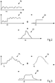
- 2 shows such a possible correlation.
- 2 shows a first course 16 of count values of a counter 8.
- the count values are shown continuously, but are preferably time-discrete values.
- the following diagrams all show continuous value curves, but can also be represented by time-discrete values.
- the course of the counter values depends on the
- this counter can, for example, supply a profile 18 of counted values. It can be seen that there is a jump in curve 18 at time t0. This jump can be caused by a subscriber 10 being switched on. The fluctuation in the counter values can be caused by power fluctuations of one subscriber 10 or other subscribers 10 arranged on the counter 8 .
- an expected value 20 can be assigned to such a control signal in this control device 12 .
- the expected value 20 which can also represent a progression of counted values, an effect on the subscriber 10, in particular the counted values at the counter 8, can be simulated by a specific control signal.
- correlation function 22 results in a maximum at time t0. This maximum at time t0 is due to the correlation of curve 18 with the expected value 20.
- a control command can not only be a switch-on and switch-off command, but can also contain a power specification for a subscriber 10, for example.
- a profile of an electrical power over a period of time can be known for a subscriber 10, so that, for example, beginning with the switch-on time t0, the profile of the electrical power and therefore the energy at the subscriber 10 can be known.
- Such a scenario is in the 3 shown.
- a profile 24 of counted values of a counter 8 at a subscriber 10 is shown.
- An expected value 26 in a control device 12 can be stored for the corresponding participant 10 .
- the expected value 26 represents the course of the power consumption and/or the energy of the participant 10.
- a corresponding participant 10 is controlled by the control device 12 and this participant 10 is connected to the counter 8, which supplies the counted values 24, then the profile of the counted values 24 is correlated with the expected value 26.
- a correlation function 28 shows a strong increase at time t0.
- the correlation between the curve 24 and the expected value 26 extends over a longer period of time, so that the correlation function 28 has a value over a longer period of time that can be above a limit value.
- a counter 8 can be assigned to a control device 12. Such a possible assignment can be in a system according to figs 1 , 4 , 5 , 6 take place.
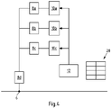
- a node 6 can according to 4 connect a meter 8d to a home distribution network.
- a number of meters 8a-c can be provided within a house distribution network, each of which has a subscriber 10a-c.
- the number of participants 10a-c and their assignment to counters 8a-c and the number of counters 8a-c are shown here purely as an example. In the 4 each participant 10 has exactly one counter 8 assigned to it.
- a control device 12 is provided with which the participants 10 can be controlled. There is a communication connection between the control device 12 and the meters 8a-d, but it is unknown in the control device 12 which of the participants 10 is arranged at which meter 8a-d and therefore also unknown which power flows at which meter 8a-d the Control device 12 can affect.
- the control device 12 In the control device 12 are data sets 28 with control commands and associated expected values for individual participants 10a-c.
- control device 12 In the control device 12 counted values of the counters 8a-d are received. In normal operation, ie without a control command to one of the participants 10a-c, the counts of the counters 8a-d fluctuate and are not comprehensible for the control device 12.
- an expected value can be loaded from the data record 28 for the corresponding control command.
- the control device 12 then correlates the count values received from the counters 8a-d with this expected value.
- the counted values of counter 8a correlate most with the expected value, so that the correlation function or the absolute value of the correlation function exceeds a limit value. Such an excess can be interpreted as an indication that the control device 12 is linked to the counter 8a via the subscriber 10a. In this respect, the counter 8a can be assigned to the control device 12 .
- the control device 12 receives counted values from the counter 8d. Since the counter 8d measures the power of the subscriber 10a that has changed as a result of the control command, the course of the counter values of the counter 8d will correlate with the expected values in the control device 12 and here too a correlation function or an amount of the correlation function will exceed a limit value and an assignment of the Counter 8d to the control device 12 can take place.
- control device 12 is also linked to the counters 8b-c.
- FIG 5 shows another embodiment.
- the control devices 12a-d are not assigned to all participants 10a-d, and therefore not to all meters 8a-e.
- the control device 12a can issue a control command for the subscriber 10a in the manner described.
- the control device 12a receives counted values of the counters 8a-e.
- the change in the counter values due to the control command correlates with the corresponding expected value in the control device 12a.
- the control device 12b-d also "see" the change in the count values on the counter 8e, this change does not correlate with expected values in the control devices 12b-d, since these have not issued a corresponding control command.
- the control device 12b can issue control commands for the subscriber 10b.
- the control device 12b can be assigned to the counter 8b by correlating the count values of the counters 8a-e with the expected values.
- the control device 12b can also control the subscriber 10c. With such an actuation, a corresponding expected value in the control device 12b can be used to determine that this can be assigned to the counter 8c.
- the control commands for the participants 10b and c also result in changed counts in the counter 8e.
- the count values of this counter 8e also lead to a correlation with the expected values in the control device 12b, so that the control device 12b can also be assigned to the counter 8e.
- control device 12a and the counters 8a and e applies equally to the control device 12c and the counters 8d and e.
- the control devices 12b, c can be cascaded with the control device 12d.
- the control device 12d can thus issue control commands for the participants 10b, c and d indirectly via the control device 12b and c.
- control device 12d Based on the control commands and the resulting change in the counter values, it can be determined in the control device 12d that it can be assigned to the counters 8b, c, d and e, but not to the counter 8a.
- control device 12a receives the counted values of the counters 8a-d. By issuing control commands for the participants 8a-c, it can be determined that the control device 12a can be assigned to the meters 8a-d.
- the control device 12b can control the control device 12a and, in addition to the counted values of the counters 8a-d, also receives the counted values of the counter 8e. By issuing control commands indirectly via the control device 12a, it can be determined that the control device 12b is assigned to the counters 8a-e. The control device 12b can thus influence power flows at the connection points of the counters 8a-e via corresponding control commands.
Landscapes
- Engineering & Computer Science (AREA)
- Power Engineering (AREA)
- Physics & Mathematics (AREA)
- General Physics & Mathematics (AREA)
- Selective Calling Equipment (AREA)
Claims (15)
- Procédé pour déterminer l'influence exercée par au moins un dispositif de commande, qui commande au moins un abonné exploité dans un réseau de distribution, sur les flux d'énergie mesurés par un compteur de consommation, et leur association mutuelle, comprenant :- envoyer des instructions de commande par le dispositif de commande à l'au moins un abonné,- recevoir des valeurs de comptage du compteur de consommation dans le dispositif de commande,- mettre en corrélation temporelle des valeurs de comptage reçues avec des valeurs attendues pour les valeurs de comptage, dépendantes des instructions de commande et mémorisées dans le dispositif de commande, et- déterminer de l'influence du compteur de consommation par le dispositif de commande en fonction de la corrélation et de l'association entre elles sur la base de l'influence.
- Procédé selon la revendication 1,
caractérisé en ce que- les valeurs de comptage reçues sont mises en corrélation en continu avec les valeurs attendues et que les associations sont modifiées de manière dynamique en fonction des corrélations actuelles. - Procédé selon la revendication 1 ou 2,
caractérisé en ce que- les valeurs attendues dépendent des instants d'émission des instructions de commande et/ou d'informations relatives à une puissance de l'abonné et/ou à un comportement de fonctionnement de l'abonné. - Procédé selon l'une des revendications précédentes,
caractérisé en ce que- les valeurs attendues comprennent une série temporelle de valeurs attendues et que les valeurs de comptage comprennent une série temporelle de valeurs mesurées, en particulier des valeurs de mesure d'énergie, des valeurs de mesure de puissance, des valeurs de mesure de courant et/ou des valeurs de mesure de tension. - Procédé selon l'une des revendications précédentes,
caractérisé en ce que- les instructions de commande comprennent des instructions d'activation et/ou de désactivation pour l'abonné et/ou que les instructions de commande comprennent au moins une exigence de puissance pour l'abonné. - Procédé selon l'une des revendications précédentes,
caractérisé en ce que- au moins en fonction de association, une puissance à un compteur de consommation respectif pouvant être influencée par le dispositif de commande aux abonnés est déterminée . - Procédé selon l'une des revendications précédentes,
caractérisé en ce que- au moins un compteur de consommation est associé à un point de connexion entre un réseau de distribution domestique et un réseau de distribution public et qu'une puissance pouvant être influencée au niveau du point de connexion est associée au dispositif de commande en fonction de l'association. - Procédé selon l'une des revendications précédentes,
caractérisé en ce que- le dispositif de commande reçoit une valeur d'exigence pour une modification d'une puissance à un point de connexion et commande au moins un abonné en fonction de la valeur d'exigence. - Procédé selon l'une des revendications précédentes,
caractérisé en ce que,- au moins trois dispositifs de commande sont connectés en cascade, de sorte qu'au moins un premier dispositif de commande de niveau supérieur commande au moins deux dispositifs de commande de niveau inférieur indépendants l'un de l'autre, et que l'association se fait à un des dispositifs de commande de niveau inférieur et à au moins un des dispositifs de commande de niveau supérieur. - Procédé selon l'une des revendications précédentes,
caractérisé en ce que- le compteur de consommation est un compteur d'énergie, en particulier un compteur d'énergie électrique, notamment un compteur intelligent ou un système de mesure intelligent. - Procédé selon l'une des revendications précédentes,
caractérisé en ce que- le compteur de consommation est en liaison de communication avec le dispositif de commande. - Procédé selon l'une des revendications précédentes,
caractérisé en ce que- au moins un compteur de consommation est disposé dans un réseau de distribution domestique et/ou qu'au moins un compteur de consommation est disposé dans un réseau de distribution public. - Procédé selon l'une des revendications précédentes,
caractérisé en ce que- l'abonné est un consommateur, en particulier un consommateur électrique et/ou que l'abonné est un producteur, en particulier un producteur électrique et/ou que l'abonné est un accumulateur, en particulier un accumulateur électrique. - Procédé selon l'une des revendications précédentes,
caractérisé en ce que- le dispositif de commande est un système de gestion de l'énergie. - Système configuré pour effectuer un procédé selon l'une des revendications précédentes, comprenant un dispositif de commande, au moins un compteur de consommation et un abonné dans un réseau de distribution, où le dispositif de commande est en liaison active avec l'abonné et le compteur de consommation est en liaison de communication avec le dispositif de commande.
Applications Claiming Priority (1)
| Application Number | Priority Date | Filing Date | Title |
|---|---|---|---|
| DE102019110447.5A DE102019110447A1 (de) | 2019-04-23 | 2019-04-23 | Verfahren und System zur Erstellung einer Zuordnung zwischen einem Verbrauchsmengenzähler und einer Steuereinrichtung |
Publications (2)
| Publication Number | Publication Date |
|---|---|
| EP3731370A1 EP3731370A1 (fr) | 2020-10-28 |
| EP3731370B1 true EP3731370B1 (fr) | 2022-08-17 |
Family
ID=69960311
Family Applications (1)
| Application Number | Title | Priority Date | Filing Date |
|---|---|---|---|
| EP20165067.8A Active EP3731370B1 (fr) | 2019-04-23 | 2020-03-24 | Procédé et système de génération d'une attribution entre un compteur de consommation et un dispositif de commande |
Country Status (2)
| Country | Link |
|---|---|
| EP (1) | EP3731370B1 (fr) |
| DE (1) | DE102019110447A1 (fr) |
Family Cites Families (6)
| Publication number | Priority date | Publication date | Assignee | Title |
|---|---|---|---|---|
| DE102005047901A1 (de) * | 2005-09-30 | 2007-04-19 | Schering Ag | Vorrichtung zur Identifizierung von Verbrauchern in einem elektrischen Netz und Verfahren zum Betreiben der Vorrichtung |
| EP2865063B1 (fr) * | 2012-06-22 | 2016-04-27 | SMA Solar Technology AG | Procédé pour determiner la topologie d'un réseau et sa gestion |
| CN105264735A (zh) * | 2013-03-15 | 2016-01-20 | 道明尼资源公司 | 使用基于ami的数据控制和分析使电压最佳化 |
| GB2519632A (en) * | 2013-08-16 | 2015-04-29 | Andrew Howe | System And Method For Providing Electrical Supply Grid Service |
| DE102016101021A1 (de) * | 2016-01-21 | 2017-07-27 | Gelsenwasser Ag | Verfahren und Vorrichtung zur Erkennung von in einem Versorgungsnetz vorhandenen Verbrauchern |
| DE102016108519A1 (de) * | 2016-05-09 | 2017-11-09 | Rwe International Se | Nichtinvasive Lastbeobachtung |
-
2019
- 2019-04-23 DE DE102019110447.5A patent/DE102019110447A1/de not_active Withdrawn
-
2020
- 2020-03-24 EP EP20165067.8A patent/EP3731370B1/fr active Active
Also Published As
| Publication number | Publication date |
|---|---|
| EP3731370A1 (fr) | 2020-10-28 |
| DE102019110447A1 (de) | 2020-10-29 |
Similar Documents
| Publication | Publication Date | Title |
|---|---|---|
| EP2633600B1 (fr) | Procédé de détection de données à cycle court, pour la surveillance de l'énergie et pour la commande de réseau dans le système de compteur intelligent/réseau électrique intelligent à l'aide d'un logiciel médiateur intelligent distribué | |
| EP2865063A2 (fr) | Établissement de plan de réseau et gestion du fonctionnement | |
| EP3336995B1 (fr) | Procédé, dispositif de commande et système de détermination de valeurs d'état pour décrire des états de fonctionnement dans un sous-réseau d'un réseau de distribution d'énergie | |
| DE102010026299A1 (de) | Verfahren zur Steuerung von PV-Anlagen in einem Stromversorgungsnetz | |
| EP3561983A1 (fr) | Procédé de fonctionnement d'un système d'alimentation en énergie | |
| DE102013222277A1 (de) | Steuerung von dezentralen Energieerzeugern und/oder Verbrauchern in einem elektrischen Verbundnetz | |
| EP3284152B1 (fr) | Commande de transfert d'énergie entre un réseau d'alimentation en énergie et des dispositifs d'utilisateur final sur la base du flux d'énergie et de la qualité du réseau | |
| DE102014217929A1 (de) | Energiemanagementsystem zur Steuerung einer Einrichtung, Computersoftwareprodukt und Verfahren zur Steuerung einer Einrichtung | |
| EP2828945B1 (fr) | Procédé et dispositif permettant de réguler une tension dans un réseau de distribution | |
| EP3731370B1 (fr) | Procédé et système de génération d'une attribution entre un compteur de consommation et un dispositif de commande | |
| DE102016101021A1 (de) | Verfahren und Vorrichtung zur Erkennung von in einem Versorgungsnetz vorhandenen Verbrauchern | |
| EP2834898B1 (fr) | Procédé de détermination de points de mesure dans des réseaux à basse tension et sous-système de gestion de réseau servant à mettre en oeuvre ce procédé | |
| EP2854250A2 (fr) | Procédé d'analyse d'un signal de composition agrégé et de commande de charge dans un système d'alimentation électrique | |
| DE19817191C2 (de) | Verfahren zum Regeln der Gesamtleistung von energietechnischen Anlagen, insbesondere einer Gruppe von elektrischen Verbrauchern | |
| EP2763264A1 (fr) | Dispositif de commande d'un réseau électrique intelligent | |
| DE102010023113A1 (de) | Kraftwerksüberwachung und -regelung | |
| EP2820735A1 (fr) | Appareil électrique et procédé pour le pilotage d'un générateur d'énergie électrique | |
| EP2618458B1 (fr) | Procédé destiné à détecter des états de commutation dans des réseaux d'alimentation en énergie et système destiné à l'exécution du procédé | |
| EP3440757B1 (fr) | Surveillance de la mise en service et de la plausibilité de données d'un capteur de mesure de puissance dans un réseau de distribution électrique | |
| AT514766B1 (de) | Verfahren zur Stabilisierung eines Energieverteilnetzes | |
| EP3477262B1 (fr) | Procédé de détection de la consommation en fonction de la charge de différentes sources de courant auprès des clients | |
| EP3958470A1 (fr) | Procédé de transfert de données dans un réseau basse tension | |
| DE102014222662A1 (de) | Verfahren zur Datenanreicherung von Messdatensätzen eines Niederspannungsnetzes | |
| EP3268755B1 (fr) | Système servant à déterminer la consommation individuelle d'énergie d'un consommateur | |
| EP4531238A1 (fr) | Amélioration de la qualité de techniques d'estimation d'état de réseau basse tension par vérification de topologie assistée par simulation |
Legal Events
| Date | Code | Title | Description |
|---|---|---|---|
| PUAI | Public reference made under article 153(3) epc to a published international application that has entered the european phase |
Free format text: ORIGINAL CODE: 0009012 |
|
| STAA | Information on the status of an ep patent application or granted ep patent |
Free format text: STATUS: THE APPLICATION HAS BEEN PUBLISHED |
|
| AK | Designated contracting states |
Kind code of ref document: A1 Designated state(s): AL AT BE BG CH CY CZ DE DK EE ES FI FR GB GR HR HU IE IS IT LI LT LU LV MC MK MT NL NO PL PT RO RS SE SI SK SM TR |
|
| AX | Request for extension of the european patent |
Extension state: BA ME |
|
| STAA | Information on the status of an ep patent application or granted ep patent |
Free format text: STATUS: REQUEST FOR EXAMINATION WAS MADE |
|
| 17P | Request for examination filed |
Effective date: 20210427 |
|
| RBV | Designated contracting states (corrected) |
Designated state(s): AL AT BE BG CH CY CZ DE DK EE ES FI FR GB GR HR HU IE IS IT LI LT LU LV MC MK MT NL NO PL PT RO RS SE SI SK SM TR |
|
| GRAP | Despatch of communication of intention to grant a patent |
Free format text: ORIGINAL CODE: EPIDOSNIGR1 |
|
| STAA | Information on the status of an ep patent application or granted ep patent |
Free format text: STATUS: GRANT OF PATENT IS INTENDED |
|
| INTG | Intention to grant announced |
Effective date: 20220317 |
|
| GRAS | Grant fee paid |
Free format text: ORIGINAL CODE: EPIDOSNIGR3 |
|
| GRAA | (expected) grant |
Free format text: ORIGINAL CODE: 0009210 |
|
| STAA | Information on the status of an ep patent application or granted ep patent |
Free format text: STATUS: THE PATENT HAS BEEN GRANTED |
|
| AK | Designated contracting states |
Kind code of ref document: B1 Designated state(s): AL AT BE BG CH CY CZ DE DK EE ES FI FR GB GR HR HU IE IS IT LI LT LU LV MC MK MT NL NO PL PT RO RS SE SI SK SM TR |
|
| REG | Reference to a national code |
Ref country code: CH Ref legal event code: EP |
|
| REG | Reference to a national code |
Ref country code: DE Ref legal event code: R096 Ref document number: 502020001521 Country of ref document: DE |
|
| REG | Reference to a national code |
Ref country code: IE Ref legal event code: FG4D Free format text: LANGUAGE OF EP DOCUMENT: GERMAN |
|
| REG | Reference to a national code |
Ref country code: AT Ref legal event code: REF Ref document number: 1512806 Country of ref document: AT Kind code of ref document: T Effective date: 20220915 |
|
| REG | Reference to a national code |
Ref country code: NL Ref legal event code: FP |
|
| REG | Reference to a national code |
Ref country code: LT Ref legal event code: MG9D |
|
| PG25 | Lapsed in a contracting state [announced via postgrant information from national office to epo] |
Ref country code: SE Free format text: LAPSE BECAUSE OF FAILURE TO SUBMIT A TRANSLATION OF THE DESCRIPTION OR TO PAY THE FEE WITHIN THE PRESCRIBED TIME-LIMIT Effective date: 20220817 Ref country code: RS Free format text: LAPSE BECAUSE OF FAILURE TO SUBMIT A TRANSLATION OF THE DESCRIPTION OR TO PAY THE FEE WITHIN THE PRESCRIBED TIME-LIMIT Effective date: 20220817 Ref country code: PT Free format text: LAPSE BECAUSE OF FAILURE TO SUBMIT A TRANSLATION OF THE DESCRIPTION OR TO PAY THE FEE WITHIN THE PRESCRIBED TIME-LIMIT Effective date: 20221219 Ref country code: NO Free format text: LAPSE BECAUSE OF FAILURE TO SUBMIT A TRANSLATION OF THE DESCRIPTION OR TO PAY THE FEE WITHIN THE PRESCRIBED TIME-LIMIT Effective date: 20221117 Ref country code: LV Free format text: LAPSE BECAUSE OF FAILURE TO SUBMIT A TRANSLATION OF THE DESCRIPTION OR TO PAY THE FEE WITHIN THE PRESCRIBED TIME-LIMIT Effective date: 20220817 Ref country code: LT Free format text: LAPSE BECAUSE OF FAILURE TO SUBMIT A TRANSLATION OF THE DESCRIPTION OR TO PAY THE FEE WITHIN THE PRESCRIBED TIME-LIMIT Effective date: 20220817 Ref country code: FI Free format text: LAPSE BECAUSE OF FAILURE TO SUBMIT A TRANSLATION OF THE DESCRIPTION OR TO PAY THE FEE WITHIN THE PRESCRIBED TIME-LIMIT Effective date: 20220817 |
|
| PG25 | Lapsed in a contracting state [announced via postgrant information from national office to epo] |
Ref country code: PL Free format text: LAPSE BECAUSE OF FAILURE TO SUBMIT A TRANSLATION OF THE DESCRIPTION OR TO PAY THE FEE WITHIN THE PRESCRIBED TIME-LIMIT Effective date: 20220817 Ref country code: IS Free format text: LAPSE BECAUSE OF FAILURE TO SUBMIT A TRANSLATION OF THE DESCRIPTION OR TO PAY THE FEE WITHIN THE PRESCRIBED TIME-LIMIT Effective date: 20221217 Ref country code: HR Free format text: LAPSE BECAUSE OF FAILURE TO SUBMIT A TRANSLATION OF THE DESCRIPTION OR TO PAY THE FEE WITHIN THE PRESCRIBED TIME-LIMIT Effective date: 20220817 Ref country code: GR Free format text: LAPSE BECAUSE OF FAILURE TO SUBMIT A TRANSLATION OF THE DESCRIPTION OR TO PAY THE FEE WITHIN THE PRESCRIBED TIME-LIMIT Effective date: 20221118 |
|
| PG25 | Lapsed in a contracting state [announced via postgrant information from national office to epo] |
Ref country code: SM Free format text: LAPSE BECAUSE OF FAILURE TO SUBMIT A TRANSLATION OF THE DESCRIPTION OR TO PAY THE FEE WITHIN THE PRESCRIBED TIME-LIMIT Effective date: 20220817 Ref country code: RO Free format text: LAPSE BECAUSE OF FAILURE TO SUBMIT A TRANSLATION OF THE DESCRIPTION OR TO PAY THE FEE WITHIN THE PRESCRIBED TIME-LIMIT Effective date: 20220817 Ref country code: ES Free format text: LAPSE BECAUSE OF FAILURE TO SUBMIT A TRANSLATION OF THE DESCRIPTION OR TO PAY THE FEE WITHIN THE PRESCRIBED TIME-LIMIT Effective date: 20220817 Ref country code: DK Free format text: LAPSE BECAUSE OF FAILURE TO SUBMIT A TRANSLATION OF THE DESCRIPTION OR TO PAY THE FEE WITHIN THE PRESCRIBED TIME-LIMIT Effective date: 20220817 Ref country code: CZ Free format text: LAPSE BECAUSE OF FAILURE TO SUBMIT A TRANSLATION OF THE DESCRIPTION OR TO PAY THE FEE WITHIN THE PRESCRIBED TIME-LIMIT Effective date: 20220817 |
|
| REG | Reference to a national code |
Ref country code: DE Ref legal event code: R097 Ref document number: 502020001521 Country of ref document: DE |
|
| PG25 | Lapsed in a contracting state [announced via postgrant information from national office to epo] |
Ref country code: SK Free format text: LAPSE BECAUSE OF FAILURE TO SUBMIT A TRANSLATION OF THE DESCRIPTION OR TO PAY THE FEE WITHIN THE PRESCRIBED TIME-LIMIT Effective date: 20220817 Ref country code: EE Free format text: LAPSE BECAUSE OF FAILURE TO SUBMIT A TRANSLATION OF THE DESCRIPTION OR TO PAY THE FEE WITHIN THE PRESCRIBED TIME-LIMIT Effective date: 20220817 |
|
| PLBE | No opposition filed within time limit |
Free format text: ORIGINAL CODE: 0009261 |
|
| STAA | Information on the status of an ep patent application or granted ep patent |
Free format text: STATUS: NO OPPOSITION FILED WITHIN TIME LIMIT |
|
| PG25 | Lapsed in a contracting state [announced via postgrant information from national office to epo] |
Ref country code: AL Free format text: LAPSE BECAUSE OF FAILURE TO SUBMIT A TRANSLATION OF THE DESCRIPTION OR TO PAY THE FEE WITHIN THE PRESCRIBED TIME-LIMIT Effective date: 20220817 |
|
| 26N | No opposition filed |
Effective date: 20230519 |
|
| PG25 | Lapsed in a contracting state [announced via postgrant information from national office to epo] |
Ref country code: SI Free format text: LAPSE BECAUSE OF FAILURE TO SUBMIT A TRANSLATION OF THE DESCRIPTION OR TO PAY THE FEE WITHIN THE PRESCRIBED TIME-LIMIT Effective date: 20220817 |
|
| PG25 | Lapsed in a contracting state [announced via postgrant information from national office to epo] |
Ref country code: MC Free format text: LAPSE BECAUSE OF FAILURE TO SUBMIT A TRANSLATION OF THE DESCRIPTION OR TO PAY THE FEE WITHIN THE PRESCRIBED TIME-LIMIT Effective date: 20220817 |
|
| REG | Reference to a national code |
Ref country code: IE Ref legal event code: MM4A |
|
| PG25 | Lapsed in a contracting state [announced via postgrant information from national office to epo] |
Ref country code: IE Free format text: LAPSE BECAUSE OF NON-PAYMENT OF DUE FEES Effective date: 20230324 |
|
| PG25 | Lapsed in a contracting state [announced via postgrant information from national office to epo] |
Ref country code: IT Free format text: LAPSE BECAUSE OF FAILURE TO SUBMIT A TRANSLATION OF THE DESCRIPTION OR TO PAY THE FEE WITHIN THE PRESCRIBED TIME-LIMIT Effective date: 20220817 |
|
| PG25 | Lapsed in a contracting state [announced via postgrant information from national office to epo] |
Ref country code: BG Free format text: LAPSE BECAUSE OF FAILURE TO SUBMIT A TRANSLATION OF THE DESCRIPTION OR TO PAY THE FEE WITHIN THE PRESCRIBED TIME-LIMIT Effective date: 20220817 |
|
| PG25 | Lapsed in a contracting state [announced via postgrant information from national office to epo] |
Ref country code: BG Free format text: LAPSE BECAUSE OF FAILURE TO SUBMIT A TRANSLATION OF THE DESCRIPTION OR TO PAY THE FEE WITHIN THE PRESCRIBED TIME-LIMIT Effective date: 20220817 |
|
| PGFP | Annual fee paid to national office [announced via postgrant information from national office to epo] |
Ref country code: CH Payment date: 20250401 Year of fee payment: 6 |
|
| PG25 | Lapsed in a contracting state [announced via postgrant information from national office to epo] |
Ref country code: CY Free format text: LAPSE BECAUSE OF FAILURE TO SUBMIT A TRANSLATION OF THE DESCRIPTION OR TO PAY THE FEE WITHIN THE PRESCRIBED TIME-LIMIT; INVALID AB INITIO Effective date: 20200324 |
|
| PG25 | Lapsed in a contracting state [announced via postgrant information from national office to epo] |
Ref country code: HU Free format text: LAPSE BECAUSE OF FAILURE TO SUBMIT A TRANSLATION OF THE DESCRIPTION OR TO PAY THE FEE WITHIN THE PRESCRIBED TIME-LIMIT; INVALID AB INITIO Effective date: 20200324 |
|
| PG25 | Lapsed in a contracting state [announced via postgrant information from national office to epo] |
Ref country code: TR Free format text: LAPSE BECAUSE OF FAILURE TO SUBMIT A TRANSLATION OF THE DESCRIPTION OR TO PAY THE FEE WITHIN THE PRESCRIBED TIME-LIMIT Effective date: 20220817 |
|
| REG | Reference to a national code |
Ref country code: CH Ref legal event code: U11 Free format text: ST27 STATUS EVENT CODE: U-0-0-U10-U11 (AS PROVIDED BY THE NATIONAL OFFICE) Effective date: 20260401 |
|
| PGFP | Annual fee paid to national office [announced via postgrant information from national office to epo] |
Ref country code: GB Payment date: 20260324 Year of fee payment: 7 |
|
| PGFP | Annual fee paid to national office [announced via postgrant information from national office to epo] |
Ref country code: DE Payment date: 20260320 Year of fee payment: 7 |
|
| PGFP | Annual fee paid to national office [announced via postgrant information from national office to epo] |
Ref country code: AT Payment date: 20260319 Year of fee payment: 7 |
|
| PGFP | Annual fee paid to national office [announced via postgrant information from national office to epo] |
Ref country code: LU Payment date: 20260320 Year of fee payment: 7 Ref country code: BE Payment date: 20260323 Year of fee payment: 7 |
|
| PGFP | Annual fee paid to national office [announced via postgrant information from national office to epo] |
Ref country code: NL Payment date: 20260323 Year of fee payment: 7 |
|
| PGFP | Annual fee paid to national office [announced via postgrant information from national office to epo] |
Ref country code: FR Payment date: 20260325 Year of fee payment: 7 |