EP3731405B1 - Système et procédé de commande de la puissance réactive d'une éolienne par variation de la fréquence de commutation d'un convertisseur latéral de rotor - Google Patents
Système et procédé de commande de la puissance réactive d'une éolienne par variation de la fréquence de commutation d'un convertisseur latéral de rotor Download PDFInfo
- Publication number
- EP3731405B1 EP3731405B1 EP20169891.7A EP20169891A EP3731405B1 EP 3731405 B1 EP3731405 B1 EP 3731405B1 EP 20169891 A EP20169891 A EP 20169891A EP 3731405 B1 EP3731405 B1 EP 3731405B1
- Authority
- EP
- European Patent Office
- Prior art keywords
- switching frequency
- reactive power
- power
- generator
- wind turbine
- Prior art date
- Legal status (The legal status is an assumption and is not a legal conclusion. Google has not performed a legal analysis and makes no representation as to the accuracy of the status listed.)
- Active
Links
Images



Classifications
-
- F—MECHANICAL ENGINEERING; LIGHTING; HEATING; WEAPONS; BLASTING
- F03—MACHINES OR ENGINES FOR LIQUIDS; WIND, SPRING, OR WEIGHT MOTORS; PRODUCING MECHANICAL POWER OR A REACTIVE PROPULSIVE THRUST, NOT OTHERWISE PROVIDED FOR
- F03D—WIND MOTORS
- F03D7/00—Controlling wind motors
- F03D7/02—Controlling wind motors the wind motors having rotation axis substantially parallel to the air flow entering the rotor
- F03D7/04—Automatic control; Regulation
- F03D7/042—Automatic control; Regulation by means of an electrical or electronic controller
-
- H—ELECTRICITY
- H02—GENERATION; CONVERSION OR DISTRIBUTION OF ELECTRIC POWER
- H02P—CONTROL OR REGULATION OF ELECTRIC MOTORS, ELECTRIC GENERATORS OR DYNAMO-ELECTRIC CONVERTERS; CONTROLLING TRANSFORMERS, REACTORS OR CHOKE COILS
- H02P9/00—Arrangements for controlling electric generators for the purpose of obtaining a desired output
- H02P9/007—Control circuits for doubly fed generators
-
- F—MECHANICAL ENGINEERING; LIGHTING; HEATING; WEAPONS; BLASTING
- F03—MACHINES OR ENGINES FOR LIQUIDS; WIND, SPRING, OR WEIGHT MOTORS; PRODUCING MECHANICAL POWER OR A REACTIVE PROPULSIVE THRUST, NOT OTHERWISE PROVIDED FOR
- F03D—WIND MOTORS
- F03D7/00—Controlling wind motors
- F03D7/02—Controlling wind motors the wind motors having rotation axis substantially parallel to the air flow entering the rotor
- F03D7/0272—Controlling wind motors the wind motors having rotation axis substantially parallel to the air flow entering the rotor by measures acting on the electrical generator
-
- F—MECHANICAL ENGINEERING; LIGHTING; HEATING; WEAPONS; BLASTING
- F03—MACHINES OR ENGINES FOR LIQUIDS; WIND, SPRING, OR WEIGHT MOTORS; PRODUCING MECHANICAL POWER OR A REACTIVE PROPULSIVE THRUST, NOT OTHERWISE PROVIDED FOR
- F03D—WIND MOTORS
- F03D7/00—Controlling wind motors
- F03D7/02—Controlling wind motors the wind motors having rotation axis substantially parallel to the air flow entering the rotor
- F03D7/028—Controlling wind motors the wind motors having rotation axis substantially parallel to the air flow entering the rotor controlling wind motor output power
- F03D7/0284—Controlling wind motors the wind motors having rotation axis substantially parallel to the air flow entering the rotor controlling wind motor output power in relation to the state of the electric grid
-
- F—MECHANICAL ENGINEERING; LIGHTING; HEATING; WEAPONS; BLASTING
- F03—MACHINES OR ENGINES FOR LIQUIDS; WIND, SPRING, OR WEIGHT MOTORS; PRODUCING MECHANICAL POWER OR A REACTIVE PROPULSIVE THRUST, NOT OTHERWISE PROVIDED FOR
- F03D—WIND MOTORS
- F03D9/00—Adaptations of wind motors for special use; Combinations of wind motors with apparatus driven thereby; Wind motors specially adapted for installation in particular locations
- F03D9/20—Wind motors characterised by the driven apparatus
- F03D9/25—Wind motors characterised by the driven apparatus the apparatus being an electrical generator
- F03D9/255—Wind motors characterised by the driven apparatus the apparatus being an electrical generator connected to electrical distribution networks; Arrangements therefor
-
- H—ELECTRICITY
- H02—GENERATION; CONVERSION OR DISTRIBUTION OF ELECTRIC POWER
- H02J—ELECTRIC POWER NETWORKS; CIRCUIT ARRANGEMENTS OR SYSTEMS FOR SUPPLYING OR DISTRIBUTING ELECTRIC POWER; SYSTEMS FOR STORING ELECTRIC ENERGY
- H02J3/00—Circuit arrangements for AC mains or AC distribution networks
- H02J3/12—Arrangements for adjusting voltage in AC networks by changing a characteristic of the network load
- H02J3/16—Arrangements for adjusting voltage in AC networks by changing a characteristic of the network load by adjustment of reactive power
-
- H—ELECTRICITY
- H02—GENERATION; CONVERSION OR DISTRIBUTION OF ELECTRIC POWER
- H02J—ELECTRIC POWER NETWORKS; CIRCUIT ARRANGEMENTS OR SYSTEMS FOR SUPPLYING OR DISTRIBUTING ELECTRIC POWER; SYSTEMS FOR STORING ELECTRIC ENERGY
- H02J3/00—Circuit arrangements for AC mains or AC distribution networks
- H02J3/18—Arrangements for adjusting, eliminating or compensating reactive power in networks
- H02J3/1821—Arrangements for adjusting, eliminating or compensating reactive power in networks using shunt compensators
- H02J3/1835—Arrangements for adjusting, eliminating or compensating reactive power in networks using shunt compensators with stepless control
- H02J3/1842—Arrangements for adjusting, eliminating or compensating reactive power in networks using shunt compensators with stepless control having reactive elements actively controlled by bridge converters, e.g. active filters or static compensators [STATCOM]
-
- H—ELECTRICITY
- H02—GENERATION; CONVERSION OR DISTRIBUTION OF ELECTRIC POWER
- H02J—ELECTRIC POWER NETWORKS; CIRCUIT ARRANGEMENTS OR SYSTEMS FOR SUPPLYING OR DISTRIBUTING ELECTRIC POWER; SYSTEMS FOR STORING ELECTRIC ENERGY
- H02J3/00—Circuit arrangements for AC mains or AC distribution networks
- H02J3/38—Arrangements for feeding a single network from two or more generators or sources in parallel; Arrangements for feeding already energised networks from additional generators or sources in parallel
- H02J3/381—Dispersed generators
-
- H—ELECTRICITY
- H02—GENERATION; CONVERSION OR DISTRIBUTION OF ELECTRIC POWER
- H02M—APPARATUS FOR CONVERSION BETWEEN AC AND AC, BETWEEN AC AND DC, OR BETWEEN DC AND DC, AND FOR USE WITH MAINS OR SIMILAR POWER SUPPLY SYSTEMS; CONVERSION OF DC OR AC INPUT POWER INTO SURGE OUTPUT POWER; CONTROL OR REGULATION THEREOF
- H02M1/00—Details of apparatus for conversion
- H02M1/12—Arrangements for reducing harmonics from AC input or output
-
- H—ELECTRICITY
- H02—GENERATION; CONVERSION OR DISTRIBUTION OF ELECTRIC POWER
- H02M—APPARATUS FOR CONVERSION BETWEEN AC AND AC, BETWEEN AC AND DC, OR BETWEEN DC AND DC, AND FOR USE WITH MAINS OR SIMILAR POWER SUPPLY SYSTEMS; CONVERSION OF DC OR AC INPUT POWER INTO SURGE OUTPUT POWER; CONTROL OR REGULATION THEREOF
- H02M1/00—Details of apparatus for conversion
- H02M1/42—Circuits or arrangements for compensating for or adjusting power factor in converters or inverters
-
- H—ELECTRICITY
- H02—GENERATION; CONVERSION OR DISTRIBUTION OF ELECTRIC POWER
- H02M—APPARATUS FOR CONVERSION BETWEEN AC AND AC, BETWEEN AC AND DC, OR BETWEEN DC AND DC, AND FOR USE WITH MAINS OR SIMILAR POWER SUPPLY SYSTEMS; CONVERSION OF DC OR AC INPUT POWER INTO SURGE OUTPUT POWER; CONTROL OR REGULATION THEREOF
- H02M5/00—Conversion of AC power input into AC power output, e.g. for change of voltage, for change of frequency, for change of number of phases
- H02M5/40—Conversion of AC power input into AC power output, e.g. for change of voltage, for change of frequency, for change of number of phases with intermediate conversion into DC
- H02M5/42—Conversion of AC power input into AC power output, e.g. for change of voltage, for change of frequency, for change of number of phases with intermediate conversion into DC by static converters
- H02M5/44—Conversion of AC power input into AC power output, e.g. for change of voltage, for change of frequency, for change of number of phases with intermediate conversion into DC by static converters using discharge tubes or semiconductor devices to convert the intermediate DC into AC
- H02M5/453—Conversion of AC power input into AC power output, e.g. for change of voltage, for change of frequency, for change of number of phases with intermediate conversion into DC by static converters using discharge tubes or semiconductor devices to convert the intermediate DC into AC using devices of a triode or transistor type requiring continuous application of a control signal
- H02M5/458—Conversion of AC power input into AC power output, e.g. for change of voltage, for change of frequency, for change of number of phases with intermediate conversion into DC by static converters using discharge tubes or semiconductor devices to convert the intermediate DC into AC using devices of a triode or transistor type requiring continuous application of a control signal using semiconductor devices only
- H02M5/4585—Conversion of AC power input into AC power output, e.g. for change of voltage, for change of frequency, for change of number of phases with intermediate conversion into DC by static converters using discharge tubes or semiconductor devices to convert the intermediate DC into AC using devices of a triode or transistor type requiring continuous application of a control signal using semiconductor devices only having a rectifier with controlled elements
-
- H—ELECTRICITY
- H02—GENERATION; CONVERSION OR DISTRIBUTION OF ELECTRIC POWER
- H02P—CONTROL OR REGULATION OF ELECTRIC MOTORS, ELECTRIC GENERATORS OR DYNAMO-ELECTRIC CONVERTERS; CONTROLLING TRANSFORMERS, REACTORS OR CHOKE COILS
- H02P9/00—Arrangements for controlling electric generators for the purpose of obtaining a desired output
- H02P9/10—Control effected upon generator excitation circuit to reduce harmful effects of overloads or transients, e.g. sudden application of load, sudden removal of load, sudden change of load
- H02P9/105—Control effected upon generator excitation circuit to reduce harmful effects of overloads or transients, e.g. sudden application of load, sudden removal of load, sudden change of load for increasing the stability
-
- H—ELECTRICITY
- H02—GENERATION; CONVERSION OR DISTRIBUTION OF ELECTRIC POWER
- H02P—CONTROL OR REGULATION OF ELECTRIC MOTORS, ELECTRIC GENERATORS OR DYNAMO-ELECTRIC CONVERTERS; CONTROLLING TRANSFORMERS, REACTORS OR CHOKE COILS
- H02P9/00—Arrangements for controlling electric generators for the purpose of obtaining a desired output
- H02P9/14—Arrangements for controlling electric generators for the purpose of obtaining a desired output by variation of field
- H02P9/26—Arrangements for controlling electric generators for the purpose of obtaining a desired output by variation of field using discharge tubes or semiconductor devices
- H02P9/30—Arrangements for controlling electric generators for the purpose of obtaining a desired output by variation of field using discharge tubes or semiconductor devices using semiconductor devices
-
- H—ELECTRICITY
- H02—GENERATION; CONVERSION OR DISTRIBUTION OF ELECTRIC POWER
- H02P—CONTROL OR REGULATION OF ELECTRIC MOTORS, ELECTRIC GENERATORS OR DYNAMO-ELECTRIC CONVERTERS; CONTROLLING TRANSFORMERS, REACTORS OR CHOKE COILS
- H02P9/00—Arrangements for controlling electric generators for the purpose of obtaining a desired output
- H02P9/42—Arrangements for controlling electric generators for the purpose of obtaining a desired output to obtain desired frequency without varying speed of the generator
-
- F—MECHANICAL ENGINEERING; LIGHTING; HEATING; WEAPONS; BLASTING
- F05—INDEXING SCHEMES RELATING TO ENGINES OR PUMPS IN VARIOUS SUBCLASSES OF CLASSES F01-F04
- F05B—INDEXING SCHEME RELATING TO WIND, SPRING, WEIGHT, INERTIA OR LIKE MOTORS, TO MACHINES OR ENGINES FOR LIQUIDS COVERED BY SUBCLASSES F03B, F03D AND F03G
- F05B2220/00—Application
- F05B2220/70—Application in combination with
- F05B2220/706—Application in combination with an electrical generator
-
- F—MECHANICAL ENGINEERING; LIGHTING; HEATING; WEAPONS; BLASTING
- F05—INDEXING SCHEMES RELATING TO ENGINES OR PUMPS IN VARIOUS SUBCLASSES OF CLASSES F01-F04
- F05B—INDEXING SCHEME RELATING TO WIND, SPRING, WEIGHT, INERTIA OR LIKE MOTORS, TO MACHINES OR ENGINES FOR LIQUIDS COVERED BY SUBCLASSES F03B, F03D AND F03G
- F05B2270/00—Control
- F05B2270/30—Control parameters, e.g. input parameters
- F05B2270/327—Rotor or generator speeds
-
- F—MECHANICAL ENGINEERING; LIGHTING; HEATING; WEAPONS; BLASTING
- F05—INDEXING SCHEMES RELATING TO ENGINES OR PUMPS IN VARIOUS SUBCLASSES OF CLASSES F01-F04
- F05B—INDEXING SCHEME RELATING TO WIND, SPRING, WEIGHT, INERTIA OR LIKE MOTORS, TO MACHINES OR ENGINES FOR LIQUIDS COVERED BY SUBCLASSES F03B, F03D AND F03G
- F05B2270/00—Control
- F05B2270/40—Type of control system
- F05B2270/402—Type of control system passive or reactive, e.g. using large wind vanes
-
- H—ELECTRICITY
- H02—GENERATION; CONVERSION OR DISTRIBUTION OF ELECTRIC POWER
- H02J—ELECTRIC POWER NETWORKS; CIRCUIT ARRANGEMENTS OR SYSTEMS FOR SUPPLYING OR DISTRIBUTING ELECTRIC POWER; SYSTEMS FOR STORING ELECTRIC ENERGY
- H02J2101/00—Supply or distribution of decentralised, dispersed or local electric power generation
- H02J2101/20—Dispersed power generation using renewable energy sources
- H02J2101/28—Wind energy
-
- H—ELECTRICITY
- H02—GENERATION; CONVERSION OR DISTRIBUTION OF ELECTRIC POWER
- H02P—CONTROL OR REGULATION OF ELECTRIC MOTORS, ELECTRIC GENERATORS OR DYNAMO-ELECTRIC CONVERTERS; CONTROLLING TRANSFORMERS, REACTORS OR CHOKE COILS
- H02P2101/00—Special adaptation of control arrangements for generators
- H02P2101/15—Special adaptation of control arrangements for generators for wind-driven turbines
-
- Y—GENERAL TAGGING OF NEW TECHNOLOGICAL DEVELOPMENTS; GENERAL TAGGING OF CROSS-SECTIONAL TECHNOLOGIES SPANNING OVER SEVERAL SECTIONS OF THE IPC; TECHNICAL SUBJECTS COVERED BY FORMER USPC CROSS-REFERENCE ART COLLECTIONS [XRACs] AND DIGESTS
- Y02—TECHNOLOGIES OR APPLICATIONS FOR MITIGATION OR ADAPTATION AGAINST CLIMATE CHANGE
- Y02E—REDUCTION OF GREENHOUSE GAS [GHG] EMISSIONS, RELATED TO ENERGY GENERATION, TRANSMISSION OR DISTRIBUTION
- Y02E40/00—Technologies for an efficient electrical power generation, transmission or distribution
- Y02E40/30—Reactive power compensation
Definitions
- Each of the RSC and the LSC typically includes a bank of pulse width modulated switching devices, for example insulated gate bipolar transistors (IGBT modules).
- IGBT modules insulated gate bipolar transistors
- the LSC converts the DC power on the DC link into AC output power that is combined with the power from the generator stator to provide multi-phase power having a frequency maintained substantially at the frequency of the electrical grid bus (e.g. 50 HZ or 60 HZ).
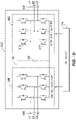
- the above system is generally referred to as a doubly-fed induction generator (DFIG) system, whose operating principles include that the rotor windings are connected to the grid via slip rings and the power converter controls rotor current and voltage. Control of rotor voltage and current enables the generator to remain synchronized with the grid frequency while the wind turbine speed varies (e.g., rotor frequency can differ from the grid frequency). Also, the primary source of reactive power from the DFIG system is from the RSC via the generator (generator stator-side reactive power) and the LSC (generator line-side reactive power).
- DFIG doubly-fed induction generator
- US2014319838A1 discloses a doubly fed induction generator wind turbine electric power generation system comprising a controller, a line side converter, and a rotor side converter.
- the present disclosure further encompasses a power generation system configured to supply real and reactive power to a load, the system including a generator operable at a generator rotor speed.
- a power converter is coupled to the generator and includes a plurality of switching elements configured to generate the reactive power.
- a controller in communication with the power converter and, as the generator rotor speed approaches synchronous speed, generates a control command to decrease a switching frequency of the switching elements from a first switching frequency to a second switching frequency to increase the reactive power output of the power converter.
- the second switching frequency is determined in real time by the controller and is based on providing the defined reactive power value generated by the power converter at a changed generator rotor speed, such as a speed at or near synchronous speed, while maintain the switching elements within defined thermal limits.
- Each rotor blade 22 may be spaced about the hub 20 to facilitate rotating the rotor 18 to enable kinetic energy to be transferred from the wind into usable mechanical energy, and subsequently, electrical energy.
- the rotor 18 may be rotatably coupled to an electric generator 120 ( FIG. 2 ) to permit electrical energy to be produced.
- alternating current power generated at the DFIG 120 by rotating the rotor 18 is provided to the electrical grid 184 via dual paths defined by the stator bus 154 and the rotor bus 156.
- sinusoidal multi-phase (e.g. three-phase) alternating current (AC) power is provided to the power converter 162.
- the rotor side power converter 166 converts the AC power provided from the rotor bus 156 into direct current (DC) power and provides the DC power to the DC link 136.
- switching elements e.g. IGBTs
- IGBTs switching elements used in the bridge circuits of the rotor side power converter 166 may be modulated to convert the AC power provided from the rotor bus 156 into DC power suitable for the DC link 136.
- the power converter 162 also compensates or adjusts the frequency of the three-phase power from the rotor for changes, for example, in the wind speed at hub 20 and blades 22. Therefore, mechanical and electrical rotor frequencies are decoupled and the electrical stator and rotor frequency matching is facilitated substantially independently of the mechanical rotor speed.
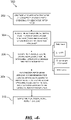
- the method 300 includes generating alternating current (AC) power with a generator of a power generation system, such as a wind turbine power system incorporating a DFIG as discussed above.
- the AC power may be a multiphase alternating current power, such as a three-phase alternating current power.
- the desired reactive power generation value required for production by the power converter at the changed generator rotor speed may be pre-defined based on known characteristics of the power generation system at the first switching frequency and/or the known load (grid) reactive power requirements and entered into the look-up table to determine the second switching frequency.
- the reactive power output of the power converter may be measured at the first switching frequency and used to enter the look-up table 216 to determine the second switching frequency that will be needed at the changed generator rotor speed.
Landscapes
- Engineering & Computer Science (AREA)
- Power Engineering (AREA)
- Life Sciences & Earth Sciences (AREA)
- Sustainable Development (AREA)
- Sustainable Energy (AREA)
- Chemical & Material Sciences (AREA)
- Combustion & Propulsion (AREA)
- Mechanical Engineering (AREA)
- General Engineering & Computer Science (AREA)
- Control Of Eletrric Generators (AREA)
Claims (15)
- Procédé (300) de fonctionnement d'un système de production de puissance (100) qui fournit une puissance réelle et réactive à une charge, comprenant :avec un convertisseur de puissance (162) ayant des éléments de commutation, recevoir (304) une puissance en courant alternatif à partir d'un générateur (120) et générer la puissance réactive dans une plage de fonctionnement de vitesse de rotor de générateur ;à mesure que la vitesse de rotor de générateur change et s'approche de la vitesse synchrone, générer (308) une commande de contrôle pour diminuer une fréquence de commutation des éléments de commutation d'une première fréquence de commutation à une seconde fréquence de commutation, dans lequel la sortie de puissance réactive du convertisseur de puissance (162) est augmentée à la seconde fréquence de commutation ; etdans lequel la seconde fréquence de commutation est déterminée en temps de fonctionnement réel du générateur (120) sur la base de la fourniture d'une valeur de puissance réactive définie à partir du convertisseur de puissance (162) à la vitesse de rotor de générateur modifiée à ou près de la vitesse synchrone et du maintien des éléments de commutation dans des limites thermiques définies.
- Procédé selon la revendication 1, dans lequel le convertisseur de puissance (162) comprend un convertisseur côté ligne, LSC (168), et un convertisseur côté rotor, RSC (166), le RSC (166) générant la puissance réactive.
- Procédé selon la revendication 2, dans lequel le générateur (120) est un générateur à induction à double alimentation, DFIG, dans un système de production de puissance à turbine éolienne (100).
- Procédé selon la revendication 2, dans lequel les éléments de commutation comprennent des éléments de transistor bipolaire à grille isolée, IGBT, (212, 214).
- Procédé selon l'une quelconque des revendications précédentes, dans lequel un contrôleur (174) détermine la seconde fréquence de commutation à partir d'une table de consultation qui renvoie à des valeurs de puissance réactive générées à la seconde fréquence de commutation à différentes vitesses de rotor de générateur.
- Procédé selon la revendication 5, dans lequel la table de consultation fournit les différentes vitesses de rotor de générateur sous la forme d'une pluralité de sous-plages et, pour chaque sous-plage, une seconde fréquence de commutation est fournie pour la valeur de puissance réactive.
- Procédé selon la revendication 6, dans lequel la table de consultation fournit une pluralité de valeurs de puissance réactive et une seconde fréquence de commutation correspondante pour chaque sous-plage à chacune des valeurs de puissance réactive.
- Procédé selon la revendication 5, dans lequel la valeur de puissance réactive requise du système de production de puissance (100) à une vitesse de rotor de générateur particulière est prédéfinie et entrée dans la table de consultation pour déterminer la seconde fréquence de commutation.
- Procédé selon la revendication 5, dans lequel la valeur de puissance réactive requise du système de production de puissance (100) à une vitesse de rotor de générateur particulière est mesurée en temps réel et entrée dans la table de consultation pour déterminer la seconde fréquence de commutation.
- Procédé selon l'une quelconque des revendications précédentes, dans lequel la seconde fréquence de commutation est déterminée de telle sorte que les distorsions harmoniques induites par le convertisseur de puissance (162) dans la charge soient comprises dans une valeur limite prédéfinie.
- Système de turbine éolienne (100) configuré pour fournir une puissance réelle et réactive à une charge, comprenant :un rotor de turbine éolienne (18) comprenant un moyeu (20) et une pluralité de pales (22) couplées au moyeu (20) ;un générateur à induction à double alimentation, DFIG (120), couplé au rotor de turbine éolienne (18) et pouvant fonctionner à une vitesse de rotor de générateur ;un convertisseur de puissance (162) configuré avec le DFIG (120) et comprenant un convertisseur côté ligne, LSC (168) et un convertisseur côté rotor, RSC (166), le RSC (166) comprenant une pluralité d'éléments de commutation configurés pour générer la puissance réactive ;un contrôleur (174) en communication avec le convertisseur de puissance (162) et, lorsque la vitesse de rotor de générateur change et s'approche de la vitesse synchrone, configuré pour générer une commande de contrôle pour diminuer une fréquence de commutation des éléments de commutation dans le RSC (166) d'une première fréquence de commutation à une seconde fréquence de commutation pour augmenter une sortie de la puissance réactive du RSC (166) ; etdans lequel la seconde fréquence de commutation est déterminée en temps de fonctionnement réel du générateur par le contrôleur (174) pour fournir une valeur de puissance réactive définie générée par le RSC (166) à une vitesse de rotor de générateur modifiée à ou près de la vitesse synchrone tout en maintenant les éléments de commutation dans des limites thermiques définies.
- Système de turbine éolienne (100) selon la revendication 11, dans lequel les éléments de commutation comprennent des éléments de transistor bipolaire à grille isolée, IGBT, (212, 214).
- Système de turbine éolienne (100) selon les revendications 11 et 12, dans lequel le contrôleur (174) détermine la seconde fréquence de commutation à partir d'une table de consultation qui renvoie à des valeurs de puissance réactive générées à la seconde fréquence de commutation à différentes vitesses de rotor de générateur.
- Système de turbine éolienne (100) selon la revendication 13, dans lequel la table de consultation comprend les différentes vitesses de rotor de générateur présentées sous la forme d'une pluralité de sous-plages et, pour chaque sous-plage, une seconde fréquence de commutation est fournie pour une valeur de puissance réactive particulière.
- Système de turbine éolienne (100) selon la revendication 14, dans lequel la table de consultation comprend une pluralité des valeurs de puissance réactive et de secondes fréquences de commutation correspondantes aux sous-plages de vitesses de rotor de générateur.
Applications Claiming Priority (1)
| Application Number | Priority Date | Filing Date | Title |
|---|---|---|---|
| US16/390,547 US10742149B1 (en) | 2019-04-22 | 2019-04-22 | System and method for reactive power control of a wind turbine by varying switching frequency of rotor side converter |
Publications (2)
| Publication Number | Publication Date |
|---|---|
| EP3731405A1 EP3731405A1 (fr) | 2020-10-28 |
| EP3731405B1 true EP3731405B1 (fr) | 2022-09-14 |
Family
ID=70292895
Family Applications (1)
| Application Number | Title | Priority Date | Filing Date |
|---|---|---|---|
| EP20169891.7A Active EP3731405B1 (fr) | 2019-04-22 | 2020-04-16 | Système et procédé de commande de la puissance réactive d'une éolienne par variation de la fréquence de commutation d'un convertisseur latéral de rotor |
Country Status (5)
| Country | Link |
|---|---|
| US (1) | US10742149B1 (fr) |
| EP (1) | EP3731405B1 (fr) |
| CN (1) | CN111828251B (fr) |
| DK (1) | DK3731405T3 (fr) |
| ES (1) | ES2933288T3 (fr) |
Families Citing this family (9)
| Publication number | Priority date | Publication date | Assignee | Title |
|---|---|---|---|---|
| JP2019146301A (ja) * | 2018-02-16 | 2019-08-29 | 本田技研工業株式会社 | インバータ発電機 |
| US11296612B2 (en) * | 2019-12-30 | 2022-04-05 | General Electric Company | Carrier-based pulse width modulation control for back-to-back voltage source converters |
| CN112145358B (zh) * | 2020-10-30 | 2021-07-23 | 上海电气风电集团股份有限公司 | 风力发电机组及其风向玫瑰图的校准方法 |
| EP3996228A1 (fr) * | 2020-11-04 | 2022-05-11 | Siemens Gamesa Renewable Energy Innovation & Technology S.L. | Contrôle du convertisseur réseau d'une machine asynchrone à double alimentation |
| CN113381588B (zh) * | 2021-06-09 | 2022-06-21 | 重庆大学 | 应用于igbt模块的热管理优化控制方法 |
| EP4117171A1 (fr) | 2021-07-06 | 2023-01-11 | Siemens Gamesa Renewable Energy Innovation & Technology S.L. | Procédé et appareil de commande mise en uvre par ordinateur d'une machine électrique à double alimentation |
| CN113992084B (zh) * | 2021-12-29 | 2022-04-01 | 苏州乾能电气有限公司 | 一种抑制发电机振动的方法、系统、装置及介质 |
| CN114396359B (zh) * | 2022-03-21 | 2025-09-23 | 上海电力大学 | 一种双馈风机变流器igbt热管理方法、系统和存储介质 |
| US12244244B2 (en) * | 2022-04-28 | 2025-03-04 | General Electric Renovables Espana, S.L. | Fault tolerant system and method for continuous skip-fire pulse width modulation for an active neutral point clamped converter |
Family Cites Families (69)
| Publication number | Priority date | Publication date | Assignee | Title |
|---|---|---|---|---|
| US904607A (en) | 1908-03-16 | 1908-11-24 | Hjalmar Elmblad | Seal-lock. |
| US5798631A (en) * | 1995-10-02 | 1998-08-25 | The State Of Oregon Acting By And Through The State Board Of Higher Education On Behalf Of Oregon State University | Performance optimization controller and control method for doubly-fed machines |
| WO2001091279A1 (fr) * | 2000-05-23 | 2001-11-29 | Vestas Wind Systems A/S | Eolienne a vitesse variable pourvue d'un convertisseur de matrice |
| US7071579B2 (en) | 2002-06-07 | 2006-07-04 | Global Energyconcepts,Llc | Wind farm electrical system |
| WO2004025803A1 (fr) | 2002-09-13 | 2004-03-25 | Abb Ab | Reseau alimente par energie eolienne |
| WO2004040748A1 (fr) * | 2002-11-01 | 2004-05-13 | Vestas Wind Systems A/S | Agencement de circuit pour systeme d'eolienne a vitesse variable comprenant une generateur d'induction a double alimentation et un convertisseur en opposition |
| JP2004208450A (ja) * | 2002-12-26 | 2004-07-22 | Sanden Corp | モータ制御装置 |
| US7095597B1 (en) | 2003-04-30 | 2006-08-22 | Clipper Windpower Technology, Inc. | Distributed static var compensation (DSVC) system for wind and water turbine applications |
| CA2518074C (fr) | 2003-05-02 | 2011-07-26 | Xantrex Technology Inc. | Systeme de commande de generateur d'induction a double alimentation |
| US6924565B2 (en) | 2003-08-18 | 2005-08-02 | General Electric Company | Continuous reactive power support for wind turbine generators |
| US7119452B2 (en) | 2003-09-03 | 2006-10-10 | General Electric Company | Voltage control for wind generators |
| US7013203B2 (en) | 2003-10-22 | 2006-03-14 | General Electric Company | Wind turbine system control |
| TW200530566A (en) * | 2004-03-05 | 2005-09-16 | Hitachi Ind Equipment Sys | Method for detecting temperature of semiconductor element and semiconductor power converter |
| US7356441B2 (en) * | 2005-09-28 | 2008-04-08 | Rockwell Automation Technologies, Inc. | Junction temperature prediction method and apparatus for use in a power conversion module |
| US7567160B2 (en) | 2006-02-15 | 2009-07-28 | American Superconductor Corporation | Supplementary transformer cooling in a reactive power compensation system |
| US7622815B2 (en) * | 2006-12-29 | 2009-11-24 | Ingeteam Energy, S.A. | Low voltage ride through system for a variable speed wind turbine having an exciter machine and a power converter not connected to the grid |
| JP5016967B2 (ja) * | 2007-04-20 | 2012-09-05 | 株式会社日立産機システム | 電力変換装置及びパワーサイクル寿命予測方法 |
| US7847526B2 (en) * | 2007-09-28 | 2010-12-07 | General Electric Company | System and method for controlling torque ripples in synchronous machines |
| US7884492B2 (en) * | 2007-11-13 | 2011-02-08 | General Electric Company | Methods and systems for wind turbine generators |
| CN201167296Y (zh) | 2007-12-14 | 2008-12-17 | 张勇 | 直驱式交流励磁风力发电机系统 |
| DE102008003299B4 (de) * | 2008-01-07 | 2016-06-09 | Woodward Kempen Gmbh | Verfahren zum Betreiben einer Windenergieanlage |
| US8242735B2 (en) * | 2008-07-09 | 2012-08-14 | Caterpillar Inc. | Method and system for temperature-based power converter control |
| US8188610B2 (en) * | 2008-09-08 | 2012-05-29 | General Electric Company | Wind turbine having a main power converter and an auxiliary power converter and a method for the control thereof |
| US8148929B2 (en) | 2008-09-30 | 2012-04-03 | Rockwell Automation Technologies, Inc. | Power electronic module IGBT protection method and system |
| WO2010079235A2 (fr) * | 2009-01-12 | 2010-07-15 | Vestas Wind Systems A/S | Fréquence de commutation d'un convertisseur fonction de la charge |
| US8360636B2 (en) * | 2009-07-02 | 2013-01-29 | Renesas Electronics America Inc. | Temperature detection and reporting system and method in power driving and/or consuming system |
| WO2011012733A1 (fr) | 2009-07-27 | 2011-02-03 | Gamesa Innovation & Technology, S.L. | Système pour la compensation d'énergie réactive dans un système d'énergie électrique |
| US7923862B2 (en) | 2009-10-06 | 2011-04-12 | General Electric Company | Reactive power regulation and voltage support for renewable energy plants |
| US8046109B2 (en) | 2009-12-16 | 2011-10-25 | General Electric Company | Method and systems for operating a wind turbine |
| US9236742B2 (en) | 2010-02-25 | 2016-01-12 | Vestas Wind Systems A/S | Method and control arrangement for controlling a reactive power source |
| US8471516B2 (en) | 2010-05-24 | 2013-06-25 | Rockwell Automation Technologies, Inc. | Adjustable speed drive lifetime improvement method |
| US8432052B2 (en) * | 2010-05-27 | 2013-04-30 | Rockwell Automation Technologies, Inc. | Wind power converter system with grid side reactive power control |
| AU2011260701B2 (en) | 2010-06-03 | 2015-08-20 | Vestas Wind Systems A/S | Method and control arrangement for controlling central capacitors in wind power plants |
| US8736091B2 (en) * | 2010-06-18 | 2014-05-27 | Rockwell Automation Technologies, Inc. | Converter lifetime improvement method for doubly fed induction generator |
| WO2011161692A2 (fr) | 2010-06-21 | 2011-12-29 | Raghunathan V R | Gestion de puissance réactive pour applications d'éolienne |
| US8664800B2 (en) | 2010-08-31 | 2014-03-04 | General Electric Company | System and method for distribution of inverter VAR support |
| JP5549505B2 (ja) * | 2010-09-28 | 2014-07-16 | 日産自動車株式会社 | 温度保護装置、モータ制御装置及び温度保護方法 |
| US8093741B2 (en) * | 2010-10-29 | 2012-01-10 | General Electric Company | Method and system for providing increased turbine output for doubly fed induction generator |
| EP2503146B1 (fr) | 2011-03-21 | 2013-12-18 | Siemens Aktiengesellschaft | Procédé et agencement de contrôle du fonctionnement d'une installation de production d'énergie électrique durant une déconnexion de grille utilitaire. |
| CN102810875B (zh) * | 2011-05-30 | 2014-10-22 | 通用电气公司 | 使用变流器进行能量转换的系统及其运作方法 |
| US9368971B2 (en) | 2011-06-23 | 2016-06-14 | Inventus Holdings, Llc | Multiple renewables site electrical generation and reactive power control |
| JP5578197B2 (ja) * | 2012-06-01 | 2014-08-27 | 株式会社デンソー | 温度検出装置 |
| RU2581612C1 (ru) * | 2012-08-03 | 2016-04-20 | Абб Текнолоджи Аг | Ограничение перегрузки при работе с пиковой мощностью |
| JP5930911B2 (ja) * | 2012-08-08 | 2016-06-08 | 株式会社日立製作所 | 電力変換装置 |
| CN104641529B (zh) | 2012-09-17 | 2018-09-18 | 维斯塔斯风力系统集团公司 | 用于确定发电设备控制器中的个体设定点的方法和发电设备控制器 |
| IN2015DN02395A (fr) | 2012-09-17 | 2015-09-04 | Vestas Wind Sys As | |
| CN102882229B (zh) | 2012-09-21 | 2015-06-17 | 北京金风科创风电设备有限公司 | 风电场动态电压自动控制系统 |
| EP2741392A3 (fr) | 2012-12-04 | 2016-12-14 | ABB Research Ltd. | Systèmes et procédés permettant d'utiliser un compensateur actif pour augmenter un redresseur à diodes |
| US9680307B2 (en) | 2012-12-21 | 2017-06-13 | General Electric Company | System and method for voltage regulation of a renewable energy plant |
| EP2957012B1 (fr) | 2013-02-15 | 2017-05-03 | Vestas Wind Systems A/S | Procédé de fonctionnement d'une centrale éolienne |
| US8853876B1 (en) | 2013-04-26 | 2014-10-07 | General Electric Company | Switching-based control for a power converter |
| US9083260B2 (en) | 2013-05-21 | 2015-07-14 | Control Techniques Limited | Inverter controller and method of controlling an inverter |
| US8975768B2 (en) * | 2013-06-05 | 2015-03-10 | General Electic Company | Methods for operating wind turbine system having dynamic brake |
| EP3075054B1 (fr) | 2013-11-28 | 2019-01-09 | Vestas Wind Systems A/S | Reconfiguration de la boucle de puissance réactive d'une centrale éolienne |
| JP5907236B2 (ja) * | 2013-12-11 | 2016-04-26 | 株式会社デンソー | 温度検出装置 |
| US9419439B2 (en) | 2014-01-14 | 2016-08-16 | Siemens Aktiengesellschaft | Reconnecting a wind power plant to a utility grid |
| US9780710B2 (en) | 2014-04-15 | 2017-10-03 | General Electric Company | Reactive power control for wind turbine generators |
| US9447772B2 (en) * | 2014-12-18 | 2016-09-20 | General Electric Company | Systems and methods for increasing wind turbine power output |
| US9831810B2 (en) | 2015-03-10 | 2017-11-28 | General Electric Company | System and method for improved reactive power speed-of-response for a wind farm |
| CN104795835B (zh) * | 2015-03-26 | 2017-02-01 | 同济大学 | 一种双馈风电变流器开关频率的控制方法及系统 |
| US9625921B2 (en) | 2015-04-03 | 2017-04-18 | Ge Energy Power Conversion Technology Ltd | Life of a semiconductor by reducing temperature changes therein via switching frequency |
| US10496052B2 (en) * | 2015-04-10 | 2019-12-03 | The Board Of Trustees Of The University Of Alabama | Systems, methods and devices for vector control of induction machines using artificial neural networks |
| US10107260B2 (en) | 2015-11-19 | 2018-10-23 | General Electric Company | Wind turbine auxiliary circuit control |
| AU2017362883B2 (en) * | 2016-11-17 | 2022-03-03 | General Electric Company | Method and system for operating a hybrid power generation system |
| US10103663B1 (en) * | 2017-04-18 | 2018-10-16 | General Electric Company | Control method for protecting switching devices in power converters in doubly fed induction generator power systems |
| WO2018200178A1 (fr) * | 2017-04-28 | 2018-11-01 | General Electric Company | Procédé et système pour améliorer la production d'énergie électrique par un système de production d'énergie |
| US10707789B2 (en) * | 2017-05-12 | 2020-07-07 | General Electric Company | Adaptive current damping module for improved power converter control in wind turbine systems |
| US10731630B2 (en) * | 2018-01-03 | 2020-08-04 | General Electric Company | Extended reaction power for wind farms |
| US10615727B2 (en) * | 2018-08-27 | 2020-04-07 | General Electric Company | Dynamic brake circuit assembly for a wind turbine |
-
2019
- 2019-04-22 US US16/390,547 patent/US10742149B1/en active Active
-
2020
- 2020-04-16 DK DK20169891.7T patent/DK3731405T3/da active
- 2020-04-16 EP EP20169891.7A patent/EP3731405B1/fr active Active
- 2020-04-16 ES ES20169891T patent/ES2933288T3/es active Active
- 2020-04-22 CN CN202010321848.XA patent/CN111828251B/zh active Active
Also Published As
| Publication number | Publication date |
|---|---|
| US10742149B1 (en) | 2020-08-11 |
| CN111828251B (zh) | 2025-02-18 |
| ES2933288T3 (es) | 2023-02-03 |
| DK3731405T3 (da) | 2022-11-21 |
| EP3731405A1 (fr) | 2020-10-28 |
| CN111828251A (zh) | 2020-10-27 |
Similar Documents
| Publication | Publication Date | Title |
|---|---|---|
| US10742149B1 (en) | System and method for reactive power control of a wind turbine by varying switching frequency of rotor side converter | |
| EP3745553B1 (fr) | Système et procédé pour faire fonctionner un parc éolien en cas de vents faibles | |
| EP3736939B1 (fr) | Système et méthode pour controller la puissance réactive d'une éolienne dans un champ d'éoliennes ayant un compensateur de puissance réactive statique | |
| US8853876B1 (en) | Switching-based control for a power converter | |
| US11296612B2 (en) | Carrier-based pulse width modulation control for back-to-back voltage source converters | |
| EP3736935B1 (fr) | Système d'éolienne doté d'un dispositif de compensation de puissance réactive intégré | |
| US12009770B2 (en) | System and method for providing grid-forming control of an inverter-based resource | |
| US11486360B2 (en) | System and method for controlling wind turbine converters during high voltage ride through events | |
| US11196260B2 (en) | System and method for control of reactive power from a reactive power compensation device in a wind turbine system | |
| EP4024695A1 (fr) | Procédé pour faire fonctionner un aérogénérateur à double alimentation en tant que machine synchrone virtuelle afin de fournir une commande de formation de réseau pour celui-ci | |
| CA3139584A1 (fr) | Systeme et methode pour exploiter une ressource a base d'inverseur asynchrone comme synchromachine virtuelle pour fournir un controle de formation de grille | |
| WO2024118066A1 (fr) | Système et procédé pour faire fonctionner une ressource fondée sur des onduleurs dans un mode de formation de réseau (gfm) pour une stabilité améliorée | |
| EP3736940B1 (fr) | Système et procédé pour la commande coordonnée de la puissance réactive d'un générateur et d'un dispositif de compensation de la puissance réactive dans un système d'éolienne | |
| US10218298B2 (en) | Spillover of reactive current to line side converter | |
| EP4609500A1 (fr) | Système et procédé d'extension du seuil de vitesse de fonctionnement d'une ressource à base d'onduleur formant un réseau | |
| US10958200B1 (en) | System and method for operating a wind turbine power system during low wind speeds to improve efficiency | |
| WO2025141303A1 (fr) | Système et procédé pour assurer un démarrage à froid de ressources basées sur un onduleur formant un réseau | |
| WO2025085048A1 (fr) | Système et procédé de fonctionnement d'une ressource basée sur un onduleur dans de multiples modes de fonctionnement | |
| WO2025078856A1 (fr) | Système et procédé pour assurer un démarrage à froid de ressources basées sur un onduleur formant un réseau | |
| WO2025155283A1 (fr) | Système et procédé pour réaliser un démarrage autonome de ressources basées sur un onduleur formant un réseau | |
| WO2026080070A1 (fr) | Système et procédé de régulation de flux sur des circuits auxiliaires dans une ressource basée sur un onduleur |
Legal Events
| Date | Code | Title | Description |
|---|---|---|---|
| PUAI | Public reference made under article 153(3) epc to a published international application that has entered the european phase |
Free format text: ORIGINAL CODE: 0009012 |
|
| STAA | Information on the status of an ep patent application or granted ep patent |
Free format text: STATUS: THE APPLICATION HAS BEEN PUBLISHED |
|
| AK | Designated contracting states |
Kind code of ref document: A1 Designated state(s): AL AT BE BG CH CY CZ DE DK EE ES FI FR GB GR HR HU IE IS IT LI LT LU LV MC MK MT NL NO PL PT RO RS SE SI SK SM TR |
|
| AX | Request for extension of the european patent |
Extension state: BA ME |
|
| STAA | Information on the status of an ep patent application or granted ep patent |
Free format text: STATUS: REQUEST FOR EXAMINATION WAS MADE |
|
| 17P | Request for examination filed |
Effective date: 20210420 |
|
| RBV | Designated contracting states (corrected) |
Designated state(s): AL AT BE BG CH CY CZ DE DK EE ES FI FR GB GR HR HU IE IS IT LI LT LU LV MC MK MT NL NO PL PT RO RS SE SI SK SM TR |
|
| GRAP | Despatch of communication of intention to grant a patent |
Free format text: ORIGINAL CODE: EPIDOSNIGR1 |
|
| STAA | Information on the status of an ep patent application or granted ep patent |
Free format text: STATUS: GRANT OF PATENT IS INTENDED |
|
| RIC1 | Information provided on ipc code assigned before grant |
Ipc: H02P 9/00 20060101AFI20220308BHEP |
|
| INTG | Intention to grant announced |
Effective date: 20220405 |
|
| GRAS | Grant fee paid |
Free format text: ORIGINAL CODE: EPIDOSNIGR3 |
|
| GRAA | (expected) grant |
Free format text: ORIGINAL CODE: 0009210 |
|
| STAA | Information on the status of an ep patent application or granted ep patent |
Free format text: STATUS: THE PATENT HAS BEEN GRANTED |
|
| AK | Designated contracting states |
Kind code of ref document: B1 Designated state(s): AL AT BE BG CH CY CZ DE DK EE ES FI FR GB GR HR HU IE IS IT LI LT LU LV MC MK MT NL NO PL PT RO RS SE SI SK SM TR |
|
| REG | Reference to a national code |
Ref country code: GB Ref legal event code: FG4D |
|
| REG | Reference to a national code |
Ref country code: CH Ref legal event code: EP |
|
| REG | Reference to a national code |
Ref country code: DE Ref legal event code: R096 Ref document number: 602020005074 Country of ref document: DE |
|
| REG | Reference to a national code |
Ref country code: IE Ref legal event code: FG4D |
|
| REG | Reference to a national code |
Ref country code: AT Ref legal event code: REF Ref document number: 1519312 Country of ref document: AT Kind code of ref document: T Effective date: 20221015 |
|
| REG | Reference to a national code |
Ref country code: DK Ref legal event code: T3 Effective date: 20221116 |
|
| REG | Reference to a national code |
Ref country code: LT Ref legal event code: MG9D |
|
| REG | Reference to a national code |
Ref country code: NL Ref legal event code: MP Effective date: 20220914 |
|
| PG25 | Lapsed in a contracting state [announced via postgrant information from national office to epo] |
Ref country code: SE Free format text: LAPSE BECAUSE OF FAILURE TO SUBMIT A TRANSLATION OF THE DESCRIPTION OR TO PAY THE FEE WITHIN THE PRESCRIBED TIME-LIMIT Effective date: 20220914 Ref country code: RS Free format text: LAPSE BECAUSE OF FAILURE TO SUBMIT A TRANSLATION OF THE DESCRIPTION OR TO PAY THE FEE WITHIN THE PRESCRIBED TIME-LIMIT Effective date: 20220914 Ref country code: NO Free format text: LAPSE BECAUSE OF FAILURE TO SUBMIT A TRANSLATION OF THE DESCRIPTION OR TO PAY THE FEE WITHIN THE PRESCRIBED TIME-LIMIT Effective date: 20221214 Ref country code: LV Free format text: LAPSE BECAUSE OF FAILURE TO SUBMIT A TRANSLATION OF THE DESCRIPTION OR TO PAY THE FEE WITHIN THE PRESCRIBED TIME-LIMIT Effective date: 20220914 Ref country code: LT Free format text: LAPSE BECAUSE OF FAILURE TO SUBMIT A TRANSLATION OF THE DESCRIPTION OR TO PAY THE FEE WITHIN THE PRESCRIBED TIME-LIMIT Effective date: 20220914 Ref country code: FI Free format text: LAPSE BECAUSE OF FAILURE TO SUBMIT A TRANSLATION OF THE DESCRIPTION OR TO PAY THE FEE WITHIN THE PRESCRIBED TIME-LIMIT Effective date: 20220914 |
|
| REG | Reference to a national code |
Ref country code: ES Ref legal event code: FG2A Ref document number: 2933288 Country of ref document: ES Kind code of ref document: T3 Effective date: 20230203 |
|
| REG | Reference to a national code |
Ref country code: AT Ref legal event code: MK05 Ref document number: 1519312 Country of ref document: AT Kind code of ref document: T Effective date: 20220914 |
|
| PG25 | Lapsed in a contracting state [announced via postgrant information from national office to epo] |
Ref country code: HR Free format text: LAPSE BECAUSE OF FAILURE TO SUBMIT A TRANSLATION OF THE DESCRIPTION OR TO PAY THE FEE WITHIN THE PRESCRIBED TIME-LIMIT Effective date: 20220914 Ref country code: GR Free format text: LAPSE BECAUSE OF FAILURE TO SUBMIT A TRANSLATION OF THE DESCRIPTION OR TO PAY THE FEE WITHIN THE PRESCRIBED TIME-LIMIT Effective date: 20221215 |
|
| PG25 | Lapsed in a contracting state [announced via postgrant information from national office to epo] |
Ref country code: SM Free format text: LAPSE BECAUSE OF FAILURE TO SUBMIT A TRANSLATION OF THE DESCRIPTION OR TO PAY THE FEE WITHIN THE PRESCRIBED TIME-LIMIT Effective date: 20220914 Ref country code: RO Free format text: LAPSE BECAUSE OF FAILURE TO SUBMIT A TRANSLATION OF THE DESCRIPTION OR TO PAY THE FEE WITHIN THE PRESCRIBED TIME-LIMIT Effective date: 20220914 Ref country code: PT Free format text: LAPSE BECAUSE OF FAILURE TO SUBMIT A TRANSLATION OF THE DESCRIPTION OR TO PAY THE FEE WITHIN THE PRESCRIBED TIME-LIMIT Effective date: 20230116 Ref country code: CZ Free format text: LAPSE BECAUSE OF FAILURE TO SUBMIT A TRANSLATION OF THE DESCRIPTION OR TO PAY THE FEE WITHIN THE PRESCRIBED TIME-LIMIT Effective date: 20220914 Ref country code: AT Free format text: LAPSE BECAUSE OF FAILURE TO SUBMIT A TRANSLATION OF THE DESCRIPTION OR TO PAY THE FEE WITHIN THE PRESCRIBED TIME-LIMIT Effective date: 20220914 |
|
| PG25 | Lapsed in a contracting state [announced via postgrant information from national office to epo] |
Ref country code: SK Free format text: LAPSE BECAUSE OF FAILURE TO SUBMIT A TRANSLATION OF THE DESCRIPTION OR TO PAY THE FEE WITHIN THE PRESCRIBED TIME-LIMIT Effective date: 20220914 Ref country code: PL Free format text: LAPSE BECAUSE OF FAILURE TO SUBMIT A TRANSLATION OF THE DESCRIPTION OR TO PAY THE FEE WITHIN THE PRESCRIBED TIME-LIMIT Effective date: 20220914 Ref country code: IS Free format text: LAPSE BECAUSE OF FAILURE TO SUBMIT A TRANSLATION OF THE DESCRIPTION OR TO PAY THE FEE WITHIN THE PRESCRIBED TIME-LIMIT Effective date: 20230114 Ref country code: EE Free format text: LAPSE BECAUSE OF FAILURE TO SUBMIT A TRANSLATION OF THE DESCRIPTION OR TO PAY THE FEE WITHIN THE PRESCRIBED TIME-LIMIT Effective date: 20220914 |
|
| REG | Reference to a national code |
Ref country code: DE Ref legal event code: R097 Ref document number: 602020005074 Country of ref document: DE |
|
| PG25 | Lapsed in a contracting state [announced via postgrant information from national office to epo] |
Ref country code: NL Free format text: LAPSE BECAUSE OF FAILURE TO SUBMIT A TRANSLATION OF THE DESCRIPTION OR TO PAY THE FEE WITHIN THE PRESCRIBED TIME-LIMIT Effective date: 20220914 Ref country code: AL Free format text: LAPSE BECAUSE OF FAILURE TO SUBMIT A TRANSLATION OF THE DESCRIPTION OR TO PAY THE FEE WITHIN THE PRESCRIBED TIME-LIMIT Effective date: 20220914 |
|
| P01 | Opt-out of the competence of the unified patent court (upc) registered |
Effective date: 20230530 |
|
| PLBE | No opposition filed within time limit |
Free format text: ORIGINAL CODE: 0009261 |
|
| STAA | Information on the status of an ep patent application or granted ep patent |
Free format text: STATUS: NO OPPOSITION FILED WITHIN TIME LIMIT |
|
| 26N | No opposition filed |
Effective date: 20230615 |
|
| PG25 | Lapsed in a contracting state [announced via postgrant information from national office to epo] |
Ref country code: SI Free format text: LAPSE BECAUSE OF FAILURE TO SUBMIT A TRANSLATION OF THE DESCRIPTION OR TO PAY THE FEE WITHIN THE PRESCRIBED TIME-LIMIT Effective date: 20220914 |
|
| REG | Reference to a national code |
Ref country code: CH Ref legal event code: PL |
|
| REG | Reference to a national code |
Ref country code: DE Ref legal event code: R081 Ref document number: 602020005074 Country of ref document: DE Owner name: GENERAL ELECTRIC RENOVABLES ESPANA, S.L., ES Free format text: FORMER OWNER: GENERAL ELECTRIC COMPANY, SCHENECTADY, NY, US Ref country code: DE Ref document number: 602020005074 Country of ref document: DE Ref country code: DE Ref legal event code: R082 Ref document number: 602020005074 Country of ref document: DE Representative=s name: ZIMMERMANN & PARTNER PATENTANWAELTE MBB, DE |
|
| PG25 | Lapsed in a contracting state [announced via postgrant information from national office to epo] |
Ref country code: LU Free format text: LAPSE BECAUSE OF NON-PAYMENT OF DUE FEES Effective date: 20230416 |
|
| REG | Reference to a national code |
Ref country code: BE Ref legal event code: MM Effective date: 20230430 |
|
| PG25 | Lapsed in a contracting state [announced via postgrant information from national office to epo] |
Ref country code: MC Free format text: LAPSE BECAUSE OF FAILURE TO SUBMIT A TRANSLATION OF THE DESCRIPTION OR TO PAY THE FEE WITHIN THE PRESCRIBED TIME-LIMIT Effective date: 20220914 |
|
| PG25 | Lapsed in a contracting state [announced via postgrant information from national office to epo] |
Ref country code: MC Free format text: LAPSE BECAUSE OF FAILURE TO SUBMIT A TRANSLATION OF THE DESCRIPTION OR TO PAY THE FEE WITHIN THE PRESCRIBED TIME-LIMIT Effective date: 20220914 Ref country code: LI Free format text: LAPSE BECAUSE OF NON-PAYMENT OF DUE FEES Effective date: 20230430 Ref country code: FR Free format text: LAPSE BECAUSE OF NON-PAYMENT OF DUE FEES Effective date: 20230430 Ref country code: CH Free format text: LAPSE BECAUSE OF NON-PAYMENT OF DUE FEES Effective date: 20230430 |
|
| REG | Reference to a national code |
Ref country code: IE Ref legal event code: MM4A |
|
| PG25 | Lapsed in a contracting state [announced via postgrant information from national office to epo] |
Ref country code: BE Free format text: LAPSE BECAUSE OF NON-PAYMENT OF DUE FEES Effective date: 20230430 |
|
| REG | Reference to a national code |
Ref country code: DE Ref legal event code: R082 Ref document number: 602020005074 Country of ref document: DE Representative=s name: ZIMMERMANN & PARTNER PATENTANWAELTE MBB, DE |
|
| PG25 | Lapsed in a contracting state [announced via postgrant information from national office to epo] |
Ref country code: IE Free format text: LAPSE BECAUSE OF NON-PAYMENT OF DUE FEES Effective date: 20230416 |
|
| PG25 | Lapsed in a contracting state [announced via postgrant information from national office to epo] |
Ref country code: IE Free format text: LAPSE BECAUSE OF NON-PAYMENT OF DUE FEES Effective date: 20230416 |
|
| PG25 | Lapsed in a contracting state [announced via postgrant information from national office to epo] |
Ref country code: IT Free format text: LAPSE BECAUSE OF FAILURE TO SUBMIT A TRANSLATION OF THE DESCRIPTION OR TO PAY THE FEE WITHIN THE PRESCRIBED TIME-LIMIT Effective date: 20220914 |
|
| REG | Reference to a national code |
Ref country code: ES Ref legal event code: PC2A Owner name: GENERAL ELECTRIC RENOVABLES ESPANA S.L. Effective date: 20240809 |
|
| PG25 | Lapsed in a contracting state [announced via postgrant information from national office to epo] |
Ref country code: BG Free format text: LAPSE BECAUSE OF FAILURE TO SUBMIT A TRANSLATION OF THE DESCRIPTION OR TO PAY THE FEE WITHIN THE PRESCRIBED TIME-LIMIT Effective date: 20220914 |
|
| PG25 | Lapsed in a contracting state [announced via postgrant information from national office to epo] |
Ref country code: BG Free format text: LAPSE BECAUSE OF FAILURE TO SUBMIT A TRANSLATION OF THE DESCRIPTION OR TO PAY THE FEE WITHIN THE PRESCRIBED TIME-LIMIT Effective date: 20220914 |
|
| GBPC | Gb: european patent ceased through non-payment of renewal fee |
Effective date: 20240416 |
|
| PG25 | Lapsed in a contracting state [announced via postgrant information from national office to epo] |
Ref country code: GB Free format text: LAPSE BECAUSE OF NON-PAYMENT OF DUE FEES Effective date: 20240416 |
|
| PG25 | Lapsed in a contracting state [announced via postgrant information from national office to epo] |
Ref country code: GB Free format text: LAPSE BECAUSE OF NON-PAYMENT OF DUE FEES Effective date: 20240416 |
|
| PG25 | Lapsed in a contracting state [announced via postgrant information from national office to epo] |
Ref country code: CY Free format text: LAPSE BECAUSE OF FAILURE TO SUBMIT A TRANSLATION OF THE DESCRIPTION OR TO PAY THE FEE WITHIN THE PRESCRIBED TIME-LIMIT; INVALID AB INITIO Effective date: 20200416 |
|
| PG25 | Lapsed in a contracting state [announced via postgrant information from national office to epo] |
Ref country code: HU Free format text: LAPSE BECAUSE OF FAILURE TO SUBMIT A TRANSLATION OF THE DESCRIPTION OR TO PAY THE FEE WITHIN THE PRESCRIBED TIME-LIMIT; INVALID AB INITIO Effective date: 20200416 |
|
| PG25 | Lapsed in a contracting state [announced via postgrant information from national office to epo] |
Ref country code: TR Free format text: LAPSE BECAUSE OF FAILURE TO SUBMIT A TRANSLATION OF THE DESCRIPTION OR TO PAY THE FEE WITHIN THE PRESCRIBED TIME-LIMIT Effective date: 20220914 |
|
| PGFP | Annual fee paid to national office [announced via postgrant information from national office to epo] |
Ref country code: DK Payment date: 20260319 Year of fee payment: 7 |
|
| PGFP | Annual fee paid to national office [announced via postgrant information from national office to epo] |
Ref country code: ES Payment date: 20260504 Year of fee payment: 7 |
|
| PGFP | Annual fee paid to national office [announced via postgrant information from national office to epo] |
Ref country code: DE Payment date: 20260319 Year of fee payment: 7 |