EP3731438A1 - Datenkommunikationsvorrichtung - Google Patents
Datenkommunikationsvorrichtung Download PDFInfo
- Publication number
- EP3731438A1 EP3731438A1 EP18891979.9A EP18891979A EP3731438A1 EP 3731438 A1 EP3731438 A1 EP 3731438A1 EP 18891979 A EP18891979 A EP 18891979A EP 3731438 A1 EP3731438 A1 EP 3731438A1
- Authority
- EP
- European Patent Office
- Prior art keywords
- belt
- communication device
- data communication
- buckle
- electrode
- Prior art date
- Legal status (The legal status is an assumption and is not a legal conclusion. Google has not performed a legal analysis and makes no representation as to the accuracy of the status listed.)
- Withdrawn
Links
Images


Classifications
-
- H—ELECTRICITY
- H04—ELECTRIC COMMUNICATION TECHNIQUE
- H04B—TRANSMISSION
- H04B13/00—Transmission systems characterised by the medium used for transmission, not provided for in groups H04B3/00 - H04B11/00
- H04B13/005—Transmission systems in which the medium consists of the human body
-
- A—HUMAN NECESSITIES
- A61—MEDICAL OR VETERINARY SCIENCE; HYGIENE
- A61B—DIAGNOSIS; SURGERY; IDENTIFICATION
- A61B5/00—Measuring for diagnostic purposes; Identification of persons
- A61B5/0002—Remote monitoring of patients using telemetry, e.g. transmission of vital signals via a communication network
- A61B5/0026—Remote monitoring of patients using telemetry, e.g. transmission of vital signals via a communication network characterised by the transmission medium
- A61B5/0028—Body tissue as transmission medium, i.e. transmission systems where the medium is the human body
-
- H—ELECTRICITY
- H01—ELECTRIC ELEMENTS
- H01T—SPARK GAPS; OVERVOLTAGE ARRESTERS USING SPARK GAPS; SPARKING PLUGS; CORONA DEVICES; GENERATING IONS TO BE INTRODUCED INTO NON-ENCLOSED GASES
- H01T13/00—Sparking plugs
- H01T13/20—Sparking plugs characterised by features of the electrodes or insulation
- H01T13/32—Sparking plugs characterised by features of the electrodes or insulation characterised by features of the earthed electrode
-
- H—ELECTRICITY
- H04—ELECTRIC COMMUNICATION TECHNIQUE
- H04B—TRANSMISSION
- H04B5/00—Near-field transmission systems, e.g. inductive or capacitive transmission systems
- H04B5/20—Near-field transmission systems, e.g. inductive or capacitive transmission systems characterised by the transmission technique; characterised by the transmission medium
- H04B5/22—Capacitive coupling
-
- H—ELECTRICITY
- H04—ELECTRIC COMMUNICATION TECHNIQUE
- H04W—WIRELESS COMMUNICATION NETWORKS
- H04W4/00—Services specially adapted for wireless communication networks; Facilities therefor
- H04W4/80—Services using short range communication, e.g. near-field communication [NFC], radio-frequency identification [RFID] or low energy communication
Definitions
- the present disclosure relates to a wearable data communication device that is fitted to a part of a human body when used.
- the conventional wearable data communication device includes a body case, a communication unit, a communication electrode, a ground electrode, a belt, and a buckle.
- the communication unit is housed in the body case.
- the communication electrode comes into contact with a human body and transmits and receives communication signals.
- the belt is joined to the body case.
- the ground electrode is formed at a leading portion of the belt. A connection between the ground electrode and the communication unit and a connection between the communication electrode and the communication unit are made by, for example, wires routed inside the belt.
- the belt When such a data communication device is put on the human body, the belt is worn around a human body part such as an arm. The belt is fastened with the buckle and thus is kept attached to the human body.
- the buckle Provided near a leading edge of the belt are a plurality of pin holes.
- the buckle includes a metal ring and a pin. The pin spans the ring.
- the data communication device communicates with a communication control device via the human body when the communication control device is touched by, for example, a finger or a palm.
- the communication electrode and the ground electrode both touch the human body.
- the communication electrode and the ground electrode are both disposed on the same side as the case's surface of contact with the human body.
- PTLs 1 and 2 are known examples of prior art literature on a wearable data communication device such as described above as being relevant to the present disclosure.
- the belt length adjustment is restricted by pin hole position. Therefore, the belt may not be adjusted to a length that allows the communication electrode to touch skin of a wearer.
- a belt portion to be joined to a buckle can be cut off so that belt has an adjusted length.
- a belt portion cannot be cut off for an adjusted length. Consequently, a great clearance may problematically be caused between the communication electrode and the human body, depending on the wearer.
- the communication electrode and the ground electrode of the above-described conventional data communication device are both disposed on the side that the case touches the human body, there is a close distance between the communication electrode and the ground electrode. Accordingly, signals output from a transmission electrode or signals to be received by the transmission electrode flow toward the ground electrode, thus problematically causing poor communication sensitivity between the data communication device and the communication control device.
- the present disclosure overcomes these problems, and an object of the present disclosure is to provide a data communication device that enables a reduced clearance between a communication electrode and a human body and can have stable communication quality together with satisfactory communication sensitivity between the data communication device and a communication control device.
- a data communication device includes a fitting surface and an outer surface.
- the outer surface is positioned opposite the fitting surface.
- the data communication device also includes a buckle, a belt, a communication electrode, and a communication unit.
- the belt is joined to the buckle.
- the communication electrode is formed at the belt or the buckle to be exposed at the fitting surface.
- the communication unit is electrically connected to the communication electrode.
- the buckle includes a buckle mechanism. The above structure can achieve the intended object.
- a data communication device includes a body, a belt, a power source, a communication unit, a communication electrode, and a ground electrode of plate shape.
- the body case includes a bottom face and a side face.
- the belt is joined to the body case at the side face of the body case.
- the power source is housed in the body case.
- the communication unit is driven by the power source.
- the communication electrode is connected to the communication unit and is exposed at the bottom face of the body case.
- the ground electrode is connected to a ground of the communication unit inside the body.
- the belt at least partly includes an insulator.
- the ground electrode includes a second surface that extends out of the body case to face a first plane extending, as an extension of a surface of the communication electrode, beyond the body case. The second surface is covered by the insulator.
- the buckle of the present disclosure has the buckle mechanism, so that length of the belt can be adjusted freely. Because the belt can be set to have a length that is right for a wearer, a reduced clearance can be achieved between the communication electrode and a human body when the wearer puts on the data communication device. As a result, the data communication device provided can have stable communication quality.
- the insulator can prevent the ground electrode from directly touching the human body when the data communication device according to the present disclosure is fitted to the human body. Therefore, signals output from a transmission electrode or signals to be received by the transmission electrode do not easily flow toward the ground electrode. Consequently, improved communication sensitivity is achieved between the data communication device and a communication control device.
- FIG. 1 is a conceptual diagram of data communication system 1001.
- Data communication system 1001 includes data communication device 11 and communication control device 1002.
- Communication control device 1002 includes communication electrode 1002a, ground electrode 1002b, and communication unit 1002c.
- Communication electrode 1002a is connected to communication unit 1002c.
- Ground electrode 1002b and a ground terminal (not illustrated) of communication unit 1002c are both connected to ground 1003.
- Data communication device 11 is put on wearer's arm 1004a, for example.
- FIG. 3 is a conceptual diagram of data communication device 11. As illustrated in FIG. 3 , data communication device 11 includes fitting surface 11a and outer surface 11b. Outer surface 11b is positioned opposite fitting surface 11a. Data communication device 11 is put on arm 1004a with fitting surface 11a facing arm 1004a. In this case, wearer 1004 touches communication electrode 1002a with hand 1004c. Thus communication is established between data communication device 11 and communication control device 1002. The communication between data communication device 11 and communication control device 1002 is established via a body of wearer 1004.
- wearer 1004 only has to touch communication electrode 1002a with a palm, a back of the hand, or finger 1004b.
- wearer 1004 may use, for example, arm 1004a, specifically an elbow, so that the part of hand 1004c is not limiting.
- wearer 1004 touches communication electrode 1002a with the body part close to where data communication device 11 is put on.
- something may be interposed between finger 1004b and communication electrode 1002a as long as communication is possible, so that direct touching of communication electrode 1002a by wearer 1004 is not limiting.
- data communication device 11 Since data communication device 11 is put on wearer 1004 as described above, data communication device 11 cannot be connected directly to a ground or the like by a ground wire, for example. Therefore, data communication device 11 is generally ungrounded when operating. In other words, data communication device 11 is put in a floating state in terms of potential. Data communication device 11 may be put on a body part such as a leg or a trunk, so that arm 1004a is not limiting.
- Wearer 1004 generally touches communication control device 1002 with finger 1004b or hand 1004c when intending to give instructions to communication control device 1002. Therefore, data communication device 11 is put on arm 1004a to be in close proximity to finger 1004b or hand 1004c. Because of this configuration, even when communication control device 1002 is touched by finger 1004b, data communication device 11 is relatively close to ground electrode 1002b. Thus data communication device 11 can be grounded via space between data communication device 11 and ground electrode 1002b.
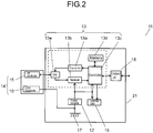
- FIG. 2 is a circuit block diagram of data communication device 11.
- Data communication device 11 includes power source 12, communication unit 13, and communication antenna 14.
- Communication antenna 14 includes communication electrode (Hot electrode) 15 and planar ground electrode (Cold electrode) 16.
- Communication unit 13 is driven by power source 12.
- Communication electrode 15 is connected to communication unit 13.
- Communication unit 13 transmits communication signals to communication electrode 15.
- communication unit 13 receives communication signals from communication electrode 15.
- Ground electrode 16, on the other hand, is connected to ground 17 of communication unit 13.
- Data communication device 11 thus configured is put on the body of wearer 1004.
- Data communication device 11 includes fitting surface 11a and outer surface 11b. Outer surface 11b is positioned opposite fitting surface 11a.
- data communication device 11 is put on with fitting surface 11a facing the body of wearer 1004.
- communication electrode 15 faces the human body.
- data communication device 11 includes this surface provided with communication electrode 15, and fitting surface 11a refers to this surface.
- the communication signals from communication electrode 15 thus fitted to wearer 1004 are transmitted to communication control device 1002 via the body of wearer 1004.
- the communication signals transmitted from communication control device 1002 are received by communication electrode 15 via the body of wearer 1004.
- communication electrode 15 directly touch the body of wearer 1004 when data communication device 11 is put on. In this way, communication signal loss can be reduced. Therefore, communication is stable between data communication device 11 and communication control device 1002. It is to be noted that there may be a small clearance between surface 15a of communication electrode 15 and the human body, so that direct touching of the human body by surface 15a is not limiting. A thin dress or the like may also be interposed between the human body and communication electrode 15. In these cases, however, increased stray capacitance between communication electrode 15 and the body of wearer 1004 causes communication signal attenuation. Therefore, a thickness of the dress or a distance across the clearance may be such that a predetermined level of electric field strength or more can be secured at communication electrode 1002a.
- FIG. 3 is a conceptual diagram of data communication device 11.
- Data communication device 11 includes body case 21 and belt 22.
- Data communication device 11 is held to arm 1004a when belt 22 is fastened. Therefore, belt 22 is worn around arm 1004a and is fastened at its leading end with an immobilizing assembly (described later), thus being fitted and held to arm 1004a.
- FIG. 3 does not illustrate ground 17.
- Body case 21 includes bottom face 21a and side face 21b.
- Belt 22 is joined to body case 21 at side face 21b of body case 21.
- the belt at least partly includes insulator 22a.
- Data communication device 11 is put on with bottom face 21a facing arm 1004a. This means that bottom face 21a of body case 21 is included in the fitting surface.
- Communication electrode 15 is provided to be exposed at bottom face 21a of body case 21.
- one end of ground electrode 16 is connected to ground 17 inside body case 21.
- Ground electrode 16 extends from inside body case 21 to have its opposite end outside body case 21.
- Ground electrode 16 is disposed to face plane 15b that extends, as an extension of surface 15a of communication electrode 15, beyond body case 21 (or from bottom face 21a).
- Ground electrode 16 includes an extending part positioned outside body case 21, and this extending part includes surface 16a facing plane 15b.
- Surface 16a is covered by insulator 22a. Because of this structure, a surface of insulator 22a that is closer to surface 16a of ground electrode 16 is included in the fitting surface. In other words, a belt side facing plane 15b serves as fitting surface 11a.
- insulator 22a can prevent ground electrode 16 from directly touching wearer 1004 when wearer 1004 puts on data communication device 11. Therefore, signals output from a transmission electrode or signals to be received by the transmission electrode do not easily flow toward the ground electrode. Consequently, improved communication sensitivity is achieved between data communication device 11 and communication control device 1002.
- Power source 12 is preferably a secondary battery. This structure can eliminate battery replacements and thus is advantageous in terms of waterproofness. It is to be noted that power source 12 is not limited to the secondary battery and may be a primary battery.
- Communication unit 13 may include those including transmitter 13a, receiver 13b, control circuit 13c, memory 13d, and switch (SW) 13e.
- Communication electrode 15 is connected to an input and an output terminal of switch 13e.
- the input terminal of switch 13e is connected to an output of transmitter 13a.
- the output terminal of switch 13e is connected to an input of receiver 13b.
- Switch 13e switches between reception and transmission. For reception, switch 13e electrically connects communication electrode 15 and receiver 13b.
- switch 13e electrically connects communication electrode 15 and transmitter 13a.
- Memory 13d stores those including identification data (ID data) that identifies, for example, the wearer or the data communication device.
- Control circuit 13c obtains these data from memory 13d and transmits these data to transmitter 13a.
- receiver 13b receives, for example, response signals from communication control device 1002.
- the response signal is indicative of, for example, normal reception of a communication transmitted from data communication device 11 by communication control device 1002.
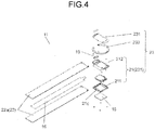
- FIG. 4 is an exploded perspective view of data communication device 11.
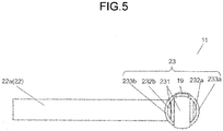
- FIG. 5 is a front view looking at outer surface 11b of data communication device 11.
- FIG. 6 is a right side view of data communication device 11.
- FIG. 7 is a left side view of data communication device 11.
- FIG. 8 is a top view of data communication device 11.
- FIG. 9 is a bottom view of data communication device 11.
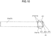
- FIG. 10 is a rear view looking at fitting surface 11a of data communication device 11.
- Data communication device 11 may also include external input and output interface (input and output I/F) 18 and display unit 19. External input and output 18 and display unit 19 are housed in body case 21. Display unit 19 is caused by a control signal from control circuit 13c to light up. Display unit 19 lights up when, for example, a communication signal is transmitted normally from transmitter 13a. Alternatively, display unit 19 lights up when a response signal is received from receiver 13b.
- This configuration enables the wearer to be aware of completion of normal communication between data communication device 11 and communication control device 1002.
- Data communication device 11 can also import external data for transmission to communication control device 1002. If data communication device 11 includes external input and output interface 18, power source 12 can also be supplied with power from an external device via a Universal Serial Bus (USB) cable to be charged.
- USB Universal Serial Bus
- ground electrode 16 is flexible. To be flexible, ground electrode 16 is formed of, for example, a thin metal plate. Alternatively, ground electrode 16 may be made of copper foil that is used for a flexible substrate.
- Ground electrode 16 is preferably covered by insulator 22a also at surface 16b opposite from surface 16a. Because of this structure, ground electrode 16 is contained inside belt 22. Accordingly, unexpected contact between a metal object and belt 22 can be suppressed. Even in such an event, stable communication is achieved between data communication device 11 and communication control device 1002.
- Ground electrode 16 preferably extends to a position close to a leading edge of belt 22. Because of this structure, ground electrode 16 circles the arm when belt 22 is worn around arm 1004a. This structure enables a smaller change of distance between ground electrode 16 and ground electrode 1002b of communication control device 1002 and a smaller change of direction that are not affected by an arm posture including a direction and a position of arm 1004a. Therefore, stable communication is achieved between data communication device 11 and communication control device 1002 without being affected by the arm posture including the direction and position of arm 1004a.
- Body case 21 includes fitting case 211 and outer case 212.
- Communication electrode 15 is disposed in a center of fitting case 211 to be exposed at bottom face 21a.
- Outer case 212 is disposed on an outer side of fitting case 211. Fitting case 211 and outer case 212 are sealed together.
- An electric circuit including communication unit 13 and power source 12 is put in an internal space of body case 21.
- Fitting case 211 preferably includes, outwardly of an edge of communication electrode 15, frame 21c that is made of a resin. This structure can keep communication electrode 15 and ground electrode 16 apart from each other. Thus communication signal attenuation that might be caused by communication signal flow toward the ground electrode can be suppressed.
- Ground electrode 16 is preferably positioned at a distance closer to front face 21d from plane 15b.
- front face 21d is a face of body case 21 that is opposite from bottom face 21a. Therefore, a shoulder, for example, is formed between a side edge of bottom face 21a and a belt base where belt 22 is joined to side face 21b of body case 21. Because of this structure, when belt 22 is worn around arm 1004a, belt 22 comes into contact with the arm at a slight distance from an outer edge of bottom face 21a of body case 21. Therefore, when belt 22 is worn around arm 1004a, ground electrode 16 can be restrained from being at a smaller distance from communication electrode 15 near the belt base.
- communication electrode 15 be substantially flush with bottom face 21a. Because of this structure, a shorter clearance can be achieved between communication electrode 15 and arm 1004a when data communication device 11 is put on the arm. Communication electrode 15 thus easily comes into contact with arm 1004a. Consequently, during transmission of a communication signal to arm 1004a, communication signal loss can be reduced. It is to be noted that communication electrode 15 may project from bottom face 21a, so that the structure in which communication electrode 15 is substantially flush with bottom face 21a is not limiting. It is also to be noted that communication electrode 15 may be disposed, for example, on the belt side (serving as fitting surface 11a) that faces plane 15b, so that exposing communication electrode 15 at fitting surface 11a of body case 21 is not limiting.
- FIG. 11 is a perspective view of data communication device 11.
- FIG. 12 is a perspective view illustrating data communication device 11 with belt 22 fastened.
- the data communication device also includes buckle 23.
- Buckle 23 is put on with fitting surface 11a circling the arm while facing arm 1004a.
- Belt 22 has its length adjusted by buckle 23, so that belt 22 can be held around the arm.
- Data communication device 11 is preferably put on with communication electrode 15 directly touching the human body at its surface 15a. However, every person has a different arm thickness. Therefore, it is desirable that the length of belt 22 be adjusted freely.
- buckle 23 desirably has a buckle mechanism. As is described below, the buckle mechanism is an internally provided mechanism that immobilizes the belt which is pressed by a pressing device ( FIG. 10 ). This means that buckle 23 does not have a pin that immobilizes belt 22.
- belt 22 is not formed with pin holes that each allow passage of the pin to immobilize belt 22. Because the length of belt 22 can be adjusted freely by this mechanism, a reduced clearance can be achieved between communication electrode 15 and arm 1004a no matter how thick arm 1004a can be. Therefore, communication signal loss can be reduced.
- ground electrode 16 needs to be formed to avoid the pin holes.
- ground electrode 16 has voids that correspond to the pin holes, respectively.
- belt 22 with the buckle mechanism does not have to have the pin holes, so that ground electrode 16 does not have to have those voids corresponding to the pin holes. Therefore, any dimension of ground electrode 16 can be uniform without being affected by the direction of arm 1004a.
- ground electrode 16 has, in a direction orthogonal to a direction from its base to its leading edge, a width that is uniform from its base to its leading edge.
- buckle 23 having the buckle mechanism includes, for example, buckle body 231, space 232, and an immobilizing assembly 233.
- Immobilizing assembly 233 is joined to buckle body 231.
- Space 232 is formed between buckle body 231 and immobilizing assembly 233.
- Buckle 23 is disposed at an outer-surface-end side of body case 21.
- body case 21 may also serve as a part of buckle 23.
- buckle 23 may include outer case 212 forming buckle body 231, and fitting case 211 having bottom face 21a as fitting surface 11a.
- bottom face 21a of fitting case 211 defines fitting surface 11a of buckle 23.
- front face 21d of outer case 212 also serves as a front face of buckle body 231. Having this structure, buckle 23 can have a reduced thickness.
- buckle 23 and body case 21 can be put into one place on belt 22. Therefore, a satisfactory fit is provided when data communication device 11 is put on arm 1004a.
- front face 21d of body case 21 may be independent of buckle body 231, so that the structure in which body case 21 also serves as buckle body 231 is not limiting.
- buckle 23 may include buckle body 231, outer case 212, and fitting case 211.
- buckle body 231 is fixed to body case 21 while overlapping the outer-surface-end side of body case 21, namely, front face 21d. Because of this structure, buckle 23 can be replaced with ease. Therefore, wearer 1004 can replace buckle 23 with buckle 23 having a design that is to his or her taste. Even in this case, buckle 23 and body case 21 can be put into one place on belt 22.
- Body case 21 may be disposed at a different position than buckle 23, so that disposing body case 21 at a fitting-surface-end side of buckle 23 is not limiting.
- body case 21 is not disposed to overlap buckle 23.
- body case 21 is joined to belt 22 between buckle 23 and the leading edge of belt 22.
- Belt 22 is joined to buckle 23.
- Belt 22 is joined to buckle body 231 in this case.
- communication electrode 15 may be disposed at a fitting-surface-end side of belt 22 or buckle body 231, so that disposing communication electrode 15 at body case 21 is not limiting.
- Immobilizing assembly 233 preferably includes immobilizing part 233a and immobilizing part 233b. Immobilizing parts 233a and 233b are provided side by side in a direction that belt 22 passes. Belt 22 is inserted into space 232a between immobilizing part 233a and buckle body 231 in a direction from fitting surface 11a toward outer surface 11b. Buckle 23 is then inserted into space 232b between immobilizing part 233b and buckle body 231 in a direction from outer surface 11b toward fitting surface 11a. Because of this structure, insertion of belt 22 takes place at two locations: one between immobilizing part 233a and buckle body 231 and the other between immobilizing part 233b and buckle body 231. Therefore, belt 22 is not easily slackened.
- ground electrode 16 is provided at an end of belt 22 that is opposite from where belt 22 is joined to body case 21.
- ground electrode 16 desirably extends to have its leading edge at the leading edge of belt 22. Having this structure, ground electrode 16 circles arm 1004a. Consequently, stable communication can be achieved without being affected by the direction of arm 1004a.
- ground electrode 16 may extend to where its leading edge at least overlaps buckle 23 with belt 22 being inserted through space 232, so that ground electrode 16 that extends to have its leading edge at the leading edge of belt 22 is not limiting.
- outer case 212 or buckle body 231 is preferably made of a metal to be electrically connected to ground electrode 16.
- outer case 212 or buckle body 231 also functions as a ground electrode.
- Resulting ground electrode 16 thus formed in this structure can circle arm 1004a.
- belt 22 passes by respective outer surfaces of outer case 212 and buckle body 231.
- Insulator 22a is a covering serving as a surface layer of belt 22. This can mean that there is a smaller possibility of contact between wearer 1004 and outer case 212 or buckle body 231. This can also mean that there is a smaller possibility of contact between a metal object and outer case 212 or buckle body 231. Consequently, stable communication can be achieved.
- ground electrode 16 extends so that its leading edge overlaps its base.
- Ground electrode 16 thus formed to have this structure can circle arm 1004a.
- each of outer case 212 and buckle body 231 can be made of a resin. If outer case 212 and buckle body 231 are each made of the resin, stable communication can be achieved even when a metal object or the like comes into contact with, for example, outer case 212 or buckle body 231.
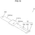
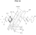
- FIG. 25 is a perspective view of data communication device 51 which is a variation.
- FIG. 26 is an exploded perspective view of data communication device 51.
- Data communication device 51 is the variation of data communication device 11.
- data communication device 51 includes belt 52 instead of belt 22.
- Belt 52 differs from belt 22 in that belt 52 connects with two opposite side faces of body case 21.
- Ground electrode 16 is contained inside belt 52 that extends from both of the side faces of body case 21. In other words, ground electrode 16 extends out of body case 21 in opposite directions. Therefore, body case 21 is disposed at a middle part of belt 52.
- Buckle 53 is a pin type buckle.
- buckle 53 includes ring 531, opening 532, and pin holes 533.
- Ring 531 is formed at one end of belt 52.
- Ring 531 has opening 532 that allows passage of the belt.
- Pin holes 533 are formed between ring 531 and body case 21.
- An opposite end of belt 52 on the other hand, has pin 534.
- belt 52 has the plurality of pin holes 533. Therefore, pin 534 is inserted into any one of the plurality of pin holes 533 to adjust length of belt 52.
- wearer 1004 inserts pin 534 into pin hole 533 that is right for his or her arm thickness to fit data communication device 51 to arm 1004a.
- Ground electrode 54 is contained inside belt 52.
- Ground electrode 54 here has slit 541 corresponding to an area formed with the plurality of pin holes 533.
- a data communication device is effective in achieving stable communication and thus is useful as a device that is fitted to a human body for intra-body communication.
Landscapes
- Engineering & Computer Science (AREA)
- Computer Networks & Wireless Communication (AREA)
- Signal Processing (AREA)
- Life Sciences & Earth Sciences (AREA)
- Health & Medical Sciences (AREA)
- Biomedical Technology (AREA)
- Surgery (AREA)
- Pathology (AREA)
- Physics & Mathematics (AREA)
- Heart & Thoracic Surgery (AREA)
- Medical Informatics (AREA)
- Molecular Biology (AREA)
- Biophysics (AREA)
- Animal Behavior & Ethology (AREA)
- General Health & Medical Sciences (AREA)
- Public Health (AREA)
- Veterinary Medicine (AREA)
- Measurement And Recording Of Electrical Phenomena And Electrical Characteristics Of The Living Body (AREA)
- Near-Field Transmission Systems (AREA)
Applications Claiming Priority (3)
| Application Number | Priority Date | Filing Date | Title |
|---|---|---|---|
| JP2017244665A JP2019114833A (ja) | 2017-12-21 | 2017-12-21 | データ通信装置 |
| JP2017244666A JP7119368B2 (ja) | 2017-12-21 | 2017-12-21 | データ通信装置 |
| PCT/JP2018/042934 WO2019123955A1 (ja) | 2017-12-21 | 2018-11-21 | データ通信装置 |
Publications (2)
| Publication Number | Publication Date |
|---|---|
| EP3731438A1 true EP3731438A1 (de) | 2020-10-28 |
| EP3731438A4 EP3731438A4 (de) | 2021-05-26 |
Family
ID=66992781
Family Applications (1)
| Application Number | Title | Priority Date | Filing Date |
|---|---|---|---|
| EP18891979.9A Withdrawn EP3731438A4 (de) | 2017-12-21 | 2018-11-21 | Datenkommunikationsvorrichtung |
Country Status (4)
| Country | Link |
|---|---|
| US (1) | US20200252140A1 (de) |
| EP (1) | EP3731438A4 (de) |
| CN (1) | CN111373669A (de) |
| WO (1) | WO2019123955A1 (de) |
Family Cites Families (5)
| Publication number | Priority date | Publication date | Assignee | Title |
|---|---|---|---|---|
| AU5671396A (en) * | 1995-05-08 | 1996-11-29 | Massachusetts Institute Of Technology | System for non-contact sensing and signalling using human bo dy as signal transmission medium |
| JP2003134009A (ja) | 2001-10-25 | 2003-05-09 | Matsushita Electric Works Ltd | データ通信装置 |
| JP2006239716A (ja) | 2005-03-01 | 2006-09-14 | Kobe Steel Ltd | 連続鋳造方法 |
| JP4562783B2 (ja) * | 2008-03-27 | 2010-10-13 | 日本電信電話株式会社 | 電界通信用ベルト |
| JP3208310U (ja) * | 2016-10-14 | 2017-01-05 | 忠 塩生 | バックル |
-
2018
- 2018-11-21 US US16/652,156 patent/US20200252140A1/en not_active Abandoned
- 2018-11-21 WO PCT/JP2018/042934 patent/WO2019123955A1/ja not_active Ceased
- 2018-11-21 EP EP18891979.9A patent/EP3731438A4/de not_active Withdrawn
- 2018-11-21 CN CN201880074837.7A patent/CN111373669A/zh active Pending
Also Published As
| Publication number | Publication date |
|---|---|
| US20200252140A1 (en) | 2020-08-06 |
| EP3731438A4 (de) | 2021-05-26 |
| WO2019123955A1 (ja) | 2019-06-27 |
| CN111373669A (zh) | 2020-07-03 |
Similar Documents
| Publication | Publication Date | Title |
|---|---|---|
| EP3807724B1 (de) | Am handgelenk tragbare elektronische vorrichtung mit gehäusebasierter schleifenantenne | |
| US11329365B2 (en) | Coupled multi-bands antennas in wearable wireless devices | |
| EP3170226B1 (de) | Antenne für elektronische vorrichtung | |
| EP4398048B1 (de) | Tragbare elektronische vorrichtung und montageverfahren | |
| KR101835337B1 (ko) | 휴대용 음향기기 | |
| KR20200042611A (ko) | 단일 절연성 부분을 이용한 안테나 및 그것을 포함하는 전자 장치 | |
| KR20200022803A (ko) | 안테나를 포함하는 전자 장치 | |
| KR102846543B1 (ko) | 안테나를 포함하는 전자 장치 | |
| US11445284B2 (en) | Portable audio equipment | |
| KR102819148B1 (ko) | 웨어러블 전자 장치 및 그에 적용되는 광학 필름 | |
| EP3731438A1 (de) | Datenkommunikationsvorrichtung | |
| JP7501008B2 (ja) | アンテナ装置、ウェアラブルデバイス、位置監視システム、及びアンテナ装置の製造方法 | |
| JP7119368B2 (ja) | データ通信装置 | |
| WO2015029610A1 (ja) | バンド型無線機 | |
| US9647710B2 (en) | Electronic device including communications module | |
| EP4322711B1 (de) | Elektronische vorrichtung mit leiterplatte | |
| JP2019114833A (ja) | データ通信装置 | |
| KR20210054336A (ko) | 그립 감지 방법 및 이를 지원하는 전자 장치 | |
| JP2016131808A (ja) | 生体情報収集装置と生体情報収集装置用装着部材 | |
| CN109157759B (zh) | 腕带式激光治疗仪 | |
| US20160013825A1 (en) | Wireless device attaching band, and wireless device | |
| US20260104736A1 (en) | Wearable electronic device | |
| JP4449369B2 (ja) | スイッチ | |
| KR20240011590A (ko) | 모터 하우징을 포함하는 전자 장치 | |
| KR20170089482A (ko) | 손목시계 형태의 전자 장치 |
Legal Events
| Date | Code | Title | Description |
|---|---|---|---|
| STAA | Information on the status of an ep patent application or granted ep patent |
Free format text: STATUS: THE INTERNATIONAL PUBLICATION HAS BEEN MADE |
|
| PUAI | Public reference made under article 153(3) epc to a published international application that has entered the european phase |
Free format text: ORIGINAL CODE: 0009012 |
|
| STAA | Information on the status of an ep patent application or granted ep patent |
Free format text: STATUS: REQUEST FOR EXAMINATION WAS MADE |
|
| 17P | Request for examination filed |
Effective date: 20200331 |
|
| AK | Designated contracting states |
Kind code of ref document: A1 Designated state(s): AL AT BE BG CH CY CZ DE DK EE ES FI FR GB GR HR HU IE IS IT LI LT LU LV MC MK MT NL NO PL PT RO RS SE SI SK SM TR |
|
| AX | Request for extension of the european patent |
Extension state: BA ME |
|
| RIC1 | Information provided on ipc code assigned before grant |
Ipc: H04B 13/00 20060101AFI20210118BHEP |
|
| DAV | Request for validation of the european patent (deleted) | ||
| DAX | Request for extension of the european patent (deleted) | ||
| A4 | Supplementary search report drawn up and despatched |
Effective date: 20210422 |
|
| RIC1 | Information provided on ipc code assigned before grant |
Ipc: H04B 13/00 20060101AFI20210416BHEP |
|
| STAA | Information on the status of an ep patent application or granted ep patent |
Free format text: STATUS: THE APPLICATION IS DEEMED TO BE WITHDRAWN |
|
| 18D | Application deemed to be withdrawn |
Effective date: 20211123 |