EP3732023B1 - Generative fertigung unter verwendung von polyimid enthaltenden formulierungen - Google Patents
Generative fertigung unter verwendung von polyimid enthaltenden formulierungen Download PDFInfo
- Publication number
- EP3732023B1 EP3732023B1 EP18836915.1A EP18836915A EP3732023B1 EP 3732023 B1 EP3732023 B1 EP 3732023B1 EP 18836915 A EP18836915 A EP 18836915A EP 3732023 B1 EP3732023 B1 EP 3732023B1
- Authority
- EP
- European Patent Office
- Prior art keywords
- printing
- dispensing
- nozzles
- formulation
- polyimide precursor
- Prior art date
- Legal status (The legal status is an assumption and is not a legal conclusion. Google has not performed a legal analysis and makes no representation as to the accuracy of the status listed.)
- Active
Links
Images








Classifications
-
- B—PERFORMING OPERATIONS; TRANSPORTING
- B29—WORKING OF PLASTICS; WORKING OF SUBSTANCES IN A PLASTIC STATE IN GENERAL
- B29C—SHAPING OR JOINING OF PLASTICS; SHAPING OF MATERIAL IN A PLASTIC STATE, NOT OTHERWISE PROVIDED FOR; AFTER-TREATMENT OF THE SHAPED PRODUCTS, e.g. REPAIRING
- B29C64/00—Additive manufacturing, i.e. manufacturing of three-dimensional [3D] objects by additive deposition, additive agglomeration or additive layering, e.g. by 3D printing, stereolithography or selective laser sintering
- B29C64/10—Processes of additive manufacturing
- B29C64/106—Processes of additive manufacturing using only liquids or viscous materials, e.g. depositing a continuous bead of viscous material
- B29C64/124—Processes of additive manufacturing using only liquids or viscous materials, e.g. depositing a continuous bead of viscous material using layers of liquid which are selectively solidified
-
- B—PERFORMING OPERATIONS; TRANSPORTING
- B29—WORKING OF PLASTICS; WORKING OF SUBSTANCES IN A PLASTIC STATE IN GENERAL
- B29C—SHAPING OR JOINING OF PLASTICS; SHAPING OF MATERIAL IN A PLASTIC STATE, NOT OTHERWISE PROVIDED FOR; AFTER-TREATMENT OF THE SHAPED PRODUCTS, e.g. REPAIRING
- B29C64/00—Additive manufacturing, i.e. manufacturing of three-dimensional [3D] objects by additive deposition, additive agglomeration or additive layering, e.g. by 3D printing, stereolithography or selective laser sintering
- B29C64/10—Processes of additive manufacturing
- B29C64/106—Processes of additive manufacturing using only liquids or viscous materials, e.g. depositing a continuous bead of viscous material
- B29C64/124—Processes of additive manufacturing using only liquids or viscous materials, e.g. depositing a continuous bead of viscous material using layers of liquid which are selectively solidified
- B29C64/129—Processes of additive manufacturing using only liquids or viscous materials, e.g. depositing a continuous bead of viscous material using layers of liquid which are selectively solidified characterised by the energy source therefor, e.g. by global irradiation combined with a mask
-
- B—PERFORMING OPERATIONS; TRANSPORTING
- B29—WORKING OF PLASTICS; WORKING OF SUBSTANCES IN A PLASTIC STATE IN GENERAL
- B29C—SHAPING OR JOINING OF PLASTICS; SHAPING OF MATERIAL IN A PLASTIC STATE, NOT OTHERWISE PROVIDED FOR; AFTER-TREATMENT OF THE SHAPED PRODUCTS, e.g. REPAIRING
- B29C64/00—Additive manufacturing, i.e. manufacturing of three-dimensional [3D] objects by additive deposition, additive agglomeration or additive layering, e.g. by 3D printing, stereolithography or selective laser sintering
- B29C64/20—Apparatus for additive manufacturing; Details thereof or accessories therefor
- B29C64/205—Means for applying layers
- B29C64/209—Heads; Nozzles
-
- B—PERFORMING OPERATIONS; TRANSPORTING
- B29—WORKING OF PLASTICS; WORKING OF SUBSTANCES IN A PLASTIC STATE IN GENERAL
- B29C—SHAPING OR JOINING OF PLASTICS; SHAPING OF MATERIAL IN A PLASTIC STATE, NOT OTHERWISE PROVIDED FOR; AFTER-TREATMENT OF THE SHAPED PRODUCTS, e.g. REPAIRING
- B29C64/00—Additive manufacturing, i.e. manufacturing of three-dimensional [3D] objects by additive deposition, additive agglomeration or additive layering, e.g. by 3D printing, stereolithography or selective laser sintering
- B29C64/20—Apparatus for additive manufacturing; Details thereof or accessories therefor
- B29C64/264—Arrangements for irradiation
- B29C64/277—Arrangements for irradiation using multiple radiation means, e.g. micromirrors or multiple light-emitting diodes [LED]
-
- B—PERFORMING OPERATIONS; TRANSPORTING
- B29—WORKING OF PLASTICS; WORKING OF SUBSTANCES IN A PLASTIC STATE IN GENERAL
- B29C—SHAPING OR JOINING OF PLASTICS; SHAPING OF MATERIAL IN A PLASTIC STATE, NOT OTHERWISE PROVIDED FOR; AFTER-TREATMENT OF THE SHAPED PRODUCTS, e.g. REPAIRING
- B29C64/00—Additive manufacturing, i.e. manufacturing of three-dimensional [3D] objects by additive deposition, additive agglomeration or additive layering, e.g. by 3D printing, stereolithography or selective laser sintering
- B29C64/30—Auxiliary operations or equipment
- B29C64/386—Data acquisition or data processing for additive manufacturing
- B29C64/393—Data acquisition or data processing for additive manufacturing for controlling or regulating additive manufacturing processes
-
- B—PERFORMING OPERATIONS; TRANSPORTING
- B33—ADDITIVE MANUFACTURING TECHNOLOGY
- B33Y—ADDITIVE MANUFACTURING, i.e. MANUFACTURING OF THREE-DIMENSIONAL [3D] OBJECTS BY ADDITIVE DEPOSITION, ADDITIVE AGGLOMERATION OR ADDITIVE LAYERING, e.g. BY 3D PRINTING, STEREOLITHOGRAPHY OR SELECTIVE LASER SINTERING
- B33Y10/00—Processes of additive manufacturing
-
- B—PERFORMING OPERATIONS; TRANSPORTING
- B33—ADDITIVE MANUFACTURING TECHNOLOGY
- B33Y—ADDITIVE MANUFACTURING, i.e. MANUFACTURING OF THREE-DIMENSIONAL [3D] OBJECTS BY ADDITIVE DEPOSITION, ADDITIVE AGGLOMERATION OR ADDITIVE LAYERING, e.g. BY 3D PRINTING, STEREOLITHOGRAPHY OR SELECTIVE LASER SINTERING
- B33Y30/00—Apparatus for additive manufacturing; Details thereof or accessories therefor
-
- B—PERFORMING OPERATIONS; TRANSPORTING
- B33—ADDITIVE MANUFACTURING TECHNOLOGY
- B33Y—ADDITIVE MANUFACTURING, i.e. MANUFACTURING OF THREE-DIMENSIONAL [3D] OBJECTS BY ADDITIVE DEPOSITION, ADDITIVE AGGLOMERATION OR ADDITIVE LAYERING, e.g. BY 3D PRINTING, STEREOLITHOGRAPHY OR SELECTIVE LASER SINTERING
- B33Y50/00—Data acquisition or data processing for additive manufacturing
- B33Y50/02—Data acquisition or data processing for additive manufacturing for controlling or regulating additive manufacturing processes
-
- C—CHEMISTRY; METALLURGY
- C08—ORGANIC MACROMOLECULAR COMPOUNDS; THEIR PREPARATION OR CHEMICAL WORKING-UP; COMPOSITIONS BASED THEREON
- C08G—MACROMOLECULAR COMPOUNDS OBTAINED OTHERWISE THAN BY REACTIONS ONLY INVOLVING UNSATURATED CARBON-TO-CARBON BONDS
- C08G73/00—Macromolecular compounds obtained by reactions forming a linkage containing nitrogen with or without oxygen or carbon in the main chain of the macromolecule, not provided for in groups C08G12/00 - C08G71/00
- C08G73/06—Polycondensates having nitrogen-containing heterocyclic rings in the main chain of the macromolecule
- C08G73/10—Polyimides; Polyester-imides; Polyamide-imides; Polyamide acids or similar polyimide precursors
- C08G73/12—Unsaturated polyimide precursors
-
- C—CHEMISTRY; METALLURGY
- C08—ORGANIC MACROMOLECULAR COMPOUNDS; THEIR PREPARATION OR CHEMICAL WORKING-UP; COMPOSITIONS BASED THEREON
- C08G—MACROMOLECULAR COMPOUNDS OBTAINED OTHERWISE THAN BY REACTIONS ONLY INVOLVING UNSATURATED CARBON-TO-CARBON BONDS
- C08G73/00—Macromolecular compounds obtained by reactions forming a linkage containing nitrogen with or without oxygen or carbon in the main chain of the macromolecule, not provided for in groups C08G12/00 - C08G71/00
- C08G73/06—Polycondensates having nitrogen-containing heterocyclic rings in the main chain of the macromolecule
- C08G73/10—Polyimides; Polyester-imides; Polyamide-imides; Polyamide acids or similar polyimide precursors
- C08G73/12—Unsaturated polyimide precursors
- C08G73/128—Unsaturated polyimide precursors the unsaturated precursors containing heterocyclic moieties in the main chain
-
- B—PERFORMING OPERATIONS; TRANSPORTING
- B29—WORKING OF PLASTICS; WORKING OF SUBSTANCES IN A PLASTIC STATE IN GENERAL
- B29K—INDEXING SCHEME ASSOCIATED WITH SUBCLASSES B29B, B29C OR B29D, RELATING TO MOULDING MATERIALS OR TO MATERIALS FOR MOULDS, REINFORCEMENTS, FILLERS OR PREFORMED PARTS, e.g. INSERTS
- B29K2079/00—Use of polymers having nitrogen, with or without oxygen or carbon only, in the main chain, not provided for in groups B29K2061/00 - B29K2077/00, as moulding material
- B29K2079/08—PI, i.e. polyimides or derivatives thereof
Definitions
- the present invention in some embodiments thereof, relates to additive manufacturing and, more particularly, but not exclusively, to additive manufacturing using polyimide-containing formulations.
- Additive manufacturing is generally a process in which a three-dimensional (3D) object is manufactured utilizing a computer model of the objects. Such a process is used in various fields, such as design related fields for purposes of visualization, demonstration and mechanical prototyping, as well as for rapid manufacturing (RM).
- 3D three-dimensional
- the basic operation of any AM system consists of slicing a three-dimensional computer model into thin cross sections, translating the result into two-dimensional position data and feeding the data to control equipment which manufacture a three-dimensional structure in a layerwise manner.
- AM technologies exist, amongst which are stereolithography, digital light processing (DLP), and three dimensional (3D) printing, 3D inkjet printing in particular.
- DLP digital light processing
- 3D printing 3D inkjet printing
- Such techniques are generally performed by layer by layer deposition and solidification of one or more building materials, typically photopolymerizable (photocurable) materials.
- a building material is dispensed from a printing head having a set of nozzles to deposit layers on a supporting structure.
- the layers may then solidify, harden or be cure, optionally using a suitable device.
- a printing system utilized in additive manufacturing may include a receiving medium and one or more printing heads.
- the receiving medium can be, for example, a fabrication tray that may include a horizontal surface to carry the material dispensed from the printing head.
- the printing head may be, for example, an ink jet head having a plurality of dispensing nozzles arranged in an array of one or more rows along the longitudinal axis of the printing head.
- the printing head may be located such that its longitudinal axis is substantially parallel to the indexing direction.
- the printing system may further include a controller, such as a microprocessor to control the printing process, including the movement of the printing head according to a pre-defined scanning plan (e.g., a CAD configuration converted to a Stereo Lithography (STL) format and programmed into the controller).
- the printing head may include a plurality of jetting nozzles. The jetting nozzles dispense material onto the receiving medium to create the layers representing cross sections of a 3D object.
- the curing energy is typically radiation, for example, UV radiation.
- the printing system may include a leveling device for leveling and/or establishing the height of each layer after deposition and at least partial solidification, prior to the deposition of a subsequent layer.
- the building materials may include modeling materials and support materials, which form the object and the temporary support constructions supporting the object as it is being built, respectively.
- the modeling material (which may include one or more material(s)) is deposited to produce the desired object/s and the support material (which may include one or more material(s)) is used, with or without modeling material elements, to provide support structures for specific areas of the object during building and assure adequate vertical placement of subsequent object layers, e.g., in cases where objects include overhanging features or shapes such as curved geometries, negative angles, voids, and so on.
- Both the modeling and support materials are preferably liquid at the working temperature at which they are dispensed, and subsequently harden or solidify, typically upon exposure to curing energy (e.g., UV curing), to form the required layer shape.
- curing energy e.g., UV curing
- support structures are removed to reveal the final shape of the fabricated 3D object.
- U.S. Patent Application having Publication No. 2010/0191360 discloses a system which comprises a solid freeform fabrication apparatus having a plurality of printing heads, a building material supply apparatus configured to supply a plurality of building materials to the fabrication apparatus, and a control unit configured for controlling the fabrication and supply apparatus.
- the system has several operation modes. In one mode, all printing heads operate during a single building scan cycle of the fabrication apparatus. In another mode, one or more of the printing heads is not operative during a single building scan cycle or part thereof.
- the building material is selectively jetted from one or more printing heads and deposited onto a fabrication tray in consecutive layers according to a pre-determined configuration as defined by a software file.
- U.S. Patent No. 9,227,365 discloses methods and systems for solid freeform fabrication of shelled objects, constructed from a plurality of layers and a layered core constituting core regions and a layered shell constituting envelope regions.
- the Polyjet TM technology allows control over the position and composition of each voxel (volume pixel), which affords enormous design versatility and digital programming of multi-material structures.
- Other advantages of the Polyjet TM technology is the very high printing resolution, up to 14 ⁇ m layer height, and the ability to print multiple materials simultaneously, in a single object.
- This multi-material 3D printing process often serves for fabrication of complex parts and structures that are comprised of elements having different stiffness, performance, color or transparency. New ranges of materials, programmed at the voxel level, can be created by the Polyjet TM printing process, using only few starting materials.
- the uncured building material should feature the following characteristics: a relatively low viscosity (e.g., Brookfield Viscosity of up to 50 cps, or up to 35 cps, preferably from 8 to 25 cps) at the working (e.g., jetting) temperature; Surface tension of from about 25 to about 55 dyn/cm, preferably from about 25 to about 40 dyn/cm; and a Newtonian liquid behavior and high reactivity to a selected curing condition, to enable fast solidification of the jetted layer upon exposure to a curing condition, of no more than 1 minute, preferably no more than 20 seconds.
- a relatively low viscosity e.g., Brookfield Viscosity of up to 50 cps, or up to 35 cps, preferably from 8 to 25 cps
- Surface tension of from about 25 to about 55 dyn/cm, preferably from about 25 to about 40 dyn/cm
- Additional requirements include low boiling point solvents (if solvents are used), e.g., featuring bp lower than 200 or lower than 190 °C, yet characterized preferably by low evaporation rate at the working (e.g., jetting) temperature, and, if the building material includes solid particles, these should feature an average size of no more than 2 microns.
- curable e.g., polymerizable
- materials that provide polymeric materials featuring a variety of properties, ranging, for example, from stiff and hard materials (e.g., curable formulations marketed as the Vero TM Family materials) to soft and flexible materials (e.g., curable formulations marketed as the Tango TM and Agilus TM families), and including also objects made using Digital ABS, which contain a multi-material made of two starting materials (e.g., RGD515 & RGD535/531), and simulate properties of engineering plastic.
- Most of the currently practiced PolyJet materials are curable materials which harden or solidify upon exposure to radiation, mostly UV radiation and/or heat.
- Polyimides are very promising materials for additive manufacturing such as 3D inkjet printing, as these materials feature desirable characteristics such as high thermal stability, excellent mechanical properties, wear resistance, radiation resistance, inertness to solvents, low dielectric constant, and good adhesion strengths.
- Some polyimides are thermoplastic and some are thermosetting polymer. The properties of the polyimide can be determined by the chemical structure of the monomeric precursor and/or the polymerization mechanism, with an endless number of polymeric precursors and an enormous range of applications of the resulting polyimides.
- PCT/IB2017/054054 filed July 5, 2017, describes solutions containing a bismaleimide (BMI) as a chemical precursor of a polyimide, in a suitable solvent, optionally along with a polymerization initiator (e.g., photoinitiator), a surfactant, a stabilizer, a reinforcer, or any other additive.
- BMI bismaleimide
- EP Patent No. 1857478B1 describes a curable formulation for inkjet printing, which comprises a bis-allyl-nadi-imide compound as defined by Formula I therein, a bismaleimide as defined by Formula II therein, and a diluent which comprises a polymerizable material and optionally an organic solvent.
- Additional background art includes WO 2016/193934 A1 by the present assignee, which describes using polyimide precursor within a sintering inducing formulation, in additive manufacturing that utilizes a catalytic ink.
- the present invention there is provided a method of additive manufacturing of a three-dimensional object, as disclosed in claim 1, the method comprises: dispensing from a first array of nozzles a modeling material formulation containing a polyimide precursor to form a layer in a configured pattern corresponding to a shape of a slice of the object; applying to the layer ultraviolet radiation and infrared radiation from two different radiation sources; and repeating the dispensing and the application of radiation to form a plurality of layers in configured patterns corresponding to shapes of other slices of the object.
- a computer software product as disclosed in claim 3, which comprises a computer-readable medium in which program instructions are stored, which instructions, when read by a computerized controller of an additive manufacturing system, cause the system to execute the method as delineated above and optionally and preferably as further detailed below.
- a system for fabricating a three-dimensional object by additive manufacturing comprises: two or more arrays of nozzles, having at least a first array of nozzles configured for dispensing a modeling material containing a polyimide precursor, and a second array of nozzles configured for dispensing a support material; and a controller having a circuit configured to execute the method as delineated above and optionally and preferably as further detailed below.
- the first array of nozzles and the second array of nozzles are both located in the same printing head.
- the first and the second arrays of nozzles are located in separate printing heads, wherein the first array of nozzles is located in a first printing head, and the second array of nozzles is located in a second printing head.
- the infrared radiation is applied by performing a single scan of the infrared radiation over the layer.
- the infrared radiation is applied by performing a plurality of scans of the infrared radiation over the layer.
- the infrared radiation is applied by performing at least four scans, more preferably from about four scans to about eight scans, of the infrared radiation over the layer.
- the infrared radiation is applied at a power of at least 750 watts, more preferably at least 850 watts, e.g., about 1000 watts.
- the infrared radiation is applied by two infrared light sources.
- the dispensing from the first array of nozzles is by applying voltage pulses to the first array of nozzles, the voltage pulses being characterized by a pulse width of from about 6.0 ⁇ s to about 6.4 ⁇ s, more preferably from about 6.1 ⁇ s to about 6.3 ⁇ s.
- a viscosity of the material formulation containing the polyimide precursor is from about 12 cP to about 18 cP.
- the dispensing is executed to dispense the material formulation containing the polyimide precursor in droplets having a weight of from about 50 ng to about 90 ng.
- the dispensing comprises applying voltage at a frequency of from about 15 kHz to about 25 kHz to the first array of nozzles dispensing the material formulation containing the polyimide precursor.
- the polyimide precursor is bismaleimide.
- the polyimide precursor has a molecular weight of from 200 to 2000 Daltons.
- the polyimide precursor the polyimide precursor is represented by Formula I: wherein: L is a linking moiety; and R 1 -R 4 are each independently selected from hydrogen, alkyl and cycloalkyl.
- R 1 -R 4 are each hydrogen.
- the linking moiety L is or comprises a hydrocarbon.
- the hydrocarbon comprises two or more alkylene chains that are connected therebetween via a branching unit.
- the branching unit comprises or consists of a cycloalkyl.
- the formulation containing the polyimide precursor further comprises an organic solvent.
- the organic solvent is a polar organic solvent.
- the organic solvent has a boiling temperature lower than 190 °C and/or an evaporation rate lower than 1, or lower than 0.5.
- a weight ratio of the polyimide and the organic solvent in the formulation ranges from 50:50 to 90:10.
- Implementation of the method and/or system of embodiments of the invention can involve performing or completing selected tasks manually, automatically, or a combination thereof. Moreover, according to actual instrumentation and equipment of embodiments of the method and/or system of the invention, several selected tasks could be implemented by hardware, by software or by firmware or by a combination thereof using an operating system.
- a data processor such as a computing platform for executing a plurality of instructions.
- the data processor includes a volatile memory for storing instructions and/or data and/or a non-volatile storage, for example, a magnetic hard-disk and/or removable media, for storing instructions and/or data.
- a network connection is provided as well.
- a display and/or a user input device such as a keyboard or mouse are optionally provided as well.
- the present invention in some embodiments thereof, relates to additive manufacturing and, more particularly, but not exclusively, to additive manufacturing using polyimide-containing formulations.
- the method and system of the present embodiments manufacture three-dimensional objects based on computer object data in a layerwise manner by forming a plurality of layers in a configured pattern corresponding to the shape of the objects.
- the computer object data can be in any known format, including, without limitation, a Standard Tessellation Language (STL) or a StereoLithography Contour (SLC) format, Virtual Reality Modeling Language (VRML), Additive Manufacturing File (AMF) format, Drawing Exchange Format (DXF), Polygon File Format (PLY) or any other format suitable for Computer-Aided Design (CAD).
- STL Standard Tessellation Language
- SLC StereoLithography Contour
- VRML Virtual Reality Modeling Language
- AMF Additive Manufacturing File
- DXF Drawing Exchange Format
- PLY Polygon File Format
- CAD Computer-Aided Design
- object describes a final product of the additive manufacturing. This term refers to the product obtained by a method as described herein, after removal of the support material, if such has been used as part of the building material.
- the "object” therefore essentially consists (at least 95 weight percents) of a hardened (e.g., cured) modeling material.
- object refers to a whole object or a part thereof.
- Each layer is formed by additive manufacturing apparatus which scans a two-dimensional surface and patterns it. While scanning, the apparatus visits a plurality of target locations on the two-dimensional layer or surface, and decides, for each target location or a group of target locations, whether or not the target location or group of target locations is to be occupied by building material formulation, and which type of building material formulation is to be delivered thereto. The decision is made according to a computer image of the surface.
- the AM comprises three-dimensional printing, more preferably three-dimensional inkjet printing.
- a building material formulation is dispensed from a printing head having one or more arrays of nozzles to deposit building material formulation in layers on a supporting structure.
- the AM apparatus thus dispenses building material formulation in target locations which are to be occupied and leaves other target locations void.
- the apparatus typically includes a plurality of arrays of nozzles, each of which can be configured to dispense a different building material formulation.
- different target locations can be occupied by different building material formulations.
- the types of building material formulations can be categorized into two major categories: modeling material formulation and support material formulation.
- the support material formulation serves as a supporting matrix or construction for supporting the object or object parts during the fabrication process and/or other purposes, e.g., providing hollow or porous objects. Support constructions may additionally include modeling material formulation elements, e.g. for further support strength.
- the modeling material formulation is generally a composition which is formulated for use in additive manufacturing and which is able to form a three-dimensional object on its own, i.e. , without having to be mixed or combined with any other substance.
- the final three-dimensional object is made of the modeling material formulation or a combination of modeling material formulations or modeling and support material formulations or modification thereof (e.g., following curing). All these operations are well-known to those skilled in the art of solid freeform fabrication.
- an object is manufactured by dispensing two or more different modeling material formulations, each material formulation from a different array of nozzles of the AM apparatus.
- two or more such arrays of nozzles that dispense different modeling material formulations are both located in the same printing head of the AM apparatus.
- arrays of nozzles that dispense different modeling material formulations are located in separate printing heads, for example, a first array of nozzles dispensing a first modeling material formulation is located in a first printing head, and a second array of nozzles dispensing a second modeling material formulation is located in a second printing head.
- an array of nozzles that dispense a modeling material formulation and an array of nozzles that dispense a support material formulation are both located in the same printing head. In some embodiments, an array of nozzles that dispense a modeling material formulation and an array of nozzles that dispense a support material formulation are both located in separate the same printing head.
- the material formulations are optionally and preferably deposited in layers during the same pass of the respective printing head(s).
- the material formulations and combination of material formulations within the layer are selected according to the desired properties of the object.
- System 110 comprises an additive manufacturing apparatus 114 having a dispensing unit 16 which comprises a plurality of printing heads. Each head preferably comprises one or more arrays of nozzles 122 , typically mounted on an orifice plate 121 , as illustrated in FIGs. 2A-C described below, through which a liquid (uncured) building material formulation 124 is dispensed.
- the diameter of each nozzle can be of any internal diameter suitable for three-dimensional inkjet printing.
- a typical range of the diameters is from about 15 ⁇ m to about 30 ⁇ m.
- a printing head known as E1 by Ricoh Printing Systems America, Inc. has a nozzle internal diameter of about 26 ⁇ m
- a printing head known as GEN4L by Ricoh Printing Systems America, Inc. has a nozzle internal diameter of about 20 ⁇ m. Any of these printing head can be used in apparatus 114.
- Other printing heads are also contemplated.
- the orifice plate 121 of the printing head is coated by anti-wetting coating.
- the GEN4L printing head is known to include such a coating and is therefore advantageous over the E1 printing head.
- printing head represents a dispensing head usable in 3D printing such as 3D inkjet printing.
- apparatus 114 is a three-dimensional inkjet printing apparatus, in which case the printing heads are inkjet printing heads, and the building material formulation is dispensed via inkjet technology.
- the additive manufacturing apparatus may not be necessary for the additive manufacturing apparatus to employ three-dimensional inkjet printing techniques.
- Representative examples of additive manufacturing apparatus contemplated according to various exemplary embodiments of the present invention include, without limitation, fused deposition modeling apparatus and fused material formulation deposition apparatus.
- Each printing head is optionally and preferably fed via one or more building material formulation reservoirs which may optionally include a temperature control unit (e.g., a temperature sensor and/or a heating device), and a material formulation level sensor.
- a temperature control unit e.g., a temperature sensor and/or a heating device
- a material formulation level sensor e.g., a temperature sensor and/or a heating device
- a voltage signal is applied to the printing heads to selectively deposit droplets of material formulation via the printing head nozzles, for example, as in piezoelectric inkjet printing technology.
- the dispensing rate of each head depends on the number of nozzles, the type of nozzles and the applied voltage signal rate (frequency).
- Such printing heads are known to those skilled in the art of solid freeform fabrication.
- the overall number of dispensing nozzles or nozzle arrays is selected such that half of the dispensing nozzles are designated to dispense support material formulation and half of the dispensing nozzles are designated to dispense modeling material formulation, i.e. the number of nozzles jetting modeling material formulations is the same as the number of nozzles jetting support material formulation.
- four printing heads 16a, 16b, 16c and 16d are illustrated. Each of heads 16a, 16b, 16c and 16d has a nozzle array.
- heads 16a and 16b can be designated for modeling material formulation/s and heads 16c and 16d can be designated for support material formulation.
- head 16a can dispense a first modeling material formulation
- head 16b can dispense a second modeling material formulation
- heads 16c and 16d can both dispense support material formulation.
- heads 16c and 16d may be combined in a single head having two nozzle arrays for depositing support material formulation.
- any one or more of the printing heads may have more than one nozzle arrays for depositing more than one material formulation, e.g. two nozzle arrays for depositing two different modeling material formulations or a modeling material formulation and a support material formulation, each formulation via a different array or number of nozzles.
- the number of modeling material formulation printing heads (modeling heads) and the number of support material formulation printing heads (support heads) may differ.
- the number of arrays of nozzles that dispense modeling material formulation, the number of arrays of nozzles that dispense support material formulation, and the number of nozzles in each respective array are selected such as to provide a predetermined ratio, a , between the maximal dispensing rate of the support material formulation and the maximal dispensing rate of modeling material formulation.
- the value of the predetermined ratio, a is preferably selected to ensure that in each formed layer, the height of modeling material formulation equals the height of support material formulation. Typical values for a are from about 0.6 to about 1.5.
- the overall dispensing rate of support material formulation is generally the same as the overall dispensing rate of the modeling material formulation when all the arrays of nozzles operate.
- M ⁇ m ⁇ p S ⁇ s ⁇ q.
- Each of the M ⁇ m modeling arrays and S ⁇ s support arrays can be manufactured as a separate physical unit, which can be assembled and disassembled from the group of arrays.
- each such array optionally and preferably comprises a temperature control unit and a material formulation level sensor of its own, and receives an individually controlled voltage for its operation.
- Apparatus 114 can further comprise a solidifying device 324 which can include any device configured to emit light, heat or the like that may cause the deposited material formulation to hardened.
- solidifying device 324 can comprise one or more radiation sources, which can be, for example, an ultraviolet or visible or infrared lamp, or other sources of electromagnetic radiation, or electron beam source, depending on the modeling material formulation being used.
- solidifying device 324 serves for curing or solidifying the modeling material formulation.
- apparatus 114 optionally and preferably comprises an additional radiation source 328 for solvent evaporation.
- Radiation source 328 optionally and preferably generates infrared radiation.
- solidifying device 324 comprises a radiation source generating ultraviolet radiation, and radiation source 328 generates infrared radiation.
- apparatus 114 comprises cooling system 134 such as one or more fans or the like.
- the printing head(s) and radiation source are preferably mounted in a frame or block 128 which is preferably operative to reciprocally move over a tray 360 , which serves as the working surface.
- the radiation sources are mounted in the block such that they follow in the wake of the printing heads to at least partially cure or solidify the material formulations just dispensed by the printing heads.
- Tray 360 is positioned horizontally. According to the common conventions an X-Y-Z Cartesian coordinate system is selected such that the X-Y plane is parallel to tray 360. Tray 360 is preferably configured to move vertically (along the Z direction), typically downward.
- apparatus 114 further comprises one or more leveling devices 132 , e.g.
- Leveling device 326 serves to straighten, level and/or establish a thickness of the newly formed layer prior to the formation of the successive layer thereon.
- Leveling device 326 preferably comprises a waste collection device 136 for collecting the excess material formulation generated during leveling. Waste collection device 136 may comprise any mechanism that delivers the material formulation to a waste tank or waste cartridge.
- the printing heads of unit 16 move in a scanning direction, which is referred to herein as the X direction, and selectively dispense building material formulation in a predetermined configuration in the course of their passage over tray 360.
- the building material formulation typically comprises one or more types of support material formulation and one or more types of modeling material formulation.
- the passage of the printing heads of unit 16 is followed by the curing of the modeling material formulation(s) by radiation source 126.
- an additional dispensing of building material formulation may be carried out, according to predetermined configuration.
- the layer thus formed may be straightened by leveling device 326 , which preferably follows the path of the printing heads in their forward and/or reverse movement.
- leveling device 326 which preferably follows the path of the printing heads in their forward and/or reverse movement.
- the printing heads may move to another position along an indexing direction, referred to herein as the Y direction, and continue to build the same layer by reciprocal movement along the X direction.
- the printing heads may move in the Y direction between forward and reverse movements or after more than one forward-reverse movement.
- the series of scans performed by the printing heads to complete a single layer is referred to herein as a single scan cycle.
- tray 360 is lowered in the Z direction to a predetermined Z level, according to the desired thickness of the layer subsequently to be printed. The procedure is repeated to form three-dimensional object 112 in a layerwise manner.
- tray 360 may be displaced in the Z direction between forward and reverse passages of the printing head of unit 16 , within the layer. Such Z displacement is carried out in order to cause contact of the leveling device with the surface in one direction and prevent contact in the other direction.
- System 110 optionally and preferably comprises a building material formulation supply system 330 which comprises the building material formulation containers or cartridges and supplies a plurality of building material formulations to fabrication apparatus 114.
- a building material formulation supply system 330 which comprises the building material formulation containers or cartridges and supplies a plurality of building material formulations to fabrication apparatus 114.
- a control unit 152 controls fabrication apparatus 114 and optionally and preferably also supply system 330.
- Control unit 152 typically includes an electronic circuit configured to perform the controlling operations.
- Control unit 152 preferably communicates with a data processor 154 which transmits digital data pertaining to fabrication instructions based on computer object data, e.g., a CAD configuration represented on a computer readable medium in a form of a Standard Tessellation Language (STL) format or the like.
- STL Standard Tessellation Language
- control unit 152 controls the voltage applied to each printing head or each nozzle array and the temperature of the building material formulation in the respective printing head or respective nozzle array.
- control unit 152 receives additional input from the operator, e.g ., using data processor 154 or using a user interface 116 communicating with unit 152.
- User interface 116 can be of any type known in the art, such as, but not limited to, a keyboard, a touch screen and the like.
- control unit 152 can receive, as additional input, one or more building material formulation types and/or attributes, such as, but not limited to, color, characteristic distortion and/or transition temperature, viscosity, electrical property, magnetic property. Other attributes and groups of attributes are also contemplated.
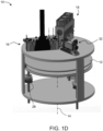
- FIGs. 1B-D Another representative and non-limiting example of a system 10 suitable for AM of an object according to some embodiments of the present invention is illustrated in FIGs. 1B-D .
- FIGs. 1B-D illustrate a top view ( FIG. 1B ), a side view ( FIG. 1C ) and an isometric view ( FIG. 1D ) of system 10.
- system 10 comprises a tray 12 and a plurality of inkjet printing heads 16 , each having one or more arrays of nozzles with respective one or more pluralities of separated nozzles.
- Tray 12 can have a shape of a disk or it can be annular. Non-round shapes are also contemplated, provided they can be rotated about a vertical axis.
- Printing heads 16 can be any of the printing heads described above with respect to system 110.
- Tray 12 and heads 16 are optionally and preferably mounted such as to allow a relative rotary motion between tray 12 and heads 16. This can be achieved by (i) configuring tray 12 to rotate about a vertical axis 14 relative to heads 16 , (ii) configuring heads 16 to rotate about vertical axis 14 relative to tray 12 , or (iii) configuring both tray 12 and heads 16 to rotate about vertical axis 14 but at different rotation velocities ( e.g ., rotation at opposite direction). While the embodiments below are described with a particular emphasis to configuration (i) wherein the tray is a rotary tray that is configured to rotate about vertical axis 14 relative to heads 16 , it is to be understood that the present application contemplates also configurations (ii) and (iii). Any one of the embodiments described herein can be adjusted to be applicable to any of configurations (ii) and (iii), and one of ordinary skills in the art, provided with the details described herein, would know how to make such adjustment.
- a direction parallel to tray 12 and pointing outwardly from axis 14 is referred to as the radial direction r
- a direction parallel to tray 12 and perpendicular to the radial direction r is referred to herein as the azimuthal direction ⁇
- a direction perpendicular to tray 12 is referred to herein is the vertical direction z.
- radial position refers to a position on or above tray 12 at a specific distance from axis 14.
- the term refers to a position of the head which is at specific distance from axis 14.
- the term corresponds to any point that belongs to a locus of points that is a circle whose radius is the specific distance from axis 14 and whose center is at axis 14.
- azimuthal position refers to a position on or above tray 12 at a specific azimuthal angle relative to a predetermined reference point.
- radial position refers to any point that belongs to a locus of points that is a straight line forming the specific azimuthal angle relative to the reference point.
- Tray 12 serves as a supporting structure for three-dimensional printing.
- the working area on which one or objects are printed is typically, but not necessarily, smaller than the total area of tray 12.
- the working area is annular.
- the working area is shown at 26.
- tray 12 rotates continuously in the same direction throughout the formation of object, and in some embodiments of the present invention tray reverses the direction of rotation at least once ( e.g., in an oscillatory manner) during the formation of the object.
- Tray 12 is optionally and preferably removable. Removing tray 12 can be for maintenance of system 10 , or, if desired, for replacing the tray before printing a new object.
- system 10 is provided with one or more different replacement trays (e.g., a kit of replacement trays), wherein two or more trays are designated for different types of objects (e.g., different weights) different operation modes (e.g. , different rotation speeds), etc.
- the replacement of tray 12 can be manual or automatic, as desired.
- system 10 comprises a tray replacement device 36 configured for removing tray 12 from its position below heads 16 and replacing it by a replacement tray (not shown).
- tray replacement device 36 is illustrated as a drive 38 with a movable arm 40 configured to pull tray 12 , but other types of tray replacement devices are also contemplated.
- FIGs. 2A-2C Exemplified embodiments for the printing head 16 are illustrated in FIGs. 2A-2C . These embodiments can be employed for any of the AM systems described above, including, without limitation, system 110 and system 10.
- FIGs. 2A-B illustrate a printing head 16 with one ( FIG. 2A ) and two ( FIG. 2B ) nozzle arrays 22.
- the nozzles in the array are preferably aligned linearly, along a straight line.
- the nozzle arrays are optionally and preferably can be parallel to each other.
- all arrays of the head can be fed with the same building material formulation, or at least two arrays of the same head can be fed with different building material formulations.
- all printing heads 16 are optionally and preferably oriented along the indexing direction with their positions along the scanning direction being offset to one another.
- all printing heads 16 are optionally and preferably oriented radially (parallel to the radial direction) with their azimuthal positions being offset to one another.
- the nozzle arrays of different printing heads are not parallel to each other but are rather at an angle to each other, which angle being approximately equal to the azimuthal offset between the respective heads.
- one head can be oriented radially and positioned at azimuthal position ⁇ 1
- another head can be oriented radially and positioned at azimuthal position ⁇ 2 .
- the azimuthal offset between the two heads is ⁇ 1 - ⁇ 2
- the angle between the linear nozzle arrays of the two heads is also ⁇ 1 - ⁇ 2 .
- system 10 comprises a support structure 30 positioned below heads 16 such that tray 12 is between support structure 30 and heads 16.
- Support structure 30 may serve for preventing or reducing vibrations of tray 12 that may occur while inkjet printing heads 16 operate.
- support structure 30 preferably also rotates such that support structure 30 is always directly below heads 16 (with tray 12 between heads 16 and tray 12 ).
- Tray 12 and/or printing heads 16 is optionally and preferably configured to move along the vertical direction z, parallel to vertical axis 14 so as to vary the vertical distance between tray 12 and printing heads 16.
- support structure 30 In configurations in which the vertical distance is varied by moving tray 12 along the vertical direction, support structure 30 preferably also moves vertically together with tray 12. In configurations in which the vertical distance is varied by heads 16 along the vertical direction, while maintaining the vertical position of tray 12 fixed, support structure 30 is also maintained at a fixed vertical position.
- the vertical motion can be established by a vertical drive 28.
- the vertical distance between tray 12 and heads 16 can be increased (e.g ., tray 12 is lowered relative to heads 16 ) by a predetermined vertical step, according to the desired thickness of the layer subsequently to be printed.
- the procedure is repeated to form a three-dimensional object in a layerwise manner.
- the operation of inkjet printing heads 16 and optionally and preferably also of one or more other components of system 10 , e.g., the motion of tray 12 , are controlled by a controller 20.
- the controller can have an electronic circuit and a non-volatile memory medium readable by the circuit, wherein the memory medium stores program instructions which, when read by the circuit, cause the circuit to perform control operations as further detailed below.
- Controller 20 can also communicate with a host computer 24 which transmits digital data pertaining to fabrication instructions based on computer object data, e.g., in a form of a Standard Tessellation Language (STL) or a StereoLithography Contour (SLC) format, Virtual Reality Modeling Language (VRML), Additive Manufacturing File (AMF) format, Drawing Exchange Format (DXF), Polygon File Format (PLY) or any other format suitable for Computer-Aided Design (CAD).
- STL Standard Tessellation Language
- SLC StereoLithography Contour
- VRML Virtual Reality Modeling Language
- AMF Additive Manufacturing File
- DXF Drawing Exchange Format
- PLY Polygon File Format
- CAD Computer-Aided Design
- the object data formats are typically structured according to a Cartesian system of coordinates.
- computer 24 preferably executes a procedure for transforming the coordinates of each slice in the computer object data from a Cartesian system of coordinates into a polar system of coordinates.
- Computer 24 optionally and preferably transmits the fabrication instructions in terms of the transformed system of coordinates.
- computer 24 can transmit the fabrication instructions in terms of the original system of coordinates as provided by the computer object data, in which case the transformation of coordinates is executed by the circuit of controller 20.
- the transformation of coordinates allows three-dimensional printing over a rotating tray.
- non-rotary systems with a stationary tray with the printing heads typically reciprocally move above the stationary tray along straight lines.
- the printing resolution is the same at any point over the tray, provided the dispensing rates of the heads are uniform.
- system 10 unlike non-rotary systems, not all the nozzles of the head points cover the same distance over tray 12 during at the same time.
- the transformation of coordinates is optionally and preferably executed so as to ensure equal amounts of excess material formulation at different radial positions.
- Representative examples of coordinate transformations according to some embodiments of the present invention are provided in FIGs. 3A-B , showing three slices of an object (each slice corresponds to fabrication instructions of a different layer of the objects), where FIG. 3A illustrates a slice in a Cartesian system of coordinates and FIG. 3B illustrates the same slice following an application of a transformation of coordinates procedure to the respective slice.
- controller 20 controls the voltage applied to the respective component of the system 10 based on the fabrication instructions and based on the stored program instructions as described below.
- controller 20 controls printing heads 16 to dispense, during the rotation of tray 12 , droplets of building material formulation in layers, such as to print a three-dimensional object on tray 12.
- System 10 optionally and preferably comprises a solidifying device 18 which can include one or more radiation sources, such as, but not limited to, an ultraviolet radiation source, visible radiation source or infrared radiation source, or other sources of electromagnetic radiation, or electron beam source, depending on the modeling material formulation being used.
- Radiation source can include any type of radiation emitting device, including, without limitation, light emitting diode (LED), digital light processing (DLP) system, resistive lamp and the like.
- Radiation source 18 serves for curing or solidifying the modeling material formulation. In various exemplary embodiments of the invention the operation of radiation source 18 is controlled by controller 20 which may activate and deactivate radiation source 18 and may optionally also control the amount of radiation generated by radiation source 18.
- system 10 optionally and preferably comprises an additional radiation 328 , as further detailed hereinabove.
- solidifying device 18 comprises a radiation source generating ultraviolet radiation, and radiation source 328 generates infrared radiation.
- system 10 further comprises one or more leveling devices 32 which can be manufactured as a roller or a blade.
- Leveling device 32 serves to straighten the newly formed layer prior to the formation of the successive layer thereon.
- leveling device 32 has the shape of a conical roller positioned such that its symmetry axis 34 is tilted relative to the surface of tray 12 and its surface is parallel to the surface of the tray. This embodiment is illustrated in the side view of system 10 ( FIG. 1C ).
- the conical roller can have the shape of a cone or a conical frustum.
- the opening angle of the conical roller is preferably selected such that is a constant ratio between the radius of the cone at any location along its axis 34 and the distance between that location and axis 14.
- This embodiment allows roller 32 to efficiently level the layers, since while the roller rotates, any point p on the surface of the roller has a linear velocity which is proportional ( e.g ., the same) to the linear velocity of the tray at a point vertically beneath point p.
- leveling device 32 is optionally and preferably controlled by controller 20 which may activate and deactivate leveling device 32 and may optionally also control its position along a vertical direction (parallel to axis 14 ) and/or a radial direction (parallel to tray 12 and pointing toward or away from axis 14.
- printing heads 16 are configured to reciprocally move relative to tray along the radial direction r . These embodiments are useful when the lengths of the nozzle arrays 22 of heads 16 are shorter than the width along the radial direction of the working area 26 on tray 12. The motion of heads 16 along the radial direction is optionally and preferably controlled by controller 20.
- Some embodiments contemplate the fabrication of an object by dispensing different material formulations from different arrays of nozzles (belonging to the same or different printing head). These embodiments provide, inter alia , the ability to select material formulations from a given number of material formulations and define desired combinations of the selected material formulations and their properties.
- the spatial locations of the deposition of each material formulation with the layer is defined, either to effect occupation of different three-dimensional spatial locations by different material formulations, or to effect occupation of substantially the same three-dimensional location or adjacent three-dimensional locations by two or more different material formulations so as to allow post deposition spatial combination of the material formulations within the layer, thereby to form a composite material formulation at the respective location or locations.
- Any post deposition combination or mix of modeling material formulations is contemplated. For example, once a certain material formulation is dispensed it may preserve its original properties. However, when it is dispensed simultaneously with another modeling material formulation or other dispensed material formulations which are dispensed at the same or nearby locations, a composite material formulation having a different property or properties to the dispensed material formulations is formed.
- the present embodiments thus enable the deposition of a broad range of material formulation combinations, and the fabrication of an object which may consist of multiple different combinations of material formulations, in different parts of the object, according to the properties desired to characterize each part of the object.
- FIG. 4 is a flowchart diagram of a method suitable for AM of a three-dimensional object according to various exemplary embodiments of the present invention. It is to be understood that, unless otherwise defined, the operations described hereinbelow can be executed either contemporaneously or sequentially in many combinations or orders of execution. Specifically, the ordering of the flowchart diagrams is not to be considered as limiting. For example, two or more operations, appearing in the following description or in the flowchart diagrams in a particular order, can be executed in a different order ( e.g ., a reverse order) or substantially contemporaneously. Additionally, several operations described below are optional and may not be executed.
- the method can be executed by an AM system (e.g ., system 110 or system 10 ) operated by a controller (e.g ., controller 152 or 20 ).
- the method begins at 400 and optionally and preferably proceeds to 401 at which at which computer object data that collectively pertain to a three-dimensional shape of the object are received.
- the data can be received by a data processor (e.g ., processor 154 or 24 ) operatively associated with the AM system.
- the data processor can access a computer-readable storage medium (not shown) and retrieve the data from the medium.
- the data processor can also generate the data, or a portion thereof, instead of, or in addition to, retrieving data from the storage medium, for example, by means of a computer aided design (CAD) or computer aided manufacturing (CAM) software.
- the computer object data typically include a plurality of slice data each defining a layer of the object to be manufactured.
- the data processor can transfer the data, or a portion thereof, to the controller of the AM system. Typically, but not necessarily, the controller receives the data on a slice-by-slice basis.
- the data can be in any data format known in the art, including, any of the aforementioned computer object data formats.
- the method proceeds to 402 at which a modeling material formulation containing a curable material which is a polyimide precursor that forms, upon exposure to a curing condition, a polyimide is dispensed to form a layer in a configured pattern corresponding to a shape of a slice of the object.
- the modeling material formulation containing the polyimide precursor can be any of the polyimide precursor-containing formulations described herein. Alternatively other material formulations containing polyimide precursors can be used.
- the viscosity of the polyimide precursor-containing formulation while being dispensed is from about 12 cP to about 18 cP, e.g., about 15 cP.
- the dispensing 402 is preferably at a temperature of from about 65 °C to about 75 °C or from about 66 °C to about 72 °C.
- the dispensing 402 is optionally and preferably executed to dispense the polyimide precursor-containing material formulation in droplets having an average weight of from about 50 ng to about 90 ng or from about 65 ng to about 85 ng. These embodiments are particularly useful when the dispensing 402 is by a printing head having a nozzle internal diameter of from about 24 ⁇ m to about 28 ⁇ m ( e.g., the aforementioned E1 printing head). Alternatively, the average droplets' weight can be from about 28 ng to about 38 ng or from about 30 ng to about 34 ng, e.g., about 32 ng.
- the dispensing 402 is by a printing head having a nozzle diameter of from about 18 ⁇ m to about 23 ⁇ m ( e.g., the aforementioned GEN4L printing head).
- These weights can be achieved by applying a voltage of from about 23 V to about 30 V to the printing head.
- the printing heads are optionally and preferably activated by pulses of alternating voltage.
- the dispensing comprises applying voltage at a frequency of from about 15 kHz to about 25 kHz or from 16 kHz to about 20 kHz, e.g., about 18 kHz to the printing head.
- the applied voltage can be at a frequency of from about 35 kHz to about 45 kHz or from 36 kHz to about 40 kHz, e.g., about 38 kHz.
- the pulse width of the pulsed voltage can be from about 5 ⁇ s to about 10 ⁇ s or from about 6 ⁇ s to about 9 ⁇ s or from about 6 ⁇ s to about 6.4 ⁇ s or from about 6.1 ⁇ s to about 6.3 ⁇ s, e.g., about 6.2 ⁇ s or about 8 ⁇ s.
- the dispensing of the polyimide precursor-containing formulation is executed in cycles, each having an active period during which the polyimide precursor-containing formulation is intermittently dispensed, and an idle period during which the polyimide precursor-containing formulation is not dispensed.
- the durations of the active period and the idle period typically vary depending on the printing head that is being used and may also depend on the formulation. For example, in experiments performed by the inventors it was found that when the dispensed formulation is a polyimide precursor-containing modeling formulation comprising a bismaleimide and a solvent as described herein at 80:20 weight ratio, then one possible duration of the active time for an E1 printing head is less than 5 minutes, e.g ., from about 1 to about 4.5 minutes, and the preferred duration of the active time for a GEN4L printing head is more than 15 minutes, e.g ., from about 15 to about 25 minutes, with optional idle period of 15 minutes or more. For prolonged idle time-periods (for example at least 15 or at least 20 minutes), a purging and/or wiping operation is optionally and preferably executed before recommencing the dispensing of the polyimide precursor-containing modeling formulation.
- ultraviolet radiation and infrared radiation are applied to the newly formed layer, preferably using two different radiation sources (e.g ., sources 324 and 328 or sources 18 and 328 ).
- the ultraviolet radiation serves for curing polyimide precursor-containing formulation and the infrared radiation serves for removing solvent from the layer.
- the infrared radiation can have either a broad or a narrow wavelength spectrum, in any of the near, short, mid, long or far infrared ranges, and is typically generated by one or more ceramic and/or halogen lamps. It was found by the present inventors that removal of solvent by directly irradiating the newly formed layer is advantageous and enhances the quality of the fabricated object.
- the present inventors found that a direct irradiation of the newly formed layer by infrared radiation can reduce the roughness of the object's surface, and also reduces a curling effect, since it reduces or eliminates the amount of trapped solvent between the layers and therefore reduces formation of internal stresses.
- the infrared radiation preferably scans the layer at least once, and in some embodiments a plurality of times, before dispensing a subsequent layer.
- the cooling system is switched off during the formation of a layer from the polyimide precursor-containing formulation. It was found by the inventors that this further reduces the risk of curling since the solidification of the polyimide precursor-containing formulation is typically accompanied by relatively high shrinkage.
- the method proceeds to 404 at which a purging operation is executed.
- the purging operation typically includes dispensing remnants of the formulation out of the printing heads at a dedicated location on the tray that is laterally displaced from the location at which the object is being built.
- the purging operation can optionally and preferably be accompanied by a wiping operation in which the orifice plate 121 of the printing head is wiped, for example, by a wiper blade or a squeegee (not shown).
- the time-period between successive purging operations typically varies depending on the printing head that is being used and may also depend on the formulation.
- the dispensed formulation is a polyimide precursor-containing modeling formulation comprising a bismaleimide and a solvent as described herein at 80:20 weight ratio
- the preferred time-period between successive purging operations for an E1 printing head is from about 3 minutes to about 5 minutes, e.g ., about 4 minutes
- the preferred time-period between successive purging operations for a GEN4L printing head is from about 14 minutes to about 61 minutes.
- the method optionally and preferably loops back to 401 to receive data for another slice.
- the method can loop back to 402 for form the next layer.
- the method further comprises dispensing a building material that comprises a support formulation, and, further optionally and preferably, the method further comprises removing the support material once it cures or solidifies.
- An object according to some embodiments of the present invention is such that at least a part or a portion thereof comprises a polyimide, as defined herein.
- the object may be such that several parts or portions thereof are made of a polyimide material, or such that is entirely made of a polyimide material.
- the polyimide material can be the same or different in the different parts or portions, and, for each part, portion or the entire object made of a polyimide material, the polyimide material can be the same or different within the portion, part or object. When different polyimide materials are used, they can differ in their chemical composition and/or mechanical properties.
- building material formulation “uncured building material”, “uncured building material formulation”, “building material” and other variations therefore, collectively describe the materials that are dispensed to sequentially form the layers, as described herein.
- This phrase encompasses uncured materials dispensed so as to form the object, namely, one or more uncured modeling material formulation(s), and uncured materials dispensed so as to form the support, namely uncured support material formulations.
- cured modeling material or "hardened modeling material” describes the part of the building material that forms the object, as defined herein, upon exposing the dispensed building material to curing, and, optionally, if a support material has been dispensed, also upon removal of the cured support material, as described herein.
- the cured modeling material can be a single cured material or a mixture of two or more cured materials, depending on the modeling material formulations used in the method, as described herein.
- cured modeling material or "cured modeling material formulation” can be regarded as a cured building material wherein the building material consists only of a modeling material formulation (and not of a support material formulation). That is, this phrase refers to the portion of the building material, which is used to provide the final object.
- modeling material formulation which is also referred to herein interchangeably as “modeling formulation”, “model formulation” “model material formulation” or simply as “formulation”, describes a part or all of the building material which is dispensed so as to form the object, as described herein.
- the modeling material formulation is an uncured modeling formulation (unless specifically indicated otherwise), which, upon exposure to a curing condition (e.g., curing energy), forms the object or a part thereof.
- a curing condition e.g., curing energy
- a modeling material formulation is formulated for use in three-dimensional inkjet printing and is able to form a three-dimensional object on its own, i . e ., without having to be mixed or combined with any other substance.
- An uncured building material can comprise one or more modeling formulations, and can be dispensed such that different parts of the object are made, upon curing, of different cured modeling formulations or different combinations thereof, and hence are made of different cured modeling materials or different mixtures of cured modeling materials.
- the formulations forming the building material comprise one or more curable materials, which, when exposed to a curing condition (e.g., curing energy), form hardened (cured) material.
- a curing condition e.g., curing energy
- a "curable material” is a compound (typically a monomeric or oligomeric compound, yet optionally a polymeric material) which, when exposed to a curing condition (e.g., curing energy), as described herein, solidifies or hardens to form a cured material.
- Curable materials are typically polymerizable materials, which undergo polymerization and/or cross-linking when exposed to a suitable curing condition (e.g., a suitable energy source).
- a curable material also encompasses materials which harden or solidify (cure) without being exposed to a curing energy, but rather to a curing condition (for example, upon exposure to a chemical reagent), or simply upon exposure to the environment.
- curable and “solidifyable” as used herein are interchangeable.
- the polymerization can be, for example, free-radical polymerization, cationic polymerization or anionic polymerization, and each can be induced when exposed to curing energy such as, for example, radiation, heat, etc., as described herein.
- a curable material is a photopolymerizable material, which polymerizes and/or undergoes cross-linking upon exposure to radiation, as described herein, and in some embodiments the curable material is a UV-curable material, which polymerizes and/or undergoes cross-linking upon exposure to UV radiation, as described herein.
- a curable material as described herein is a photopolymerizable material that polymerizes via photo-induced free-radical polymerization.
- the curable material is a photopolymerizable material that polymerizes via photo-induced cationic polymerization.
- a curable material can be a monomer, an oligomer or a short-chain polymer, each being polymerizable and/or cross-linkable as described herein.
- a curable material when exposed to a curing condition (e.g., radiation), it hardens (cured) by any one, or combination, of chain elongation and cross-linking.
- a curing condition e.g., radiation
- a curable material is a monomer or a mixture of monomers which can form a polymeric material upon a polymerization reaction, when exposed to curing energy at which the polymerization reaction occurs.
- curable materials are also referred to herein as monomeric curable materials.
- a curable material is an oligomer or a mixture of oligomers which can form a polymeric material upon a polymerization reaction, when exposed to curing energy at which the polymerization reaction occurs.
- curable materials are also referred to herein as oligomeric curable materials.
- a curable material whether monomeric or oligomeric or polymeric, can be a mono-functional curable material or a multi-functional curable material.
- a mono-functional curable material comprises one functional group that can undergo polymerization when exposed to curing energy (e.g., radiation).
- a multi-functional curable material comprises two or more, e.g., 2, 3, 4 or more, functional groups that can undergo polymerization when exposed to curing energy.
- Multi-functional curable materials can be, for example, di-functional, tri-functional or tetra-functional curable materials, which comprise 2, 3 or 4 groups that can undergo polymerization, respectively.
- the two or more functional groups in a multi-functional curable material are typically linked to one another by a linking moiety, as defined herein.
- the linking moiety is an oligomeric or polymeric moiety
- the multi-functional group is an oligomeric or polymeric multi-functional curable material.
- Multi-functional curable materials can undergo polymerization when subjected to curing energy and/or act as cross-linkers.
- an object is manufactured by dispensing a building material (uncured) that comprises two or more different modeling material formulations, each modeling material formulation from a different array of nozzles (belonging to the same or different printing heads) of the inkjet printing apparatus.
- the modeling material formulations are optionally and preferably deposited in layers during the same pass of the printing heads.
- the modeling material formulations and/or combination of formulations within the layer are selected according to the desired properties of the object, and as further described in detail hereinbelow.
- the modeling material of each voxel or voxel block, obtained upon curing is independent of the modeling material of a neighboring voxel or voxel block, obtained upon curing, such that each voxel or voxel block may result in a different model material and the new properties of the whole part are a result of a spatial combination, on the voxel level, of several different model materials.
- the expression "at the voxel level" is used in the context of a different material and/or properties, it is meant to include differences between voxel blocks, as well as differences between voxels or groups of few voxels.
- the properties of the whole part are a result of a spatial combination, on the voxel block level, of several different model materials.
- the dispensed building material comprises at least one modeling material that contains a curable material which, upon exposure to a curing condition, forms a polyimide.
- a curable material is also referred to herein as "a polyimide precursor" and the modeling formulation that comprises such a curable material is referred to herein as a polyimide precursor-containing formulation.
- Polyimide precursors typically include one or more imide moieties and one or more polymerizable moieties.
- BMIs are precursors of polyimides that are used for preparation of thermosetting materials.
- ⁇ , ⁇ -Bismaleimides feature two imide moieties which are linked to one another via a linking moiety and which further feature polymerizable moieties that undergo homopolymerization and/or copolymerization when exposed to UV irradiation, thermal energy and/or chemical catalysis, to thereby provide a cross-linked polyimide, as depicted in Scheme 1 below.
- the double bond of the maleimide end-group is highly electron deficient due to the adjacent electron-withdrawing acyl groups.
- low molecular weight bismaleimide precursors can undergo homo- and/or copolymerization at the carbon-carbon double bond to provide a crosslinked network.
- the unsaturated alkenyl group is a very reactive dienophile and, therefore, can undergo addition reactions such as Michael addition of amines (e.g., polyamines) and Diels-Adler addition of dienes.
- the obtained polyimide materials are thermosetting materials that are characterized by relative ease of processing and the ability to tailor specific rheological properties by controlling the molecular weight and possibly the chemical composition of the linking moiety. Additionally, the obtained polyimides have excellent retention of physical properties at high temperatures, in wet environments and in the presence of solvents and lubricating fluids.
- a polyimide precursor is other than a bis-allyl-nadi-imide compound.
- the polyimide precursor-containing formulation is devoid of (as defined herein) a bis-allyl-nadi-imide compound.
- the solvent is an organic solvent and in some embodiments it is an organic polar solvent.
- the additional curable material is a mono-functional acrylate or methacrylate ((meth)acrylate).
- Non-limiting examples include isobornyl acrylate (IBOA), isobornylmethacrylate, acryloyl morpholine (ACMO), phenoxyethyl acrylate, marketed by Sartomer Company (USA) under the trade name SR-339, urethane acrylate oligomer such as marketed under the name CN 131B, and any other acrylates and methacrylates usable in AM methodologies.
- IBOA isobornyl acrylate
- ACMO acryloyl morpholine
- SR-339 acryloyl morpholine
- urethane acrylate oligomer such as marketed under the name CN 131B
- any other acrylates and methacrylates usable in AM methodologies.
- the additional curable material is a multi-functional acrylate or methacrylate ((meth)acrylate).
- multi-functional (meth)acrylates include propoxylated (2) neopentyl glycol diacrylate, marketed by Sartomer Company (USA) under the trade name SR-9003, Ditrimethylolpropane Tetra-acrylate (DiTMPTTA), Pentaerythitol Tetra-acrylate (TETTA), and Dipentaerythitol Penta-acrylate (DiPEP), and an aliphatic urethane diacrylate, for example, such as marketed as Ebecryl 230.
- Non-limiting examples of multi-functional (meth)acrylate oligomers include ethoxylated or methoxylated polyethylene glycol diacrylate or dimethacrylate, ethoxylated bisphenol A diacrylate, polyethylene glycol-polyethylene glycol urethane diacrylate, a partially acrylated polyol oligomer, polyester-based urethane diacrylates such as marketed as CNN91.
- one or more of the modeling material formulation(s) further comprises an initiator, for promoting the hardening (solidification, curing) of the curable materials, for example, by initiating or promoting polymerization of the polymerizable curable materials.
- a concentration of a photoinitiator in a formulation containing same may range from about 0.1 to about 5 weight percents, or from about 1 to about 5 weight percents, including any intermediate value and subranges therebetween.
- one or more of the modeling material formulation(s) further comprises a curable or non-curable material that chemically interacts with the polyimide precursor (e.g., via Michael addition or Diels-Alder reaction, as described herein).
- a curable or non-curable material that chemically interacts with the polyimide precursor (e.g., via Michael addition or Diels-Alder reaction, as described herein).
- exemplary such material is a polyamine or a polyamine precursor.
- a modeling material formulation can further comprise one or more additional materials, which are referred to herein also as nonreactive materials.
- Such agents include, for example, surface active agents, stabilizers, antioxidants, fillers, pigments, dispersants, and/or impact modifying agents (toughening agents or toughness modifiers).
- the nonreactive agents can be independently included in one or all of the modeling material formulations.
- filler describes an inert material that modifies the properties of a polymeric material and/or adjusts a quality of the end products.
- the filler may be an inorganic particle, for example calcium carbonate, silica, and clay.
- Fillers may be added to the modeling formulation in order to reduce shrinkage during polymerization or during cooling, for example, to reduce the coefficient of thermal expansion, increase strength, increase thermal stability, reduce cost and/or adopt rheological properties. Nanoparticles fillers are typically useful in applications requiring low viscosity such as ink-jet applications.
- a modeling material formulation comprises a surface active agent.
- a surface-active agent may be used to reduce the surface tension of the formulation to the value required for jetting or for printing process, which is typically between 10 dyn/cm and 50 dyn/cm, for instance about 30 dyn/cm.
- An exemplary such agent is a silicone surface additive.
- Suitable stabilizers include, for example, thermal stabilizers, which stabilize the formulation at high temperatures.
- the modeling formulation comprises one or more pigments.
- the pigment's concentration is lower than 35%, or lower than 25 % or lower than 15 %, by weight.
- the pigment may be a white pigment.
- the pigment may be an organic pigment or an inorganic pigment, or a metal pigment or a combination thereof.
- the modeling formulation further comprises a dye.
- combinations of white pigments and dyes are used to prepare colored cured materials.
- the dye may be any of a broad class of solvent soluble dyes.
- Some non-limiting examples are azo dyes which are yellow, orange, brown and red; anthraquinone and triarylmethane dyes which are green and blue; and azine dye which is black.
- one or more of the modeling material formulations comprises a toughening agent.
- Non-limiting examples of toughening agents include elastomeric materials.
- Representative examples include, without limitation, natural rubber, butyl rubber, polyisoprene, polybutadiene, polyisobutylene, ethylene-propylene copolymer, styrene-butadiene - styrene triblock rubber, random styrene-butadiene rubber, styrene-isoprene-styrene triblock rubber, styrene-ethylene/butylene-styrene copolymer, styrene-ethylene/propylene-styrene copolymer, ethylene- propylene- diene terpolymers, ethylene-vinyl acetate and nitrile rubbers.
- Preferred agents are elastomers such as polybutadienes.
- Toughening agents such as elastomeric materials can be added to the formulation by incorporating in a modeling material formulation an
- a concentration of elastomeric materials may range from about 0.10 phr to about 10 phr, or from about 0.1 phr to about 5 phr, relative to the weight of the formulation containing same.
- a concentration of elastomeric materials may alternatively range from about 0.1 % to about 20 %, by weight, of the total weight of a formulation containing same.
- impact modifying agents such as, for example, carbon fibers, carbon nanotubes, glass fibers, aramid Kevlar, polyparaphenylene benzobisoxazole Zylon, and other polar and nonpolar impact modifiers, are also contemplated.
- Photo-curing can be done by UV sources, such as Xe lamp, mercury lamp, LED UV lamp, intense pulsed light (IPL), or UV laser, with intensity of up to 2000 J/cm 2 in the UV-VIS spectral range.
- UV sources such as Xe lamp, mercury lamp, LED UV lamp, intense pulsed light (IPL), or UV laser, with intensity of up to 2000 J/cm 2 in the UV-VIS spectral range.
- Thermal curing can be done by UV-VIS radiation or conduction, for example by using infrared lamp, and/or heating of the printed surface by heating of the printing tray or the environment in the chamber.
- Thermal curing can be enhanced by addition of peroxide catalyst, such as dicumyl peroxide (added at 0.01 - 2 wt.%) or thermo epoxy catalyst, such as tertiary amines, imidazoles and alcohols.
- peroxide catalyst such as dicumyl peroxide (added at 0.01 - 2 wt.%)
- thermo epoxy catalyst such as tertiary amines, imidazoles and alcohols.
- compositions, method or structure may include additional ingredients, steps and/or parts, but only if the additional ingredients, steps and/or parts do not materially alter the basic and novel characteristics of the claimed composition, method or structure.
- a compound or “at least one compound” may include a plurality of compounds, including mixtures thereof.
- range format is merely for convenience and brevity and should not be construed as an inflexible limitation on the scope of the invention. Accordingly, the description of a range should be considered to have specifically disclosed all the possible subranges as well as individual numerical values within that range. For example, description of a range such as from 1 to 6 should be considered to have specifically disclosed subranges such as from 1 to 3, from 1 to 4, from 1 to 5, from 2 to 4, from 2 to 6, from 3 to 6 etc., as well as individual numbers within that range, for example, 1, 2, 3, 4, 5, and 6. This applies regardless of the breadth of the range.
- (meth)acrylic encompasses acrylic and methacrylic compounds.
- linking moiety or “linking group” describes a group that connects two or more moieties or groups in a compound.
- a linking moiety is typically derived from a bi- or tri-functional compound, and can be regarded as a bi- or tri-radical moiety, which is connected to two or three other moieties, via two or three atoms thereof, respectively.
- linking moieties include a hydrocarbon moiety or chain, optionally interrupted by one or more heteroatoms, as defined herein, and/or any of the chemical groups listed below, when defined as linking groups.
- end group When a chemical group is referred to herein as "end group" it is to be interpreted as a substituent, which is connected to another group via one atom thereof.
- hydrocarbon collectively describes a chemical group composed mainly of carbon and hydrogen atoms.
- a hydrocarbon can be comprised of alkyl, alkene, alkyne, aryl, and/or cycloalkyl, each can be substituted or unsubstituted, and can be interrupted by one or more heteroatoms.
- the number of carbon atoms can range from 2 to 20, and is preferably lower, e.g., from 1 to 10, or from 1 to 6, or from 1 to 4.
- a hydrocarbon can be a linking group or an end group.
- Bisphenol A is an example of a hydrocarbon comprised of 2 aryl groups and one alkyl group.
- amine describes both a -NR'R” group and a -NR'- group, wherein R' and R" are each independently hydrogen, alkyl, cycloalkyl, aryl, as these terms are defined hereinbelow.
- the amine group can therefore be a primary amine, where both R' and R" are hydrogen, a secondary amine, where R' is hydrogen and R" is alkyl, cycloalkyl or aryl, or a tertiary amine, where each of R' and R" is independently alkyl, cycloalkyl or aryl.
- R' and R" can each independently be hydroxyalkyl, trihaloalkyl, cycloalkyl, alkenyl, alkynyl, aryl, heteroaryl, heteroalicyclic, amine, halide, sulfonate, sulfoxide, phosphonate, hydroxy, alkoxy, aryloxy, thiohydroxy, thioalkoxy, thioaryloxy, cyano, nitro, azo, sulfonamide, carbonyl, C-carboxylate, O-carboxylate, N-thiocarbamate, O-thiocarbamate, urea, thiourea, N-carbamate, O-carbamate, C-amide, N-amide, guanyl, guanidine and hydrazine.
- amine is used herein to describe a -NR'R" group in cases where the amine is an end group, as defined hereinunder, and is used herein to describe a -NR'- group in cases where the amine is a linking group or is or part of a linking moiety.
- alkyl describes a saturated aliphatic hydrocarbon including straight chain and branched chain groups.
- the alkyl group has 1 to 30, or 1 to 20 carbon atoms.
- the alkyl group may be substituted or unsubstituted.
- Substituted alkyl may have one or more substituents, whereby each substituent group can independently be, for example, hydroxyalkyl, trihaloalkyl, cycloalkyl, alkenyl, alkynyl, aryl, heteroaryl, heteroalicyclic, amine, halide, sulfonate, sulfoxide, phosphonate, hydroxy, alkoxy, aryloxy, thiohydroxy, thioalkoxy, thioaryloxy, cyano, nitro, azo, sulfonamide, C-carboxylate, O-carboxylate, N-thiocarbamate, O-thiocarbamate, urea, thiourea, N-carbamate, O-carbamate, C-amide, N-amide, guanyl, guanidine and hydrazine.
- substituent group can independently be, for example, hydroxyalkyl, trihaloalkyl, cycloalkyl
- the alkyl group can be an end group, as this phrase is defined hereinabove, wherein it is attached to a single adjacent atom, or a linking group, as this phrase is defined hereinabove, which connects two or more moieties via at least two carbons in its chain.
- a linking group it is also referred to herein as "alkylene” or "alkylene chain”.
- hydrophilic group a C(1-4) alkyl, substituted by a hydrophilic group, as defined herein, is included under the phrase "hydrophilic group" herein.
- Alkene and Alkyne are an alkyl, as defined herein, which contains one or more double bond or triple bond, respectively.
- cycloalkyl describes an all-carbon monocyclic ring or fused rings ( i . e ., rings which share an adjacent pair of carbon atoms) group where one or more of the rings does not have a completely conjugated pi-electron system. Examples include, without limitation, cyclohexane, adamantine, norbornyl, isobornyl, and the like.
- the cycloalkyl group may be substituted or unsubstituted.
- Substituted cycloalkyl may have one or more substituents, whereby each substituent group can independently be, for example, hydroxyalkyl, trihaloalkyl, cycloalkyl, alkenyl, alkynyl, aryl, heteroaryl, heteroalicyclic, amine, halide, sulfonate, sulfoxide, phosphonate, hydroxy, alkoxy, aryloxy, thiohydroxy, thioalkoxy, thioaryloxy, cyano, nitro, azo, sulfonamide, C-carboxylate, O-carboxylate, N-thiocarbamate, O-thiocarbamate, urea, thiourea, N-carbamate, O-carbamate, C-amide, N-amide, guanyl, guanidine and hydrazine.
- substituent group can independently be, for example, hydroxyalkyl, trihaloalkyl, cyclo
- the cycloalkyl group can be an end group, as this phrase is defined hereinabove, wherein it is attached to a single adjacent atom, or a linking group, as this phrase is defined hereinabove, connecting two or more moieties at two or more positions thereof.
- Cycloalkyls of 1-6 carbon atoms, substituted by two or more hydrophilic groups, as defined herein, is included under the phrase "hydrophilic group" herein.
- heteroalicyclic describes a monocyclic or fused ring group having in the ring(s) one or more atoms such as nitrogen, oxygen and sulfur.
- the rings may also have one or more double bonds. However, the rings do not have a completely conjugated pi-electron system.
- Representative examples are piperidine, piperazine, tetrahydrofuran, tetrahydropyrane, morpholino, oxalidine, and the like.
- the heteroalicyclic may be substituted or unsubstituted.
- Substituted heteroalicyclic may have one or more substituents, whereby each substituent group can independently be, for example, hydroxyalkyl, trihaloalkyl, cycloalkyl, alkenyl, alkynyl, aryl, heteroaryl, heteroalicyclic, amine, halide, sulfonate, sulfoxide, phosphonate, hydroxy, alkoxy, aryloxy, thiohydroxy, thioalkoxy, thioaryloxy, cyano, nitro, azo, sulfonamide, C-carboxylate, O-carboxylate, N-thiocarbamate, O-thiocarbamate, urea, thiourea, O-carbamate, N-carbamate, C-amide, N-amide, guanyl, guanidine and hydrazine.
- the heteroalicyclic group can be an end group, as this phrase is defined hereinabove, where it is attached to a single adjacent atom, or a linking group, as this phrase is defined hereinabove, connecting two or more moieties at two or more positions thereof.
- a heteroalicyclic group which includes one or more of electron-donating atoms such as nitrogen and oxygen, and in which a numeral ratio of carbon atoms to heteroatoms is 5:1 or lower, is included under the phrase "hydrophilic group" herein.
- aryl describes an all-carbon monocyclic or fused-ring polycyclic ( i . e ., rings which share adjacent pairs of carbon atoms) groups having a completely conjugated pi-electron system.
- the aryl group may be substituted or unsubstituted.
- Substituted aryl may have one or more substituents, whereby each substituent group can independently be, for example, hydroxyalkyl, trihaloalkyl, cycloalkyl, alkenyl, alkynyl, aryl, heteroaryl, heteroalicyclic, amine, halide, sulfonate, sulfoxide, phosphonate, hydroxy, alkoxy, aryloxy, thiohydroxy, thioalkoxy, thioaryloxy, cyano, nitro, azo, sulfonamide, C-carboxylate, O-carboxylate, N-thiocarbamate, O-thiocarbamate, urea, thiourea, N-carbamate, O-carbamate, C-amide, N-amide, guanyl, guanidine and hydrazine.
- substituent group can independently be, for example, hydroxyalkyl, trihaloalkyl, cycloalkyl
- the aryl group can be an end group, as this term is defined hereinabove, wherein it is attached to a single adjacent atom, or a linking group, as this term is defined hereinabove, connecting two or more moieties at two or more positions thereof.
- heteroaryl describes a monocyclic or fused ring ( i . e ., rings which share an adjacent pair of atoms) group having in the ring(s) one or more atoms, such as, for example, nitrogen, oxygen and sulfur and, in addition, having a completely conjugated pi-electron system.
- heteroaryl groups include pyrrole, furan, thiophene, imidazole, oxazole, thiazole, pyrazole, pyridine, pyrimidine, quinoline, isoquinoline and purine.
- the heteroaryl group may be substituted or unsubstituted.
- Substituted heteroaryl may have one or more substituents, whereby each substituent group can independently be, for example, hydroxyalkyl, trihaloalkyl, cycloalkyl, alkenyl, alkynyl, aryl, heteroaryl, heteroalicyclic, amine, halide, sulfonate, sulfoxide, phosphonate, hydroxy, alkoxy, aryloxy, thiohydroxy, thioalkoxy, thioaryloxy, cyano, nitro, azo, sulfonamide, C-carboxylate, O-carboxylate, N-thiocarbamate, O-thiocarbamate, urea, thiourea, O-carbamate, N-carbamate, C-amide, N-amide, guanyl, guanidine and hydrazine.
- substituent group can independently be, for example, hydroxyalkyl, trihaloalkyl, cycloalkyl
- the heteroaryl group can be an end group, as this phrase is defined hereinabove, where it is attached to a single adjacent atom, or a linking group, as this phrase is defined hereinabove, connecting two or more moieties at two or more positions thereof.
- Representative examples are pyridine, pyrrole, oxazole, indole, purine and the like.
- halide and "halo" describes fluorine, chlorine, bromine or iodine.
- haloalkyl describes an alkyl group as defined above, further substituted by one or more halide.
- dithiosulfide refers to a -S-SR' end group or a -S-S- linking group, as these phrases are defined hereinabove, where R' is as defined herein.
- phosphinyl describes a -PR'R" end group or a -PR'- linking group, as these phrases are defined hereinabove, with R' and R" as defined hereinabove.
- hydroxyl describes a -OH group.
- alkoxy describes both an -O-alkyl and an -O-cycloalkyl group, as defined herein.
- aryloxy describes both an -O-aryl and an -O-heteroaryl group, as defined herein.
- thiohydroxy describes a -SH group.
- thioalkoxy describes both a -S-alkyl group, and a -S-cycloalkyl group, as defined herein.
- thioaryloxy describes both a -S-aryl and a -S-heteroaryl group, as defined herein.
- hydroxyalkyl is also referred to herein as "alcohol”, and describes an alkyl, as defined herein, substituted by a hydroxy group.
- nitro describes an -NO 2 group.
- peroxo describes an -O-OR' end group or an -O-O- linking group, as these phrases are defined hereinabove, with R' as defined hereinabove.
- carboxylate as used herein encompasses C-carboxylate and O-carboxylate.
- a carboxylate can be linear or cyclic.
- R' and the carbon atom are linked together to form a ring, in C-carboxylate, and this group is also referred to as lactone.
- R' and O are linked together to form a ring in O-carboxylate.
- Cyclic carboxylates can function as a linking group, for example, when an atom in the formed ring is linked to another group.
- a thiocarboxylate can be linear or cyclic.
- R' and the carbon atom are linked together to form a ring, in C-thiocarboxylate, and this group is also referred to as thiolactone.
- R' and O are linked together to form a ring in O-thiocarboxylate.
- Cyclic thiocarboxylates can function as a linking group, for example, when an atom in the formed ring is linked to another group.
- carboxylate as used herein encompasses N-carbamate and O-carbamate.
- a carbamate can be linear or cyclic.
- R' and the carbon atom are linked together to form a ring, in O-carbamate.
- R' and O are linked together to form a ring in N-carbamate.
- Cyclic carbamates can function as a linking group, for example, when an atom in the formed ring is linked to another group.
- carboxylate as used herein encompasses N-carbamate and O-carbamate.
- thiocarbamate encompasses N-thiocarbamate and O-thiocarbamate.
- Thiocarbamates can be linear or cyclic, as described herein for carbamates.
- dithiocarbamate encompasses S-dithiocarbamate and N-dithiocarbamate.
- amide as used herein encompasses C-amide and N-amide.
- An amide can be linear or cyclic.
- R' and the carbon atom are linked together to form a ring, in C-amide, and this group is also referred to as lactam.
- Cyclic amides can function as a linking group, for example, when an atom in the formed ring is linked to another group.
- hydrozine describes a -NR'-NR"R′′′ end group or a -NR'-NR"- linking group, as these phrases are defined hereinabove, with R', R", and R′′′ as defined herein.
- alkylene glycol describes a -O-[(CR'R") z -O] y -R′′′ end group or a -O-[(CR'R") z -O] y - linking group, with R', R" and R′′′ being as defined herein, and with z being an integer of from 1 to 10, preferably, from 2 to 6, more preferably 2 or 3, and y being an integer of 1 or more.
- R' and R" are both hydrogen.
- z is 2 and y is 1, this group is ethylene glycol.
- z is 3 and y is 1, this group is propylene glycol.
- y 2-4, the alkylene glycol is referred to herein as oligo(alkylene glycol).
- BMI-based ink was prepared by dissolving 80 wt. % BMI oligomer, BMI-689 (Designer Molecules Inc.), in n-Hexyl Acetate, 99 % (Alfa Aesar) with the addition of free radical photoinitiators as follows: 2 wt.% of Irgacure 819 (BASF) and 1 wt.% Irgacure TPO-L (BASF).
- the viscosity of BMI-based ink was measured by Rolling-ball viscometer (Lovis 2000 M/ME, Anton Paar) with thermoregulation by water circulation (F12, Julabo).
- the surface tension of the BMI solutions was measured by Sigma Force Tensiometer, model 700/701, by Biolin Scientific, using the du Noüy ring method.
- Dynamic surface tension of the BMI-based ink was measured using Bubble Pressure Tensiometer, BP100 by KRUSS.
- TGA 550 by TA Instruments, was used for thermogravimetric analysis. Hexyl acetate 100%, was heated in an aluminum crucible of 5.6 mm diameter, in a ramp of 20 °C/min to the each of the following temperatures: 25 °C, 55 °C, 65 °C, 70 °C and 75 °C, with isothermal dwell time of 15 minutes at each temperature. The weight loss per temperature was calculated from the isothermal part only.
- the printing trials were performed in single jetting mode, with a layer thickness of 28 ⁇ m.
- the physical properties that define the capability of jetting are the surface tension, density, bulk modulus, speed of sound, viscosity of the formulation and the dimensions of the nozzle.
- the drop formation process has three main parts: (i) detachment from the orifice plate, (ii) flight, and (iii) impact on the surface.
- materials with high vapor pressure such as certain solvents
- the effect of evaporation needs to be examined.
- the vapor pressure increase and thereby lead to a dramatic evaporation.
- the effect of evaporation can change the meniscus position and to result in bad jetting, wetting and nozzle failure.
- We ⁇ dv 2 ⁇ where ⁇ is the surface tension.
- Oh is independent on the driven condition. If Oh value is too high (Oh > ⁇ 1) then viscous forces will prevent the separation of a drop, while if it is too low (Oh ⁇ ⁇ 0.1), the jet will form large number of satellite droplets.
- the jet must possess enough kinetic energy to be ejected from the nozzle, such that Oh > 2/Re, and it is also desirable to avoid splashing of the drop on impact with the substrate such that Oh ⁇ 20/Re 5/4 [Inkjet Printing of Functional and Structural Materials: Fluid Property Requirements, Feature Stability, and Resolution; Brian Derby; Annual Review of Materials Research 2010 40:1, 395-414].
- An exemplary formulation for inkjet printing optionally and preferably has a viscosity of 14-16 mPa, and a surface tension of 27-32 dyn/cm at the jetting temperature.
- a polyimide precursor-containing formulation comprising a bismaleimide and a solvent as described herein at 80:20 weight ratio has a viscosity of 120 mPa at room temperature, which is typically too high for jetting. Viscosity decrease can be achieved by one of the following ways: diluting with additional solvent, which requires higher energy input for drying the excess solvent, after a layer of the formulation is deposited on the receiving medium, or increasing the jetting temperature, which may result in solvent evaporation within the printing head.
- thermogravimetric analysis was performed of hexyl acetate as a function of temperature.
- FIG. 5A presents a plot showing the weight loss of the hexyl acetate, as a function of temperature, measured by ( WL TGA ). The measurement was performed at heating rate of 20 °C/minute with liquid surface area of 24 mm 2 .
- the weight loss in the head's nozzle in ng per minute is shown in FIG. 5C .
- the weight loss per time is proportional to the surface between the air and the liquid. Therefore the weight loss in the nozzle can be regarded as: WL NOZZLE ⁇ WL TGA A NOZZLE A TGA ⁇ WL TGA 8.7 ⁇ 10 ⁇ 5 .
- This force is in the order of 2 ⁇ rd ⁇ and the corresponding pressure is 2 d ⁇ / r.
- the nozzle radius for E1 is about 20 ⁇ m, indicating that the pressure can be decreased by about 6.05 KPa for small contact angle ⁇ c , thereby decreasing the evaporation rate by a factor of 2 and even higher.
- FIG. 6 shows the static surface tension and the viscosity of the BMI-based ink as a function of temperature.
- the static surface tension shows linear correlation with temperature with a slope of -0.0743 and intercept of 33.611. Thus, values of surface tension at higher temperatures can be extrapolated.
- the viscosity is a logarithmic function of reciprocal temperature, and hence viscosity values at relevant working range can be extrapolated, as shown in FIGs. 7A and 7B , respectively.
- the temperatures which allow the desired jetting viscosity are 68-72 °C.
- the corresponding static surface tension is 28.5-28.3 dyn/cm, which can be calculated from the linear fit at FIG. 6 .
- the corresponding weight loss is 2.5-3.3 wt. %, as can be seen from FIG. 5A .
- This mass loss which results from solvent evaporation, has a negligible effect on viscosity of the ink within the printing head.
- FIGs. 8A and 8B present the data obtained in measurements of the density and sound velocity, respectively, of the BMI-based ink formulation as a function of temperature.
- Jetting stability tests were conducted according to some embodiments of the present invention the following instruments were used: a jetting station comprising a motorized magnification camera, a light source (synchronize with fire), a balance device, a 3D inkjet printing system with GEN4L or E1 inkjet printing head, an ink feed system, a vacuum pump and supported electronics (OCB, OHDB and MSC), and software for controlling and analysis. Additional experiments were performed using a three-dimensional printing system.
- the magnification camera was used for on-the-fly drop analysis and for identifying wetting of the printing head nozzle.
- the balance device was used to measure the average drop weight. Density measurements were used to evaluate the drop volume.
- the control and analysis software was used for extracting the drop velocity per nozzle along the printing head at 1 mm from the printing head (the typical distance between the printing head and the tray), the number of good nozzles, and the drop weight at various jetting parameters - voltage frequency and pulse shape.
- the ligament length and the formation of satellites were also examined in cases where these were found critical for printing quality. Stability of jetting and the velocity typically determine the drop placement.
- FIG. 9 shows the number of active nozzles as a function of the time during a jetting stability test conducted on the E1 printing head.
- the wetting blocked the nozzles of the E1 printing head, after about 4 minutes of operation.
- a cycle of purging and wiping was therefore performed every 4 minutes of operation.
- FIGs. 10A and 10B are images of jetting captures at the beginning ( FIG. 10A ) and end ( FIG. 10B ) of a stability test conducted on the E1 printing head at a voltage of 30 V, pulse width of 8 ⁇ s and frequency of 18 kHz.
- the orifice plate (marked by an arrow), is clear and non-wetted.
- a large puddle on the orifice plate was observed.
- FIGs. 11A and 11B show contact angle measurements at the surface of E1 printing head ( FIG. 11A ) and the Gen4L printing head ( FIG. 11B ).
- the mean contact angle for the E1 printing head was 7.6 ⁇ 2.2° and the mean contact angle for the GEN4L printing head was 50.8 ⁇ 0.3°. It is noted that at the typical printing temperatures (about 70 °C) the saturation vapor pressure is smaller than the equilibrium vapor pressure by about four orders of magnitudes for both contact angles. The effect of saturation vapor pressure is therefore negligible.
- FIGs. 12A and 12B are images of jetting captures at the beginning ( FIG. 12A ) and end ( FIG. 12B ) of a stability test conducted on the GEN4L printing head at a voltage of 28.35V, pulse width of 6.2 ⁇ s and frequency of 38 kHz. As shown this printing head demonstrates stable printing with no significant nozzle failure with time.
- the jetting stability for this printing head was tested by cycles, wherein each cycle included jetting (1 sec on 1 sec off) for duration of about 5 min, followed by idle time of about 16 min, followed by jetting cycles for 9 minutes.
- the waveform (amplitude, frequency and pulse width) of the voltage applied to the printing head, the vacuum pressure, the time between purges or wipes, the idle period were varied.
- FIG. 13A shows the drop velocity as a function of the pulse width
- FIG. 13B shows the drop velocity at each nozzle at pulse width of 6.2 ⁇ s
- FIG. 13C shows the drop weight as a function of the pulse width. Stability was observed at a pulse width of about 6.2 ⁇ s.
- FIGs. 14A and 14B shows the average drop weight ( FIG. 14A ) drop velocity ( FIG. 14B ) as a function of the applied voltage at a frequency of 38 kHz
- FIG. 14C shows the average drop velocity at each nozzle at 28.33 V and 30.65 V. Extrapolating the velocity at 26.4 V, assuming linear dependent, results in a velocity of about 10.14 m/s.
- the high velocity is due to the relatively high viscosity of 15.159 cP. High velocity may be advantageous since it reduces the likelihood of wetting.
- a polyimide precursor-containing modeling formulation comprising a bismaleimide and a solvent as described herein at 80:20 weight ratio
- preferred printing parameters suitable for printing of using a printing head having an nozzle diameter of from about 24 ⁇ m to about 28 ⁇ m are listed in Table 1, below
- preferred printing parameters suitable for printing using a printing head having a nozzle diameter of from about 18 ⁇ m to about 23 ⁇ m are listed in Table 2, below.
- Table 1 Parameter preferred value tolerance T [ 0 C] 68 ⁇ 2 Viscosity [cP] 15 ⁇ 2 Surface tension [dyn/cm] 28.3 Density [g/cm 3 ] 0.93 ⁇ 0.03 target Drop weight [ng] 81.73- 70.8 ⁇ 2 Drop velocity [m/s] 9.8-8.4 ⁇ 1 Voltage at target drop weight [V] 28-25 ⁇ 2 V Pulse width [usec] 8 ⁇ 0.3 usec Fire frequency [KHz] 18 ⁇ 0.5KHz jetting over time ⁇ 5 > time between Wiping Jetting after idle time [min] 0 > time between Wiping Wiping frequency [min] 4 ⁇ 1 minutes
- FIG. 15A shows the printed sheet right after printing, still on glass substrate
- FIG. 15B shows the Polyimide sheet after thermal post cure at 150°C for 1 hour
- FIG. 15C shows the back side of the printed sheet, showing cracks and delamination between layers.
- the surface of the printed sheet has very high roughness, with crater-like texture resulting from solvent evaporation. After thermal post treatment the printed sheet developed curling, as a result of internal stresses. These stresses were the result of trapped solvent which did not evaporate properly. Moreover, delamination between printed layers was observed on the bottom part of the sheet ( FIG. 15C ).
- the ambient temperature within the printing zone increased with time, which is equivalent to the number of layers, due to the heating effect of the IR lamp.
- the first printed layers bottom part of the sheet
- the thermal post treatment was applied to complete conversion of the maleimide groups, leading to improved mechanical properties and to sinter the silver nanoparticles.
- the electrical conductivity of the printed conductive tracks was measured prior and after the thermal post treatment.
- the tracks were not conductive prior the treatment and conductive after the treatment.
- This experiment demonstrates the ability to print printed circuit boards and other 3D objects containing electrically conductive tracks, in one print.
- FIGs. 16A and 16B are images of a two 3D objects printed in this trial: a 69 ⁇ 11 ⁇ 1.5 mm micro-tensile dog bone ( FIG. 16A ), and a 10 ⁇ 10 ⁇ 10 mm pyramid ( FIG. 16B ).
- the printed objects were solid, dry and non-tacky to touch.
- This scan with IR lamp after the dispensing of each layer improved the surface of the printed objects, and eliminated the crater-like roughness, cracks and delamination.
- the efficiency of the solvent drying by infrared radiation was investigated by printing polyimide samples using different types and numbers of IR sources, and employing different numbers of scans (0, 4, and 8, in the present Trial).
- the surface temperature during printing was monitored by an IR sensor as a sampling rate of 100 Hz.
- Printed samples were weighted with an analytical balance, and TGA was performed in temperature ramp mode and isotherm mode (at 160 °C).
- the printer used was a modified Stratasys Connex500 TM printer with E1 printing heads. The printer was used to print bars 35 ⁇ 10 ⁇ 3 mm, in dimensions.
- the number of slices was 85.
- the tray temperature was about 90°C
- the printing head jetting temperature was about 70°C
- the printing mode was single jetting mode with 2 UV lamps operated at 100% power
- purging was executed every 240 seconds (to keep orifice plate from wetting)
- the cooling fans were not operated (to reduce or prevent curling and detachment from the tray).
- Examples of the printed samples are shown in FIG. 17 .
- FIG. 18 shows TGA results of samples printed with different IR sources (1 FIR lamp, 1 NIR lamp, and 2 NIR lamps) with 0 or 8 scanning performed after each slice.
- the weight loss was recorded during isothermal dwell at 160°C for 120 minutes.
- the temperature of 160°C was selected for the isothermal dwell, since at this temperature pure BMI has no mass loss, and the only volatile component is the hexyl acetate solvent.
- all samples show mass loss, even at the higher power irradiation (2 NIR lamps, 8 scans) during printing. The highest mass loss is for the 0 scans experiment.
- the NIR lamp was slightly more effective than the IR lamp, after 8 scans.
- the lowest residual solvent content was obtained with 8 scans with 2 NIR lamps.
- FIGs. 19A-I show the temperature of the uppermost layer as a function of the IR sampling count (sampling rate was, as sated, 100Hz).
- FIGs. 19A-I show the temperature of the uppermost layer when irradiated with the FIR lamp ( FIGs. 19A-C ), the NIR lamp ( FIGs. 19D-F ), and the two NIR lamps ( FIGs. 19G-I ), according to the 0 scan protocol ( FIGs. 19A , 19D and 19G ), the 4 scan protocol ( FIGs. 19B , 19E and 19H ), and the 8 scan protocol ( FIGs. 19C , 19F and 19I ).
- the dips in FIGs. 19A-I correspond to purging operations.
- the surface temperature during printing of the upper layer of the samples was not affected by the type of IR lamp or the number of scans.
- the final temperature with both types of lamp reached about 140°C.
- a higher number of scans resulted in longer time between the slices, and more effective evaporation.
- the IR power is doubled, as in the case of 2 NIR lamps ( FIGs 19G-I )
- a higher photon fluency results in higher surface temperature, which reaches up to 200°C.
- the higher surface temperature, combined with a high number of scans e.g ., the 8 scans in FIG. 19I ) resulted in the most effective drying (0.848% loss, in the present trial).
Landscapes
- Chemical & Material Sciences (AREA)
- Engineering & Computer Science (AREA)
- Materials Engineering (AREA)
- Manufacturing & Machinery (AREA)
- Physics & Mathematics (AREA)
- Mechanical Engineering (AREA)
- Optics & Photonics (AREA)
- Health & Medical Sciences (AREA)
- Toxicology (AREA)
- Medicinal Chemistry (AREA)
- Polymers & Plastics (AREA)
- Organic Chemistry (AREA)
- Chemical Kinetics & Catalysis (AREA)
- Microelectronics & Electronic Packaging (AREA)
Claims (15)
- Verfahren (400) zur additiven Herstellung eines dreidimensionalen Objekts (112) durch Tintenstrahldruck, wobei das Verfahren (400) umfasst:Abgeben (402) einer Modelliermaterialformulierung aus einem ersten Array (122) von Düsen einer Tintenstrahlvorrichtung (114), wobei die Modelliermaterialformulierung einen Polyimidvorläufer enthält, der bei Aussetzung gegenüber einer Härtungsbedingung ein Polyimid bildet, in einem konfigurierten Muster, das einer Form einer Scheibe des Objekts entspricht, wodurch eine Schicht des Objekts (112) gebildet wird;Anwenden (403) von Ultraviolettstrahlung bzw. Infrarotstrahlung von zwei unterschiedlichen Strahlungsquellen (324, 328) auf die besagte Schicht, wobei das besagte Anwenden (403) der besagten Infrarotstrahlung durch Durchführen einer Vielzahl von Scans der besagten Infrarotstrahlung über die besagte Schicht erfolgt; undWiederholen des besagten Abgebens (402) und der besagten Anwendung (403) von Strahlung, um eine Vielzahl von Schichten in konfigurierten Mustern, die Formen von anderen Scheiben des Objekts (112) entsprechen, zu bilden.
- System (10, 110) zur Fertigung eines dreidimensionalen Objekts (112) durch additive Herstellung, wobei das System (10, 110) umfasst:eine Infrarotstrahlungsquelle (328) und eine Ultraviolettstrahlungsquelle (324);eine Tintenstrahldruckvorrichtung (114) mit mindestens zwei Arrays (122) von Düsen, aufweisend mindestens ein erstes Array (122) von Düsen, das zum Abgeben eines Modelliermaterials, das einen Polyimidvorläufer enthält, konfiguriert ist, und ein zweites Array (122) von Düsen, das zum Abgeben eines Trägermaterials konfiguriert ist; undeine Steuereinheit (20, 152) mit einer Schaltung, die dazu konfiguriert ist, das Verfahren nach Anspruch 1 auszuführen.
- Computersoftwareprodukt, umfassend ein computerlesbares Medium, in dem Programmanweisungen gespeichert sind, wobei diese Anweisungen, wenn sie von einer computerbasierten Steuereinheit eines additiven Herstellungssystems (10, 110) gelesen werden, bewirken, dass das besagte System (10, 110) das Verfahren (400) nach Anspruch 1 ausführt;
wobei das besagte additive Herstellungssystem (10, 110) umfasst:die besagte Steuereinheit (20, 152);eine Infrarotstrahlungsquelle (328) und eine Ultraviolettstrahlung (324) undeine Tintenstrahldruckvorrichtung (114) mit mindestens zwei Arrays (122) von Düsen, aufweisend mindestens ein erstes Array (122) von Düsen, das zum Abgeben eines Modelliermaterials, das einen Polyimidvorläufer enthält, konfiguriert ist, und ein zweites Array (122) von Düsen, das zum Abgeben eines Trägermaterials konfiguriert ist. - Verfahren (400) nach Anspruch 1, wobei das besagte Anwenden (403) der besagten Infrarotstrahlung durch Durchführen von mindestens vier Scans der besagten Infrarotstrahlung über die besagte Schicht erfolgt.
- Verfahren (400) nach einem der Ansprüche 1 und 4, wobei das besagte Anwenden (403) der besagten Infrarotstrahlung mit einer Leistung von mindestens 750 Watt ist.
- Verfahren (400) nach einem der Ansprüche 1, 4 und 5, wobei das besagte Abgeben (402) ausgeführt wird, um die besagte Materialformulierung, die den besagten Polyimidvorläufer enthält, in Tröpfchen mit einem Gewicht von etwa 50 ng bis etwa 90 ng abzugeben.
- Verfahren (400) nach einem der Ansprüche 1 und 4-6, wobei das besagte Abgeben (403) ein Anlegen einer Spannung mit einer Frequenz von etwa 15 kHz bis etwa 25 kHz an das besagte erste Array von Düsen, das die besagte Materialformulierung abgibt, die den besagten Polyimidvorläufer enthält, umfasst.
- Verfahren (400) nach einem der Ansprüche 1 und 4-7, wobei eine Viskosität der besagten Materialformulierung, die den besagten Polyimidvorläufer enthält, von etwa 12 mPa·Sekunde (Centipoise) bis etwa 18 mPa·Sekunde (Centipoise) bei Messung durch ein Kugelrollviskosimeter mit Thermoregulation durch Wasserzirkulation bei einer Temperatur von 68-72 °C beträgt.
- Verfahren (400) nach einem der Ansprüche 1 und 4-8, wobei der besagte Polyimidvorläufer Bismaleinimid ist.
- Verfahren (400) nach einem der Ansprüche 1 und 4-9, wobei der besagte Polyimidvorläufer eine Molmasse von 200 bis 2000 Gramm/Mol (oder Dalton) aufweist.
- Verfahren (400) nach einem der Ansprüche 1 und 4-10, wobei der besagte Polyimidvorläufer durch die Formel I dargestellt ist:
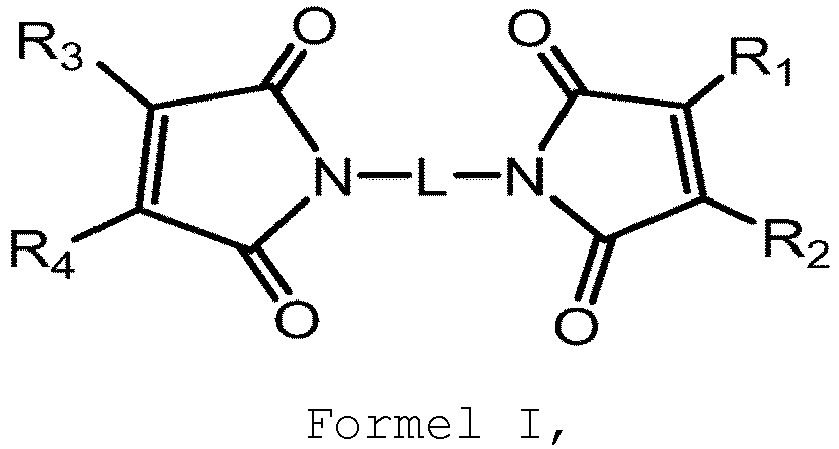 L ein Verknüpfungsanteil ist undR1-R4 jeweils unabhängig aus Wasserstoff, Alkyl und Cycloalkyl ausgewählt ist.
 - Verfahren (400) nach einem der Ansprüche 1 und 4-11, wobei die besagte Formulierung, die den besagten Polyimidvorläufer enthält, weiterhin ein organisches Lösungsmittel umfasst.
- Verfahren (400) nach Anspruch 12, wobei das besagte organische Lösungsmittel ein polares organisches Lösungsmittel ist.
- Verfahren (400) nach Anspruch 12 oder 13, wobei das besagte organische Lösungsmittel eine Siedetemperatur von weniger als 190 °C und/oder eine Verdunstungsrate von weniger als 1 oder weniger als 0,5 aufweist.
- Verfahren (400) nach einem der Ansprüche 12-14, wobei ein Gewichtsverhältnis des besagten Polyimids und des besagten organischen Lösungsmittels in der Formulierung von 50:50 bis 90:10 reicht.
Applications Claiming Priority (2)
| Application Number | Priority Date | Filing Date | Title |
|---|---|---|---|
| US201762610983P | 2017-12-28 | 2017-12-28 | |
| PCT/IL2018/051401 WO2019130310A1 (en) | 2017-12-28 | 2018-12-27 | Additive manufacturing employing polyimide-containing formulations |
Publications (2)
| Publication Number | Publication Date |
|---|---|
| EP3732023A1 EP3732023A1 (de) | 2020-11-04 |
| EP3732023B1 true EP3732023B1 (de) | 2024-06-26 |
Family
ID=65139056
Family Applications (1)
| Application Number | Title | Priority Date | Filing Date |
|---|---|---|---|
| EP18836915.1A Active EP3732023B1 (de) | 2017-12-28 | 2018-12-27 | Generative fertigung unter verwendung von polyimid enthaltenden formulierungen |
Country Status (3)
| Country | Link |
|---|---|
| US (2) | US12070897B2 (de) |
| EP (1) | EP3732023B1 (de) |
| WO (1) | WO2019130310A1 (de) |
Families Citing this family (16)
| Publication number | Priority date | Publication date | Assignee | Title |
|---|---|---|---|---|
| US10253195B2 (en) | 2014-11-24 | 2019-04-09 | Ppg Industries Ohio, Inc. | Coreactive materials and methods for three-dimensional printing |
| US12384097B2 (en) | 2017-08-18 | 2025-08-12 | Ppg Industries Ohio, Inc. | Additive manufacturing using reactive compositions |
| US10434704B2 (en) | 2017-08-18 | 2019-10-08 | Ppg Industries Ohio, Inc. | Additive manufacturing using polyurea materials |
| WO2019130312A2 (en) | 2017-12-28 | 2019-07-04 | Stratasys Ltd. | Additive manufacturing employing solvent-free polyimide-containing formulations |
| EP3732023B1 (de) * | 2017-12-28 | 2024-06-26 | Stratasys Ltd. | Generative fertigung unter verwendung von polyimid enthaltenden formulierungen |
| EP3856486B1 (de) | 2018-09-28 | 2025-05-28 | Stratasys Ltd. | Verfahren zur generativen fertigung mit partieller härtung |
| CN113710481A (zh) | 2019-02-11 | 2021-11-26 | Ppg工业俄亥俄公司 | 多层系统和制造多层系统的方法 |
| KR20210124439A (ko) | 2019-02-11 | 2021-10-14 | 피피지 인더스트리즈 오하이오 인코포레이티드 | 밀봉 캡의 3차원 인쇄 |
| EP3924187A1 (de) | 2019-02-11 | 2021-12-22 | PPG Industries Ohio, Inc. | Elastomere zusammensetzungen und verfahren zur verwendung |
| MX2021009606A (es) | 2019-02-11 | 2021-11-12 | Ppg Ind Ohio Inc | Métodos para fabricar componentes de sellado químicamente resistentes. |
| US11260601B2 (en) * | 2019-04-16 | 2022-03-01 | Brill, Inc. | System for printing binding agents |
| US11731198B2 (en) * | 2019-08-20 | 2023-08-22 | Rosemount Aerospace Inc. | Additive manufacturing system including an optical isolator |
| DE102019007982A1 (de) * | 2019-11-18 | 2021-05-20 | Voxeljet Ag | 3D-Druckvorrichtung mit vorteilhafter Strahlereinheit und Verfahren |
| KR102402737B1 (ko) * | 2021-03-25 | 2022-05-30 | 주식회사 나래나노텍 | 박막 건조장치 |
| EP4094942A1 (de) | 2021-05-26 | 2022-11-30 | TIGER Coatings GmbH & Co. KG | Strahlungshärtbare zusammensetzung zur generativen fertigung für elektronische anwendungen |
| CN120003023B (zh) * | 2025-03-27 | 2025-11-04 | 西安交通大学 | 一种高精度单细胞打印仪器及方法 |
Citations (2)
| Publication number | Priority date | Publication date | Assignee | Title |
|---|---|---|---|---|
| WO2016193934A1 (en) * | 2015-06-03 | 2016-12-08 | Sabic Global Technologies B.V. | 3d ink-jet printing of polyimide precursor |
| US20170203508A1 (en) * | 2014-03-25 | 2017-07-20 | Stratasys Ltd. | Method and system for fabricating cross-layer pattern |
Family Cites Families (29)
| Publication number | Priority date | Publication date | Assignee | Title |
|---|---|---|---|---|
| US4812511A (en) | 1986-07-15 | 1989-03-14 | Amoco Corporation | Ethylenically-unsaturated ethers of alkenyl phenols as reactive diluents for bismaleimides |
| CA2198745C (en) | 1994-09-02 | 2009-11-24 | Stephen M. Dershem | Thermosetting resin compositions containing maleimide and/or vinyl compounds |
| US6259962B1 (en) | 1999-03-01 | 2001-07-10 | Objet Geometries Ltd. | Apparatus and method for three dimensional model printing |
| US6658314B1 (en) | 1999-10-06 | 2003-12-02 | Objet Geometries Ltd. | System and method for three dimensional model printing |
| US6850334B1 (en) | 2000-01-18 | 2005-02-01 | Objet Geometries Ltd | System and method for three dimensional model printing |
| US7300619B2 (en) | 2000-03-13 | 2007-11-27 | Objet Geometries Ltd. | Compositions and methods for use in three dimensional model printing |
| US20030207959A1 (en) | 2000-03-13 | 2003-11-06 | Eduardo Napadensky | Compositions and methods for use in three dimensional model printing |
| US6569373B2 (en) * | 2000-03-13 | 2003-05-27 | Object Geometries Ltd. | Compositions and methods for use in three dimensional model printing |
| US20030151167A1 (en) | 2002-01-03 | 2003-08-14 | Kritchman Eliahu M. | Device, system and method for accurate printing of three dimensional objects |
| WO2004024447A2 (en) * | 2002-09-12 | 2004-03-25 | Objet Geometries Ltd. | Device, system and method for calibration in three-dimensional model printing |
| WO2004096527A2 (en) | 2003-05-01 | 2004-11-11 | Objet Geometries Ltd. | Rapid prototyping apparatus |
| TWI391424B (zh) | 2005-01-12 | 2013-04-01 | 太陽控股股份有限公司 | A hardened resin composition for inkjet and a hardened product thereof, and a printed circuit board using the same |
| WO2009013751A2 (en) | 2007-07-25 | 2009-01-29 | Objet Geometries Ltd. | Solid freeform fabrication using a plurality of modeling materials |
| US7962237B2 (en) | 2008-08-06 | 2011-06-14 | Objet Geometries Ltd. | Method and apparatus for optimizing a scanning plan in three-dimensional printing |
| CN106881856B (zh) | 2010-04-25 | 2020-01-24 | 斯特塔西有限公司 | 带外壳物体的实体无模制造 |
| JP5733071B2 (ja) | 2010-12-15 | 2015-06-10 | 宇部興産株式会社 | ポリイミド前駆体水溶液組成物の製造方法、及びポリイミド前駆体水溶液組成物 |
| US20150337147A1 (en) | 2014-05-22 | 2015-11-26 | Xerox Corporation | Reversible polymers in 3-d printing |
| US9808991B2 (en) | 2014-07-29 | 2017-11-07 | Cc3D Llc. | Method and apparatus for additive mechanical growth of tubular structures |
| US10399201B2 (en) | 2014-10-17 | 2019-09-03 | Applied Materials, Inc. | Advanced polishing pads having compositional gradients by use of an additive manufacturing process |
| EP3229853A1 (de) * | 2014-12-12 | 2017-10-18 | Ecole Polytechnique Fédérale de Lausanne (EPFL) | Verfahren zur herstellung einer struktur mit lebenden zellen |
| CN107614265A (zh) | 2015-03-25 | 2018-01-19 | 斯特拉塔西斯公司 | 导电油墨原位烧结的方法和系统 |
| EP3302938A1 (de) * | 2015-06-03 | 2018-04-11 | SABIC Global Technologies B.V. | Generative fertigung eines polyimidvorläufers durch materialextrusion |
| WO2017027482A1 (en) | 2015-08-08 | 2017-02-16 | Designer Molecules, Inc. | Anionic curable compositions |
| WO2018011674A1 (en) | 2016-07-11 | 2018-01-18 | Soreq Nuclear Research Center | Bismaleimide-based solution for inkjet ink for three dimensional printing |
| EP3375820A1 (de) * | 2017-03-13 | 2018-09-19 | TIGER Coatings GmbH & Co. KG | Verwendung einer wärmehärtbaren kunststoffpulverzusammensetzung |
| WO2019056019A1 (en) | 2017-09-18 | 2019-03-21 | The Regents Of The University Of Colorado, A Body Corporate | 3D PRINTING WITH PARTICLES OF NANOGEL POLYMER |
| US20190127599A1 (en) * | 2017-11-01 | 2019-05-02 | Industrial Technology Research Institute | Dispersion of ir absorption particles, inkjet ink, and method of 3d printing |
| EP3732023B1 (de) * | 2017-12-28 | 2024-06-26 | Stratasys Ltd. | Generative fertigung unter verwendung von polyimid enthaltenden formulierungen |
| WO2019130312A2 (en) | 2017-12-28 | 2019-07-04 | Stratasys Ltd. | Additive manufacturing employing solvent-free polyimide-containing formulations |
-
2018
- 2018-12-27 EP EP18836915.1A patent/EP3732023B1/de active Active
- 2018-12-27 US US16/958,713 patent/US12070897B2/en active Active
- 2018-12-27 WO PCT/IL2018/051401 patent/WO2019130310A1/en not_active Ceased
-
2024
- 2024-07-19 US US18/777,593 patent/US20240375346A1/en active Pending
Patent Citations (2)
| Publication number | Priority date | Publication date | Assignee | Title |
|---|---|---|---|---|
| US20170203508A1 (en) * | 2014-03-25 | 2017-07-20 | Stratasys Ltd. | Method and system for fabricating cross-layer pattern |
| WO2016193934A1 (en) * | 2015-06-03 | 2016-12-08 | Sabic Global Technologies B.V. | 3d ink-jet printing of polyimide precursor |
Also Published As
| Publication number | Publication date |
|---|---|
| US20210008793A1 (en) | 2021-01-14 |
| US20240375346A1 (en) | 2024-11-14 |
| WO2019130310A1 (en) | 2019-07-04 |
| US12070897B2 (en) | 2024-08-27 |
| EP3732023A1 (de) | 2020-11-04 |
Similar Documents
| Publication | Publication Date | Title |
|---|---|---|
| EP3732023B1 (de) | Generative fertigung unter verwendung von polyimid enthaltenden formulierungen | |
| US11958236B2 (en) | Method and system for solid freeform fabrication | |
| EP3515687B1 (de) | Verfahren zur herstellung von festen freiformen | |
| US12291603B2 (en) | Additive manufacturing employing solvent-free polyimide-containing formulations | |
| EP3105040B1 (de) | Zusammensetzung und verfahren zur additiven fertigung eines objekts | |
| EP3732045B1 (de) | Trägermaterialformulierungen für die generative fertigung von dreidimensionalen gegenständen bei niedrigen temperaturen | |
| CN113423788A (zh) | 使用经加强材料的积层制造 | |
| US20230257577A1 (en) | Additive manufacturing using materials that form a weak gel | |
| EP4363199B1 (de) | Wasserlösliche trägermaterialformulierung zur verwendung in der generativen fertigung | |
| HK40011628A (en) | Method and system for solid freeform fabrication |
Legal Events
| Date | Code | Title | Description |
|---|---|---|---|
| STAA | Information on the status of an ep patent application or granted ep patent |
Free format text: STATUS: UNKNOWN |
|
| STAA | Information on the status of an ep patent application or granted ep patent |
Free format text: STATUS: THE INTERNATIONAL PUBLICATION HAS BEEN MADE |
|
| PUAI | Public reference made under article 153(3) epc to a published international application that has entered the european phase |
Free format text: ORIGINAL CODE: 0009012 |
|
| STAA | Information on the status of an ep patent application or granted ep patent |
Free format text: STATUS: REQUEST FOR EXAMINATION WAS MADE |
|
| 17P | Request for examination filed |
Effective date: 20200728 |
|
| AK | Designated contracting states |
Kind code of ref document: A1 Designated state(s): AL AT BE BG CH CY CZ DE DK EE ES FI FR GB GR HR HU IE IS IT LI LT LU LV MC MK MT NL NO PL PT RO RS SE SI SK SM TR |
|
| AX | Request for extension of the european patent |
Extension state: BA ME |
|
| DAV | Request for validation of the european patent (deleted) | ||
| DAX | Request for extension of the european patent (deleted) | ||
| STAA | Information on the status of an ep patent application or granted ep patent |
Free format text: STATUS: EXAMINATION IS IN PROGRESS |
|
| 17Q | First examination report despatched |
Effective date: 20210914 |
|
| P01 | Opt-out of the competence of the unified patent court (upc) registered |
Effective date: 20230719 |
|
| GRAP | Despatch of communication of intention to grant a patent |
Free format text: ORIGINAL CODE: EPIDOSNIGR1 |
|
| STAA | Information on the status of an ep patent application or granted ep patent |
Free format text: STATUS: GRANT OF PATENT IS INTENDED |
|
| INTG | Intention to grant announced |
Effective date: 20240311 |
|
| GRAS | Grant fee paid |
Free format text: ORIGINAL CODE: EPIDOSNIGR3 |
|
| GRAA | (expected) grant |
Free format text: ORIGINAL CODE: 0009210 |
|
| STAA | Information on the status of an ep patent application or granted ep patent |
Free format text: STATUS: THE PATENT HAS BEEN GRANTED |
|
| AK | Designated contracting states |
Kind code of ref document: B1 Designated state(s): AL AT BE BG CH CY CZ DE DK EE ES FI FR GB GR HR HU IE IS IT LI LT LU LV MC MK MT NL NO PL PT RO RS SE SI SK SM TR |
|
| REG | Reference to a national code |
Ref country code: GB Ref legal event code: FG4D |
|
| REG | Reference to a national code |
Ref country code: CH Ref legal event code: EP |
|
| REG | Reference to a national code |
Ref country code: DE Ref legal event code: R096 Ref document number: 602018071087 Country of ref document: DE |
|
| PG25 | Lapsed in a contracting state [announced via postgrant information from national office to epo] |
Ref country code: BG Free format text: LAPSE BECAUSE OF FAILURE TO SUBMIT A TRANSLATION OF THE DESCRIPTION OR TO PAY THE FEE WITHIN THE PRESCRIBED TIME-LIMIT Effective date: 20240626 |
|
| PG25 | Lapsed in a contracting state [announced via postgrant information from national office to epo] |
Ref country code: FI Free format text: LAPSE BECAUSE OF FAILURE TO SUBMIT A TRANSLATION OF THE DESCRIPTION OR TO PAY THE FEE WITHIN THE PRESCRIBED TIME-LIMIT Effective date: 20240626 Ref country code: HR Free format text: LAPSE BECAUSE OF FAILURE TO SUBMIT A TRANSLATION OF THE DESCRIPTION OR TO PAY THE FEE WITHIN THE PRESCRIBED TIME-LIMIT Effective date: 20240626 |
|
| REG | Reference to a national code |
Ref country code: LT Ref legal event code: MG9D |
|
| PG25 | Lapsed in a contracting state [announced via postgrant information from national office to epo] |
Ref country code: GR Free format text: LAPSE BECAUSE OF FAILURE TO SUBMIT A TRANSLATION OF THE DESCRIPTION OR TO PAY THE FEE WITHIN THE PRESCRIBED TIME-LIMIT Effective date: 20240927 |
|
| PG25 | Lapsed in a contracting state [announced via postgrant information from national office to epo] |
Ref country code: LV Free format text: LAPSE BECAUSE OF FAILURE TO SUBMIT A TRANSLATION OF THE DESCRIPTION OR TO PAY THE FEE WITHIN THE PRESCRIBED TIME-LIMIT Effective date: 20240626 |
|
| REG | Reference to a national code |
Ref country code: NL Ref legal event code: MP Effective date: 20240626 |
|
| PG25 | Lapsed in a contracting state [announced via postgrant information from national office to epo] |
Ref country code: NO Free format text: LAPSE BECAUSE OF FAILURE TO SUBMIT A TRANSLATION OF THE DESCRIPTION OR TO PAY THE FEE WITHIN THE PRESCRIBED TIME-LIMIT Effective date: 20240926 Ref country code: LV Free format text: LAPSE BECAUSE OF FAILURE TO SUBMIT A TRANSLATION OF THE DESCRIPTION OR TO PAY THE FEE WITHIN THE PRESCRIBED TIME-LIMIT Effective date: 20240626 Ref country code: HR Free format text: LAPSE BECAUSE OF FAILURE TO SUBMIT A TRANSLATION OF THE DESCRIPTION OR TO PAY THE FEE WITHIN THE PRESCRIBED TIME-LIMIT Effective date: 20240626 Ref country code: GR Free format text: LAPSE BECAUSE OF FAILURE TO SUBMIT A TRANSLATION OF THE DESCRIPTION OR TO PAY THE FEE WITHIN THE PRESCRIBED TIME-LIMIT Effective date: 20240927 Ref country code: FI Free format text: LAPSE BECAUSE OF FAILURE TO SUBMIT A TRANSLATION OF THE DESCRIPTION OR TO PAY THE FEE WITHIN THE PRESCRIBED TIME-LIMIT Effective date: 20240626 Ref country code: BG Free format text: LAPSE BECAUSE OF FAILURE TO SUBMIT A TRANSLATION OF THE DESCRIPTION OR TO PAY THE FEE WITHIN THE PRESCRIBED TIME-LIMIT Effective date: 20240626 Ref country code: RS Free format text: LAPSE BECAUSE OF FAILURE TO SUBMIT A TRANSLATION OF THE DESCRIPTION OR TO PAY THE FEE WITHIN THE PRESCRIBED TIME-LIMIT Effective date: 20240926 |
|
| PG25 | Lapsed in a contracting state [announced via postgrant information from national office to epo] |
Ref country code: NL Free format text: LAPSE BECAUSE OF FAILURE TO SUBMIT A TRANSLATION OF THE DESCRIPTION OR TO PAY THE FEE WITHIN THE PRESCRIBED TIME-LIMIT Effective date: 20240626 |
|
| REG | Reference to a national code |
Ref country code: AT Ref legal event code: MK05 Ref document number: 1697360 Country of ref document: AT Kind code of ref document: T Effective date: 20240626 |
|
| PG25 | Lapsed in a contracting state [announced via postgrant information from national office to epo] |
Ref country code: NL Free format text: LAPSE BECAUSE OF FAILURE TO SUBMIT A TRANSLATION OF THE DESCRIPTION OR TO PAY THE FEE WITHIN THE PRESCRIBED TIME-LIMIT Effective date: 20240626 |
|
| PG25 | Lapsed in a contracting state [announced via postgrant information from national office to epo] |
Ref country code: PT Free format text: LAPSE BECAUSE OF FAILURE TO SUBMIT A TRANSLATION OF THE DESCRIPTION OR TO PAY THE FEE WITHIN THE PRESCRIBED TIME-LIMIT Effective date: 20241028 |
|
| PG25 | Lapsed in a contracting state [announced via postgrant information from national office to epo] |
Ref country code: PT Free format text: LAPSE BECAUSE OF FAILURE TO SUBMIT A TRANSLATION OF THE DESCRIPTION OR TO PAY THE FEE WITHIN THE PRESCRIBED TIME-LIMIT Effective date: 20241028 |
|
| PG25 | Lapsed in a contracting state [announced via postgrant information from national office to epo] |
Ref country code: PL Free format text: LAPSE BECAUSE OF FAILURE TO SUBMIT A TRANSLATION OF THE DESCRIPTION OR TO PAY THE FEE WITHIN THE PRESCRIBED TIME-LIMIT Effective date: 20240626 |
|
| PG25 | Lapsed in a contracting state [announced via postgrant information from national office to epo] |
Ref country code: EE Free format text: LAPSE BECAUSE OF FAILURE TO SUBMIT A TRANSLATION OF THE DESCRIPTION OR TO PAY THE FEE WITHIN THE PRESCRIBED TIME-LIMIT Effective date: 20240626 |
|
| PG25 | Lapsed in a contracting state [announced via postgrant information from national office to epo] |
Ref country code: IS Free format text: LAPSE BECAUSE OF FAILURE TO SUBMIT A TRANSLATION OF THE DESCRIPTION OR TO PAY THE FEE WITHIN THE PRESCRIBED TIME-LIMIT Effective date: 20241026 Ref country code: AT Free format text: LAPSE BECAUSE OF FAILURE TO SUBMIT A TRANSLATION OF THE DESCRIPTION OR TO PAY THE FEE WITHIN THE PRESCRIBED TIME-LIMIT Effective date: 20240626 |
|
| PG25 | Lapsed in a contracting state [announced via postgrant information from national office to epo] |
Ref country code: CZ Free format text: LAPSE BECAUSE OF FAILURE TO SUBMIT A TRANSLATION OF THE DESCRIPTION OR TO PAY THE FEE WITHIN THE PRESCRIBED TIME-LIMIT Effective date: 20240626 |
|
| PG25 | Lapsed in a contracting state [announced via postgrant information from national office to epo] |
Ref country code: SK Free format text: LAPSE BECAUSE OF FAILURE TO SUBMIT A TRANSLATION OF THE DESCRIPTION OR TO PAY THE FEE WITHIN THE PRESCRIBED TIME-LIMIT Effective date: 20240626 Ref country code: RO Free format text: LAPSE BECAUSE OF FAILURE TO SUBMIT A TRANSLATION OF THE DESCRIPTION OR TO PAY THE FEE WITHIN THE PRESCRIBED TIME-LIMIT Effective date: 20240626 |
|
| PG25 | Lapsed in a contracting state [announced via postgrant information from national office to epo] |
Ref country code: ES Free format text: LAPSE BECAUSE OF FAILURE TO SUBMIT A TRANSLATION OF THE DESCRIPTION OR TO PAY THE FEE WITHIN THE PRESCRIBED TIME-LIMIT Effective date: 20240626 Ref country code: SM Free format text: LAPSE BECAUSE OF FAILURE TO SUBMIT A TRANSLATION OF THE DESCRIPTION OR TO PAY THE FEE WITHIN THE PRESCRIBED TIME-LIMIT Effective date: 20240626 |
|
| PG25 | Lapsed in a contracting state [announced via postgrant information from national office to epo] |
Ref country code: SM Free format text: LAPSE BECAUSE OF FAILURE TO SUBMIT A TRANSLATION OF THE DESCRIPTION OR TO PAY THE FEE WITHIN THE PRESCRIBED TIME-LIMIT Effective date: 20240626 Ref country code: SK Free format text: LAPSE BECAUSE OF FAILURE TO SUBMIT A TRANSLATION OF THE DESCRIPTION OR TO PAY THE FEE WITHIN THE PRESCRIBED TIME-LIMIT Effective date: 20240626 Ref country code: RO Free format text: LAPSE BECAUSE OF FAILURE TO SUBMIT A TRANSLATION OF THE DESCRIPTION OR TO PAY THE FEE WITHIN THE PRESCRIBED TIME-LIMIT Effective date: 20240626 Ref country code: PL Free format text: LAPSE BECAUSE OF FAILURE TO SUBMIT A TRANSLATION OF THE DESCRIPTION OR TO PAY THE FEE WITHIN THE PRESCRIBED TIME-LIMIT Effective date: 20240626 Ref country code: IS Free format text: LAPSE BECAUSE OF FAILURE TO SUBMIT A TRANSLATION OF THE DESCRIPTION OR TO PAY THE FEE WITHIN THE PRESCRIBED TIME-LIMIT Effective date: 20241026 Ref country code: ES Free format text: LAPSE BECAUSE OF FAILURE TO SUBMIT A TRANSLATION OF THE DESCRIPTION OR TO PAY THE FEE WITHIN THE PRESCRIBED TIME-LIMIT Effective date: 20240626 Ref country code: EE Free format text: LAPSE BECAUSE OF FAILURE TO SUBMIT A TRANSLATION OF THE DESCRIPTION OR TO PAY THE FEE WITHIN THE PRESCRIBED TIME-LIMIT Effective date: 20240626 Ref country code: CZ Free format text: LAPSE BECAUSE OF FAILURE TO SUBMIT A TRANSLATION OF THE DESCRIPTION OR TO PAY THE FEE WITHIN THE PRESCRIBED TIME-LIMIT Effective date: 20240626 Ref country code: AT Free format text: LAPSE BECAUSE OF FAILURE TO SUBMIT A TRANSLATION OF THE DESCRIPTION OR TO PAY THE FEE WITHIN THE PRESCRIBED TIME-LIMIT Effective date: 20240626 |
|
| PG25 | Lapsed in a contracting state [announced via postgrant information from national office to epo] |
Ref country code: IT Free format text: LAPSE BECAUSE OF FAILURE TO SUBMIT A TRANSLATION OF THE DESCRIPTION OR TO PAY THE FEE WITHIN THE PRESCRIBED TIME-LIMIT Effective date: 20240626 |
|
| REG | Reference to a national code |
Ref country code: DE Ref legal event code: R097 Ref document number: 602018071087 Country of ref document: DE |
|
| PG25 | Lapsed in a contracting state [announced via postgrant information from national office to epo] |
Ref country code: DK Free format text: LAPSE BECAUSE OF FAILURE TO SUBMIT A TRANSLATION OF THE DESCRIPTION OR TO PAY THE FEE WITHIN THE PRESCRIBED TIME-LIMIT Effective date: 20240626 |
|
| PLBE | No opposition filed within time limit |
Free format text: ORIGINAL CODE: 0009261 |
|
| STAA | Information on the status of an ep patent application or granted ep patent |
Free format text: STATUS: NO OPPOSITION FILED WITHIN TIME LIMIT |
|
| 26N | No opposition filed |
Effective date: 20250327 |
|
| PG25 | Lapsed in a contracting state [announced via postgrant information from national office to epo] |
Ref country code: MC Free format text: LAPSE BECAUSE OF FAILURE TO SUBMIT A TRANSLATION OF THE DESCRIPTION OR TO PAY THE FEE WITHIN THE PRESCRIBED TIME-LIMIT Effective date: 20240626 |
|
| REG | Reference to a national code |
Ref country code: CH Ref legal event code: PL |
|
| PG25 | Lapsed in a contracting state [announced via postgrant information from national office to epo] |
Ref country code: LU Free format text: LAPSE BECAUSE OF NON-PAYMENT OF DUE FEES Effective date: 20241227 |
|
| PG25 | Lapsed in a contracting state [announced via postgrant information from national office to epo] |
Ref country code: SE Free format text: LAPSE BECAUSE OF FAILURE TO SUBMIT A TRANSLATION OF THE DESCRIPTION OR TO PAY THE FEE WITHIN THE PRESCRIBED TIME-LIMIT Effective date: 20240626 |
|
| REG | Reference to a national code |
Ref country code: BE Ref legal event code: MM Effective date: 20241231 |
|
| PG25 | Lapsed in a contracting state [announced via postgrant information from national office to epo] |
Ref country code: BE Free format text: LAPSE BECAUSE OF NON-PAYMENT OF DUE FEES Effective date: 20241231 |
|
| PG25 | Lapsed in a contracting state [announced via postgrant information from national office to epo] |
Ref country code: CH Free format text: LAPSE BECAUSE OF NON-PAYMENT OF DUE FEES Effective date: 20241231 |
|
| PG25 | Lapsed in a contracting state [announced via postgrant information from national office to epo] |
Ref country code: IE Free format text: LAPSE BECAUSE OF NON-PAYMENT OF DUE FEES Effective date: 20241227 |
|
| PGFP | Annual fee paid to national office [announced via postgrant information from national office to epo] |
Ref country code: DE Payment date: 20251126 Year of fee payment: 8 |
|
| PGFP | Annual fee paid to national office [announced via postgrant information from national office to epo] |
Ref country code: GB Payment date: 20251120 Year of fee payment: 8 |
|
| PGFP | Annual fee paid to national office [announced via postgrant information from national office to epo] |
Ref country code: FR Payment date: 20251120 Year of fee payment: 8 |