EP3732028B1 - Versiegelungsverfahren unter verwendung eines dünnen flexiblen deckels zum hermetischen verschliessen einer breiten öffnung, begrenzt durch einen innenflansch - Google Patents
Versiegelungsverfahren unter verwendung eines dünnen flexiblen deckels zum hermetischen verschliessen einer breiten öffnung, begrenzt durch einen innenflansch Download PDFInfo
- Publication number
- EP3732028B1 EP3732028B1 EP17840490.1A EP17840490A EP3732028B1 EP 3732028 B1 EP3732028 B1 EP 3732028B1 EP 17840490 A EP17840490 A EP 17840490A EP 3732028 B1 EP3732028 B1 EP 3732028B1
- Authority
- EP
- European Patent Office
- Prior art keywords
- flange
- side wall
- annular
- lid
- container
- Prior art date
- Legal status (The legal status is an assumption and is not a legal conclusion. Google has not performed a legal analysis and makes no representation as to the accuracy of the status listed.)
- Active
Links
Images


Classifications
-
- B—PERFORMING OPERATIONS; TRANSPORTING
- B29—WORKING OF PLASTICS; WORKING OF SUBSTANCES IN A PLASTIC STATE IN GENERAL
- B29C—SHAPING OR JOINING OF PLASTICS; SHAPING OF MATERIAL IN A PLASTIC STATE, NOT OTHERWISE PROVIDED FOR; AFTER-TREATMENT OF THE SHAPED PRODUCTS, e.g. REPAIRING
- B29C66/00—General aspects of processes or apparatus for joining preformed parts
- B29C66/50—General aspects of joining tubular articles; General aspects of joining long products, i.e. bars or profiled elements; General aspects of joining single elements to tubular articles, hollow articles or bars; General aspects of joining several hollow-preforms to form hollow or tubular articles
- B29C66/51—Joining tubular articles, profiled elements or bars; Joining single elements to tubular articles, hollow articles or bars; Joining several hollow-preforms to form hollow or tubular articles
- B29C66/53—Joining single elements to tubular articles, hollow articles or bars
- B29C66/534—Joining single elements to open ends of tubular or hollow articles or to the ends of bars
- B29C66/5346—Joining single elements to open ends of tubular or hollow articles or to the ends of bars said single elements being substantially flat
- B29C66/53461—Joining single elements to open ends of tubular or hollow articles or to the ends of bars said single elements being substantially flat joining substantially flat covers and/or substantially flat bottoms to open ends of container bodies
-
- B—PERFORMING OPERATIONS; TRANSPORTING
- B29—WORKING OF PLASTICS; WORKING OF SUBSTANCES IN A PLASTIC STATE IN GENERAL
- B29C—SHAPING OR JOINING OF PLASTICS; SHAPING OF MATERIAL IN A PLASTIC STATE, NOT OTHERWISE PROVIDED FOR; AFTER-TREATMENT OF THE SHAPED PRODUCTS, e.g. REPAIRING
- B29C65/00—Joining or sealing of preformed parts, e.g. welding of plastics materials; Apparatus therefor
- B29C65/02—Joining or sealing of preformed parts, e.g. welding of plastics materials; Apparatus therefor by heating, with or without pressure
- B29C65/18—Joining or sealing of preformed parts, e.g. welding of plastics materials; Apparatus therefor by heating, with or without pressure using heated tools
-
- B—PERFORMING OPERATIONS; TRANSPORTING
- B29—WORKING OF PLASTICS; WORKING OF SUBSTANCES IN A PLASTIC STATE IN GENERAL
- B29C—SHAPING OR JOINING OF PLASTICS; SHAPING OF MATERIAL IN A PLASTIC STATE, NOT OTHERWISE PROVIDED FOR; AFTER-TREATMENT OF THE SHAPED PRODUCTS, e.g. REPAIRING
- B29C65/00—Joining or sealing of preformed parts, e.g. welding of plastics materials; Apparatus therefor
- B29C65/76—Making non-permanent or releasable joints
-
- B—PERFORMING OPERATIONS; TRANSPORTING
- B29—WORKING OF PLASTICS; WORKING OF SUBSTANCES IN A PLASTIC STATE IN GENERAL
- B29C—SHAPING OR JOINING OF PLASTICS; SHAPING OF MATERIAL IN A PLASTIC STATE, NOT OTHERWISE PROVIDED FOR; AFTER-TREATMENT OF THE SHAPED PRODUCTS, e.g. REPAIRING
- B29C65/00—Joining or sealing of preformed parts, e.g. welding of plastics materials; Apparatus therefor
- B29C65/78—Means for handling the parts to be joined, e.g. for making containers or hollow articles, e.g. means for handling sheets, plates, web-like materials, tubular articles, hollow articles or elements to be joined therewith; Means for discharging the joined articles from the joining apparatus
- B29C65/7841—Holding or clamping means for handling purposes
- B29C65/7847—Holding or clamping means for handling purposes using vacuum to hold at least one of the parts to be joined
-
- B—PERFORMING OPERATIONS; TRANSPORTING
- B29—WORKING OF PLASTICS; WORKING OF SUBSTANCES IN A PLASTIC STATE IN GENERAL
- B29C—SHAPING OR JOINING OF PLASTICS; SHAPING OF MATERIAL IN A PLASTIC STATE, NOT OTHERWISE PROVIDED FOR; AFTER-TREATMENT OF THE SHAPED PRODUCTS, e.g. REPAIRING
- B29C66/00—General aspects of processes or apparatus for joining preformed parts
- B29C66/01—General aspects dealing with the joint area or with the area to be joined
- B29C66/05—Particular design of joint configurations
- B29C66/20—Particular design of joint configurations particular design of the joint lines, e.g. of the weld lines
- B29C66/24—Particular design of joint configurations particular design of the joint lines, e.g. of the weld lines said joint lines being closed or non-straight
- B29C66/242—Particular design of joint configurations particular design of the joint lines, e.g. of the weld lines said joint lines being closed or non-straight said joint lines being closed, i.e. forming closed contours
- B29C66/2422—Particular design of joint configurations particular design of the joint lines, e.g. of the weld lines said joint lines being closed or non-straight said joint lines being closed, i.e. forming closed contours being circular, oval or elliptical
- B29C66/24221—Particular design of joint configurations particular design of the joint lines, e.g. of the weld lines said joint lines being closed or non-straight said joint lines being closed, i.e. forming closed contours being circular, oval or elliptical being circular
-
- B—PERFORMING OPERATIONS; TRANSPORTING
- B29—WORKING OF PLASTICS; WORKING OF SUBSTANCES IN A PLASTIC STATE IN GENERAL
- B29C—SHAPING OR JOINING OF PLASTICS; SHAPING OF MATERIAL IN A PLASTIC STATE, NOT OTHERWISE PROVIDED FOR; AFTER-TREATMENT OF THE SHAPED PRODUCTS, e.g. REPAIRING
- B29C66/00—General aspects of processes or apparatus for joining preformed parts
- B29C66/70—General aspects of processes or apparatus for joining preformed parts characterised by the composition, physical properties or the structure of the material of the parts to be joined; Joining with non-plastics material
- B29C66/71—General aspects of processes or apparatus for joining preformed parts characterised by the composition, physical properties or the structure of the material of the parts to be joined; Joining with non-plastics material characterised by the composition of the plastics material of the parts to be joined
-
- B—PERFORMING OPERATIONS; TRANSPORTING
- B29—WORKING OF PLASTICS; WORKING OF SUBSTANCES IN A PLASTIC STATE IN GENERAL
- B29C—SHAPING OR JOINING OF PLASTICS; SHAPING OF MATERIAL IN A PLASTIC STATE, NOT OTHERWISE PROVIDED FOR; AFTER-TREATMENT OF THE SHAPED PRODUCTS, e.g. REPAIRING
- B29C66/00—General aspects of processes or apparatus for joining preformed parts
- B29C66/70—General aspects of processes or apparatus for joining preformed parts characterised by the composition, physical properties or the structure of the material of the parts to be joined; Joining with non-plastics material
- B29C66/73—General aspects of processes or apparatus for joining preformed parts characterised by the composition, physical properties or the structure of the material of the parts to be joined; Joining with non-plastics material characterised by the intensive physical properties of the material of the parts to be joined, by the optical properties of the material of the parts to be joined, by the extensive physical properties of the parts to be joined, by the state of the material of the parts to be joined or by the material of the parts to be joined being a thermoplastic or a thermoset
- B29C66/739—General aspects of processes or apparatus for joining preformed parts characterised by the composition, physical properties or the structure of the material of the parts to be joined; Joining with non-plastics material characterised by the intensive physical properties of the material of the parts to be joined, by the optical properties of the material of the parts to be joined, by the extensive physical properties of the parts to be joined, by the state of the material of the parts to be joined or by the material of the parts to be joined being a thermoplastic or a thermoset characterised by the material of the parts to be joined being a thermoplastic or a thermoset
- B29C66/7392—General aspects of processes or apparatus for joining preformed parts characterised by the composition, physical properties or the structure of the material of the parts to be joined; Joining with non-plastics material characterised by the intensive physical properties of the material of the parts to be joined, by the optical properties of the material of the parts to be joined, by the extensive physical properties of the parts to be joined, by the state of the material of the parts to be joined or by the material of the parts to be joined being a thermoplastic or a thermoset characterised by the material of the parts to be joined being a thermoplastic or a thermoset characterised by the material of at least one of the parts being a thermoplastic
-
- B—PERFORMING OPERATIONS; TRANSPORTING
- B29—WORKING OF PLASTICS; WORKING OF SUBSTANCES IN A PLASTIC STATE IN GENERAL
- B29C—SHAPING OR JOINING OF PLASTICS; SHAPING OF MATERIAL IN A PLASTIC STATE, NOT OTHERWISE PROVIDED FOR; AFTER-TREATMENT OF THE SHAPED PRODUCTS, e.g. REPAIRING
- B29C66/00—General aspects of processes or apparatus for joining preformed parts
- B29C66/90—Measuring or controlling the joining process
- B29C66/92—Measuring or controlling the joining process by measuring or controlling the pressure, the force, the mechanical power or the displacement of the joining tools
- B29C66/924—Measuring or controlling the joining process by measuring or controlling the pressure, the force, the mechanical power or the displacement of the joining tools by controlling or regulating the pressure, the force, the mechanical power or the displacement of the joining tools
- B29C66/9241—Measuring or controlling the joining process by measuring or controlling the pressure, the force, the mechanical power or the displacement of the joining tools by controlling or regulating the pressure, the force, the mechanical power or the displacement of the joining tools by controlling or regulating the pressure, the force or the mechanical power
- B29C66/92441—Measuring or controlling the joining process by measuring or controlling the pressure, the force, the mechanical power or the displacement of the joining tools by controlling or regulating the pressure, the force, the mechanical power or the displacement of the joining tools by controlling or regulating the pressure, the force or the mechanical power the pressure, the force or the mechanical power being non-constant over time
- B29C66/92443—Measuring or controlling the joining process by measuring or controlling the pressure, the force, the mechanical power or the displacement of the joining tools by controlling or regulating the pressure, the force, the mechanical power or the displacement of the joining tools by controlling or regulating the pressure, the force or the mechanical power the pressure, the force or the mechanical power being non-constant over time following a pressure-time profile
- B29C66/92445—Measuring or controlling the joining process by measuring or controlling the pressure, the force, the mechanical power or the displacement of the joining tools by controlling or regulating the pressure, the force, the mechanical power or the displacement of the joining tools by controlling or regulating the pressure, the force or the mechanical power the pressure, the force or the mechanical power being non-constant over time following a pressure-time profile by steps
-
- B—PERFORMING OPERATIONS; TRANSPORTING
- B65—CONVEYING; PACKING; STORING; HANDLING THIN OR FILAMENTARY MATERIAL
- B65B—MACHINES, APPARATUS OR DEVICES FOR, OR METHODS OF, PACKAGING ARTICLES OR MATERIALS; UNPACKING
- B65B7/00—Closing containers or receptacles after filling
- B65B7/16—Closing semi-rigid or rigid containers or receptacles not deformed by, or not taking-up shape of, contents, e.g. boxes or cartons
- B65B7/162—Closing semi-rigid or rigid containers or receptacles not deformed by, or not taking-up shape of, contents, e.g. boxes or cartons by feeding web material to securing means
- B65B7/164—Securing by heat-sealing
-
- B—PERFORMING OPERATIONS; TRANSPORTING
- B65—CONVEYING; PACKING; STORING; HANDLING THIN OR FILAMENTARY MATERIAL
- B65D—CONTAINERS FOR STORAGE OR TRANSPORT OF ARTICLES OR MATERIALS, e.g. BAGS, BARRELS, BOTTLES, BOXES, CANS, CARTONS, CRATES, DRUMS, JARS, TANKS, HOPPERS, FORWARDING CONTAINERS; ACCESSORIES, CLOSURES, OR FITTINGS THEREFOR; PACKAGING ELEMENTS; PACKAGES
- B65D1/00—Rigid or semi-rigid containers having bodies formed in one piece, e.g. by casting metallic material, by moulding plastics, by blowing vitreous material, by throwing ceramic material, by moulding pulped fibrous material or by deep-drawing operations performed on sheet material
- B65D1/12—Cans, casks, barrels, or drums
- B65D1/14—Cans, casks, barrels, or drums characterised by shape
- B65D1/16—Cans, casks, barrels, or drums characterised by shape of curved cross-section, e.g. cylindrical
-
- B—PERFORMING OPERATIONS; TRANSPORTING
- B29—WORKING OF PLASTICS; WORKING OF SUBSTANCES IN A PLASTIC STATE IN GENERAL
- B29C—SHAPING OR JOINING OF PLASTICS; SHAPING OF MATERIAL IN A PLASTIC STATE, NOT OTHERWISE PROVIDED FOR; AFTER-TREATMENT OF THE SHAPED PRODUCTS, e.g. REPAIRING
- B29C2793/00—Shaping techniques involving a cutting or machining operation
- B29C2793/0081—Shaping techniques involving a cutting or machining operation before shaping
-
- B—PERFORMING OPERATIONS; TRANSPORTING
- B29—WORKING OF PLASTICS; WORKING OF SUBSTANCES IN A PLASTIC STATE IN GENERAL
- B29C—SHAPING OR JOINING OF PLASTICS; SHAPING OF MATERIAL IN A PLASTIC STATE, NOT OTHERWISE PROVIDED FOR; AFTER-TREATMENT OF THE SHAPED PRODUCTS, e.g. REPAIRING
- B29C66/00—General aspects of processes or apparatus for joining preformed parts
- B29C66/01—General aspects dealing with the joint area or with the area to be joined
- B29C66/02—Preparation of the material, in the area to be joined, prior to joining or welding
- B29C66/022—Mechanical pre-treatments, e.g. reshaping
- B29C66/0224—Mechanical pre-treatments, e.g. reshaping with removal of material
- B29C66/02241—Cutting, e.g. by using waterjets, or sawing
-
- B—PERFORMING OPERATIONS; TRANSPORTING
- B29—WORKING OF PLASTICS; WORKING OF SUBSTANCES IN A PLASTIC STATE IN GENERAL
- B29C—SHAPING OR JOINING OF PLASTICS; SHAPING OF MATERIAL IN A PLASTIC STATE, NOT OTHERWISE PROVIDED FOR; AFTER-TREATMENT OF THE SHAPED PRODUCTS, e.g. REPAIRING
- B29C66/00—General aspects of processes or apparatus for joining preformed parts
- B29C66/01—General aspects dealing with the joint area or with the area to be joined
- B29C66/05—Particular design of joint configurations
- B29C66/10—Particular design of joint configurations particular design of the joint cross-sections
- B29C66/11—Joint cross-sections comprising a single joint-segment, i.e. one of the parts to be joined comprising a single joint-segment in the joint cross-section
- B29C66/112—Single lapped joints
-
- B—PERFORMING OPERATIONS; TRANSPORTING
- B29—WORKING OF PLASTICS; WORKING OF SUBSTANCES IN A PLASTIC STATE IN GENERAL
- B29C—SHAPING OR JOINING OF PLASTICS; SHAPING OF MATERIAL IN A PLASTIC STATE, NOT OTHERWISE PROVIDED FOR; AFTER-TREATMENT OF THE SHAPED PRODUCTS, e.g. REPAIRING
- B29C66/00—General aspects of processes or apparatus for joining preformed parts
- B29C66/01—General aspects dealing with the joint area or with the area to be joined
- B29C66/05—Particular design of joint configurations
- B29C66/10—Particular design of joint configurations particular design of the joint cross-sections
- B29C66/12—Joint cross-sections combining only two joint-segments; Tongue and groove joints; Tenon and mortise joints; Stepped joint cross-sections
- B29C66/122—Joint cross-sections combining only two joint-segments, i.e. one of the parts to be joined comprising only two joint-segments in the joint cross-section
- B29C66/1222—Joint cross-sections combining only two joint-segments, i.e. one of the parts to be joined comprising only two joint-segments in the joint cross-section comprising at least a lapped joint-segment
-
- B—PERFORMING OPERATIONS; TRANSPORTING
- B29—WORKING OF PLASTICS; WORKING OF SUBSTANCES IN A PLASTIC STATE IN GENERAL
- B29C—SHAPING OR JOINING OF PLASTICS; SHAPING OF MATERIAL IN A PLASTIC STATE, NOT OTHERWISE PROVIDED FOR; AFTER-TREATMENT OF THE SHAPED PRODUCTS, e.g. REPAIRING
- B29C66/00—General aspects of processes or apparatus for joining preformed parts
- B29C66/01—General aspects dealing with the joint area or with the area to be joined
- B29C66/05—Particular design of joint configurations
- B29C66/10—Particular design of joint configurations particular design of the joint cross-sections
- B29C66/12—Joint cross-sections combining only two joint-segments; Tongue and groove joints; Tenon and mortise joints; Stepped joint cross-sections
- B29C66/122—Joint cross-sections combining only two joint-segments, i.e. one of the parts to be joined comprising only two joint-segments in the joint cross-section
- B29C66/1226—Joint cross-sections combining only two joint-segments, i.e. one of the parts to be joined comprising only two joint-segments in the joint cross-section comprising at least one bevelled joint-segment
-
- B—PERFORMING OPERATIONS; TRANSPORTING
- B29—WORKING OF PLASTICS; WORKING OF SUBSTANCES IN A PLASTIC STATE IN GENERAL
- B29C—SHAPING OR JOINING OF PLASTICS; SHAPING OF MATERIAL IN A PLASTIC STATE, NOT OTHERWISE PROVIDED FOR; AFTER-TREATMENT OF THE SHAPED PRODUCTS, e.g. REPAIRING
- B29C66/00—General aspects of processes or apparatus for joining preformed parts
- B29C66/01—General aspects dealing with the joint area or with the area to be joined
- B29C66/05—Particular design of joint configurations
- B29C66/10—Particular design of joint configurations particular design of the joint cross-sections
- B29C66/13—Single flanged joints; Fin-type joints; Single hem joints; Edge joints; Interpenetrating fingered joints; Other specific particular designs of joint cross-sections not provided for in groups B29C66/11 - B29C66/12
- B29C66/131—Single flanged joints, i.e. one of the parts to be joined being rigid and flanged in the joint area
-
- B—PERFORMING OPERATIONS; TRANSPORTING
- B29—WORKING OF PLASTICS; WORKING OF SUBSTANCES IN A PLASTIC STATE IN GENERAL
- B29C—SHAPING OR JOINING OF PLASTICS; SHAPING OF MATERIAL IN A PLASTIC STATE, NOT OTHERWISE PROVIDED FOR; AFTER-TREATMENT OF THE SHAPED PRODUCTS, e.g. REPAIRING
- B29C66/00—General aspects of processes or apparatus for joining preformed parts
- B29C66/70—General aspects of processes or apparatus for joining preformed parts characterised by the composition, physical properties or the structure of the material of the parts to be joined; Joining with non-plastics material
- B29C66/73—General aspects of processes or apparatus for joining preformed parts characterised by the composition, physical properties or the structure of the material of the parts to be joined; Joining with non-plastics material characterised by the intensive physical properties of the material of the parts to be joined, by the optical properties of the material of the parts to be joined, by the extensive physical properties of the parts to be joined, by the state of the material of the parts to be joined or by the material of the parts to be joined being a thermoplastic or a thermoset
- B29C66/737—General aspects of processes or apparatus for joining preformed parts characterised by the composition, physical properties or the structure of the material of the parts to be joined; Joining with non-plastics material characterised by the intensive physical properties of the material of the parts to be joined, by the optical properties of the material of the parts to be joined, by the extensive physical properties of the parts to be joined, by the state of the material of the parts to be joined or by the material of the parts to be joined being a thermoplastic or a thermoset characterised by the state of the material of the parts to be joined
- B29C66/7377—General aspects of processes or apparatus for joining preformed parts characterised by the composition, physical properties or the structure of the material of the parts to be joined; Joining with non-plastics material characterised by the intensive physical properties of the material of the parts to be joined, by the optical properties of the material of the parts to be joined, by the extensive physical properties of the parts to be joined, by the state of the material of the parts to be joined or by the material of the parts to be joined being a thermoplastic or a thermoset characterised by the state of the material of the parts to be joined amorphous, semi-crystalline or crystalline
- B29C66/73773—General aspects of processes or apparatus for joining preformed parts characterised by the composition, physical properties or the structure of the material of the parts to be joined; Joining with non-plastics material characterised by the intensive physical properties of the material of the parts to be joined, by the optical properties of the material of the parts to be joined, by the extensive physical properties of the parts to be joined, by the state of the material of the parts to be joined or by the material of the parts to be joined being a thermoplastic or a thermoset characterised by the state of the material of the parts to be joined amorphous, semi-crystalline or crystalline the to-be-joined area of at least one of the parts to be joined being semi-crystalline
-
- B—PERFORMING OPERATIONS; TRANSPORTING
- B29—WORKING OF PLASTICS; WORKING OF SUBSTANCES IN A PLASTIC STATE IN GENERAL
- B29C—SHAPING OR JOINING OF PLASTICS; SHAPING OF MATERIAL IN A PLASTIC STATE, NOT OTHERWISE PROVIDED FOR; AFTER-TREATMENT OF THE SHAPED PRODUCTS, e.g. REPAIRING
- B29C66/00—General aspects of processes or apparatus for joining preformed parts
- B29C66/70—General aspects of processes or apparatus for joining preformed parts characterised by the composition, physical properties or the structure of the material of the parts to be joined; Joining with non-plastics material
- B29C66/73—General aspects of processes or apparatus for joining preformed parts characterised by the composition, physical properties or the structure of the material of the parts to be joined; Joining with non-plastics material characterised by the intensive physical properties of the material of the parts to be joined, by the optical properties of the material of the parts to be joined, by the extensive physical properties of the parts to be joined, by the state of the material of the parts to be joined or by the material of the parts to be joined being a thermoplastic or a thermoset
- B29C66/739—General aspects of processes or apparatus for joining preformed parts characterised by the composition, physical properties or the structure of the material of the parts to be joined; Joining with non-plastics material characterised by the intensive physical properties of the material of the parts to be joined, by the optical properties of the material of the parts to be joined, by the extensive physical properties of the parts to be joined, by the state of the material of the parts to be joined or by the material of the parts to be joined being a thermoplastic or a thermoset characterised by the material of the parts to be joined being a thermoplastic or a thermoset
- B29C66/7392—General aspects of processes or apparatus for joining preformed parts characterised by the composition, physical properties or the structure of the material of the parts to be joined; Joining with non-plastics material characterised by the intensive physical properties of the material of the parts to be joined, by the optical properties of the material of the parts to be joined, by the extensive physical properties of the parts to be joined, by the state of the material of the parts to be joined or by the material of the parts to be joined being a thermoplastic or a thermoset characterised by the material of the parts to be joined being a thermoplastic or a thermoset characterised by the material of at least one of the parts being a thermoplastic
- B29C66/73921—General aspects of processes or apparatus for joining preformed parts characterised by the composition, physical properties or the structure of the material of the parts to be joined; Joining with non-plastics material characterised by the intensive physical properties of the material of the parts to be joined, by the optical properties of the material of the parts to be joined, by the extensive physical properties of the parts to be joined, by the state of the material of the parts to be joined or by the material of the parts to be joined being a thermoplastic or a thermoset characterised by the material of the parts to be joined being a thermoplastic or a thermoset characterised by the material of at least one of the parts being a thermoplastic characterised by the materials of both parts being thermoplastics
-
- B—PERFORMING OPERATIONS; TRANSPORTING
- B29—WORKING OF PLASTICS; WORKING OF SUBSTANCES IN A PLASTIC STATE IN GENERAL
- B29C—SHAPING OR JOINING OF PLASTICS; SHAPING OF MATERIAL IN A PLASTIC STATE, NOT OTHERWISE PROVIDED FOR; AFTER-TREATMENT OF THE SHAPED PRODUCTS, e.g. REPAIRING
- B29C66/00—General aspects of processes or apparatus for joining preformed parts
- B29C66/70—General aspects of processes or apparatus for joining preformed parts characterised by the composition, physical properties or the structure of the material of the parts to be joined; Joining with non-plastics material
- B29C66/74—Joining plastics material to non-plastics material
- B29C66/748—Joining plastics material to non-plastics material to natural products or their composites, not provided for in groups B29C66/742 - B29C66/746
- B29C66/7486—Paper, e.g. cardboard
-
- B—PERFORMING OPERATIONS; TRANSPORTING
- B29—WORKING OF PLASTICS; WORKING OF SUBSTANCES IN A PLASTIC STATE IN GENERAL
- B29C—SHAPING OR JOINING OF PLASTICS; SHAPING OF MATERIAL IN A PLASTIC STATE, NOT OTHERWISE PROVIDED FOR; AFTER-TREATMENT OF THE SHAPED PRODUCTS, e.g. REPAIRING
- B29C66/00—General aspects of processes or apparatus for joining preformed parts
- B29C66/80—General aspects of machine operations or constructions and parts thereof
- B29C66/83—General aspects of machine operations or constructions and parts thereof characterised by the movement of the joining or pressing tools
- B29C66/832—Reciprocating joining or pressing tools
- B29C66/8322—Joining or pressing tools reciprocating along one axis
-
- B—PERFORMING OPERATIONS; TRANSPORTING
- B29—WORKING OF PLASTICS; WORKING OF SUBSTANCES IN A PLASTIC STATE IN GENERAL
- B29C—SHAPING OR JOINING OF PLASTICS; SHAPING OF MATERIAL IN A PLASTIC STATE, NOT OTHERWISE PROVIDED FOR; AFTER-TREATMENT OF THE SHAPED PRODUCTS, e.g. REPAIRING
- B29C66/00—General aspects of processes or apparatus for joining preformed parts
- B29C66/90—Measuring or controlling the joining process
- B29C66/91—Measuring or controlling the joining process by measuring or controlling the temperature, the heat or the thermal flux
- B29C66/919—Measuring or controlling the joining process by measuring or controlling the temperature, the heat or the thermal flux characterised by specific temperature, heat or thermal flux values or ranges
-
- B—PERFORMING OPERATIONS; TRANSPORTING
- B29—WORKING OF PLASTICS; WORKING OF SUBSTANCES IN A PLASTIC STATE IN GENERAL
- B29L—INDEXING SCHEME ASSOCIATED WITH SUBCLASS B29C, RELATING TO PARTICULAR ARTICLES
- B29L2031/00—Other particular articles
- B29L2031/712—Containers; Packaging elements or accessories, Packages
-
- B—PERFORMING OPERATIONS; TRANSPORTING
- B65—CONVEYING; PACKING; STORING; HANDLING THIN OR FILAMENTARY MATERIAL
- B65D—CONTAINERS FOR STORAGE OR TRANSPORT OF ARTICLES OR MATERIALS, e.g. BAGS, BARRELS, BOTTLES, BOXES, CANS, CARTONS, CRATES, DRUMS, JARS, TANKS, HOPPERS, FORWARDING CONTAINERS; ACCESSORIES, CLOSURES, OR FITTINGS THEREFOR; PACKAGING ELEMENTS; PACKAGES
- B65D25/00—Details of other kinds or types of rigid or semi-rigid containers
- B65D25/34—Coverings or external coatings
- B65D25/36—Coverings or external coatings formed by applying sheet material
-
- B—PERFORMING OPERATIONS; TRANSPORTING
- B65—CONVEYING; PACKING; STORING; HANDLING THIN OR FILAMENTARY MATERIAL
- B65D—CONTAINERS FOR STORAGE OR TRANSPORT OF ARTICLES OR MATERIALS, e.g. BAGS, BARRELS, BOTTLES, BOXES, CANS, CARTONS, CRATES, DRUMS, JARS, TANKS, HOPPERS, FORWARDING CONTAINERS; ACCESSORIES, CLOSURES, OR FITTINGS THEREFOR; PACKAGING ELEMENTS; PACKAGES
- B65D2543/00—Lids or covers essentially for box-like containers
- B65D2543/00009—Details of lids or covers for rigid or semi-rigid containers
- B65D2543/00018—Overall construction of the lid
- B65D2543/00064—Shape of the outer periphery
- B65D2543/00074—Shape of the outer periphery curved
- B65D2543/00092—Shape of the outer periphery curved circular
-
- B—PERFORMING OPERATIONS; TRANSPORTING
- B65—CONVEYING; PACKING; STORING; HANDLING THIN OR FILAMENTARY MATERIAL
- B65D—CONTAINERS FOR STORAGE OR TRANSPORT OF ARTICLES OR MATERIALS, e.g. BAGS, BARRELS, BOTTLES, BOXES, CANS, CARTONS, CRATES, DRUMS, JARS, TANKS, HOPPERS, FORWARDING CONTAINERS; ACCESSORIES, CLOSURES, OR FITTINGS THEREFOR; PACKAGING ELEMENTS; PACKAGES
- B65D2543/00—Lids or covers essentially for box-like containers
- B65D2543/00009—Details of lids or covers for rigid or semi-rigid containers
- B65D2543/00018—Overall construction of the lid
- B65D2543/00259—Materials used
- B65D2543/00296—Plastic
-
- B—PERFORMING OPERATIONS; TRANSPORTING
- B65—CONVEYING; PACKING; STORING; HANDLING THIN OR FILAMENTARY MATERIAL
- B65D—CONTAINERS FOR STORAGE OR TRANSPORT OF ARTICLES OR MATERIALS, e.g. BAGS, BARRELS, BOTTLES, BOXES, CANS, CARTONS, CRATES, DRUMS, JARS, TANKS, HOPPERS, FORWARDING CONTAINERS; ACCESSORIES, CLOSURES, OR FITTINGS THEREFOR; PACKAGING ELEMENTS; PACKAGES
- B65D2577/00—Packages formed by enclosing articles or materials in preformed containers, e.g. boxes, cartons, sacks, bags
- B65D2577/10—Container closures formed after filling
- B65D2577/20—Container closures formed after filling by applying separate lids or covers
- B65D2577/2041—Pull tabs
- B65D2577/205—Pull tabs integral with the closure
-
- B—PERFORMING OPERATIONS; TRANSPORTING
- B65—CONVEYING; PACKING; STORING; HANDLING THIN OR FILAMENTARY MATERIAL
- B65D—CONTAINERS FOR STORAGE OR TRANSPORT OF ARTICLES OR MATERIALS, e.g. BAGS, BARRELS, BOTTLES, BOXES, CANS, CARTONS, CRATES, DRUMS, JARS, TANKS, HOPPERS, FORWARDING CONTAINERS; ACCESSORIES, CLOSURES, OR FITTINGS THEREFOR; PACKAGING ELEMENTS; PACKAGES
- B65D77/00—Packages formed by enclosing articles or materials in preformed containers, e.g. boxes, cartons, sacks or bags
- B65D77/10—Container closures formed after filling
- B65D77/20—Container closures formed after filling by applying separate lids or covers, i.e. flexible membrane or foil-like covers
- B65D77/2024—Container closures formed after filling by applying separate lids or covers, i.e. flexible membrane or foil-like covers the cover being welded or adhered to the container
Definitions
- the present invention generally relates to methods for hermetically close containers used in packaging industry, particularly plastic containers having an opening for retrieving content of the container.
- the invention relates to a sealing method, where a hollow body made of plastic material is closed by a flexible top lid.
- Containers with a body and an access opening at the top of the body are produced in very large quantities.
- the bottom is substantially flat and generally defines a bearing surface suitable to maintain the container in an upstanding position, parallel to the longitudinal axis.
- the opening is typically a wide opening directly defined at the top of the hollow body.
- the opening is surrounded by a flat upper edge, also called flange that protrudes outwardly as compared to the annular side wall of the body.
- the cover member and the flange protrude radially outward as compared to the upper part of the annular side wall of the body.
- the sealing membranes are typically sealed onto the flange and the flanged containers may also be interconnected by a flangeto-flange junction.
- Such containers are of light weight as compared to glass containers.
- a drawback of such containers is that the flange is a thicker not stretched part and thus represents a significant amount of plastic material representing a cost and/or decreased sustainability footprint (more plastic used, more transportation needed for example). Additionally, the flange provides a visual aspect that some consumer would appreciate being different.
- Some containers having a wide opening may also be provided with a rigid lid, for instance fixed onto a thread or similar fixing part of the container. Such containers are expensive.
- Document US 6,547,093 discloses polypropylene containers without any outer flange and having a proper sealing between a seal member and a seal area at least formed on a radially inwardly extending, unsupported sealing lip.
- the metallic foil seal member has a size much larger than the outer size of the side wall.
- the sealing method uses a foil seal member of greater size than the outer size of the container side wall and such seal member must be folded when sealed onto the lip.
- the seal member is adhered over the container top so as to seal the mouth and extends over the upper surface of lip around the corner area formed between the lip and wall section and down towards a shoulder on the exterior surface of the wall section. With such arrangement of the seal member, the user cannot remove the seal member easily.
- the side wall cannot be of simple design and thickness of the side wall cannot be optimized. Additionally, the partial coverage of the side wall by the seal member provides an old-style visual aspect, that some consumer would appreciate being different. Finally the material in the seal at the partial coverage of the side wall represents a cost and/or decreased sustainability footprint (more plastic used, more transportation needed for example).
- Document WO 2014/182722 A1 discloses a method for sealing a food container by a flexible lid, using a heating tool. An angled surface of annular shape is provided at the top of the container for forming the sealing area.
- Document DE 28 06 770 A1 discloses a method for sealing thermoplastic containers, using a flexible lid and a heating tool.
- the purpose of the present invention is to provide a sealing method addressing one or more of the above mentioned problems.
- embodiments of the present invention provide a method of sealing a container according to claim 1.
- the slope angle at the ring portion may be an angle to the horizontal (when the annular inner rim extends in a horizontal plane) and such angle may thus be measured typically when the opening extends in a horizontal plane.
- vertical can refer to the direction of the longitudinal axis (X).
- horizontal can refer to the plan perpendicular to the “vertical”.
- the flexible lid is typically made of a foil material to form a thin film piece.
- the flexible lid is thus generally thinner than a minimal thickness of the body.
- the sealing thus can be performed by using a flexible top lid (which typically forms a peelable lid).
- thermosealing is performed after a filling of an interior volume of the hollow body with a content, for instance a food content, the hollow body having a bottom at the opposite from the opening which is a top opening, the flange being a top flange.
- the flexible top lid has a pull tab laterally shifted relative to the top flange when sealing the flexible lid onto the flange.
- the flange is provided with an exterior face having a flat portion of annular shape having a radial width of least 1.5 mm before the thermosealing, preferably at least 2.0 mm.
- the flat portion forms or is part of the ring portion that is pressed and heated during the thermosealing.
- the hollow body has a longitudinal profile with a curvature radius formed at the annular outer rim, which is of from 1.0 to 2.0 mm before the thermosealing.
- the outer rim of the flange has, at least before the thermosealing, a determined thickness at least equal to 400 ⁇ m and not superior to 600 ⁇ m.
- the flange has a maximum thickness higher than an average thickness of the side wall, preferably at least 50 ⁇ m higher, preferably at least 100 ⁇ m higher, such maximum thickness being preferably of at least 400 ⁇ m.
- a better sealing resistance may be obtained with such configuration of the flange, especially in region provided with the flat portion and suitable to be longitudinally pressed.
- the hollow body is provided with an annular part that acts as a hinge at a junction between the flange and the annular top of the side wall, at least before the sealing, whereby the flange is longitudinally movable in response to a pushing action performed when thermosealing the flexible lid on the ring portion.
- the slope angle at the ring portion is of interest to prevent any cracking in the side wall (of optimized thickness, typically less or much less than 1 mm) during the pushing action.
- the method may have one or more of the following particulars:
- the flexible top lid has substantially same outer size and shape as the outer rim of the top flange that is directly joined to the annular top of the side wall.
- the lid is provided with a pull tab, the same applies in part of the lid complementary to the pull tab.
- the flexible top lid has an optimized size, with a single pull tab and without any useless part covering the side wall or laterally shifted relative to the side wall.
- the gripping and the peeling of the pull tab in the opening plane may correspond to a same movement of the user as the small pull tab extends typically parallel (or substantially parallel) to the opening plane.
- the side wall has an upper part (preferably free of relief) that tapers as far as the annular top of side wall where the top flange protrudes radially inward.
- the flexible top lid is only in axial contact with the upper part of the body.
- the small pull tab typically extends substantially horizontally, so that there is no visual interference between the outer face of the side wall and the flexible top lid provided with the tab. It is of interest for instance when the side wall is transparent and the top lid is opaque.
- the bulk of the container is not perceived as thin as conventional, especially when the opening (which is typically wide, for example greater than 35 or 40 mm) is not wider than 60 or 70 mm.
- the opening which is typically wide, for example greater than 35 or 40 mm
- an opening often has a maximal diameter strictly lower than 60 mm and higher than 40 or 45 mm.
- the sealing method may be part of a process for producing at least one container, such process comprising:
- the flexible top lid is sized and shaped so that only one optional pull tab of the lid, which is preferably not adhered to the body, radially protrudes outward to be laterally shifted relative to the annular top of the side wall.
- the position of the flexible top lid is preferably adjusted with respect to an outer rim of the top flange during the sealing, so that an annular outer edge of the flexible lid, except when delimiting an optional pull tab:
- a wide top opening is sealed after a filling step, exactly onto upper face of the top flange.
- the top lid is sealed with sufficient strength to the wide top opening, typically with the vacuum leak resistance mentioned above, so as to fulfil the storage and transport requirements on the one hand, and facilitate peeling operations on the other hand.
- a decorative sleeve is adhered to the side wall after being transported longitudinally from the bottom side, the decorative sleeve being adhered to the side wall at an axial distance from an annular bearing surface of the bottom.
- the hollow body can be prepared by the blow-trim process, for example an injection blow molding plus blow-trim process or an extrusion blow molding plus blow-trim process.
- the hollow body is prepared by a process comprising the following steps:
- a pre-container is formed as a single bottle-like piece and then trimmed to obtain the hollow body.
- the pre-container may be obtained by blow molding, optionally using a hollow preform of plastic material, so as to define a hollow pre-container of tubular shape extending between the bottom and the opened section.
- the cutting step to form the top flange may be performed transversally to the central axis, so that the top flange is of annular shape and continuously surrounds the top opening of the hollow body.
- top flange of annular shape is used to define a rest area where an annular margin portion of the corresponding flexible top lid is affixed, producing a continuous annular sealing contact, for instance by thermosealing.
- a plastic container having a sealed top and intended for a food product or any suitable content to be retrieved by a wide opening.
- Such top opening is hermetically closed, possibly using the above described sealing method.
- the upper portion of the side wall and the flange define a simple shape, without any outer flange, neck, thread or groove.
- plastic containers can often be stacked on top of one another so as to form stacks which can be layered on a pallet.
- a pallet may contain more containers as interspace between the containers may be reduced.
- the design of the top of the container provides a different visual attraction as compared to a top of a container having an outer flangeor to a top of a container having a folded flexible lid, (typically showing wrinkles on the lateral side).
- the user may also grip the pull tab in easier manner, without requirement for unfolding some margin parts of the lid.
- the top opening is a wide opening, for example suitable for insertion of a conventional spoon.
- the wording "wide opening" means that the opening has a diameter (if the opening is circular) or smaller size (if the opening is not circular) at least greater than half the inner diameter or similar radial size measured at a narrowest section of the side wall of the body.
- such diameter or smaller size of the opening is at least greater than three quarters of the inner diameter or similar radial size of the side wall (i.e. with a length ratio of at least 3/4 between such sizes).
- the wide opening has diameter or equivalent characteristic size superior or equal to half the diameter or similar radial size measured at a maximum of section of the side wall of the body.
- Such wide top opening typically is the single opening of the body.
- the flexible top lid made of a thin film or layered material, does not increase the bulk of the container and does not reduce the interior volume to be filled with container content.
- the hollow body and the flexible top lid delimit an interior volume suitable for receiving a product.
- the side wall extends around a longitudinal axis that intersects the flexible base lid.
- Such surface ratio may be superior to 1/25, preferably between 1/15 and 1/8.
- the entire upper surface formed by the flexible top lid is comprised between 18 cm 2 and 40 cm 2 , preferably between 20 cm 2 and 30 cm 2 .
- the upper surface of the pull tab may be typically comprised between 0.9 et 6 cm 2 , preferably between 1.3 and 4.5 cm 2 .
- the hollow body is a one-piece body made of thermoplastic material, namely PET. Made from PET, such body may be recycled exactly as a conventional PET bottle.
- the hollow body is a blow molded piece made of PET.
- the hollow body thus can be of lighter weight as compared to a side wall of a deep-drawn plastic packaging cup.
- the hollow body may be obtained with lower cost related to the plastic material in the one hand, and with lower environmental footprint on the other end.
- Maximal thickness in the upper portion of side wall is optionally lower than 300 or 450 ⁇ m.
- Maximal thickness in the whole side wall is lower than 300 or 450 ⁇ m.
- the hollow body has a capacity between 50 ml to 1000 ml, preferably 75 ml to 250 ml, and may be used to store an amount of food composition representing at least 50 g and up to 1000 g, preferably between 75 g and 250 g of a food composition, preferably wet food composition, for example a dairy composition.
- the body may have a side wall thickness of less than 300 or 450 ⁇ m, substantially in the middle of the side wall body.
- Semi-crystalline PET means in the present specification a PET having a crystallinity comprised between 5 or 10 % and 60 %. More preferably, the crystallinity is comprised between 15 or 20% and 40 %.
- the container may have height, measured along a longitudinal axis of the side wall, which is optionally lower than 80 or 100 mm and greater than 40 or 45 mm.
- the container also has an outer dimension, for example a diameter D1, measured in a virtual plane perpendicular to the longitudinal axis Such outer dimension may be the maximal outer dimension (greater or equal to the height).
- the container height is essentially defined by the hollow body.
- the hollow body may be provided with one or more of the following features:
- An average thickness may be calculated in a known manner, without compressing the plastic material and by measuring in a plurality or regularly spaced locations (typically with at least five measurements). For this purpose, the top flange may be optionally cut.
- the flexible top lid typically consists of a flexible foil, possibly an aluminium film, a metal-free plastic film or a multi-layered composite film with or without a metal layer.
- the flexible base lid can be optionally configured in a planar manner, at least in a main portion thereof, for example in a central portion surrounded by an annular margin portion.
- the top flange of annular shape is defined at an uppermost end of the hollow body, at a radial distance from the longitudinal axis.
- annular should not be here interpreted in any strict manner, provided that the corresponding shape defines a ring-like closed section, typically around a central axis. This does not exclude any straight segments as perceived in cross section and polygonal shapes or partly polygonal shapes may be interpreted as annular shapes in such context.
- the top opening is a generally circular opening or strictly circular opening (without any straight segment), and the outer rim of the top flange may be generally circular.
- the hollow body is at least partly transparent or translucent.
- the hollow body is made of a thermoplastic material, namely PET.
- the container provided with the specific flange may be sealed by selectively pushing the flange in the ring portion and thermosealing the flexible lid placed in contact with the external face of the flange.
- sealing may be performed with selective displacement of the flange, possibly by repeatedly pushing the flange without axially moving the flexible lid in the interior volume formed by the side wall (i.e. without moving the flexible lid beyond or significantly beyond a virtual plane intersecting the annular outer rim of the flange).
- the flange of the hollow body comprises:
- the first flange portion and the second flange portion form the ring portion of the flange for fixation and thermosealing of the flexible lid (the ring portion thus can be angled before the sealing).
- the hollow body is provided with an annular part that acts as a hinge at a junction between the flange and the annular top of the side wall, whereby the flange is longitudinally movable in response to a pushing action performed when thermosealing the flexible lid onto the ring portion.
- the flange In the sealed state, the flange can extend substantially perpendicular to the longitudinal axis and/or the first and second portions are less angled than before the sealing.
- the vacuum leak resistance is an indicator of how hermetically the container body 3 and the container lid 20 are fastened. The higher the vacuum leak resistance is the better hermetically the body 3 and the container lid 20 are fastened.
- the vacuum leak resistance is measured by immersing a sealed container at atmospheric pressure into water, subjecting to vacuum to create in internal pressure inside the container, and determining the depression under which bubbles or product leak from the sealed container, per surface of sealing area. The absence of leaks indicates air tightness. Vacuum leak resistance can be determined according to the following procedure:
- the vacuum leak resistance is preferably established as an average 5 samples, preferably 10 samples.
- the container 1 may be provided with a single piece body, which defines a hollow body 3.
- the body 3 has a determined outer shape and has a tubular side wall 30. Circular or oval shapes for cross section of the side wall 30 may be cited as non-limitative examples. But any other suitable annular shape may be used, such as square or square with round corners shapes.
- the side wall 30 of the body 3 extends longitudinally, from a bottom 4 provided with a bearing surface 32 to a top 31 of annular shape.
- the side wall 30 typically extends around a longitudinal axis X, which may optionally be a central axis or a symmetry axis.
- the bearing surface 32 may be of annular shape and is part of the bottom 4 that is an integral part of the body 3.
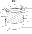
- the height h of the hollow body 3 is defined between the bearing surface 32 and an uppermost end, here formed by a top flange 5.
- Such height h may be substantially equal to total height H1 of the container 1 as only a thin flexible lid 20 overlies the top flange 5 (difference H1-h being for instance less than 100 ⁇ m, or less than 1% of height H1, for example from 20 to 40 ⁇ m, preferably from 25 to 40 ⁇ m.
- the hollow body 3 is here made of plastic material, typically a single plastic material, for example thermoplastic material, and can be browned. It can be obtained form example blow molding an injected preform, typically an injected preform, or by extrusion blow molding. In these cases, as illustrated in Fig. 3 , at least one cutting operation may be performed in a pre-container 40 to define a top opening O1, so that the side wall 30 has a tubular shape of relatively wide section. The top opening O1 is also relatively wide as compared to the maximal radial size, here diameter D1 (see Fig. 5 ), of the hollow body 3.
- the top opening O1 is to be interpreted as wide opening due to a diameter or equivalent characteristic size superior or equal to half (or possibly superior or equal to three quarters) of the diameter D1 or similar radial size measured at a maximum of section of the side wall 30 of the body 3.
- the thermoplastic material for the body 3 is polyethylene terephthalate (PET).
- PET polyethylene terephthalate
- PET has certain very advantageous properties of bodies made from this material (namely their good mechanical resistance, the facility to be filled with a hot liquid or substance, the good transparency of the PET which does not adversely affect the appearance of the content, a relatively good barrier effect to oxygen). Also PET containers can benefit from appropriate recycling streams.
- the top opening O1 of the body 3 is delimited by an inner rim 5b having a circumference lower than circumference of the top 31.
- the body 3 is provided with a top flange 5 that protrudes radially inward from the top 31 of the side wall 3.
- the top flange 5 and the bottom 4 correspond to opposite ends of the body 3, and extend each transversally with respect to the longitudinal axis X.
- the inner rim 5b may extend in a horizontal opening plane, while the upper portion 301 of the side wall 30 is substantially vertical or slightly tapering (for instance with a tapering at about 5-25° from the vertical), in a progressive manner, toward the top flange 5.
- the interior face of the annular upper portion 301 is smooth, without any relief.
- the side wall 30 has a flat longitudinal profile, at least in the upper portion 301 and such flat longitudinal profile may extend at least 10 mm, preferably at least 20 mm downwardly from the outer rim 5a of the top flange 5.
- the inner rim 5b may extend at slightly lower height level than the outer rim 5a, due to angle a5' formed between the lower face 15a of the top flange 5 and a horizontal plane intersecting the top 31 of the annular side wall 30.
- Figs 2A and 2C it can be seen that the angle a5' is formed when the container 1 is in a sealed state, while a bigger angle a5 is formed at same location before the sealing by the top lid 20.
- the side wall 30 is a thread-less and neck-less side wall.
- the top opening O1 defines an opening diameter D in an opening plane which is at least equal to 35 or 40 mm, while maximal radial extension Lt of the top flange 5 is less than 5.0 mm, preferably inferior or equal to 4.0 mm. Such radial extension Lt is measured in the opening plane, between the outer rim 5a and the inner rim 5b. The radial extension Lt is optionally constant.
- the top opening O1 may be intersected by the longitudinal axis X and allows content of the container 1 to be retrieved by the consumer. Referring to Fig. 1 or 6 , it can be seen that this top opening O1 is typically a particularly wide opening, having typically a diameter D or similar characteristic radial size superior to 35 or 40 mm. This may be advantageous to allow a spoon to be introduced in an interior volume V through the top opening O1.
- Such wide top opening O1 is required when using the container 1 for receiving a scoopable solid (as opposed to powder), liquid or viscous fluid, composition, for example food composition, for example wet composition, where use of a spoon is convenient for efficiently retrieving the content.
- the base 32 of the bottom 4 is not necessarily as wide as the inner rim 5b of the top flange 5.
- the annular base 32 shown in Fig. 3 forms a bearing surface of smaller size than the top opening O1.
- the cutting operation to obtain the opening O1 may be performed by transversally cutting a pre-container 40 or a bottle-like piece, which is blow molded from a preform (not shown).
- the cutting is preferably performed at at least one groove designed for this, so as to form the top opening O1 of the hollow body 3.
- PET is advantageously used to define the hollow body 3. Indeed, PET is of interest to maximise material performance per gram in the stretched area. PET is of interest due to high scale (preforms), link into PET industry roadmap, recyclability, transparency with high quality (better than polypropylene or polyethylene for instance).
- the container 1 is provided with a flexible top lid 20 of suitable size and shape to close the top opening O1.
- the flexible top lid 20 is arranged in sealing contact with the upper face 15b of the top flange 5, namely in annular contact in an annular contact formed entirely above the side wall 30.
- Such top flange 5 may be crown-shaped.
- the flexible top lid 20 forms here a single foil sealing system, only comprising a sealing foil that is fixed to the upper face 15b of the top flange 5, in order to seal the top opening O1.
- An appropriate cut is performed to define an outer shape of the sealing foil.
- the sealing foil may be a one-piece foil of material suitable for food contact. The material allows the sealing foil to be bendable.
- the material or foil is comprised of paper or plastic and/or associations thereof, eventually in association with aluminium. In a preferred embodiment the material and/or of foil is metal-free. Typically, the material and/or foil has low water permeability, is approved for food contact and is not flammable.
- maximal thickness of the top lid 20 is comprised between 20 and 50 ⁇ m for instance, and preferably between 25 and 40 ⁇ m.
- the top lid 20 is optionally provided with a pull tab PT.
- the pull tab PT is here integrally formed with the flexible top lid 20. Easier removal of the flexible top lid 20 is obtained when pinching the pull tab PT that is entirely offset (radially outward) with respect to the top opening O1.
- the flexible top lid 20 adheres to the top flange 5, using an adhesion force inferior to a tearing force required to tear the top lid 20.
- the top lid 20 is thus entirely removable without tearing from the annular top flange 5 or similar top portion when pulling the pull tab PT or similar peripheral portion. In other words, no lid material remains affixed to the hollow body 3 when the top of the container is fully open. Easy separation from the body 3 is of interest for disposal of the body 3, which is typically highly suitable for recycling and economical valorization.
- the flexible top lid 20 does not significantly protrude radially outwards as compared to the side wall 30, as illustrated in Fig. 1 for instance, and more precisely, it is understood that the annular outer edge 25 of the flexible top lid 20 may remain substantially parallel to the outer rim 5a of the top flange 5, thus not extending radially beyond 2.0 mm, preferably not beyond 1.0 mm from such outer rim 5a (except in region of the optional pull tab PT). In one embodiment, not represented, the annular outer edge 25 of the flexible top lid 20 does not extend beyond the outer rim 5a of the top flange 5 (except in region of the optional pull tab PT). As such the flexible top lid 20 would cover only partially the top flange 5 (for example not covering an external margin area of the top flange 5, except in region of the optional pull tab PT if present).
- Fig. 1 shows the pull tab PT defined as an extension locally protruding beyond an annular outer rim 5a of the top flange 5 defined at the top 31 of the side wall 30.
- the pull tab PT of course has an outer rim that represents a margin part of the full circumference of the top lid, for example less than a quarter or less than a fifth of the full circumference of the top flange 5. Besides, the following relation may be satisfied: L1/P5 ⁇ 1/5
- the top flange 5, of annular shape may be an inner flange. Indeed, there is typically no outer relief at the top part of the body.
- the top flange 5 is provided with an inner edge 5b, proximal to the longitudinal axis X, radially offset inward as compared to the side wall 30.
- the bulk of the container 1 is not perceived as thin and trays may be filled with the containers 1 without significant space between the containers, unlike containers having outer flanges or similar collars.
- the container 1 may be more compact.
- the bodies 3 are designed to maximize amount of content/product per tray and/or per pallet.
- the top flange inner rim 5b has a cut edge obtained by a cut performed in a transverse direction.
- the inner rim 5b may form a thinned part of the top flange 5, opposite to a thick part closer to the side wall 30.
- the top flange 5 of annular shape may have a radial size or extension Lt, measured between the outer rim 5a and the inner rim 5b along the opening plane.
- radial extension Lt is typically less than 5.0 mm, preferably inferior or equal to 4.0 mm.
- the top lid 20 has an adhering ring portion 22 (in contact with the top flange 5, including the outer edge 25 and surrounding the central portion 21) provided with a radial extension not superior to 5 mm.
- the outer edge 20b of the top lid 20 may be defined in a margin portion that overlies the top flange 5, as illustrated in Fig. 1 .
- an adhering ring portion 22 (see Fig. 2 ) may also be a circumferential margin portion of same extension as compared to extension of the top flange 5, as measured in any longitudinal plane parallel to the longitudinal axis X.
- the adhering ring portion 22 is fixed on the upper face 15b that extends without any significant relief. As illustrated in Fig. 2 , the pull tab PT extends beyond an outer limit of the adhering ring portion 22.
- one of the following relations is satisfied: 1.0 mm ⁇ Lt ⁇ 5.0 mm, preferably 1.5 ⁇ Lt ⁇ 4.0 mm, preferably 2.0 ⁇ Lt ⁇ 3.0 mm.
- the ratio Lt/D may be inferior to 1:10.
- a flat annular surface portion may be formed, and radial extension of such flat annular surface portion (i.e., surface portion without any change of curvature) may be about 2 mm.
- Corresponding thickness in the top flange 5 may be comprised between 400 and 600 ⁇ m.
- the top flange 5 is slightly tapering upwardly, so that a shallow angle a5' is defined between a horizontal plane perpendicular to the longitudinal axis X and the upper face 15b of the top flange 5.
- the angle a5' is typically inferior or equal to 7 or 9°, preferably strictly inferior to 6°, so that height of the top flange 5 is minimized.
- the hollow body 3 is typically semi-rigid, for example as rigid as plastic bottles containing gaseous water or sodas
- the body 3 may be provided with an annular part Z3 that acts as a hinge at a junction between the top flange 5 and the top 31 of the side wall 30, i.e. in a region adjacent to the outer rim 5a.
- the top flange 5 may be slightly movable axially inwards. This prevents formation of cracks and provides a damping effect, at least with respect to vertical load, suitable to prevent accidental leaks at or around the top opening O1.
- the hinge effect is only of low amplitude, as plastic material of the hollow body 3 is significantly more rigid than the foil material used for the flexible top lid 20.
- the side wall 30 has an upper portion 301, directly connected to the top flange 5, and a lower portion 302 tapering from the upper portion 301 toward the bottom 4, in a curved manner as clearly apparent in the Fig. 1 .
- the bearing surface 32 formed at the bottom 4 may be circular or may optionally define a non-circular shape for the base opening 32, while defining a substantially planar bearing surface for stability purposes. More generally, the side wall 30 may be provided with any ring-shape, either of circular cross-section, or including one or more portions with non-circular cross-sections or with non-symmetric shape.
- the sleeve 10 may be added by an in-mold labelling method or the like, or added after the molding of the body 3.
- the outer face of the annular upper portion 301 is smooth, without any relief.
- the upper portion 301 is particularly useful for displaying information and can be typically covered by a rectangular shaped strip or sleeve 10 arranged in a form of a sleeve label. It is also compatible with e.g. inline digital printing.
- the side wall 30 may define a top opening O1 of higher diameter D than the corresponding size defined at the annular bearing surface 32.
- Such configuration is obtained in Figs 1 and 3 by use of the specific lower portion 302, which tapers downwardly, preferably in a curved manner. With such configuration, the content is easy to retrieve by use of a spoon, especially when a circular cross-section or a continuously rounded cross-section is provided in the bottom 4 and in the lower portion 302.
- the bearing surface 32 may be larger than the top opening O1.
- the side wall 30 may be continuously curved in a convex manner (as perceived from outside the container 1), from the top 31 to the bearing surface 32 forming the outer limit of the bottom 4. This option may be of interest to reduce overall height H1 of the container 1.
- the side wall 30 of the hollow body 3 may advantageously be provided with an upper portion 301 of cross sections of an increasing size with increased spacing from the top flange 5. With such configuration, a cylindrical portion or a bulge 30c may optionally be provided at a distance from the top 31.
- the maximal outer diameter or similar greater dimension D1 of the body section, as measured perpendicularly to the longitudinal axis X, is preferably such that the ratio D/D1 remains superior to 1:2. More generally the following relation may be satisfied: 0.70 ⁇ D/D1 ⁇ 0 .97 .
- the greater dimension D1 is not necessarily measured in a bulge 30c as in Fig. 1 and may be, for instance, a diameter of a cylindrical portion.
- the upper portion 301 may proportionally taper less, upwardly, than the lower portion 302 is tapering, downwardly.
- the annular side wall 30 optionally comprises a peripheral bulge 30c at a junction between the upper portion 301 and the lower portion 302.
- the annular side wall 30 comprises a bulge 30c having a circular cross section and maximal width of the upper portion is defined at the bulge 30c.
- Such bulge 30c may be of interest to prevent any slippage (downwardly or upwardly slippage) of a wrapping element or similar decorative banderol, without the need of forming an axial abutment shoulder or similar reliefs for maintaining such element.
- the flexible top lid 20 is adapted to prevent use of any rigid cap or other cap means above the body 3.
- the flexible top lid 20 is thus the outermost upper element of the container 1 and may be directly used to form the primary surface for decoration. Digital inline printing or any kind of marking may be performed to define label information and/or decorative elements on the top surface S20 of the top lid 20.
- the top surface S20 is of interest to provide a hollow body 3 that remains unwrapped and unmarked with printing material, whereby the body 3 is left "pure" for a better recyclability.
- the one piece hollow body 3 thus may entirely define the outer face of the side wall 30, without need for additional layer or marking material.
- the production method may also be simple as no labelling is required around the body side wall 30.
- FIGs 2A-2C , 3 , 6 and 7A-7B and 8 some non-limiting examples of making containers 1 are described.
- hollow bodies 3 may be each obtained from a plastic piece defining a pre-container 40, here having a single opening 40a. It is understood that the pre-container 40 may be produced as an optimized intermediary blow-molded piece, ready to be cut, preferably by trimming, thanks to a circumferential groove 47 (shown in Fig. 8 when the open section 41 of the pre-container 40 has not been trimmed yet) or similar relief facilitating the cut. Fig. 3 shows the two complementary parts of the pre-container 40 after such cut.
- a circumferential flange extending inwardly from the corresponding annular end (top 31) of the side wall 30 is defined during a cutting step, preferably a trimming step.
- the top flange 5 in an unsealed state is thus obtained.
- a cutting element may be inserted through the pre-container sidewall at the bottom line BL of the groove 47, so as to perform the trimming.
- a longitudinal profile of the circumferential groove 47 suitable to define the top flange 5 after the cutting, preferably trimming.
- the part intended to form the top flange 5 is tapering upwardly, so that a shallow angle a5 is defined between a cut plane CP1 perpendicular to the longitudinal axis X and the upper face 15a of the top flange 5.
- the angle a5 is typically between 5° and 20°, preferably between 10° and 20°, so that height H5 of the top flange 5 in the unsealed state is minimized.
- Such height H5 may be inferior to 2.0 or 3.0 mm and the ratio H5/H1 is preferably inferior to 2/100 or 3/100.
- the pre-container 40 is obtained in a mold.
- Such pre-container 40 may be produced by means of blow molding a preform containing PET or similar polymer plastic material.
- the method to obtain the pre-container 40 may be an injection blow molding method for example an injection stretch blow molding method (both being referred to as I(S)BM), or an extrusion blow molding method (EBM).
- I(S)BM injection stretch blow molding method
- EBM extrusion blow molding method
- Such method is suitable to produce a pre-container 40 having a first end provided with a single opening 40a (optionally a narrow opening of greater size as compared to the top opening O1).
- the pre-container 40 When ejected from the blow molding machine, the pre-container 40 is provided with a bottom section and a section 41 having an open end.
- the open section 41 optionally includes a neck 41a and a shoulder 41b.
- the bottom section forms the hollow body 3 and extends longitudinally around the central axis.
- the central axis typically defines a longitudinal stretching axis.
- the average thickness of the pre-container sidewall may be typically inferior to 450 ⁇ m, preferably 400 ⁇ m, preferably 300 ⁇ m.
- the preform may also be elongated or provided with a tapering toward the lower end, in order to obtain a pre-container 40 of reduced thickness both in an upper portion and in a lower portion of the side wall.
- preform may be of interest to have a longitudinal stretching ratio inferior to the radial stretching ratio, which is often preferred to optimally reduce amount of plastic material in the pre-container sidewall.
- such groove 47 may be at least twice as great in width D45 as compared to height H5 (illustrated in Fig. 2A and 8 ) initially defined between the outer rim 5a and the inner rim 5b of the top flange.
- Such circumferential groove 47 may have a V-shape longitudinal profile in the sidewall.
- the V-shape is defined with a determined apex angle also called the aperture angle b45, which is typically comprised between 10° and 40°, as measured in any longitudinal plane parallel to the central axis.
- Such aperture angle is twice the angle a5 obtained after a trimming when the groove has a symmetrical V-shape profile.
- the angle a5 shown in Fig. 2A is greater than final angle a5' obtained after the sealing of the flexible top lid 20.
- the angle a5 is between 5° and 20°, preferably between 10° and 20°, preferably between 13° and 17°.
- the trimming at the bottom line BL of the groove 47 is performed using suitable trimming equipment.
- a rotation movement may be used for the cutting edge or for the pre-container 40.
- the one or more blades used for the trimming are extending transversally relative to the central axis.
- the open section 41 of the pre-container 40 is cut away and the hollow body 3 is retrieved.
- the open section 41 is internally recycled (which means zero industrial scrap).
- Rotation of the elongated pre-container 40 along a cutting element may optionally be limited to the diameter or circumference required for fully cutting the plastic material at a bottom line of the groove, which prevents the generation of chips or plastic particles.
- the cutting element may be a non-heated cold knife, possibly with a resharpenable blade.
- the trimming operation may be implemented in various manners. It is understood such trimming operation may be performed at high rate of production.
- the trimming step may be followed by a filling step and a sealing step for sealing the flexible top lid 20, which allows the container 1 to be closed in tight manner.
- the wide top opening O1 is advantageous for fast filling of the content.
- a single filling may be performed as the hollow body 3 defines a single compartment.
- the flexible top lid 20 can be sealed axially to cover the top opening O1, after the filling.
- the top opening O1 may be advantageously circular as a better sealing, with great homogeneity, can be obtained.
- the flexible lid here a top lid 20, essentially consists of paper, plastic, or association of such materials, for example a PET material, preferably metal-free.
- the flexible lid 20 may be deprived from any metallic foil, the flexible lid 20 being preferably a metal-free film for purpose of recyclability.
- the outer rim 5a of the flange 5 has, at least before the sealing, a determined thickness e5a comprised between 400 ⁇ m and 600 ⁇ m.
- a determined thickness e5a is sufficient to obtain a hinge effect at annular region Z3 shown in Figs 2A and 4 .
- Such hinge effect prevents cracks to be formed, especially when pressure applied onto the flange is subject to repeated variations.
- the flange 5 is tapering upwardly (at least before the sealing of the flexible top lid 20), so as to define the angle a5, here a slope angle between 5° and 20°, preferably between 10° and 20°, to the horizontal at the ring portion 22.
- the slope angle a5 in unsealed state of the flange 5) is between 13° and 17°, for example 15°.
- the horizontal typically coincides with the top opening O1 (in normal upstanding position of the container 1 as illustrated in the drawings).
- the top opening O1 may not extend in a horizontal plane but the longitudinal axis X is vertical or substantially vertical (in normal upstanding position of the container 1).
- the flange 5 of the body 3 is provided with an exterior face, here the upper face 15b, having a flat portion of annular shape.
- "Flat” here means that the longitudinal profile (as perceived in any longitudinal plane including the longitudinal axis) is straight in the flat portion.
- the radial width rw of such flat portion of the upper face 15b is of at least 1.5 mm, preferably at least 2 mm, before the sealing.
- Fig. 8 shows such straight profile in the upper face 15b of the top flange 5, before the sealing.
- the radial width rw' (shown in Fig. 2C ) of the flat portion in the upper face 15b may be also superior or equal to 1.5 mm after the sealing.
- the ring portion 22 may be less angled after the sealing.
- the flat portion may form a first portion FP1 distal from the inner rim 5b, which is formed in a second portion FP2 of the flange 5, which is typically horizontal (perpendicular to the longitudinal axis X).
- the first portion FP1 may extend parallel or nearly parallel to the second portion FP2 (adjacent to the first portion FP1).
- the second portion FP2 may be a horizontal edge portion (on the inner side of the top flange 5) that is horizontal before and after attachment of the top lid 20, while the first portion FP1 is sloped (with angle a5) at least before the sealing.
- the outer rim 5a is formed where there is a minimum radius of curvature in the longitudinal profile of the hollow body 3, such a radius of curvature RC being here comprised between 1.0 and 2.0 mm (at the outer rim 5a), before the sealing by the top lid 20.
- a radius of curvature RC being here comprised between 1.0 and 2.0 mm (at the outer rim 5a), before the sealing by the top lid 20.
- the flat portion FP1 forms or is part of the ring portion 22 that is heated during the sealing. This is of interest to have efficient sealing, especially when PET material is involved.
- the hollow body is in PET and the flange 5 has a radial extension Lt superior or equal to 2.0 mm, preferably 2.5 mm, and inferior or equal to 5.0 mm.
- the radial extension Lt is typically measured in a plane (for instance the opening plane) perpendicular to the longitudinal axis X.
- a sealing head 50 suitable for the sealing step, may be provided with a front face 51 having a central portion 51a provided with vacuum apertures and an annular portion (heating ring 51b) adapted to transmit heat to the top flange 5 and to the crown-shaped or disc-shaped margin portion 22 of the flexible top lid 20.
- the sealing head 50 provides a vacuum to pick & release the flexible lid 20, and a heating ring to activate the sealing.
- the heating ring 51b in the sealing head 50 may form a metal part and is here designed to operate at a diameter d' that is greater than diameter D of the top opening O1. It is typically done by the sealing head 50 pushing linearly, for instance vertically, onto the upper face 15b. The front face 51 is thus facing the upper face 15b of the top flange 5.
- the position of the flexible top lid 20 is adjusted in a centered manner to cover the front face 51 and can exactly be pushed, by the heating ring 51b (without offset), onto an annular region between the outer rim 5a and the inner rim 5b of the top flange.
- the flat portion of the ring portion 22 can be pressed and heat.
- the sealing of the lid 20, here a flexible top lid is performed by applying the sealing head 50 at a temperature that may be maintained at a temperature level comprised between 140°C and 200°C.
- the sealing can be divided into at least two sealing sub-steps, preferably from two to four sealing sub-steps. For instance, in order to seal the top lid 20 onto the upper face 15b of the top flange 5, a pushing action from the sealing head 50 may be repeated, with two, three, four or five repetitions.
- top flange 5 may oscillate between a pressed state and a release state (which optionally corresponds to a state with a lower pressure from the sealing head).
- the slope formed by the top flange 5 is decreased. For instance the angle a5 of about 15° +/- 5° being converted into a final angle a5' of about 4° +/- 3°.
- the top flange 5 is made of PET, preferably semi-crystalline PET.
- the sealing is performed by at least two pushing actions from the sealing head 50.
- the sealing of the flexible lid 20 involves PET material at the ring portion, it is typically performed with a variation of pressure values for the contact. This is due to relative movement between the sealing head 50 and the hollow body 3. Hinge effect at hinge area Z3 is of interest to keep perfect integrity of the body 3, here a PET body.
- the slope angle a5 (formed in unsealed state of the flange 5) is decreased in this manner, progressively, to the lower angle value a5' corresponding to the final angle in sealed state.
- the flange 5 has here a maximum thickness e5, which is typically located in region of the ring portion 22 provided with flat surface portion, for contact with the sealing head 50.
- the maximum thickness e5 is preferably at least 400 ⁇ m and may be higher than an average thickness e of the side wall 30, preferably at least 100 ⁇ m higher.
- the flexible top lid 20 is sized and shaped so that only one pull tab PT of the lid is laterally shifted away from the active face of the sealing head. As a result, the pull tab PT is not adhered to the body 3 and radially protrudes outward to be laterally shifted relative to the annular top 31 of the side wall 30. After the sealing, the annular outer edge 20b of the flexible lid 20 extends not beyond 1 mm (except in region of the pull tab PT) from the outer rim 5a of the top flange 5 having the final slope as illustrated in Fig.
- the top flange 5, as obtained after the sealing, may be provided with a low radius of curvature RC' in the region adjacent to the top 31 of the annular side wall 30.
- the radius of curvature RC' may be lower than 2 mm and is here slightly lower than the corresponding radius of curvature RC before sealing.
- the radius of curvature RC of the container outer face may be comprised between 1 and 2 mm, for example about 1.5 mm. Such radius of curvature is measured in a plane parallel to the longitudinal axis X and intersected by the longitudinal axis X.
- sealing head 50 illustrated in Fig. 7A may be arranged in the longitudinal direction to seal the flexible top lid 10, other configurations may be used, for instance with small tilting of the sealing head 50.
- the top flange 5 can optionally be tilted (at a small angle relative to the horizontal plane) in some variants.
- the fixing step may be performed by a tool moving the sleeve 10 from a direction opposite to the top of the container 1, or more generally opposite to the flexible lid 20.
- the decorative sleeve is thus adhered to the side wall 30 after being transported longitudinally from the bottom side, preferably at an axial distance from the annular bearing surface 32 of the bottom 4.
- the container 1 can be used for product comprising the container and a content in the container. Thus at least a part of an interior volume V of the container is filled with a content.
- the container can be a packaging element of the content, useful to transport, protect, preserve, and/or otherwise procure said content.
- the content can be any kind of content to be procured to a user, for example a consumer, in moderate quantities.
- the content can for example a food or beverage composition, a drug, a personal-care composition, a home-care composition, a home improvement composition, a toy, a small part good.
- Examples of personal care compositions include hair care compositions such as shampoo compositions, conditioner compositions or hair coloring compositions, skin compositions such soap compositions, body wash compositions, sun protection compositions, hydrating compositions or anti-aging compositions, and make-up compositions.
- hair care compositions such as shampoo compositions, conditioner compositions or hair coloring compositions
- skin compositions such soap compositions, body wash compositions, sun protection compositions, hydrating compositions or anti-aging compositions, and make-up compositions.
- home-care compositions include, fabric care compositions such as laundry compositions or softener compositions, dish-washing compositions such as manual dish washing compositions or automatic dish washing compositions, hard-surface cleaning compositions, such as kitchen cleaning compositions, bathroom cleaning compositions, wood floor cleaning compositions or tiles cleaning compositions.
- Examples of home improvement compositions include paints, glues, plasters or cements compositions.
- Examples of small parts goods include nails, screws and the like.
- Food or beverages are compositions that are to be orally consumed. This can be in various forms including liquid, viscous semi-fluid, or solid, optionally as a powder.
- the food can be a spoonable viscous semi fluid composition or spoonable solid. It can be for example or scoopable solid, as opposed to a spoonable powder.
- the beverage can be water, carbonated or non-carbonated, non-alcoholic beverages (also referred to as soft drinks), carbonated or non-carbonated, alcoholic beverages, carbonated or non-carbonated, milk or vegetal milk substitutes.
- the food can be cereals, dairy compositions, vegetal dairy substitute compositions, deserts compositions such as creams, mousses, gels, puddings, icecreams compositions, fruits, vegetables, or fruit or vegetables compositions for example whole fruits or whole fruit parts, fruit purees or jams, meat of meat substitutes, confectionary compositions, sauces compositions, soups compositions, infant nutrition compositions, medical nutrition compositions, coffee creaming or whitening compositions, coffee or chocolate compositions, for example instant coffee or chocolate, or other grocery compositions.
- dairy compositions vegetal dairy substitute compositions
- deserts compositions such as creams, mousses, gels, puddings, icecreams compositions
- fruits, vegetables, or fruit or vegetables compositions for example whole fruits or whole fruit parts, fruit purees or jams
- meat of meat substitutes confectionary compositions
- sauces compositions soups compositions
- infant nutrition compositions infant nutrition compositions
- medical nutrition compositions coffee creaming or whitening compositions
- coffee or chocolate compositions for example instant coffee or chocolate, or
- the food can be a frozen composition, chilled or fresh, typically with a storage at a temperature of from 0°C to 10°C, or long shelf ambient temperature food, typically with a storage at a temperature of higher than 15°C.
- the food is a wet food compositions, comprising substantial amounts of moisture or water, as opposed to dehydrated food compositions, for example at least 20% by weight, or at least 30% by weight, or at least 40% by weight, or at least 50% by weight, or at least 60% by weight, at least 80% by weight.
- Such compositions can be more sensitive to contaminations and a high resistance sealing, for example with a high vacuum leak resistance can be appropriate.
- Dairy compositions or vegetal dairy substitute compositions typically comprise of dairy material or a dairy substitute material.
- dairy or “milk” can encompass vegetal substitutes, for example based on soy, oats, almond, rice, coconut and mixture thereof.
- the dairy composition can be for example a dessert, a fermented dairy composition such as yogurt or kefir, a cheese, butter.
- the dairy material is typically comprised of milk and/or ingredients obtained from milk. It is also referred to as a "milk-based composition".
- milk encompasses animal milk, such as cow's milk, and also substitutes to animal milk, such as vegetal milk, such as soy milk, rice milk, coconut milk, almond milk, oats milk etc...
- Dairy compositions are known by the one skilled in the art of dairy products, preferably of fermented dairy products.
- a milk-based composition encompasses a composition with milk or milk fractions, and compositions obtained by mixing several previously separated milk fractions. Some water or some additives can be added to said milk, milk fractions and mixtures.
- the milk is animal milk, for example cow's milk. Some alternative animal milks can be used, such as sheep milk or goat milk.
- the milk-based composition can typically comprise ingredients selected from the group consisting of milk, half skimmed milk, skimmed milk, milk powder, skimmed milk powder, milk concentrate, skim milk concentrate, milk proteins, cream, buttermilk and mixtures thereof. Some water or additives can be mixed therewith. Examples of additives that can be added include sugar, sweeteners, fibers, and texture modifiers.
- Fermented dairy compositions typically comprise bacteria, preferably lactic acid bacteria, preferably alive. Appropriate bacteria for fermentation are known by the one skilled in the art. It is mentioned that lactic acid bacteria are often referred to as ferments or cultures or starters.
- the lactic acid bacteria preferably comprise, preferably essentially consist of, preferably consist of, Lactobacillus delbrueckii ssp. bulgaricus (i.e. Lactobacillus bulgaricus) and Streptococcus salivarius ssp. thermophilus i.e. (Streptococcus thermophilus) bacteria.
- the lactic acid bacteria used in the invention typically comprise an association of Streptococcus thermophilus and Lactobacillus bulgaricus bacteria. This association is known and often referred to as a yogurt symbiosis.
- Fermented dairy compositions are typically obtained by a process involving a fermentation step with at least one lactic acid bacteria.
- the dairy material is inoculated with the lactic acid bacteria, and the mixture is then allowed to ferment at a fermentation temperature.
- Such inoculation and fermentation operations are known by the one skilled in the art.
- the lactic acid bacteria produce lactic acid and thus cause a pH decrease.
- the fermentation temperature can be of from 30°C to 45°C, preferably from 35 °C to 40 °C, with a pH decrease to a breaking pH at which proteins coagulate to form a curd.
- the breaking pH is preferably of from 3.50 to 5.50, preferably of from 4.0 to 5.0, preferably from higher than 4.5 to 5.0.
- the containers 1 may be grouped in a food pack.
- a wrapping element made of cardboard or plastic may be used for packing the containers 1 in two rows.
- the wrapping element such as disclosed in document EP 0461947 , may define a top panel, a bottom panel and at least two side panels. Spacing elements, for example a beam member or folded members, may be optionally provided to maintain the containers in parallel rows.
- such food pack may be provided with at least one row of containers.
- the covering element may be used to group at least two containers, for example by defining respective cavities for receiving with a small play the lower parts of the containers 1.
- the container 1 can be for example a container having a capacity of, or containing a content of a volume of (or mass of) of 50 ml (or 50 g), to 1 L (or 1 kg), for example a container of 50 ml (or 50 g) to 80 ml (or 80 g), or 80 ml (or 80 g) to 100 ml (or 100g), or 100 ml (or 100 g) to 125 ml (or 125 g), or 125 ml (or 125 g) to 150 ml (or 150 g), or 150 ml (or 150 g) to 200 ml (or 200 g), or 200 ml (or 200 g) to 250 ml (or 250 g) or 250 ml (or 250 g) to 300 ml (or 300 g), or 300 ml (or 300 g) to 500 ml (or 500 g), or 500 ml (or 500 g) to 750 ml (or
- the present invention has been described in connection with the preferred embodiments. These embodiments, however, are merely for example and the invention is not restricted thereto.
- the top flange 5 used for the containers 1 shown in Figs 1 and 3 is not necessarily provided with a circular edge. Other shapes, including straight edge portions may be used.
- the side wall 30 does not necessarily always extend regularly around a longitudinal axis X, here illustrated as a symmetry axis. Of course, the side wall 30 may be provided with a longitudinal irregular profile and/or significant curves, possibly with at least one oblique gripping part or oblique shoulder.
Landscapes
- Engineering & Computer Science (AREA)
- Mechanical Engineering (AREA)
- Ceramic Engineering (AREA)
- Closures For Containers (AREA)
Claims (13)
- Verfahren zum Verschließen eines Behälters (1) an einem ringförmigen Ende davon, wobei das Verfahren die folgenden Schritte umfasst:- Bereitstellen eines Hohlkörpers (3), der eine sich um eine Longitudinalachse (X) erstreckende Seitenwand (30) und einen mit einer ringförmigen Oberseite (31) der Seitenwand (30) verbundenen Flansch umfasst, wobei der Flansch (5) eine axiale Öffnung (O1) des Behälters umgibt und ein Innenflansch ist, der von der ringförmigen Oberseite (31) bis zu einem ringförmigen Innenrand (5b) radial einwärts vorsteht;- Thermoversiegeln eines flexiblen Deckels (20) auf dem Flansch (5), um die Öffnung (O1) zu schließen, indem der flexible Deckel (20) mit einem Ringteil (22) des Flansches (5) axial in Kontakt gebracht, gedrückt und erwärmt wird; wobei der Flansch (5) eine radiale Ausdehnung (Lt) größer oder gleich 2,0 mm, vorzugsweise größer oder gleich 2,5 mm, und kleiner oder gleich 5,0 mm aufweist, gemessen zwischen dem ringförmigen Innenrand (5b) und einem ringförmigen Außenrand (5a) benachbart zu der ringförmigen Oberseite (31) der Seitenwand (30), und wobei sich der ringförmige Innenrand (5b) senkrecht zur Longitudinalachse (X) erstreckt, wobei sich der Flansch (5) zumindest vor dem Thermoversiegeln des flexiblen Deckels (20) aufwärts verschmälert, um einen Neigungswinkel (a5) zwischen 5° und 20°, vorzugsweise zwischen 10° und 20°, zu einer Ebene senkrecht zur Longitudinalachse (X) am Ringabschnitt (22) zu bilden und dadurch gekennzeichnet, dass der Hohlkörper (3) aus PET ist und dass der flexible Deckel (20) aus Papier oder Kunststoff besteht und nur an einer Oberseite (15b) des Flansches (5) in ringförmigem Kontakt mit dem Hohlkörper (3) steht, wobei dieser ringförmige Kontakt vollständig oberhalb der Seitenwand (30) ausgebildet ist, wobei der flexible Deckel (20) in versiegeltem Kontakt mit der Oberseite (15b) des Flansches (5) angeordnet ist.
- Verfahren nach Anspruch 1, wobei das Thermoversiegeln nach dem Füllen eines Innenvolumens (V) des Hohlkörpers (3) mit einem Inhalt durchgeführt wird, wobei der Hohlkörper (3) ein einstückiger Körper ist, der einen Boden (4) gegenüber der einzigen Öffnung (O1) aufweist, die eine obere Öffnung (O1) des Hohlkörpers (3) ist, wobei der Flansch ein oberer Flansch (5) ist.
- Verfahren nach Anspruch 2, wobei das Thermoversiegeln durch Verwenden eines flexiblen oberen Deckels (20) aus Folienmaterial durchgeführt wird, und wobei der flexible obere Deckel (20) eine Zuglasche (PT) aufweist, die beim Thermoversiegeln des flexiblen oberen Deckels (20) auf den oberen Flansch (5) lateral relativ zum oberen Flansch verschoben wird.
- Verfahren nach einem der vorhergehenden Ansprüche, wobei der Flansch (5) mit einer Außenfläche bereitgestellt wird, die einen flachen, ringförmigen Abschnitt mit einer radialen Breite (rw) von mindestens 1,5 mm vor dem Thermoversiegeln, vorzugsweise mindestens 2,0 mm, aufweist, und wobei der flache Abschnitt den Ringabschnitt (22), der während des Thermoversiegelns erhitzt wird, bildet oder Teil davon ist, und/oder
wobei der Hohlkörper (3) ein Longitudinalprofil mit einem am ringförmigen Außenrand (5a) ausgebildeten Krümmungsradius (RC) aufweist, der vor dem Thermoversiegeln 1,0 bis 2,0 mm beträgt. - Verfahren nach einem der vorhergehenden Ansprüche, wobei der ringförmige äußere Rand (5a) des Flansches (5) zumindest vor dem Thermoversiegeln eine festgelegte Dicke (e5a) aufweist, die zumindest gleich 400 µm und nicht größer als 600 µm ist.
- Verfahren nach einem der vorhergehenden Ansprüche, wobei der Flansch (5) eine maximale Dicke (e5) aufweist, die größer ist als eine durchschnittliche Dicke (e) der Seitenwand (30), vorzugsweise mindestens 100 µm, wobei die maximale Dicke (e5) vorzugsweise mindestens 400 µm beträgt.
- Verfahren nach einem der vorhergehenden Ansprüche, wobei das Thermoversiegeln des flexiblen Deckels (20) durch Aufbringen eines Versiegelungskopf (50) bei einer Temperatur von 140 °C bis 200 °C durchgeführt wird, wobei das Thermoversiegeln vorzugsweise mindestens zwei Thermoversiegel-Teilschritte, vorzugsweise zwei bis vier Versiegel-Teilschritte beinhaltet.
- Verfahren nach Anspruch 7, wobei das Thermoversiegeln durch mindestens zwei Schiebeaktionen durch den Versiegelungskopf (50) durchgeführt wird, um den Neigungswinkel (a5), der im nicht versiegelten Zustand des Flansches (5) definiert ist, auf einen niedrigeren Winkelwert (a5') zu verringern, der im versiegelten Zustand des Flansches (5) definiert ist, und wobei vorzugsweise einer von dem Versiegelungskopf (50) und der Seitenwand (30) des Hohlkörpers (3) während des Thermoversiegelns wiederholt in zwei entgegengesetzte Richtungen verschoben wird, wobei mindestens eine Bewegung in einer der beiden entgegengesetzten Richtungen linear entlang eines Hubs durchgeführt wird, der vorzugsweise kürzer oder gleich der Höhe (H5) des Flansches (5) im nicht versiegelten Zustand ist.
- Verfahren nach einem der vorhergehenden Ansprüche, wobei der Neigungswinkel (a5) im nicht versiegelten Zustand des Flansches zwischen 13° und 17° ist.
- Verfahren nach einem der vorhergehenden Ansprüche, wobei der flexible Deckel (20) im Wesentlichen aus Papier, Kunststoff oder einer Kombination solcher Materialien, vorzugsweise aus teilkristallinem PET, besteht, wobei der flexible Deckel (20) von jeglicher Metallfolie frei ist.
- Verfahren nach einem der vorhergehenden Ansprüche, bei dem die Öffnung (O1) einen kreisförmigen Querschnitt aufweist und wobei der flexible Deckel (20) eine dem Boden (4) gegenüberliegende oberste Fläche des Behälters (1) bildet, wobei die Seitenwand (30) ohne jeglichen Hals und ohne jegliches Gewinde benachbart zu dem Flansch (5) ist.
- Verfahren nach einem der vorhergehenden Ansprüche, wobei das Thermoversiegeln des flexiblen Deckels (20) mit dem Hohlkörpermaterial des Ringteils (22) mit einer Variation der Druckwerte für den Kontakt aufgrund der relativen Bewegung zwischen dem Versiegelungskopf (50) und dem Hohlkörper (3) durchgeführt wird, mit einem Vakuumleckwiderstand von mindestens 0,2 mbar/mm2, vorzugsweise von 0,2 bis 2,0 mbar/mm2.
- Verfahren nach einem der vorhergehenden Ansprüche, wobei die Seitenwand (30) mit einer ringförmigen Ausbuchtung (30c) bereitgestellt ist, wobei die Seitenwand einen oberen Abschnitt (301) aufweist, der sich von der Ausbuchtung (30c) aufwärts zu dem Flansch (5) hin verschmälert, wobei der Flansch ein oberer Flansch (5) des Behälters (1) ist, und wobei die Seitenwand (30) zumindest in dem oberen Abschnitt (301), der benachbart zu dem oberen Flansch ist, ein flaches Longitudinalprofil aufweist, wobei sich der obere Abschnitt (301) mindestens 10 mm, vorzugsweise mindestens 20 mm, abwärts von dem ringförmigen äußeren Rand (5a) des oberen Flansches (5) erstreckt.
Applications Claiming Priority (1)
| Application Number | Priority Date | Filing Date | Title |
|---|---|---|---|
| PCT/IB2017/001731 WO2019130037A1 (en) | 2017-12-29 | 2017-12-29 | Sealing method using a thin flexible lid to hermetically close a wide opening, delimited by an inner flange, of a container, and container with an inner flange |
Publications (2)
| Publication Number | Publication Date |
|---|---|
| EP3732028A1 EP3732028A1 (de) | 2020-11-04 |
| EP3732028B1 true EP3732028B1 (de) | 2024-07-17 |
Family
ID=61188847
Family Applications (1)
| Application Number | Title | Priority Date | Filing Date |
|---|---|---|---|
| EP17840490.1A Active EP3732028B1 (de) | 2017-12-29 | 2017-12-29 | Versiegelungsverfahren unter verwendung eines dünnen flexiblen deckels zum hermetischen verschliessen einer breiten öffnung, begrenzt durch einen innenflansch |
Country Status (4)
| Country | Link |
|---|---|
| US (1) | US20200346414A1 (de) |
| EP (1) | EP3732028B1 (de) |
| CN (1) | CN111819066A (de) |
| WO (1) | WO2019130037A1 (de) |
Families Citing this family (7)
| Publication number | Priority date | Publication date | Assignee | Title |
|---|---|---|---|---|
| DK3747786T3 (da) * | 2019-06-04 | 2022-07-11 | Silver Plastics Gmbh & Co Kg | Emballagebakke med profileret tætningsrand |
| EP4122834B1 (de) * | 2020-03-16 | 2025-12-10 | Yakult Honsha Co., Ltd. | Heisssiegelvorrichtung |
| EP4032827A1 (de) * | 2021-01-20 | 2022-07-27 | L'oreal | Gespritzter behälter mit geringer wanddicke und schraubverschlussdeckel |
| WO2024049674A1 (en) * | 2022-08-31 | 2024-03-07 | Intercontinental Great Brands Llc | Container with sealing flange |
| USD1035358S1 (en) * | 2022-09-19 | 2024-07-16 | Ember Technologies, Inc. | Cup |
| US12049336B1 (en) * | 2023-02-10 | 2024-07-30 | Kingo Fruits Co., Ltd. | Vacuum-packed coconut, preparation method thereof, and ready-to-drink trimmed coconut |
| CN119748882B (zh) * | 2025-03-05 | 2025-05-02 | 上海宝柏新材料股份有限公司 | 一种可折叠塑料瓶的热熔焊接装置 |
Family Cites Families (13)
| Publication number | Priority date | Publication date | Assignee | Title |
|---|---|---|---|---|
| CH626561A5 (en) * | 1977-02-18 | 1981-11-30 | Gatrun Anstalt | Method for the manufacture of an assembly formed by a covering sheet and a support, device for implementing the method, and container obtained |
| JPH03176378A (ja) * | 1989-11-29 | 1991-07-31 | Showa Alum Corp | 食品密封包装用容器 |
| FR2663302B1 (fr) | 1990-06-14 | 1992-10-09 | Gervais Danone Sa | Dispositif d'emballage pour groupe d'objets. |
| US6547093B1 (en) * | 2000-02-28 | 2003-04-15 | General Mills, Inc. | Plastic container for food products |
| US6533136B1 (en) * | 2000-12-18 | 2003-03-18 | Owens-Illinois Closure Inc. | Sealing closure for extrusion blow molded containers |
| US20060191940A1 (en) * | 2005-02-25 | 2006-08-31 | Heyn William M | Sealing surfaces for container end panels |
| EP2364925A1 (de) * | 2010-03-10 | 2011-09-14 | Amcor Flexibles Kreuzlingen Ltd. | Behälter mit Verschlussmembran |
| CH704980A1 (de) * | 2011-05-19 | 2012-11-30 | Alpla Werke | In einem Streckblasverfahren hergestellter Kunststoffbehälter mit einem geschnittenen Hals. |
| WO2014170708A1 (en) * | 2013-04-15 | 2014-10-23 | Sa Des Eaux Minerales D'evian Saeme | Liquid filled bottle having a thin cover member provided with a flexible reinforcing element |
| WO2014182722A1 (en) * | 2013-05-06 | 2014-11-13 | Heyn William M | Heat sealing on multiple angled container flanges |
| PL3027528T3 (pl) * | 2013-07-29 | 2017-09-29 | Danone | Dwukomorowy pojemnik z tworzywa sztucznego, pakiet produktów spożywczych zawierający takie pojemniki i sposób wytwarzania takiego pojemnika |
| US20170334589A1 (en) * | 2014-12-11 | 2017-11-23 | Compagnie Gervais Danone | Method for packaging a high textured dairy product |
| WO2016124958A1 (en) * | 2015-02-03 | 2016-08-11 | Compagnie Gervais Danone | Plastic cup with a thin outer sleeve and food product pack comprising such cups |
-
2017
- 2017-12-29 WO PCT/IB2017/001731 patent/WO2019130037A1/en not_active Ceased
- 2017-12-29 CN CN201780098317.5A patent/CN111819066A/zh active Pending
- 2017-12-29 US US16/957,312 patent/US20200346414A1/en not_active Abandoned
- 2017-12-29 EP EP17840490.1A patent/EP3732028B1/de active Active
Also Published As
| Publication number | Publication date |
|---|---|
| US20200346414A1 (en) | 2020-11-05 |
| EP3732028A1 (de) | 2020-11-04 |
| WO2019130037A1 (en) | 2019-07-04 |
| CN111819066A (zh) | 2020-10-23 |
Similar Documents
| Publication | Publication Date | Title |
|---|---|---|
| EP3732028B1 (de) | Versiegelungsverfahren unter verwendung eines dünnen flexiblen deckels zum hermetischen verschliessen einer breiten öffnung, begrenzt durch einen innenflansch | |
| US20200331692A1 (en) | Plastic container having a wide opening sealed by a flexible top lid, and production method | |
| US11873155B2 (en) | Interface connection device, kit, multiple compartment container having the connection device for mixing contents and method for assembling such container | |
| RU2758157C1 (ru) | Контейнер со множеством отделений, содержащий устройство сопряжения для смешивания содержимых, и способ изготовления такого контейнера | |
| CA2573408C (en) | One piece squeezable container | |
| US11584060B2 (en) | Method to produce plastic containers from an elongated hollow piece, and plastic pre-container | |
| US20200385159A1 (en) | Plastic container having a top opening and a base opening closed each by a flexible lid | |
| EP2694380B1 (de) | Gehärtete fermentierte milchproduktzusammensetzung in einem runden behälter | |
| EP3224151A1 (de) | Kunststoffbehälter für lebensmittelprodukt mit mehreren zerbrechlichen belüftungslöchern | |
| EP1348641A1 (de) | Gebindeverpackung | |
| Tonnes | Packaging of milk and dairy products | |
| HK1103384A (en) | One piece squeezable container |
Legal Events
| Date | Code | Title | Description |
|---|---|---|---|
| STAA | Information on the status of an ep patent application or granted ep patent |
Free format text: STATUS: UNKNOWN |
|
| STAA | Information on the status of an ep patent application or granted ep patent |
Free format text: STATUS: THE INTERNATIONAL PUBLICATION HAS BEEN MADE |
|
| PUAI | Public reference made under article 153(3) epc to a published international application that has entered the european phase |
Free format text: ORIGINAL CODE: 0009012 |
|
| STAA | Information on the status of an ep patent application or granted ep patent |
Free format text: STATUS: REQUEST FOR EXAMINATION WAS MADE |
|
| 17P | Request for examination filed |
Effective date: 20200709 |
|
| AK | Designated contracting states |
Kind code of ref document: A1 Designated state(s): AL AT BE BG CH CY CZ DE DK EE ES FI FR GB GR HR HU IE IS IT LI LT LU LV MC MK MT NL NO PL PT RO RS SE SI SK SM TR |
|
| AX | Request for extension of the european patent |
Extension state: BA ME |
|
| DAV | Request for validation of the european patent (deleted) | ||
| DAX | Request for extension of the european patent (deleted) | ||
| STAA | Information on the status of an ep patent application or granted ep patent |
Free format text: STATUS: EXAMINATION IS IN PROGRESS |
|
| 17Q | First examination report despatched |
Effective date: 20210714 |
|
| RIC1 | Information provided on ipc code assigned before grant |
Ipc: B65D 25/36 20060101ALN20240208BHEP Ipc: B29K 67/00 20060101ALN20240208BHEP Ipc: B65D 77/20 20060101ALI20240208BHEP Ipc: B65D 1/16 20060101ALI20240208BHEP Ipc: B65B 7/16 20060101ALI20240208BHEP Ipc: B29C 65/78 20060101ALI20240208BHEP Ipc: B29C 65/76 20060101ALI20240208BHEP Ipc: B29C 65/18 20060101AFI20240208BHEP |
|
| GRAP | Despatch of communication of intention to grant a patent |
Free format text: ORIGINAL CODE: EPIDOSNIGR1 |
|
| STAA | Information on the status of an ep patent application or granted ep patent |
Free format text: STATUS: GRANT OF PATENT IS INTENDED |
|
| INTG | Intention to grant announced |
Effective date: 20240318 |
|
| GRAS | Grant fee paid |
Free format text: ORIGINAL CODE: EPIDOSNIGR3 |
|
| GRAA | (expected) grant |
Free format text: ORIGINAL CODE: 0009210 |
|
| STAA | Information on the status of an ep patent application or granted ep patent |
Free format text: STATUS: THE PATENT HAS BEEN GRANTED |
|
| AK | Designated contracting states |
Kind code of ref document: B1 Designated state(s): AL AT BE BG CH CY CZ DE DK EE ES FI FR GB GR HR HU IE IS IT LI LT LU LV MC MK MT NL NO PL PT RO RS SE SI SK SM TR |
|
| REG | Reference to a national code |
Ref country code: CH Ref legal event code: EP |
|
| REG | Reference to a national code |
Ref country code: DE Ref legal event code: R096 Ref document number: 602017083401 Country of ref document: DE |
|
| REG | Reference to a national code |
Ref country code: IE Ref legal event code: FG4D |
|
| REG | Reference to a national code |
Ref country code: LT Ref legal event code: MG9D |
|
| REG | Reference to a national code |
Ref country code: NL Ref legal event code: MP Effective date: 20240717 |
|
| PG25 | Lapsed in a contracting state [announced via postgrant information from national office to epo] |
Ref country code: PT Free format text: LAPSE BECAUSE OF FAILURE TO SUBMIT A TRANSLATION OF THE DESCRIPTION OR TO PAY THE FEE WITHIN THE PRESCRIBED TIME-LIMIT Effective date: 20241118 |
|
| REG | Reference to a national code |
Ref country code: AT Ref legal event code: MK05 Ref document number: 1703743 Country of ref document: AT Kind code of ref document: T Effective date: 20240717 |
|
| PG25 | Lapsed in a contracting state [announced via postgrant information from national office to epo] |
Ref country code: NL Free format text: LAPSE BECAUSE OF FAILURE TO SUBMIT A TRANSLATION OF THE DESCRIPTION OR TO PAY THE FEE WITHIN THE PRESCRIBED TIME-LIMIT Effective date: 20240717 |
|
| PG25 | Lapsed in a contracting state [announced via postgrant information from national office to epo] |
Ref country code: PT Free format text: LAPSE BECAUSE OF FAILURE TO SUBMIT A TRANSLATION OF THE DESCRIPTION OR TO PAY THE FEE WITHIN THE PRESCRIBED TIME-LIMIT Effective date: 20241118 Ref country code: NL Free format text: LAPSE BECAUSE OF FAILURE TO SUBMIT A TRANSLATION OF THE DESCRIPTION OR TO PAY THE FEE WITHIN THE PRESCRIBED TIME-LIMIT Effective date: 20240717 |
|
| PG25 | Lapsed in a contracting state [announced via postgrant information from national office to epo] |
Ref country code: NO Free format text: LAPSE BECAUSE OF FAILURE TO SUBMIT A TRANSLATION OF THE DESCRIPTION OR TO PAY THE FEE WITHIN THE PRESCRIBED TIME-LIMIT Effective date: 20241017 |
|
| PG25 | Lapsed in a contracting state [announced via postgrant information from national office to epo] |
Ref country code: GR Free format text: LAPSE BECAUSE OF FAILURE TO SUBMIT A TRANSLATION OF THE DESCRIPTION OR TO PAY THE FEE WITHIN THE PRESCRIBED TIME-LIMIT Effective date: 20241018 Ref country code: FI Free format text: LAPSE BECAUSE OF FAILURE TO SUBMIT A TRANSLATION OF THE DESCRIPTION OR TO PAY THE FEE WITHIN THE PRESCRIBED TIME-LIMIT Effective date: 20240717 Ref country code: PL Free format text: LAPSE BECAUSE OF FAILURE TO SUBMIT A TRANSLATION OF THE DESCRIPTION OR TO PAY THE FEE WITHIN THE PRESCRIBED TIME-LIMIT Effective date: 20240717 |
|
| PG25 | Lapsed in a contracting state [announced via postgrant information from national office to epo] |
Ref country code: BG Free format text: LAPSE BECAUSE OF FAILURE TO SUBMIT A TRANSLATION OF THE DESCRIPTION OR TO PAY THE FEE WITHIN THE PRESCRIBED TIME-LIMIT Effective date: 20240717 |
|
| PG25 | Lapsed in a contracting state [announced via postgrant information from national office to epo] |
Ref country code: LV Free format text: LAPSE BECAUSE OF FAILURE TO SUBMIT A TRANSLATION OF THE DESCRIPTION OR TO PAY THE FEE WITHIN THE PRESCRIBED TIME-LIMIT Effective date: 20240717 |
|
| PG25 | Lapsed in a contracting state [announced via postgrant information from national office to epo] |
Ref country code: AT Free format text: LAPSE BECAUSE OF FAILURE TO SUBMIT A TRANSLATION OF THE DESCRIPTION OR TO PAY THE FEE WITHIN THE PRESCRIBED TIME-LIMIT Effective date: 20240717 Ref country code: IS Free format text: LAPSE BECAUSE OF FAILURE TO SUBMIT A TRANSLATION OF THE DESCRIPTION OR TO PAY THE FEE WITHIN THE PRESCRIBED TIME-LIMIT Effective date: 20241117 |
|
| PG25 | Lapsed in a contracting state [announced via postgrant information from national office to epo] |
Ref country code: HR Free format text: LAPSE BECAUSE OF FAILURE TO SUBMIT A TRANSLATION OF THE DESCRIPTION OR TO PAY THE FEE WITHIN THE PRESCRIBED TIME-LIMIT Effective date: 20240717 |
|
| PG25 | Lapsed in a contracting state [announced via postgrant information from national office to epo] |
Ref country code: ES Free format text: LAPSE BECAUSE OF FAILURE TO SUBMIT A TRANSLATION OF THE DESCRIPTION OR TO PAY THE FEE WITHIN THE PRESCRIBED TIME-LIMIT Effective date: 20240717 Ref country code: RS Free format text: LAPSE BECAUSE OF FAILURE TO SUBMIT A TRANSLATION OF THE DESCRIPTION OR TO PAY THE FEE WITHIN THE PRESCRIBED TIME-LIMIT Effective date: 20241017 |
|
| PG25 | Lapsed in a contracting state [announced via postgrant information from national office to epo] |
Ref country code: RS Free format text: LAPSE BECAUSE OF FAILURE TO SUBMIT A TRANSLATION OF THE DESCRIPTION OR TO PAY THE FEE WITHIN THE PRESCRIBED TIME-LIMIT Effective date: 20241017 Ref country code: PL Free format text: LAPSE BECAUSE OF FAILURE TO SUBMIT A TRANSLATION OF THE DESCRIPTION OR TO PAY THE FEE WITHIN THE PRESCRIBED TIME-LIMIT Effective date: 20240717 Ref country code: NO Free format text: LAPSE BECAUSE OF FAILURE TO SUBMIT A TRANSLATION OF THE DESCRIPTION OR TO PAY THE FEE WITHIN THE PRESCRIBED TIME-LIMIT Effective date: 20241017 Ref country code: LV Free format text: LAPSE BECAUSE OF FAILURE TO SUBMIT A TRANSLATION OF THE DESCRIPTION OR TO PAY THE FEE WITHIN THE PRESCRIBED TIME-LIMIT Effective date: 20240717 Ref country code: IS Free format text: LAPSE BECAUSE OF FAILURE TO SUBMIT A TRANSLATION OF THE DESCRIPTION OR TO PAY THE FEE WITHIN THE PRESCRIBED TIME-LIMIT Effective date: 20241117 Ref country code: HR Free format text: LAPSE BECAUSE OF FAILURE TO SUBMIT A TRANSLATION OF THE DESCRIPTION OR TO PAY THE FEE WITHIN THE PRESCRIBED TIME-LIMIT Effective date: 20240717 Ref country code: GR Free format text: LAPSE BECAUSE OF FAILURE TO SUBMIT A TRANSLATION OF THE DESCRIPTION OR TO PAY THE FEE WITHIN THE PRESCRIBED TIME-LIMIT Effective date: 20241018 Ref country code: FI Free format text: LAPSE BECAUSE OF FAILURE TO SUBMIT A TRANSLATION OF THE DESCRIPTION OR TO PAY THE FEE WITHIN THE PRESCRIBED TIME-LIMIT Effective date: 20240717 Ref country code: ES Free format text: LAPSE BECAUSE OF FAILURE TO SUBMIT A TRANSLATION OF THE DESCRIPTION OR TO PAY THE FEE WITHIN THE PRESCRIBED TIME-LIMIT Effective date: 20240717 Ref country code: BG Free format text: LAPSE BECAUSE OF FAILURE TO SUBMIT A TRANSLATION OF THE DESCRIPTION OR TO PAY THE FEE WITHIN THE PRESCRIBED TIME-LIMIT Effective date: 20240717 Ref country code: AT Free format text: LAPSE BECAUSE OF FAILURE TO SUBMIT A TRANSLATION OF THE DESCRIPTION OR TO PAY THE FEE WITHIN THE PRESCRIBED TIME-LIMIT Effective date: 20240717 |
|
| PG25 | Lapsed in a contracting state [announced via postgrant information from national office to epo] |
Ref country code: SM Free format text: LAPSE BECAUSE OF FAILURE TO SUBMIT A TRANSLATION OF THE DESCRIPTION OR TO PAY THE FEE WITHIN THE PRESCRIBED TIME-LIMIT Effective date: 20240717 Ref country code: DK Free format text: LAPSE BECAUSE OF FAILURE TO SUBMIT A TRANSLATION OF THE DESCRIPTION OR TO PAY THE FEE WITHIN THE PRESCRIBED TIME-LIMIT Effective date: 20240717 Ref country code: RO Free format text: LAPSE BECAUSE OF FAILURE TO SUBMIT A TRANSLATION OF THE DESCRIPTION OR TO PAY THE FEE WITHIN THE PRESCRIBED TIME-LIMIT Effective date: 20240717 |
|
| REG | Reference to a national code |
Ref country code: DE Ref legal event code: R097 Ref document number: 602017083401 Country of ref document: DE |
|
| PG25 | Lapsed in a contracting state [announced via postgrant information from national office to epo] |
Ref country code: EE Free format text: LAPSE BECAUSE OF FAILURE TO SUBMIT A TRANSLATION OF THE DESCRIPTION OR TO PAY THE FEE WITHIN THE PRESCRIBED TIME-LIMIT Effective date: 20240717 |
|
| PG25 | Lapsed in a contracting state [announced via postgrant information from national office to epo] |
Ref country code: CZ Free format text: LAPSE BECAUSE OF FAILURE TO SUBMIT A TRANSLATION OF THE DESCRIPTION OR TO PAY THE FEE WITHIN THE PRESCRIBED TIME-LIMIT Effective date: 20240717 |
|
| PG25 | Lapsed in a contracting state [announced via postgrant information from national office to epo] |
Ref country code: SK Free format text: LAPSE BECAUSE OF FAILURE TO SUBMIT A TRANSLATION OF THE DESCRIPTION OR TO PAY THE FEE WITHIN THE PRESCRIBED TIME-LIMIT Effective date: 20240717 |
|
| PLBE | No opposition filed within time limit |
Free format text: ORIGINAL CODE: 0009261 |
|
| STAA | Information on the status of an ep patent application or granted ep patent |
Free format text: STATUS: NO OPPOSITION FILED WITHIN TIME LIMIT |
|
| 26N | No opposition filed |
Effective date: 20250422 |
|
| REG | Reference to a national code |
Ref country code: DE Ref legal event code: R119 Ref document number: 602017083401 Country of ref document: DE |
|
| PG25 | Lapsed in a contracting state [announced via postgrant information from national office to epo] |
Ref country code: MC Free format text: LAPSE BECAUSE OF FAILURE TO SUBMIT A TRANSLATION OF THE DESCRIPTION OR TO PAY THE FEE WITHIN THE PRESCRIBED TIME-LIMIT Effective date: 20240717 |
|
| REG | Reference to a national code |
Ref country code: CH Ref legal event code: PL |
|
| PG25 | Lapsed in a contracting state [announced via postgrant information from national office to epo] |
Ref country code: LU Free format text: LAPSE BECAUSE OF NON-PAYMENT OF DUE FEES Effective date: 20241229 |
|
| GBPC | Gb: european patent ceased through non-payment of renewal fee |
Effective date: 20241229 |
|
| PG25 | Lapsed in a contracting state [announced via postgrant information from national office to epo] |
Ref country code: SE Free format text: LAPSE BECAUSE OF FAILURE TO SUBMIT A TRANSLATION OF THE DESCRIPTION OR TO PAY THE FEE WITHIN THE PRESCRIBED TIME-LIMIT Effective date: 20240717 |
|
| REG | Reference to a national code |
Ref country code: BE Ref legal event code: MM Effective date: 20241231 |
|
| PG25 | Lapsed in a contracting state [announced via postgrant information from national office to epo] |
Ref country code: DE Free format text: LAPSE BECAUSE OF NON-PAYMENT OF DUE FEES Effective date: 20250701 |
|
| PG25 | Lapsed in a contracting state [announced via postgrant information from national office to epo] |
Ref country code: GB Free format text: LAPSE BECAUSE OF NON-PAYMENT OF DUE FEES Effective date: 20241229 Ref country code: BE Free format text: LAPSE BECAUSE OF NON-PAYMENT OF DUE FEES Effective date: 20241231 |
|
| PG25 | Lapsed in a contracting state [announced via postgrant information from national office to epo] |
Ref country code: FR Free format text: LAPSE BECAUSE OF NON-PAYMENT OF DUE FEES Effective date: 20241231 |
|
| PG25 | Lapsed in a contracting state [announced via postgrant information from national office to epo] |
Ref country code: CH Free format text: LAPSE BECAUSE OF NON-PAYMENT OF DUE FEES Effective date: 20241231 |
|
| PG25 | Lapsed in a contracting state [announced via postgrant information from national office to epo] |
Ref country code: IE Free format text: LAPSE BECAUSE OF NON-PAYMENT OF DUE FEES Effective date: 20241229 |
|
| PG25 | Lapsed in a contracting state [announced via postgrant information from national office to epo] |
Ref country code: IT Free format text: LAPSE BECAUSE OF FAILURE TO SUBMIT A TRANSLATION OF THE DESCRIPTION OR TO PAY THE FEE WITHIN THE PRESCRIBED TIME-LIMIT Effective date: 20240717 |