EP3732520B1 - Automatische installation und rekonfiguration von glasfaser- und kupferkabeln in grossraumdatenzentren - Google Patents
Automatische installation und rekonfiguration von glasfaser- und kupferkabeln in grossraumdatenzentren Download PDFInfo
- Publication number
- EP3732520B1 EP3732520B1 EP17936770.1A EP17936770A EP3732520B1 EP 3732520 B1 EP3732520 B1 EP 3732520B1 EP 17936770 A EP17936770 A EP 17936770A EP 3732520 B1 EP3732520 B1 EP 3732520B1
- Authority
- EP
- European Patent Office
- Prior art keywords
- cable
- fiber optic
- robot
- length
- tray
- Prior art date
- Legal status (The legal status is an assumption and is not a legal conclusion. Google has not performed a legal analysis and makes no representation as to the accuracy of the status listed.)
- Active
Links
Images









Classifications
-
- H—ELECTRICITY
- H02—GENERATION; CONVERSION OR DISTRIBUTION OF ELECTRIC POWER
- H02G—INSTALLATION OF ELECTRIC CABLES OR LINES, OR OF COMBINED OPTICAL AND ELECTRIC CABLES OR LINES
- H02G3/00—Installations of electric cables or lines or protective tubing therefor in or on buildings, equivalent structures or vehicles
- H02G3/36—Installations of cables or lines in walls, floors or ceilings
- H02G3/38—Installations of cables or lines in walls, floors or ceilings the cables or lines being installed in preestablished conduits or ducts
- H02G3/381—Installations of cables or lines in walls, floors or ceilings the cables or lines being installed in preestablished conduits or ducts in ceilings
-
- H—ELECTRICITY
- H02—GENERATION; CONVERSION OR DISTRIBUTION OF ELECTRIC POWER
- H02G—INSTALLATION OF ELECTRIC CABLES OR LINES, OR OF COMBINED OPTICAL AND ELECTRIC CABLES OR LINES
- H02G1/00—Methods or apparatus specially adapted for installing, maintaining, repairing or dismantling electric cables or lines
- H02G1/06—Methods or apparatus specially adapted for installing, maintaining, repairing or dismantling electric cables or lines for laying cables, e.g. laying apparatus on vehicle
-
- G—PHYSICS
- G02—OPTICS
- G02B—OPTICAL ELEMENTS, SYSTEMS OR APPARATUS
- G02B6/00—Light guides; Structural details of arrangements comprising light guides and other optical elements, e.g. couplings
- G02B6/46—Processes or apparatus adapted for installing or repairing optical fibres or optical cables
- G02B6/48—Overhead installation
Definitions
- the present invention relates to methods and apparatus to automate the installation of fiber optic cables within a data center or telecommunications facility utilizing robotics and cable routing algorithms.
- the cables are installed by a dispensing robot in a deterministic and optimized configuration within an interlocking cable tray system, with integral track on which the robot is attached, such that localized cable clustering within the tray system is eliminated.
- Data centers today can have over a hundred thousand physical fiber optic cables connecting most if not all devices (servers, storage, switches, routers). These cables are typically installed within overhead cable trays, or optionally underneath floor tiles in a raised floor facility. The installation of cables is highly labor intensive, and may require multiple technicians on ladders at one time to install cables into elevated cable trays. 100-meter lengths of cable are not uncommon and can take nearly a day to install. As facilities require equipment upgrades every 3 years to manage obsolescence, the volume and weight of cables within the tray system can become excessive, requiring a major overhaul of the fiber-cabling infrastructure.
- the subject invention comprises an automated physical cable installation system for data centers, in which interconnected cable trays are provided incorporating an internal track system with a guided cable dispensing or laying robot under computer control.
- This system fully automates the provisioning, expansion, upgrade and operation of the data centers.
- the robotic cable dispenser travels within the system of cable trays above the equipment racks in a data center.
- the system utilizes cable dispensing or laying robots, which are preferably battery-powered, that traverse these trays while carrying and laying fiber optic cables within the bases of the trays and under wireless control by a remote server.
- fixed length fiber optic and copper links are installed and reconfigured automatically by the system under the direction of an algorithm that deploys cables in a fashion that eliminates or minimizes localized cable clustering within the trays.
- Routing algorithms utilize a set of standard length cables (10m, 25m, 50m, 100m) to optimally lay fibers within the trays, laying down fibers with a potentially oscillatory path to retain and distribute slack within the trays.
- the determination and distribution of slack by a server helps to prevent excess bulk of cable at any one location, which would otherwise prevent the further laying of cable within the shared trays.
- One or more cable dispensing robots lay out cables as needed to establish physical network links between pairs of devices.
- This system reduces the labor required to install and operate data centers and eliminates errors associated with fiber optic cable bend radius management, labeling and documentation.
- the use of automation further enables the use of reduced diameter optical fiber cabling without bulky strength members and jacketing, which allows the density of fibers with a given cable tray volume to increase by potentially a factor often.
- An example of a cable installation system is disclosed by the document FR2650922, Pecot Alain, published on 15 February 1991 .
- the present invention comprises a large scale, automated physical cabling system for data centers to reduce the labor required to install and operate data centers and to eliminate errors associated with fiber optic cable bend radius management, labeling and documentation.
- the invention further enables the use of reduced diameter optical fiber cabling without bulky strength members and jacketing, which allows the density of fibers with a given cable tray volume to increase by a factor often. This translates directly to increased network bandwidth and compute capacity within a data center of a given size.
- the cables are installed along pre-calculated paths, such that excess cable lengths are distributed optimally along the cable tray system based on factors including the local volume of pre-existing cables within the cable trays.
- FIG. 1 A block diagram of this automated and computer controlled cable deployment system constructed in accordance with a preferred embodiment of the invention is illustrated in Figure 1 .
- This system consists of one or more motorized, self-powered cable dispensing robots or shuttles 19 that dispense fiber optic cable that is pre-spooled on a cable cartridge 20-1, by programmatically unspooling the cable from the cable cartridge and paying the cable out along a potentially transverse oscillatory path (e.g. sinusoidal curve) of fiber 12 as the robot 19 moves down a cable tray network comprised of a plurality of straight track segments 26-1, 26-2 etc. and a plurality of switchable intersecting track segments 23-1 and 23-2 that are arranged adjacent and above large numbers of equipment bays 10.
- a potentially transverse oscillatory path e.g. sinusoidal curve
- the cable-dispensing robot 19 is preferably powered by a battery 16 that is periodically charged by docking with a charging system 38 and communicates wirelessly via a wireless module 40 with a controller 36.
- the controller 36 accesses a database 34 which stores the state of all cables within the cable tray network, including their start and stop locations, cable lengths and potentially manufacturing data (insertion loss, serial number, lot number, etc.).
- the database 34 further stores information regarding the availability of cable cartridges 20 of standard cable lengths, potentially stored within a cable cassette loading/unloading system, and raises an alert indicating the need to replenish certain pre-determined, standard cable lengths based on automatic inventory tracking.
- the controller 36 includes a user interface or programming interface that allows it to receive instructions on where and how to spatially deploy a fiber optic interconnect cable within the tray network of a data center facility.
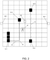
- the system of interconnected, potentially oscillatory cable paths ( 12, 14 ) resides above (or in some cases below) the equipment racks and the nominal location of cables follows a substantially rectilinear grid parallel to the array of network equipment cabinets 10.
- the locations of the wireless transmitter 37, controller 36, charging stations 38, and equipment bays 10 are shown by way of example in this figure.
- the fiber optic cable path 12 with first spatial period and path 14 with second spatial period follow an oscillatory pattern, wherein the spatial period of the oscillation is computed based on the excess cable length to be managed and the preexisting, locally varying density of cables along the tray system.
- the shortest path-length between two network device ports requiring a connection is equal to the nearest available length of fiber cable cartridge 20 that is greater than the shortest path length and that does not cause the local cable density in the tray to exceed the rated limits.
- Figure 3 is a flow diagram of the algorithm used to compute the optimal physical path of each fiber interconnection within the fixed cable tray network.
- the goal of the algorithm is to distribute the excess cable length uniformly within the cable tray system to avoid clustering or bunching of cables at certain locations, which is a common concern when large numbers of cables are manually installed with all the slack bunched in the vicinity of one or both cable endpoints.
- the algorithm further tries to avoid local spots in the cable tray system for which the cable fill factor is approaching 100%.
- the first step in the routing process is to enter the start and stop locations of the cable as required to connect a pair of network devices at step 100 and determine the location of start and stop points on cable tray map at step 102. This may be performed by an operator, engineer, or programmatically by reading in, for example, a spreadsheet with required connections and physical coordinates for each connection.
- the next step 104 is to compute the shortest possible cable length between the two endpoints by following straight-line paths along the rectilinear array of cable trays/tracks. This calculation includes the determination of the density of pre-existing cables within the tray system and the identification of any cable clusters that may be clogging or overfilling the tray system.
- the system checks the inventory of available cable cartridges in different lengths at step 108 and selects the shortest available cable length that is longer than the computed shortest possible cable length. The difference between the two lengths is what determines the period and potentially the amplitude of the oscillatory path.
- the cartridge can be loaded manually or automatically by cassette loader 41.
- the oscillatory path y(x) is described by one or more sinusoidally varying segments characterized mathematically and physically by an amplitude of oscillation a and spatial period of oscillation b .
- the oscillatory path length is computed at step 110, for example, with amplitude of 25 cm while the period of oscillation is decreased from 10 meters to 1 cm. This selection for amplitude translates into a cable tray with an inside width of at least 50 cm.
- the path length calculation in step 110 is typically iterative and based on numerical integration and differentiation of the cable path function y(x) , as shown in Figure 3 .
- the local period of oscillation is calculated by setting the corresponding path-length with oscillations equal to the cable length of the available cable cartridge.
- the next step is to load the selected cable cartridge into the dispensing robot, by manual or automatic means.
- the cable is then deployed in the cable tray system at step 112, wherein the system lays out the cable according to the calculated oscillatory path.
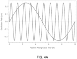
- Figure 4A is an example graph of a sinusoidal oscillatory path segment with substantially constant 25 cm amplitude a and a variable spatial period b , the period being set to produce the desired path-length.
- the sinusoidal path versus a square wave is desirable because it subjects the fiber optic cable to minimal bending stress where it turns around.
- the optimal path is a slight variation of a sinusoid, in which the path consists of rectangular segments with substantially rounded corners, as shown in the dotted line in Figure 4A .
- the radius of rounded corners is selected based on the minimum acceptable bend radius for that particular fiber.
- the minimum acceptable radius (while maintaining low optical insertion loss and low bending stress in glass fiber) varies from >25 mm down to ⁇ 5 mm.
- Figures 4B and 4C illustrate a top view and a cross-sectional view, respectively, of multiple independent cables with different periods of oscillation, laid upon one another within a straight segment of the cable tray.
- Figure 4D illustrates an extended cable tray network 17 with localized high cable density 29, medium cable density 30, and low cable density 31 regions. The local period of oscillation of each cable laid therein varies based upon the local cable density.
- the distribution of pre-existing cable density is entered into the cable calculation process (step 110 ) of flow chart ( Figure 3 ). For example, the cable segment 12 exhibits a short oscillation period within the low-density region 31 and the cable segment 14 exhibits a longer oscillation period within the medium cable density regions 30 to tend to even out the fill factor.
- the cable period of oscillation is very long or infinite (no oscillation), so that a minimal volume of cable is dispensed in this already full region 29.
- fibers 12-1 ... 12-N that fill this tray, each with their own unique oscillation paths.
- subsequent cables laid therein are dispensed with a trajectory that reduces the variation in the cable tray fill factor along its length.
- Figure 5 is a graph illustrating path length as a function of oscillation period of the oscillatory path for a fixed 25-cm oscillation amplitude a and with a programmable spatial period b varying from 10-cm to 100-cm for an individual installed fiber cable path within the cable tray.
- This path length calculation is based on a specific example: a 100-meter long cable tray with 25-cm transverse oscillation amplitude.
- the horizontal axis in Figure 5 is the spatial period of oscillation in cm, and the vertical axis is the path-length in meters of the oscillatory path as a function of the spatial period. It can be seen that the amount of slack cable distributed along the 100-m length is significant.
- an oscillation period of 10-m maintains the path length at only slightly more than 100-m, the straight-line length of the cable tray segment.
- the path length increases to 150-m.
- the path length increases to nearly 500-m. Therefore, this oscillatory approach is very effective at managing and distributing slack cable within the cable tray system.
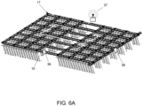
- Figure 6A illustrates a rectilinear cable tray/track system 17 installed above and parallel to aisles of the equipment bays 10 within a data center.
- the charging stations 38 are disposed to charge the robot battery (not shown) in between reconfigurations.
- the robot communication to the server 36 is via a wireless connection, so a wireless signal distribution antenna 37 with sufficient range is required in proximity to the track segments.
- cable tray systems 17 are typically elevated and run above the tops of the equipment racks 10. Technicians must use ladders to access trays and run cables therein, which is a time consuming, labor-intensive process.
- Fiber optic cables within these trays takes several forms, including individual duplex or simplex cables with 0.9-mm, 1.6-mm, 2.0-mm or 3.0-mm outer diameters. Moreover, larger diameter structured cabling with outer diameters ranging from 3-mm to 10-mm and fiber counts of 12 to 96 per jacket may be used up to limits in diameter of fiber bundle that can be dispensed. Cable tray systems can be complex, including two tiers of cable trays at different heights, with each tray being utilized for a different type of cable (e.g. optical fiber vs. copper).
- the cable tray system 17 includes a bottom cable tray section 21 and further incorporates an upper track system 26 integral with a tray cover 18 to support and guide the cable dispensing robot 19.
- the cable dispensing robot 19 accepts a standard patchcord cartridge 20 and then travels down the track system autonomously with the intelligence to optimally dispense/route cable to minimize clustering of the cables within the trays and to automatically manage excess cable lengths.
- Fiber optic cables with protective jackets and KEVLAR strength reinforcement are typically 1.6 to 3.0-mm in diameter. This structure is required to protect the internal optical fiber during manual installation into trays. This manual process involves pulling the cable, which would otherwise damage cables if they did not have protective jackets and KEVLAR strength reinforcement. The added size and mass of the cable is significant and limits the cable density within the cable tray.
- Bend insensitive optical fiber e.g. Corning CLEARCURVE ZBL, single mode and multimode
- the fiber diameter of a tight buffered or loose tube optical fiber is typically only 0.5 to 0.9-mm in diameter. This significantly increases the density achievable within the cable tray system by a factor of ten or more.
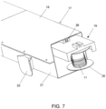
- deployable fiber cassettes in accordance with this invention would include two fibers that are deployed substantially parallel to one another. In the preferred embodiment, this miniature fiber 11 is spooled on the cable cartridges 20 in Figure 7 and is ready for deployment.
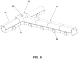
- the cable tray system as illustrated in Figure 8 consists of multiple interlocking cable tray segments typically constructed of injection molded plastic or metal wire mesh tray segments with suitable hardware to suspend from a ceiling or mount to the top of the racks and/or enclosures.
- Cable trays include a bottom section 21 or trough for storage of cables and an upper section 18 forming a top cover. This top cover must have an integral track structure.
- Cable tray sections further include outlet ports 22 from which cables exit the tray and connect to equipment thereunder.
- the cable trays 17 built up of interlocking cable tray segments 26 may intersect at right angles, and at the switch segments 23 an actuator element 24 is provided to turn/redirect the cable dispensing robot 19 along a different substantially straight line path as required.
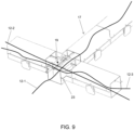
- FIG. 9 illustrates the cable tray system with two cables 12-1 and 12-3 disposed therein. Cables will typically cross over one another at intersection points in the switch segments 23.
- Figure 11 illustrates a reciprocating arm 25 of cable dispensing robot 19 suspended from track segment 26, wherein the arm with feed rollers 27 is used to deploy the cable 11 from the spool 20 to the cable tray (not shown here for clarity) in the shape of the oscillatory path 12 with period b and amplitude a.
- the robot 19 further includes first and second drive motors 35-1, 35-2 that transport the robot 19 down curved track section 33, as shown in Figure 15 . Power is supplied by internal battery 16.
- the reciprocating arm 25 moves to the outlet port 22 and feeds the remaining cable 12 and its connectorized end 32 off of the spool 20, so that the cable's connector 32 drops out of cable tray port 22 and a drop down cable segment 13 of cable 12 has sufficient length to reach the corresponding port 42 of a network device 41 within the rack 10 below.
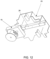
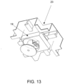
- FIGS 12-14 detail the robot 19 as it travels through an intersection or crossing-point segment 23, in which a switchable track segment 28 allows the dispensing robot 19 to change direction while deploying the cable.
- the cable can then be routed through a 90 or 180-degree angle through the switch section.
- the autonomous cabling system comprises the following elements:
- the robotic dispenser includes the following features in addition to those set forth above:
- the robotic cable dispenser 19 or shuttle carries one or more small diameter fiber optic cables pre-wound on a spool 20.
- a technician selects and installs a pre-loaded spool with correct cable length into the dispenser at a starting point.
- the spool is configured to allow the dispenser to payout cable by rotating the spool in coordination with its travel down the cable tray system 17.
- Both ends of cable on spool may further include a unique label, barcode or RFID identifier in the vicinity of the connector that is automatically entered into the management system at the time of installation.
- the shuttle travels on guide tracks 26 laid out parallel and/or perpendicular to the aisles.
- the shuttle is controlled wirelessly and is battery powered.
- the fiber optic tray system 17 is arranged in a rectangular grid and the trays define the paths over which the cables may be routed. Routing is based on computation of the optimal path based on current fill state of cable tray system so that congestion of the cable tray at any particular location is avoided. Cabling system's software engine residing on management server 36 performs the routing calculation.
- the fiber optic connectors 32 at both ends of each cable 12 include an RFID reader and/or barcode.
- the shuttle includes an RFID reader and/or a camera scanning system to read the barcodes.
- the shuttle pays-out fiber from a spool cartridge 20. The load produced by the fiber optic cable is relatively low and the suspended shuttle can be relatively small, compact and inexpensive.
- this interconnect architecture and system reduces the need for intermediate distribution frames and main distribution frames (IDFs and MDFs, respectively).
- IDFs and MDFs main distribution frames
- Programmable, direct fiber optic cable connections 12, 14 can be made between all equipment bays. This allows for significant space and cost reduction.
- One robot or shuttle 19 can replace all the distribution frames and technicians normally deployed in the data center.
- the optimal path to route each cable 12 along the cable tray grid is selected by a network management controller, based on the three-dimensional locations of cable endpoints and on available lengths of the cable provided in spool form and loaded into the cable dispensing robot 19.
- An algorithm is used by controller to automatically manage and distribute the slack cable within the cable track so that the cable installation is highly organized. For example, the spatial period and amplitude of repeated transverse oscillation pattern of cable is computed by the control system to uniformly distribute slack along the cable tray and reduce excessive bunching and overfilling at certain locations along the tray.
- the system for automated data center cabling installation thus includes the following key elements of the system:
- the cable-laying robot can also remove a specific cable from the cable tray by re-spooling it into the cable-laying robot.
- This cable can potentially be re-used.
- connectors may be removed and the cable may be cut into substantially straight sub-sections, with the cuts located at positions along the cable trays where the cable undergoes a change of direction, say by 90-degrees or 180-degrees. These cable sub-sections can then be removed by re-spooling it into the cable-laying robot.
- a segment of track network 17 may extend into a cable cassette loading/unloading system 41, said loading/unloading system including actuation means to select and present a particular cassette 20 with length of cable 11 to the cable dispensing robot 19 so that further actuation installs a new cassette 20 into robot 19.
- the loading/unloading system 41 may also include actuation means to remove spool of cassette 20 once the cable 11 is fully dispensed.
Landscapes
- Physics & Mathematics (AREA)
- General Physics & Mathematics (AREA)
- Optics & Photonics (AREA)
- Engineering & Computer Science (AREA)
- Architecture (AREA)
- Civil Engineering (AREA)
- Structural Engineering (AREA)
- Manipulator (AREA)
- Electric Cable Arrangement Between Relatively Moving Parts (AREA)
Claims (15)
- Lichtwellenleiterkabel-Installationsrobotersystem zur Installation einer Vielzahl von Lichtwellenleiterkabeln zwischen ersten und zweiten beabstandeten Ausrüstungsgestellen (10) innerhalb einer Einrichtung, das von einer Steuerung (36) gesteuert wird, auf der sich ein Kabelausbringungsalgorithmus befindet, wobei das System Folgendes umfasst:ein Kabelträgersystem (17), das oberhalb und im Wesentlichen fluchtend mit Reihen von Geräteregalen (10) angeordnet ist, wobei das Kabelträgersystem (17) einen unteren Kabelaufnahmeabschnitt (21) mit periodisch beabstandeten Kabelauslassöffnungen (22), ein oberes Schienensystem (26), das mit einer Trägerabdeckung (18) integriert ist, und eine Vielzahl von Schienenweichenabschnitten an Stellen aufweist, an denen sich Schienen des oberen Schienensystems (26) kreuzen; undeinen oder mehrere Kabelausgaberoboter (19), wobei jeder Kabelausgaberoboter zum individuellen Ausgeben eines vorgespulten faseroptischen Kabels entlang eines Weges dient, der durch den Kabelausbringungsalgorithmus bestimmt wird, in dem unteren Abschnitt (21)wobei jeder der Kabelausgaberoboter ein motorisiertes oberes Schieneneingriffselement zum Eingriff in das obere Schienensystem (26) aufweist,ein Antriebselement (35) zum Bewegen des Roboters entlang des oberen Schienensystems,ein hin- und hergehendes Kabelzuführungselement (25, 27) zum Verlegen des vorgespulten faseroptischen Kabels entlang des Wegesein drahtloses Kommunikationselement für die Kommunikation zwischen dem Roboter (19) und der Steuerung (36), undein Leistungselement (16) zur Versorgung des Antriebselements (35), des Kabelzuführungselements (25, 27) und des drahtlosen Kommunikationselements.
- System nach Anspruch 1, wobeider Pfad ein transversaler oszillierender Pfad mit einer programmierbaren räumlichen Periode ist, die durch den Kabelausbringungsalgorithmus bestimmt wird, und wobeider transversale oszillierende Pfad so gewählt ist, dass eine Überlänge des Kabels innerhalb und entlang der Länge des unteren Kabelaufnahmeabschnitts (21) verteilt ist, wobeidie überschüssige Länge des Kabels auf einer Länge des vorgespulten Glasfaserkabels und der minimalen Weglänge zwischen einem Anschluss an dem ersten Geräteträger und einem Anschluss an dem zweiten Geräteträger basiert, um eine überschüssige Kabeldichte an einer bestimmten Stelle entlang der Strecke zu verhindern.
- System nach Anspruch 1, wobei das Kabel ein vorgespultes faseroptisches Patchkabel mit kleinem Außendurchmesser und einer bestimmten Länge umfasst, wobei das Patchkabel faseroptische Verbinder umfasst, die an einem ersten und einem zweiten Ende des Patchkabels angeordnet sind, die in Aufnahmeports an den ersten und zweiten Ausrüstungsgestellen eingesteckt werden;
wobei das drahtlose Kommunikationselement so konfiguriert ist, dass es die Steuerung in die Lage versetzt, geeignete Befehlsanweisungen an den und von dem Kabelausgaberoboter zu senden und zu empfangen. - System nach Anspruch 3, wobei die Patchkabel einen Außendurchmesser von 0,5 mm bis 1 mm haben und an beiden Enden LC-Stecker aufweisen.
- System nach Anspruch 1, wobei die voneinander beabstandeten Ausrüstungsgestelle (10) bis zu 1.000 Meter voneinander entfernt sind.
- System nach Anspruch 1, bei dem die Kabelträger mindestens 25 cm breit und 25 cm hoch sind und sich in Querrichtung mindestens 1 Meter erstrecken, um eine Vielzahl von Gestellen zu erreichen.
- Faseroptisches Kabelinstallationsrobotersystem nach Anspruch 1,wobei das Kabelträgersystem aufgehängte Kabelträgersegmente umfasst, und wobei die Steuerung (36) Folgendes umfassteinen Verbindungsplatzierungsalgorithmus zum Installieren einer zusätzlichen faseroptischen Verbindung zwischen einem Paar von Anschlüssen an verschiedenen Netzwerkvorrichtungen in den Ausrüstungsgestellen (10); wobei die Verbindungen im Wesentlichen innerhalb des Kabelträgersystems aus aufgehängten Kabelträgersegmenten liegen und das Kabelträgersystem mehrere potenzielle Pfade zwischen dem Paar von Anschlüssen aufweist; wobei das System ferner Folgendes umfasstMittel zum Verfolgen und Speichern der Positionen aller bereits existierenden Zwischenverbindungen innerhalb des Kabelträgersystems, um einen Füllungsgrad in jedem Trägersegment zu ermitteln, und wobei die Steuerung so programmiert ist, dass sie einen optimalen Pfad berechnet, um eine zusätzliche Zwischenverbindung zwischen dem Paar von Anschlüssen zu leiten und überschüssige Zwischenverbindungslänge zu verteilen, und ferner eine minimale Länge der Zwischenverbindung berechnet;eine Einrichtung zum Laden der zunächst auf einer Kassette verpackten Zwischenverbindung in den Kabelausgaberoboter, wobei die Zwischenverbindung so ausgewählt wird, dass sie zumindest die Mindestlänge aufweist; undeinen Kabelausgaberoboter, der die Verbindung entlang einer sich hin- und herbewegenden Bahn innerhalb des Kabelträgersystems ausbringt, wobei eine räumliche Periode der Bahn so gewählt ist, dass sie die überschüssige Länge der Verbindung, die die Mindestlänge überschreitet, aufnehmen kann, wodurch die überschüssige Länge der Verbindung entlang der Länge des Kabelträgersystems verteilt wird.
- System nach Anspruch 7, wobei die Zwischenverbindung in dem Kabelträgersystem mit einem im Wesentlichen sinusförmigen Muster verlegt wird, dessen Amplitude und Periode durch einen Algorithmus bestimmt werden, der sich in dem Steuergerät befindet, um die überschüssige Länge der Zwischenverbindung gleichmäßig entlang des Kabelträgersystems zu verteilen.
- System nach Anspruch 8, wobei das Kabelträgersystem so bemessen ist, dass es mehr als 1.000 faseroptische Verbindungen tragen kann.
- System nach Anspruch 9, wobei die Verbindungen einen Durchmesser von 0,5 bis 1,6 mm haben und jede Verbindung aus 1 bis 24 einzelnen optischen Fasern besteht.
- System nach Anspruch 8, bei dem die räumliche Periode 0,5 bis 10 Meter beträgt.
- Kompaktes Kabelverlegungsrobotersystem zur Verwendung in einem Faseroptikkabel-Installationsrobotersystem nach Anspruch 1, wobei das Kabelverlegungsrobotersystem umfasstein motorisiertes Antriebssystem, um den Kabelverlegeroboter entlang eines Oberleitungsschienen- und Kabelträgersystems anzutreiben;ein drahtloses Kommunikationselement;eine austauschbare Glasfaserkabelkassette, die eine vorbestimmte Länge eines Glasfaserkabels enthält, das ein erstes und ein zweites Ende mit Verbindern an beiden Enden aufweist;einen motorisierten Glasfasertrommelhalter, auf dem sich die Glasfaserkabelkassette befindet; undein programmierbares, sich hin- und herbewegendes, motorisiertes Faserausgabesystem zum Verlegen des Kabels innerhalb eines Kabelträgers entlang einer deterministischen, oszillierenden Bahn.
- Roboter nach Anspruch 12, wobei die Kassette für faseroptische Kabel bis zu 100 Meter Kabel aufnehmen kann.
- Roboter nach Anspruch 12, wobei das faseroptische Kabel einen Außendurchmesser von 0,5 bis 1,6 mm hat und jedes Kabel aus 1 bis 24 einzelnen und unabhängigen optischen Fasern bestehen kann.
- Roboter nach Anspruch 12, der ferner ein integriertes RFID- oder Barcode-Lesegerät zum Auslesen eines RFID-Tags enthält, dessen Daten die Kabellänge auf der Kabelkassette enthalten.
Applications Claiming Priority (1)
| Application Number | Priority Date | Filing Date | Title |
|---|---|---|---|
| PCT/US2017/069160 WO2019133021A1 (en) | 2017-12-30 | 2017-12-30 | Automated installation and reconfiguration of fiber optic and copper cables in large scale data centers |
Publications (3)
| Publication Number | Publication Date |
|---|---|
| EP3732520A1 EP3732520A1 (de) | 2020-11-04 |
| EP3732520A4 EP3732520A4 (de) | 2021-12-29 |
| EP3732520B1 true EP3732520B1 (de) | 2024-01-24 |
Family
ID=67068034
Family Applications (1)
| Application Number | Title | Priority Date | Filing Date |
|---|---|---|---|
| EP17936770.1A Active EP3732520B1 (de) | 2017-12-30 | 2017-12-30 | Automatische installation und rekonfiguration von glasfaser- und kupferkabeln in grossraumdatenzentren |
Country Status (3)
| Country | Link |
|---|---|
| US (1) | US11705707B2 (de) |
| EP (1) | EP3732520B1 (de) |
| WO (1) | WO2019133021A1 (de) |
Families Citing this family (19)
| Publication number | Priority date | Publication date | Assignee | Title |
|---|---|---|---|---|
| WO2018071341A2 (en) | 2016-10-10 | 2018-04-19 | Telescent Inc. | System of large scale robotic fiber cross-connects using multi-fiber trunk reservation |
| US11252488B2 (en) | 2017-10-09 | 2022-02-15 | Telescent Inc. | Incrementally scalable, two-tier system of robotic, fiber optic interconnect units enabling any-to-any connectivity |
| EP3688890A4 (de) | 2017-09-30 | 2021-09-01 | Telescent Inc. | Optische monitore mit geringem verlust, anordnungen optischer monitore und schalttafeln optischer monitore |
| US11650598B2 (en) | 2017-12-30 | 2023-05-16 | Telescent Inc. | Automated physical network management system utilizing high resolution RFID, optical scans and mobile robotic actuator |
| EP3732520B1 (de) | 2017-12-30 | 2024-01-24 | Telescent Inc. | Automatische installation und rekonfiguration von glasfaser- und kupferkabeln in grossraumdatenzentren |
| US12462122B2 (en) | 2017-12-30 | 2025-11-04 | Telescent Inc. | Automated physical network management system utilizing high-resolution RFID, optical scans, and mobile robotic actuator |
| WO2019224657A1 (en) | 2018-05-25 | 2019-11-28 | Telescent Inc. | Automated fiber optic interconnection system based on non-repeating braid algorithm, robot, and fixed, identical length optical fibers |
| WO2021044556A1 (ja) * | 2019-09-04 | 2021-03-11 | 日本電信電話株式会社 | ケーブルルート設定方法 |
| WO2021046227A1 (en) | 2019-09-05 | 2021-03-11 | Telescent Inc. | Robotic fiber optic cross-connect systems, sub-systems, devices and methods |
| US11866079B2 (en) * | 2020-02-14 | 2024-01-09 | Georgia Tech Research Corporation | Wire-traversing robot and method of operation |
| US11347955B2 (en) | 2020-03-09 | 2022-05-31 | Panduit Corp. | Cable management system and method |
| US12197997B2 (en) | 2020-03-09 | 2025-01-14 | Panduit Corp. | Cable management system and method |
| CN111716351A (zh) * | 2020-05-08 | 2020-09-29 | 南方电网科学研究院有限责任公司 | 一种导线施工机器人控制系统 |
| CN113945178B (zh) * | 2020-07-15 | 2023-10-20 | 中国电信股份有限公司 | 机房跳纤长度计算方法和系统 |
| CN113595565B (zh) * | 2021-07-29 | 2022-11-29 | 四川省大见通信技术有限公司 | 一种支持远程变频的微分布设备 |
| DE102021132837A1 (de) | 2021-12-13 | 2023-06-15 | Goodville Gmbh | Kabellegesystem zur automatisierten Verlegung von Kabeln in einem Gebäude mit einer Kabellegevorrichtung und Kabellegevorrichtung |
| US12191640B2 (en) * | 2022-03-18 | 2025-01-07 | CyberSecure IPS, LLC | Facilitating installation of cables within datacenters |
| US20240126040A1 (en) * | 2022-10-13 | 2024-04-18 | Corning Research & Development Corporation | Routing tool for installation of fiber optic cables and method of using same |
| CN118139392B (zh) * | 2024-05-08 | 2024-07-23 | 广东欢联电子科技有限公司 | 一种数据中心冷却系统的优化节能控制方法及系统 |
Family Cites Families (38)
| Publication number | Priority date | Publication date | Assignee | Title |
|---|---|---|---|---|
| FR2650922A1 (fr) | 1989-08-08 | 1991-02-15 | Pecot Alain | Entraineurs intermediaires de cable a commande automatique |
| FR2653946B1 (fr) * | 1989-10-31 | 1992-02-14 | Dehe Entreprises A | Procede de deroulage et de mise en place d'un cable a fibres optiques et installation pour la mise en óoeuvre de ce procede. |
| US5551545A (en) * | 1994-03-18 | 1996-09-03 | Gelfman; Stanley | Automatic deployment and retrieval tethering system |
| US6584267B1 (en) * | 2000-06-02 | 2003-06-24 | Panduit Corp. | Cable management system |
| US6603907B2 (en) | 2001-03-16 | 2003-08-05 | Neutron Media, Llc | Communications network and method of installing the same |
| US7331436B1 (en) * | 2003-03-26 | 2008-02-19 | Irobot Corporation | Communications spooler for a mobile robot |
| US7315681B2 (en) | 2004-08-09 | 2008-01-01 | Anthony Kewitsch | Fiber optic rotary coupling and devices |
| WO2006035499A1 (ja) * | 2004-09-29 | 2006-04-06 | Hitachi Chemical Co., Ltd. | 光電気集積回路素子およびそれを用いた伝送装置 |
| US7289197B2 (en) | 2004-12-22 | 2007-10-30 | Anthony Stephen Kewitsch | Transmissive optical detector |
| US7665901B2 (en) | 2006-02-17 | 2010-02-23 | Telescent Inc. | Protective fiber optic union adapters |
| US7460753B2 (en) | 2006-07-06 | 2008-12-02 | Anthony Stephen Kewitsch | Shape-retaining fiber optic cables having limited bend radius |
| US7920764B2 (en) | 2007-05-04 | 2011-04-05 | Anthony Stephen Kewitsch | Electrically traceable and identifiable fiber optic cables and connectors |
| US9110249B2 (en) | 2007-10-02 | 2015-08-18 | Telescent Inc. | In-line fiber optic monitors responsive to optical intensity |
| US8068715B2 (en) * | 2007-10-15 | 2011-11-29 | Telescent Inc. | Scalable and modular automated fiber optic cross-connect systems |
| US8554033B2 (en) | 2008-05-02 | 2013-10-08 | Telescent Inc. | Radio frequency identification overlay network for fiber optic communication systems |
| US8488938B2 (en) | 2008-08-21 | 2013-07-16 | Telescent Inc. | Braided fiber optic cross-connect switches |
| US8559783B2 (en) * | 2009-04-30 | 2013-10-15 | Corning Cable Systems Llc | Mounting assembly for fiber optic equipment |
| CN102460261B (zh) * | 2009-06-19 | 2016-11-09 | 康宁光缆系统有限责任公司 | 高容量光纤连接基础设施装置 |
| US20100329621A1 (en) * | 2009-06-26 | 2010-12-30 | Elli Makrides-Saravanos | Fiber Optic Cable Slack Storage Module |
| US9417418B2 (en) * | 2011-09-12 | 2016-08-16 | Commscope Technologies Llc | Flexible lensed optical interconnect device for signal distribution |
| WO2014097291A1 (en) * | 2012-12-20 | 2014-06-26 | Fiberzone Networks Ltd. | Switching patch cord fibers |
| KR20140133286A (ko) * | 2013-05-10 | 2014-11-19 | 주식회사 로보게이트 | 케이블 트레이용 케이블 가설 로봇시스템 |
| CN103427371B (zh) * | 2013-08-16 | 2016-12-07 | 中冶南方工程技术有限公司 | 一种电缆路径智能寻优方法 |
| KR101516554B1 (ko) | 2013-09-11 | 2015-05-04 | 삼성중공업 주식회사 | 케이블 포설 시스템 |
| US9703060B2 (en) | 2013-10-04 | 2017-07-11 | Telescent Inc. | Ultra-compact, software-defined fiber optic patch-panels |
| KR20150087043A (ko) * | 2014-01-21 | 2015-07-29 | 대우조선해양 주식회사 | 케이블 꼬임 검출장치 및 그 방법 |
| CN203786352U (zh) * | 2014-01-27 | 2014-08-20 | 西安海驰通信科技有限公司 | Lc型细径光纤跳线 |
| US9597801B2 (en) * | 2014-10-21 | 2017-03-21 | Centurylink Intellectual Property Llc | Automated data center |
| US9946832B2 (en) * | 2014-11-13 | 2018-04-17 | Lenovo Enterprise Solutions (Singapore) Pte. Ltd. | Optimized placement design of network and infrastructure components |
| US10345526B2 (en) * | 2014-12-14 | 2019-07-09 | Telescent Inc. | High reliability robotic cross-connect systems |
| CN105590002B (zh) * | 2015-12-31 | 2019-01-25 | 北京理工大学 | 一种分支线缆自动布局方法及装置 |
| US11252488B2 (en) | 2017-10-09 | 2022-02-15 | Telescent Inc. | Incrementally scalable, two-tier system of robotic, fiber optic interconnect units enabling any-to-any connectivity |
| US11199662B2 (en) | 2016-10-10 | 2021-12-14 | Telescent Inc. | Ultra-scalable, multi-tiered, robotic fiber optic cross-connect utilizing trunk line physical aggregation |
| WO2018071341A2 (en) | 2016-10-10 | 2018-04-19 | Telescent Inc. | System of large scale robotic fiber cross-connects using multi-fiber trunk reservation |
| EP3688890A4 (de) | 2017-09-30 | 2021-09-01 | Telescent Inc. | Optische monitore mit geringem verlust, anordnungen optischer monitore und schalttafeln optischer monitore |
| EP3732517A4 (de) | 2017-12-30 | 2021-11-17 | Telescent Inc. | Automatisiertes physikalisches netzwerkverwaltungssystem mit hochauflösender rfid- und optischer abtastung zur räumlichen lokalisierung von rfid-etiketten |
| EP3732520B1 (de) | 2017-12-30 | 2024-01-24 | Telescent Inc. | Automatische installation und rekonfiguration von glasfaser- und kupferkabeln in grossraumdatenzentren |
| WO2021046227A1 (en) | 2019-09-05 | 2021-03-11 | Telescent Inc. | Robotic fiber optic cross-connect systems, sub-systems, devices and methods |
-
2017
- 2017-12-30 EP EP17936770.1A patent/EP3732520B1/de active Active
- 2017-12-30 WO PCT/US2017/069160 patent/WO2019133021A1/en not_active Ceased
- 2017-12-30 US US16/958,704 patent/US11705707B2/en active Active
Also Published As
| Publication number | Publication date |
|---|---|
| EP3732520A1 (de) | 2020-11-04 |
| US20200358277A1 (en) | 2020-11-12 |
| EP3732520A4 (de) | 2021-12-29 |
| WO2019133021A1 (en) | 2019-07-04 |
| US11705707B2 (en) | 2023-07-18 |
Similar Documents
| Publication | Publication Date | Title |
|---|---|---|
| EP3732520B1 (de) | Automatische installation und rekonfiguration von glasfaser- und kupferkabeln in grossraumdatenzentren | |
| RU2670183C2 (ru) | Распределительное устройство с возможностью добавления разветвителей | |
| KR100399659B1 (ko) | 광섬유분배시스템 | |
| EP3230780B1 (de) | Verwaltungsmodul für faseroptische kabelüberlängen | |
| US8488938B2 (en) | Braided fiber optic cross-connect switches | |
| US6819857B2 (en) | Rotating vertical fiber tray and methods | |
| CA1250135A (en) | Method and apparatus for handling and storing cabled spliced ends of fiber optics | |
| US6721482B1 (en) | Telecommunications fiber optic infrastructure | |
| US8953920B2 (en) | Semi-automated optical fiber distribution system | |
| US20190072736A1 (en) | High density distribution frame with an integrated splicing compartment | |
| KR101201989B1 (ko) | 광섬유 커플링 장치 및 방법 | |
| US12284780B2 (en) | Managing cables in fiber installation | |
| WO2002021186A1 (en) | High density fiber optic cable distribution frame system | |
| EP2033033B1 (de) | Kabelschleifeneinrichtung für optische systeme | |
| CN102089692A (zh) | 带储存卷筒和组织器的光纤分配模块 | |
| US10481358B2 (en) | Termination unit | |
| RU181686U1 (ru) | Разветвитель | |
| WO2002021181A1 (en) | Fiber optic cable bend radius management system | |
| US9904028B2 (en) | Ultra-high density splice systems | |
| EP2538255A1 (de) | Kabelkopplungsvorrichtung mit Überlängenverstauung für Überbrückungskabel | |
| US7200315B2 (en) | Dynamic fiber slack management for telecom racks | |
| US8443989B2 (en) | Media rack configuration | |
| WO1999047960A1 (en) | Optical fibre overlength storage | |
| US20250244550A1 (en) | Splice linear inline drop enclosure | |
| JP2005077689A (ja) | 光コードの余長処理構造 |
Legal Events
| Date | Code | Title | Description |
|---|---|---|---|
| STAA | Information on the status of an ep patent application or granted ep patent |
Free format text: STATUS: THE INTERNATIONAL PUBLICATION HAS BEEN MADE |
|
| PUAI | Public reference made under article 153(3) epc to a published international application that has entered the european phase |
Free format text: ORIGINAL CODE: 0009012 |
|
| STAA | Information on the status of an ep patent application or granted ep patent |
Free format text: STATUS: REQUEST FOR EXAMINATION WAS MADE |
|
| 17P | Request for examination filed |
Effective date: 20200730 |
|
| AK | Designated contracting states |
Kind code of ref document: A1 Designated state(s): AL AT BE BG CH CY CZ DE DK EE ES FI FR GB GR HR HU IE IS IT LI LT LU LV MC MK MT NL NO PL PT RO RS SE SI SK SM TR |
|
| AX | Request for extension of the european patent |
Extension state: BA ME |
|
| DAV | Request for validation of the european patent (deleted) | ||
| DAX | Request for extension of the european patent (deleted) | ||
| RIC1 | Information provided on ipc code assigned before grant |
Ipc: B25J 5/02 20060101ALI20210817BHEP Ipc: H02G 1/06 20060101ALI20210817BHEP Ipc: G02B 6/48 20060101ALI20210817BHEP Ipc: G02B 6/46 20060101AFI20210817BHEP |
|
| A4 | Supplementary search report drawn up and despatched |
Effective date: 20211125 |
|
| RIC1 | Information provided on ipc code assigned before grant |
Ipc: B25J 5/02 20060101ALI20211119BHEP Ipc: H02G 1/06 20060101ALI20211119BHEP Ipc: G02B 6/48 20060101ALI20211119BHEP Ipc: G02B 6/46 20060101AFI20211119BHEP |
|
| STAA | Information on the status of an ep patent application or granted ep patent |
Free format text: STATUS: EXAMINATION IS IN PROGRESS |
|
| 17Q | First examination report despatched |
Effective date: 20230526 |
|
| GRAP | Despatch of communication of intention to grant a patent |
Free format text: ORIGINAL CODE: EPIDOSNIGR1 |
|
| STAA | Information on the status of an ep patent application or granted ep patent |
Free format text: STATUS: GRANT OF PATENT IS INTENDED |
|
| INTG | Intention to grant announced |
Effective date: 20230828 |
|
| GRAS | Grant fee paid |
Free format text: ORIGINAL CODE: EPIDOSNIGR3 |
|
| GRAA | (expected) grant |
Free format text: ORIGINAL CODE: 0009210 |
|
| STAA | Information on the status of an ep patent application or granted ep patent |
Free format text: STATUS: THE PATENT HAS BEEN GRANTED |
|
| AK | Designated contracting states |
Kind code of ref document: B1 Designated state(s): AL AT BE BG CH CY CZ DE DK EE ES FI FR GB GR HR HU IE IS IT LI LT LU LV MC MK MT NL NO PL PT RO RS SE SI SK SM TR |
|
| REG | Reference to a national code |
Ref country code: GB Ref legal event code: FG4D |
|
| REG | Reference to a national code |
Ref country code: CH Ref legal event code: EP |
|
| REG | Reference to a national code |
Ref country code: DE Ref legal event code: R096 Ref document number: 602017078829 Country of ref document: DE |
|
| REG | Reference to a national code |
Ref country code: IE Ref legal event code: FG4D |
|
| REG | Reference to a national code |
Ref country code: LT Ref legal event code: MG9D |
|
| REG | Reference to a national code |
Ref country code: NL Ref legal event code: MP Effective date: 20240124 |
|
| PG25 | Lapsed in a contracting state [announced via postgrant information from national office to epo] |
Ref country code: NL Free format text: LAPSE BECAUSE OF FAILURE TO SUBMIT A TRANSLATION OF THE DESCRIPTION OR TO PAY THE FEE WITHIN THE PRESCRIBED TIME-LIMIT Effective date: 20240124 |
|
| PG25 | Lapsed in a contracting state [announced via postgrant information from national office to epo] |
Ref country code: NL Free format text: LAPSE BECAUSE OF FAILURE TO SUBMIT A TRANSLATION OF THE DESCRIPTION OR TO PAY THE FEE WITHIN THE PRESCRIBED TIME-LIMIT Effective date: 20240124 |
|
| PG25 | Lapsed in a contracting state [announced via postgrant information from national office to epo] |
Ref country code: IS Free format text: LAPSE BECAUSE OF FAILURE TO SUBMIT A TRANSLATION OF THE DESCRIPTION OR TO PAY THE FEE WITHIN THE PRESCRIBED TIME-LIMIT Effective date: 20240524 |
|
| PG25 | Lapsed in a contracting state [announced via postgrant information from national office to epo] |
Ref country code: LT Free format text: LAPSE BECAUSE OF FAILURE TO SUBMIT A TRANSLATION OF THE DESCRIPTION OR TO PAY THE FEE WITHIN THE PRESCRIBED TIME-LIMIT Effective date: 20240124 |
|
| PG25 | Lapsed in a contracting state [announced via postgrant information from national office to epo] |
Ref country code: GR Free format text: LAPSE BECAUSE OF FAILURE TO SUBMIT A TRANSLATION OF THE DESCRIPTION OR TO PAY THE FEE WITHIN THE PRESCRIBED TIME-LIMIT Effective date: 20240425 |
|
| REG | Reference to a national code |
Ref country code: AT Ref legal event code: MK05 Ref document number: 1652613 Country of ref document: AT Kind code of ref document: T Effective date: 20240124 |
|
| PG25 | Lapsed in a contracting state [announced via postgrant information from national office to epo] |
Ref country code: HR Free format text: LAPSE BECAUSE OF FAILURE TO SUBMIT A TRANSLATION OF THE DESCRIPTION OR TO PAY THE FEE WITHIN THE PRESCRIBED TIME-LIMIT Effective date: 20240124 Ref country code: RS Free format text: LAPSE BECAUSE OF FAILURE TO SUBMIT A TRANSLATION OF THE DESCRIPTION OR TO PAY THE FEE WITHIN THE PRESCRIBED TIME-LIMIT Effective date: 20240424 |
|
| PG25 | Lapsed in a contracting state [announced via postgrant information from national office to epo] |
Ref country code: ES Free format text: LAPSE BECAUSE OF FAILURE TO SUBMIT A TRANSLATION OF THE DESCRIPTION OR TO PAY THE FEE WITHIN THE PRESCRIBED TIME-LIMIT Effective date: 20240124 |
|
| PG25 | Lapsed in a contracting state [announced via postgrant information from national office to epo] |
Ref country code: AT Free format text: LAPSE BECAUSE OF FAILURE TO SUBMIT A TRANSLATION OF THE DESCRIPTION OR TO PAY THE FEE WITHIN THE PRESCRIBED TIME-LIMIT Effective date: 20240124 |
|
| PG25 | Lapsed in a contracting state [announced via postgrant information from national office to epo] |
Ref country code: RS Free format text: LAPSE BECAUSE OF FAILURE TO SUBMIT A TRANSLATION OF THE DESCRIPTION OR TO PAY THE FEE WITHIN THE PRESCRIBED TIME-LIMIT Effective date: 20240424 Ref country code: NO Free format text: LAPSE BECAUSE OF FAILURE TO SUBMIT A TRANSLATION OF THE DESCRIPTION OR TO PAY THE FEE WITHIN THE PRESCRIBED TIME-LIMIT Effective date: 20240424 Ref country code: LT Free format text: LAPSE BECAUSE OF FAILURE TO SUBMIT A TRANSLATION OF THE DESCRIPTION OR TO PAY THE FEE WITHIN THE PRESCRIBED TIME-LIMIT Effective date: 20240124 Ref country code: IS Free format text: LAPSE BECAUSE OF FAILURE TO SUBMIT A TRANSLATION OF THE DESCRIPTION OR TO PAY THE FEE WITHIN THE PRESCRIBED TIME-LIMIT Effective date: 20240524 Ref country code: HR Free format text: LAPSE BECAUSE OF FAILURE TO SUBMIT A TRANSLATION OF THE DESCRIPTION OR TO PAY THE FEE WITHIN THE PRESCRIBED TIME-LIMIT Effective date: 20240124 Ref country code: GR Free format text: LAPSE BECAUSE OF FAILURE TO SUBMIT A TRANSLATION OF THE DESCRIPTION OR TO PAY THE FEE WITHIN THE PRESCRIBED TIME-LIMIT Effective date: 20240425 Ref country code: FI Free format text: LAPSE BECAUSE OF FAILURE TO SUBMIT A TRANSLATION OF THE DESCRIPTION OR TO PAY THE FEE WITHIN THE PRESCRIBED TIME-LIMIT Effective date: 20240124 Ref country code: ES Free format text: LAPSE BECAUSE OF FAILURE TO SUBMIT A TRANSLATION OF THE DESCRIPTION OR TO PAY THE FEE WITHIN THE PRESCRIBED TIME-LIMIT Effective date: 20240124 Ref country code: BG Free format text: LAPSE BECAUSE OF FAILURE TO SUBMIT A TRANSLATION OF THE DESCRIPTION OR TO PAY THE FEE WITHIN THE PRESCRIBED TIME-LIMIT Effective date: 20240124 Ref country code: AT Free format text: LAPSE BECAUSE OF FAILURE TO SUBMIT A TRANSLATION OF THE DESCRIPTION OR TO PAY THE FEE WITHIN THE PRESCRIBED TIME-LIMIT Effective date: 20240124 |
|
| PG25 | Lapsed in a contracting state [announced via postgrant information from national office to epo] |
Ref country code: PL Free format text: LAPSE BECAUSE OF FAILURE TO SUBMIT A TRANSLATION OF THE DESCRIPTION OR TO PAY THE FEE WITHIN THE PRESCRIBED TIME-LIMIT Effective date: 20240124 Ref country code: PT Free format text: LAPSE BECAUSE OF FAILURE TO SUBMIT A TRANSLATION OF THE DESCRIPTION OR TO PAY THE FEE WITHIN THE PRESCRIBED TIME-LIMIT Effective date: 20240524 |
|
| PG25 | Lapsed in a contracting state [announced via postgrant information from national office to epo] |
Ref country code: SE Free format text: LAPSE BECAUSE OF FAILURE TO SUBMIT A TRANSLATION OF THE DESCRIPTION OR TO PAY THE FEE WITHIN THE PRESCRIBED TIME-LIMIT Effective date: 20240124 Ref country code: PT Free format text: LAPSE BECAUSE OF FAILURE TO SUBMIT A TRANSLATION OF THE DESCRIPTION OR TO PAY THE FEE WITHIN THE PRESCRIBED TIME-LIMIT Effective date: 20240524 Ref country code: PL Free format text: LAPSE BECAUSE OF FAILURE TO SUBMIT A TRANSLATION OF THE DESCRIPTION OR TO PAY THE FEE WITHIN THE PRESCRIBED TIME-LIMIT Effective date: 20240124 Ref country code: LV Free format text: LAPSE BECAUSE OF FAILURE TO SUBMIT A TRANSLATION OF THE DESCRIPTION OR TO PAY THE FEE WITHIN THE PRESCRIBED TIME-LIMIT Effective date: 20240124 |
|
| PG25 | Lapsed in a contracting state [announced via postgrant information from national office to epo] |
Ref country code: DK Free format text: LAPSE BECAUSE OF FAILURE TO SUBMIT A TRANSLATION OF THE DESCRIPTION OR TO PAY THE FEE WITHIN THE PRESCRIBED TIME-LIMIT Effective date: 20240124 |
|
| PG25 | Lapsed in a contracting state [announced via postgrant information from national office to epo] |
Ref country code: SM Free format text: LAPSE BECAUSE OF FAILURE TO SUBMIT A TRANSLATION OF THE DESCRIPTION OR TO PAY THE FEE WITHIN THE PRESCRIBED TIME-LIMIT Effective date: 20240124 |
|
| PG25 | Lapsed in a contracting state [announced via postgrant information from national office to epo] |
Ref country code: CZ Free format text: LAPSE BECAUSE OF FAILURE TO SUBMIT A TRANSLATION OF THE DESCRIPTION OR TO PAY THE FEE WITHIN THE PRESCRIBED TIME-LIMIT Effective date: 20240124 Ref country code: EE Free format text: LAPSE BECAUSE OF FAILURE TO SUBMIT A TRANSLATION OF THE DESCRIPTION OR TO PAY THE FEE WITHIN THE PRESCRIBED TIME-LIMIT Effective date: 20240124 |
|
| REG | Reference to a national code |
Ref country code: DE Ref legal event code: R097 Ref document number: 602017078829 Country of ref document: DE |
|
| PG25 | Lapsed in a contracting state [announced via postgrant information from national office to epo] |
Ref country code: SK Free format text: LAPSE BECAUSE OF FAILURE TO SUBMIT A TRANSLATION OF THE DESCRIPTION OR TO PAY THE FEE WITHIN THE PRESCRIBED TIME-LIMIT Effective date: 20240124 |
|
| PG25 | Lapsed in a contracting state [announced via postgrant information from national office to epo] |
Ref country code: SM Free format text: LAPSE BECAUSE OF FAILURE TO SUBMIT A TRANSLATION OF THE DESCRIPTION OR TO PAY THE FEE WITHIN THE PRESCRIBED TIME-LIMIT Effective date: 20240124 Ref country code: SK Free format text: LAPSE BECAUSE OF FAILURE TO SUBMIT A TRANSLATION OF THE DESCRIPTION OR TO PAY THE FEE WITHIN THE PRESCRIBED TIME-LIMIT Effective date: 20240124 Ref country code: RO Free format text: LAPSE BECAUSE OF FAILURE TO SUBMIT A TRANSLATION OF THE DESCRIPTION OR TO PAY THE FEE WITHIN THE PRESCRIBED TIME-LIMIT Effective date: 20240124 Ref country code: EE Free format text: LAPSE BECAUSE OF FAILURE TO SUBMIT A TRANSLATION OF THE DESCRIPTION OR TO PAY THE FEE WITHIN THE PRESCRIBED TIME-LIMIT Effective date: 20240124 Ref country code: DK Free format text: LAPSE BECAUSE OF FAILURE TO SUBMIT A TRANSLATION OF THE DESCRIPTION OR TO PAY THE FEE WITHIN THE PRESCRIBED TIME-LIMIT Effective date: 20240124 Ref country code: CZ Free format text: LAPSE BECAUSE OF FAILURE TO SUBMIT A TRANSLATION OF THE DESCRIPTION OR TO PAY THE FEE WITHIN THE PRESCRIBED TIME-LIMIT Effective date: 20240124 |
|
| PLBE | No opposition filed within time limit |
Free format text: ORIGINAL CODE: 0009261 |
|
| STAA | Information on the status of an ep patent application or granted ep patent |
Free format text: STATUS: NO OPPOSITION FILED WITHIN TIME LIMIT |
|
| PG25 | Lapsed in a contracting state [announced via postgrant information from national office to epo] |
Ref country code: IT Free format text: LAPSE BECAUSE OF FAILURE TO SUBMIT A TRANSLATION OF THE DESCRIPTION OR TO PAY THE FEE WITHIN THE PRESCRIBED TIME-LIMIT Effective date: 20240124 |
|
| PG25 | Lapsed in a contracting state [announced via postgrant information from national office to epo] |
Ref country code: IT Free format text: LAPSE BECAUSE OF FAILURE TO SUBMIT A TRANSLATION OF THE DESCRIPTION OR TO PAY THE FEE WITHIN THE PRESCRIBED TIME-LIMIT Effective date: 20240124 |
|
| 26N | No opposition filed |
Effective date: 20241025 |
|
| PG25 | Lapsed in a contracting state [announced via postgrant information from national office to epo] |
Ref country code: SI Free format text: LAPSE BECAUSE OF FAILURE TO SUBMIT A TRANSLATION OF THE DESCRIPTION OR TO PAY THE FEE WITHIN THE PRESCRIBED TIME-LIMIT Effective date: 20240124 |
|
| PG25 | Lapsed in a contracting state [announced via postgrant information from national office to epo] |
Ref country code: MC Free format text: LAPSE BECAUSE OF FAILURE TO SUBMIT A TRANSLATION OF THE DESCRIPTION OR TO PAY THE FEE WITHIN THE PRESCRIBED TIME-LIMIT Effective date: 20240124 |
|
| REG | Reference to a national code |
Ref country code: CH Ref legal event code: PL |
|
| PG25 | Lapsed in a contracting state [announced via postgrant information from national office to epo] |
Ref country code: LU Free format text: LAPSE BECAUSE OF NON-PAYMENT OF DUE FEES Effective date: 20241230 |
|
| REG | Reference to a national code |
Ref country code: BE Ref legal event code: MM Effective date: 20241231 |
|
| PG25 | Lapsed in a contracting state [announced via postgrant information from national office to epo] |
Ref country code: BE Free format text: LAPSE BECAUSE OF NON-PAYMENT OF DUE FEES Effective date: 20241231 |
|
| PG25 | Lapsed in a contracting state [announced via postgrant information from national office to epo] |
Ref country code: CH Free format text: LAPSE BECAUSE OF NON-PAYMENT OF DUE FEES Effective date: 20241231 |
|
| PG25 | Lapsed in a contracting state [announced via postgrant information from national office to epo] |
Ref country code: IE Free format text: LAPSE BECAUSE OF NON-PAYMENT OF DUE FEES Effective date: 20241230 |
|
| PGFP | Annual fee paid to national office [announced via postgrant information from national office to epo] |
Ref country code: FR Payment date: 20251230 Year of fee payment: 9 |
|
| PGFP | Annual fee paid to national office [announced via postgrant information from national office to epo] |
Ref country code: GB Payment date: 20260122 Year of fee payment: 9 |
|
| PGFP | Annual fee paid to national office [announced via postgrant information from national office to epo] |
Ref country code: DE Payment date: 20251223 Year of fee payment: 9 |