EP3733022A1 - Schwenktürsystem und gefriervorrichtung mit einem schwenktürsystem - Google Patents
Schwenktürsystem und gefriervorrichtung mit einem schwenktürsystem Download PDFInfo
- Publication number
- EP3733022A1 EP3733022A1 EP19172074.7A EP19172074A EP3733022A1 EP 3733022 A1 EP3733022 A1 EP 3733022A1 EP 19172074 A EP19172074 A EP 19172074A EP 3733022 A1 EP3733022 A1 EP 3733022A1
- Authority
- EP
- European Patent Office
- Prior art keywords
- swing door
- swing
- doors
- adjacent
- door system
- Prior art date
- Legal status (The legal status is an assumption and is not a legal conclusion. Google has not performed a legal analysis and makes no representation as to the accuracy of the status listed.)
- Pending
Links
Images




Classifications
-
- A—HUMAN NECESSITIES
- A47—FURNITURE; DOMESTIC ARTICLES OR APPLIANCES; COFFEE MILLS; SPICE MILLS; SUCTION CLEANERS IN GENERAL
- A47F—SPECIAL FURNITURE, FITTINGS, OR ACCESSORIES FOR SHOPS, STOREHOUSES, BARS, RESTAURANTS OR THE LIKE; PAYING COUNTERS
- A47F3/00—Show cases or show cabinets
- A47F3/04—Show cases or show cabinets air-conditioned, refrigerated
- A47F3/0404—Cases or cabinets of the closed type
- A47F3/0426—Details
- A47F3/0434—Glass or transparent panels
-
- E—FIXED CONSTRUCTIONS
- E05—LOCKS; KEYS; WINDOW OR DOOR FITTINGS; SAFES
- E05D—HINGES OR SUSPENSION DEVICES FOR DOORS, WINDOWS OR WINGS
- E05D15/00—Suspension arrangements for wings
- E05D15/48—Suspension arrangements for wings allowing alternative movements
- E05D15/50—Suspension arrangements for wings allowing alternative movements for opening at either of two opposite edges
-
- E—FIXED CONSTRUCTIONS
- E05—LOCKS; KEYS; WINDOW OR DOOR FITTINGS; SAFES
- E05Y—INDEXING SCHEME ASSOCIATED WITH SUBCLASSES E05D AND E05F, RELATING TO CONSTRUCTION ELEMENTS, ELECTRIC CONTROL, POWER SUPPLY, POWER SIGNAL OR TRANSMISSION, USER INTERFACES, MOUNTING OR COUPLING, DETAILS, ACCESSORIES, AUXILIARY OPERATIONS NOT OTHERWISE PROVIDED FOR, APPLICATION THEREOF
- E05Y2900/00—Application of doors, windows, wings or fittings thereof
- E05Y2900/20—Application of doors, windows, wings or fittings thereof for furniture, e.g. cabinets
Definitions
- the present invention relates to a swing door system, preferably for use with a freezer device, comprising at least two adjacent swing doors, each door having a transparent region.
- the present invention further relates to a freezer device, comprising a swing door system.
- the present invention further relates to a swing door arrangement comprising a swing door system.
- freezer devices can be found in super markets, convenience stores or the like to provide frozen products for customers, usually being presented on shelves inside the freezer device.
- Such freezer devices usually comprise a cabinet and a plurality of swing doors, which can be opened in horizontal direction by a customer, i.e. rotating the swing doors around a vertical axis.
- the swing doors further have circumferential sealings providing a sealing function between the inner of the freezer device and its outside.
- the sealings attached to the swing doors can comprise magnets to provide a magnetic force-locking connection with mullions and horizontal profiles of the freezer device. This avoids leakage of ambient warm air from the outside of the freezer device into the inside and therefore avoids unnecessary energy consumption for cooling as well as icing and condensation inside the freezer device.
- the swing doors usually comprise large glass panes so that a customer can view the products from outside without having to open the swing doors.
- Embodiments of the invention therefore address the problems of providing an enhanced comfort for customers when accessing a freezer device while providing a sufficient sealing function between the inside and outside of a freezer device together with a sufficient mechanical robustness, flexibility in terms of applicability and implementation and a high visibility of goods from outside the freezer device.
- the present invention provides a swing door system, preferably for use with a freezer device, comprising at least two adjacent swing doors, each swing door having a transparent region, wherein at least one of said two adjacent swing doors comprises a sealing and wherein said at least two adjacent swing doors are arranged such that in a closed position said at least one sealing provides an essentially hermetic sealing function between said two adjacent swing doors.
- the present invention provides a freezer device comprising a swing door system according to one of the claims 1-21 being arranged in a cabinet, such that the opening direction of the swing door system is horizontal and wherein said cabinet is mullion-free.
- the present invention provides a swing door arrangement comprising a swing door system of the claims 1-21 and an at least partially circumferential outer frame for said swing door system wherein said outer frame has horizontal frame elements providing support for the rotating axis of said swing door system.
- freezer device refers in particular in the claims, preferably in the description to a device in which the temperature of the foodstuffs is typically kept between -12°C and -30 °C on normal conditions of use. Normal conditions are defined as operating conditions which exist when the cabinet, including all permanently located accessories, has been set up and situated in accordance with the recommendations of the manufacturer and is in service. Typical examples for such foodstuffs are the products which are stored according to EN23953, part 2 (September 2012) in the temperature classes L1, L2 and L3.
- mullion refers in particular in the claims, preferably in the description to a vertical profile of the outer frame of a freezer device where two doors are arranged adjacent to each other in a cabinet and wherein the mullion is not a vertical side profile of the outer frame, but an "inner" vertical profile in particular arranged in the area of both adjacent doors.
- transparent refers in particular in the claims, preferably in the description to a region, area or the like with which the view on the goods, products or the like inside the freezer device is not obstructed or blocked by one or more opaque elements of the freezer device, for example by spacers, profiles, gaskets, a mullion or by the swing doors.
- non-transparent refers in particular in the claims, preferably in the description to a region, area or the like with which the view on the goods, products or the like inside the freezer device is obstructed or blocked by one or more opaque elements of the freezer device, for example by spacers, profiles, gaskets, a mullion or by the swing doors.
- translucent refers in particular in the claims, preferably in the description to a region, area or the like with which the view on goods, products or the like inside the freezer device is not obstructed or blocked but being diffuse, for instance the dimensions of a product can be seen, but not any labeling of the product, at least not clearly.
- width refers in particular in the claims, preferably in the description, to a length measured in the plane in which the swing doors are arranged when the swing doors are in a closed position.
- depth refers in particular in the claims, preferably in the description, to a length measured in the plane being perpendicular to the plane in which the swing doors are arranged when the swing doors are in the closed position.
- vertical refers in particular in the claims, preferably in the description, to the direction aligned with the direction of the force of gravity, up or down, as materialized with a plumb line.
- a horizontal profile is a profile of the device extending in the horizontal direction, in other words parallel to the surface of the earth.
- essentially hermetic with regard to the term “sealing function” refers in particular in the claims, preferably in the description, to at least one of humidity tightness, moisture vapor tightness and/or fluid tightness, in particular excluding the passage of air and/or of splash-water or the like for common situations in supermarkets or the like.
- the term “essentially hermetic” refers here to a lower level of tightness than the physical definition of "hermetic”.
- Conventional cooler systems are typically not essentially hermetic between adjacent swing doors without mullion. In other words, conventional cooler systems do not provide a sealing function between adjacent swing doors directly.
- sealings may have sealings, but in many cases no circumferential sealings, or no continuous, uninterrupted, circumferential contact between the sealings and/or the sealing surface. Since the working temperature of cooler systems is much higher than the working temperature of freezer systems, no icing problems occur due to humidity of the incoming air.
- One of the advantages is, that the swing doors seal against each other and therefore the mullions can be omitted.
- a further advantage is, that - since a mullion is not necessary - the angled view or the view directly in front of the freezer device on the products is not blocked and therefore the comfort for customers is increased.
- An even further advantage is, that a cost-effective implementation can be provided.
- said at least one sealing is at least translucent, preferably at least partially transparent. This further enhances the view for customers on the products, since the customer's view is not blocked by a non-transparent sealing. A further advantage is that an overall appealing impression for customers is provided.
- each of said at least two adjacent swing doors comprises a sealing for providing said sealing function. This enhances the sealing function and thus energy is saved when using the swing doors in a cooler or freezer device.
- said two adjacent sealings have the same shape.
- the term "same shape” is to be understood in the most general sense or meaning and shall in particular include all shapes which can be transferred into one another, e.g. by rotation or mirroring. This enables manufacturing of the swing door system in a cost-effective way.
- one of said two adjacent sealings is adapted to provide at least partially a form-locking connection. This enables providing for instance a stop by one of the swing doors for the adjacent swing door. Thus, mechanical stability in a closed position as well as an enhanced sealing in a closed position of the swing doors is provided.
- said at least one sealing has at least partially circular shape. This enhances the flexibility in terms of arranging adjacent doors respectively their opening direction: due to the circular shape of the sealing a swing door can either open in the same or in an opposite opening angle with regard to the adjacent swing door.
- said form-locking connection is provided by a partial convex form of one of said sealings and a corresponding concave form of said other one of said sealings. This enables in a simple way to provide a partial form-locking connection.
- the sealing surface provided by said at least one sealing is inclined with an angle to the opening direction of the swing doors from said closed position said angle being smaller than 90°, preferably smaller than 60°, in particular smaller than 30°, preferably 0°. This enables to provide a larger sealing surface thus enhancing the sealing function. Further advantages are that a sufficient sealing function and an easy opening of the swing doors and a larger transparent product display area is provided.
- said at least one sealing has an essentially triangular shape. This enables a reliable attachment to the swing door with two surfaces of the triangular shape wherein the non-attached third surface provides the sealing surface.
- the term "essentially triangular” shall include in particular triangular, triangular with rounded corners, multiple edge corners or the like.
- said two adjacent swing doors are arranged such that a partial overlap, preferably in a formed common plane, in said closed position of said two adjacent swing doors is provided based on the view parallel to the opening direction.
- a partial overlap enables a further enhancement of the sealing function between the two adjacent swing doors.
- At least one of said two adjacent swing doors comprise an angled S-shaped profile at least on a surface of said swing door directed to the other adjacent swing door. This enables in a simple way a partial overlap of two adjacent swing doors while providing enhanced protection of the corresponding surfaces by the profile.
- a smooth S-shaped profile, a quarter circular profile, or the like can be used.
- said angle S-shaped profile is at least translucent, preferably at least partially transparent. This further enhances the angled view of customers on products behind the swing doors since there is no blocking of the view by non-transparent profiles.
- said partial overlap is provided by an extending pane of one swing door in the direction to the other adjacent swing door and vice versa. This provides in a simple way a partial overlap and enables an enhanced sealing function.
- one of said two adjacent swing doors is formed such to provide a stop for the other adjacent swing door. This enhances the handling of the swing doors for customers on the one hand and on the other hand a reliable closure as well as an enhanced sealing function is enabled.
- At least one of said two swing doors comprises a gas-filled insulating glass unit or a vacuum glass unit, said gas-filled insulating glass unit or said vacuum glass unit comprises at least two glass panes being spaced apart from each other by one or more spacer elements.
- Said gas-filled insulating unit may comprise air and/or a one or more noble gases.
- said spacer elements are at least translucent, preferably at partially transparent. This further enhances the angled view of customers on products behind the swing doors since there is no blocking of the view by non-transparent spacers.
- said two sealings are provided with magnetic means, preferably permanent magnets, to provide a magnetic force between said two sealings.
- magnetic means preferably permanent magnets
- the sealing function may be further enhanced by arranging in a step-by-step manner permanent magnets.
- at least one of said sealings comprises a horizontal section and/or an additional sealing arranged preferably along the horizontal interface between a swing door element or an area and an outer horizontal frame profile or a cabinet structure providing a sealing of the corresponding door with the frame profile or the cabinet structure.
- the rotating axis of at least one of the swing doors is in the center of said swing door, said center being defined with respect to the thickness of the swing door perpendicular to the opening direction in a closed position of said swing door.
- the rotating axis of at least one of the swing doors is off the center of the swing door, said center being defined with respect to the thickness of the swing door perpendicular to the opening direction in a closed position of said swing door.
- said swing doors with the rotating axis in the center of said swing door have a sealing, said sealing having essentially semicircular shape. This provides an easy opening of said swing door without interfering with the adjacent swing door.
- At least one of the swing doors comprises hinges at opposite ends of said at least one swing door for providing opening and closing by rotation about a rotating axis. This enhances the flexibility when attaching the swing doors for instance into a cabinet or the like.
- a thickness of a swing door with at least one sealing is equal to or smaller than 40 mm, preferably equal to or smaller than 30 mm, in particular equal to or smaller than 26 mm, wherein said thickness being measured in a handle-free region parallel to the opening direction in a closed position of said swing door and/or wherein a width of a region in a closed position of said swing door comprising at least one sealing, a center of said rotating axis of at least one of said swing doors, preferably further comprising at least one profile and spacer elements for spacing apart panes of a swing door, wherein said width being measured perpendicular to the opening direction in a closed position of said swing door and parallel to the plane of said panes of said swing door, is equal to or smaller than 50 mm, preferably equal to or smaller than 41 mm, in particular equal to or smaller than 34 mm.
- the dimensions of a handle for opening of the swing door are not included when measuring the thickness or width of a swing door.
- the minimal distance between the transparent regions of the different adjacent swing doors may be defined as width. Thickness and width are measured in any given height of the transparent panes.
- a swing door comprises a vacuum insulation glass unit
- the thickness of a swing door with at least one sealing is equal to or smaller than 35 mm, preferably equal to or smaller than 25 mm, in particular equal to or smaller than 20 mm, preferably equal to or smaller than 16 mm, , wherein said thickness being measured in a handle-free region parallel to the opening direction in a closed position of said swing door and/or wherein a width of a region in a closed position of said swing door comprising at least one sealing, a center of said rotating axis of at least one of said swing doors, preferably further comprising at least one profile and spacer elements for spacing apart panes of a swing door, wherein said width being measured perpendicular to the opening direction in a closed position of said swing door and parallel to the plane of said panes of said swing door, is equal to or smaller than 50 mm, preferably equal to or smaller than 41 mm, in particular equal to or smaller than 34 mm, preferably equal to 28mm,
- a transparent pane of at least one of said adjacent swing doors comprises a gasfilled insulating glass unit (IG) or a vacuum insulated glass unit (VIG).
- IG gasfilled insulating glass unit
- VIG vacuum insulated glass unit
- the gasfilled insulating glass unit and/or the vacuum insulated glass unit comprise at least two glass panes, often three glass panes, being spaced apart from each other by one or more spacers or spacer elements.
- the glass panes may comprise a thickness of 3 mm to 5 mm, often 4 mm and/or may comprise an antifog-coating or an antifog foil and/or a heatable coating and/or a low-emissivity coating and/or an anti-reflective coating.
- the spacer elements may have a depth of 0.5 mm to 1.5 mm, preferably of below 1 mm. These spacer elements of the VIG are used in combination with a circumferential edge sealing.
- the circumferential spacer elements may have a depth of 4 to 20 mm.
- the space between the glass panes can be filled with a gas in case of an insulating glass unit (IG) or may be evacuated in case of a vacuum insulated glass unit (VIG).
- IG insulating glass unit
- VIG vacuum insulated glass unit
- the spacers can be made of a transparent material.
- the transparent pane of said swing doors can comprise several glass panes one above the other.
- said swing door system comprising a passive and/or active heating element and/or one or more light elements and/or one or more sensors.
- a heating element can prevent condensation of the transparent regions of a swing door or light elements can illuminate products.
- the swing doors of the swing door system are arranged such to open in the same direction of the aperture angle i.e. all doors are left-side hinged or all doors are right-side hinged. This provides a very simple handling in particular opening and closing of the swing doors since the customer is only confronted with swing doors opening in the same way.
- the swing doors of the swing door system are arranged such to open in the opposite aperture angle directions, i.e. for two adjacent doors one is left-side hinged and one is right-side hinged. This provides a large entrance to the inside of a cabinet for a customer, when both swing doors open in opposite directions.
- said freezer device comprises an upper and/or lower horizontal element to provide a stop for the swing doors of said swing door system and/or to provide a part for a force-locked swing door at the freezer device.
- the horizontal element may be provided as a horizontal frame element.
- said freezer device comprises an energy source for providing heat and/or electric energy and an interface for connecting a heating element, a light element and/or a sensor of the swing door system to said corresponding energy source.
- the area between two adjacent swing doors is free of a mullion. This avoids any view blocking for customers when walking alongside the swing door arrangement.
- vertical frame elements or frame profiles or vertical side profiles may be arranged here at opposite ends of the swing door arrangement.
- said swing door arrangement comprises only horizontal frame elements. This further enhances the transparency for customers avoiding any view blocking due to vertical frame elements or profiles.
- Figure 1 shows a perspective view of part of a swing door system according to an embodiment of the present invention.
- a swing door system 1 comprising two adjacent swing doors 2, 3 .
- the swing doors comprising a transparent region 2a, 3a, formed by a plurality of glass panes 5a, 5b, 5c, 6a, 6b, 6c which are spaced apart from each other by spacers 7.
- the glass panes 5a, 5b, 5c, 6a, 6b, 6c provide insulation between opposite sides of the swing doors 2, 3.
- the glass panes 5a, 5b, 5c, 6a, 6b, 6c are arranged perpendicular to the opening direction 90 of the swing doors 2, 3.
- each swing door 2, 3 On the surface perpendicular to the opening direction and perpendicular to the glass panes 5a, 5b, 5c, 6a, 6b, 6c of each swing door 2, 3 that means the surfaces of one swing door 3, 2 which surface vector is directed to the adjacent swing door 2, 3 comprises a sealing 20, 30 which has a semicircular shape such that the sealings 20, 30 are convex.
- the sealings overlap the outer glass panes 5a, 5c and 6a, 6c parallel to the glass panes 5a, 5c, 6a, 6c of the respective swing doors 2, 3 in a form-locking manner to provide a reliable attachment of the respective sealing 20, 30 to the respective swing door 2, 3.
- Due to the semi-circle shape of the sealings 20, 30 they therefore may touch each other only in a single point when viewed in the cross-sectional view.
- the sealing surface 25 is therefore a line.
- Figure 2 shows a cross-sectional view parallel to the opening direction of the swing door system according to figure 1 .
- FIG 2 shows a swing door system 1 in a cross sectional view perpendicular to the transparent regions 2a, 3a and perpendicular to the opening direction 90.
- the rotating axis 40 of the left swing door 2 is in the center of the swing door 2 that means in the plane of the middle glass pane 5b near the surface of the swing door 2, which is next to the adjacent swing door 3.
- the distance 50 between the opposite ends of the overlapping regions of the sealings 20, 30 parallel to the surfaces of the transparent regions 2a, 3b of the two sealings 20, 30 of the adjacent swing doors 2, 3 is here 46 mm.
- the thickness 52 of the transparent regions 2a, 3b formed in each swing door 2, 3 by the three corresponding glass panes 5a, 5b, 5c, 6a, 6b, 6c is 26 mm and the thickness 51 of the aforementioned transparent regions 2a, 3b and the thickness of the sealing 20, 30 overlapping in part the corresponding outer glass panes 5a, 5c, 6a, 6c is 30 mm.
- the radius 53 of the circular shape of the sealing 20, 30 is here 15 mm.
- the sealings 20, 30 further each have perpendicular to the transparent regions 2a, 3b formed by the glass panes 5a, 5b, 5c, 6a, 6b, 6c a stabilizing and protective bar 54.
- the sealings 20, 30 are provided in form of a closed semi-circle together with U- form and the open part of the "U" is placed over common edge formed by the glass panes 5a, 5b,5c, 6a, 6b, 6c of the swing doors 2, 3.
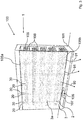
- Figure 3 shows a perspective view of a freezer device according to an embodiment of the present invention.
- FIG 3 shows a freezer device 100 with a swing door system 1.
- the freezer device 100 comprises a cabinet 101 and further a top horizontal element 105a and a bottom horizontal element 105b.
- the freezer device 100 comprises six swing doors 2, 3, two of them each forming a swing door system providing a sealing function between them.
- the swing doors 2, 3 each have a transparent region 2a, 3a so that a customer in front of the freezer device 100 can see the products 109 placed on shelves 108 inside the freezer device 100 through the swing doors 2, 3 without having to open the swing doors 2, 3.
- the sealings 20, 30 between each of the two swing doors 2, 3 are transparent.
- the horizontal elements 105a, 105b provide a stop for each of the swing doors 2, 3.
- the opening direction 90 when the swing doors 2, 3 are closed is perpendicular to the swing doors 2, 3.
- the angled direction 91 of the swing doors 2, 3 is the same for all swing doors 2, 3 of the freezer device 100. All swing doors open to the right, therefore all doors are hinged at their right side when looking perpendicular to the transparent panes of the freezer device 100.
- the freezer device 100 comprises an energy source 106, which is connected with an interface 107 which enables to provide energy to a heating element or light elements inside the swing doors 2, 3.
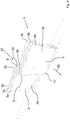
- Figure 4 shows a perspective view of a part of a swing door system according to an embodiment of the present invention.
- figure 4 shows a swing door system 1 according to Figure 1 .
- the swing door system 1 of Figure 4 comprises swing doors 2, 3 with a partial overlap 75.
- This overlap 75 is provided by the swing door 2 by the backside glass pane 5a extending further as the other glass panes 5b, 5c in the direction to the adjacent swing door 3.
- the other swing door 3 having the frontside glass pane 6c extending further as the other glass panes 6a, 6b in the direction to the adjacent swing door 3, thus providing a partial overlap 75 without touching of the extending glass panes 5a, 6c.
- Both swing doors 2, 3 further comprise a protective profile 8, 9 on the surfaces of the swing door 2, 3 in the direction to the other adjacent swing door 2, 3.
- the profiles 8, 9 have a double L-shaped form. Between these profile 8, 9 rectangular space is provided in which two sealings 20, 30 are each being attached to one of the swing doors 2, 3, in detail to the corresponding profiles 8,9. These sealings 20, 30 have triangular form therefore providing an angled sealing surface 25.
- Each of the profiles 8, 9 and each of the sealings 20, 30 can be transparent.
- a part 77 of the surface covering the profile 8, 9 of the swing door 3 and the spacers 7, when looking against the opening direction 90 can be made non-transparent to avoid a reduction of optical impression by a customer.
- a non-transparent layer can be printed on the glass pane 5c, 6c, e.g. by a non-transparent ink.
- Figure 5 shows a cross-sectional view parallel to the opening direction of the swing door system according to figure 4 .
- FIG 5 shows a swing door system 1 in a cross sectional view perpendicular to the transparent regions 2a, 3a and perpendicular to the opening direction 90.
- the rotating axis 40 of the left swing door 2 is off the center of the swing door 2 that means the center is in the plane between the middle glass pane 5b and the outer glass pane 5c near the outer surface of the swing door 2 perpendicular to transparent region 2a and next to the adjacent swing door 3 or the profile 8 for the swing door 2.
- the distance 50 between the opposite ends of the regions next to the other swing door 2, 3 including spacers 7, the profiles 8, 9, the center of the rotating axis 40 and the sealings 20, 30 forming the overlapping region 75 is here 41 mm.
- the thickness 52 of the transparent regions 2a, 3b formed in each swing door 2, 3 comprising the three corresponding glass panes 5a, 5b, 5c, 6a, 6b, 6c is 26 mm.
- the sealings 20, 30 being triangular in shape may comprise in the inside of each of the triangles a heating element 44, 45, so that the sealing 20, 30 and at least part of the glass panes 5a, 5b, 5c, 6a, 6b, 6c can be heated.
- Figure 6 shows a cross-sectional view parallel to the opening direction of the swing door system according to an embodiment of the present invention.
- Figure 6 shows in general a swing door system 1 according to Figure 2 .
- the swing door system 1 according to Figure 6 comprises two swing doors 2, 3 each of them having two glass panes 5a, 5b, 6a, 6b instead of three glass panes.
- the swing door system 1 of Figure 6 comprises a concave shaped form 21 of the left sealing 20.
- This sealing 20 of swing door 2 has an S-shaped surface towards the adjacent sealing 30 of swing door 3, the sealing 30 comprising a convex shape 22, here a kind of semi-elliptical shape as shown in Figure 2 .
- the sealing 20 of the left swing door 2 provides a stop for the closing swing door 3 when the glass panes 5a, 5b, 6a, 6b of both swing doors 2, 3 form a common plane.
- a partial form-locking connection 46 is provided. Since the S-shaped form of sealing 20 and the radius of the semi-elliptic form of the other sealing 30 are adapted to each other, the sealing surface 25 is larger compared to the sealing surface 25 of the swing door system shown in Figure 2 . In the cross-sectional view of Figure 6 the sealing surface 25 is here a kind of a quarter circle.
- Figure 7 shows a perspective view of a part of a swing door system according to an embodiment of the present invention
- Figure 8 shows a cross-sectional view parallel to the opening direction of the swing door system according to figure 7 .
- figure 7 shows in general a swing door system 1 according to Figure 4 .
- the swing door system 1 of Figure 7 comprises sealings 20, 30 being of semicircular shape.
- the sealings 20, 30 are arranged such that the sealings 20, 30 extent with their semicircular shape perpendicular to the opening direction 90 such that they are touching each other forming a sealing surface 25 in form of a single point when viewed in the cross-sectional view.
- the embodiment of Figure 7 combines in general the sealing principle of the two sealings 20, 30 of Figure 1 respectively Figure 2 with the overlapping principle of the two swing doors 2, 3 of the Figures 4 and 5 .
- the rotating axis 40 of the left swing door 2 is off the center of the swing door 2 that means the center is in the plane between the middle glass pane 5b and the outer glass pane 5c near the outer surface of the swing door 2 perpendicular to transparent region 2a and next to the adjacent swing door 3 or the profile 8 for the swing door 2.
- the distance 50 between the prominent glass pane 6c resp. 5a and the corresponding non-prominent glass panes 6a, 6b resp. 5b, 5c is here 18 mm.
- the thickness 52 of the transparent regions 2a, 3b formed in each swing door 2, 3 comprising the three corresponding glass panes 5a, 5b, 5c, 6a, 6b, 6c is 28 mm, the spacers 7 having a thickness of 8 mm and a width of 10 mm.
- the sealings 20, 30 being may comprise in the inside of each of the triangles a heating element so that the sealing 20, 30 and at least part of the glass panes 5a, 5b, 5c, 6a, 6b, 6c can be heated.
Landscapes
- Physics & Mathematics (AREA)
- Thermal Sciences (AREA)
- Engineering & Computer Science (AREA)
- Mechanical Engineering (AREA)
- Refrigerator Housings (AREA)
Priority Applications (4)
| Application Number | Priority Date | Filing Date | Title |
|---|---|---|---|
| EP19172074.7A EP3733022A1 (de) | 2019-04-30 | 2019-04-30 | Schwenktürsystem und gefriervorrichtung mit einem schwenktürsystem |
| DE202019105379.8U DE202019105379U1 (de) | 2019-04-30 | 2019-09-27 | Schwingtürsystem und Tiefkühlgerät mit einem Schwingtürsystem |
| AU2020202228A AU2020202228B2 (en) | 2019-04-30 | 2020-03-30 | Swing door system and freezer device with a swing door system |
| BR102020008645-6A BR102020008645A2 (pt) | 2019-04-30 | 2020-04-30 | sistema de portas giratórias e dispositivo congelador com um sistema de portas giratórias |
Applications Claiming Priority (1)
| Application Number | Priority Date | Filing Date | Title |
|---|---|---|---|
| EP19172074.7A EP3733022A1 (de) | 2019-04-30 | 2019-04-30 | Schwenktürsystem und gefriervorrichtung mit einem schwenktürsystem |
Publications (1)
| Publication Number | Publication Date |
|---|---|
| EP3733022A1 true EP3733022A1 (de) | 2020-11-04 |
Family
ID=66349424
Family Applications (1)
| Application Number | Title | Priority Date | Filing Date |
|---|---|---|---|
| EP19172074.7A Pending EP3733022A1 (de) | 2019-04-30 | 2019-04-30 | Schwenktürsystem und gefriervorrichtung mit einem schwenktürsystem |
Country Status (4)
| Country | Link |
|---|---|
| EP (1) | EP3733022A1 (de) |
| AU (1) | AU2020202228B2 (de) |
| BR (1) | BR102020008645A2 (de) |
| DE (1) | DE202019105379U1 (de) |
Cited By (1)
| Publication number | Priority date | Publication date | Assignee | Title |
|---|---|---|---|---|
| US20260053280A1 (en) * | 2024-08-22 | 2026-02-26 | Anthony, Inc. | Temperature-controlled enclosure with clear mullion |
Families Citing this family (2)
| Publication number | Priority date | Publication date | Assignee | Title |
|---|---|---|---|---|
| IT202000017560A1 (it) * | 2020-07-20 | 2022-01-20 | Goppion Spa | Vetrina museale con ampia apertura frontale, priva di montanti intermedi |
| WO2022049434A1 (en) * | 2020-09-03 | 2022-03-10 | Cisaplast S.P.A. | A door for a refrigeration cabinet and a method for fixing the hinge of a door |
Citations (5)
| Publication number | Priority date | Publication date | Assignee | Title |
|---|---|---|---|---|
| US5930955A (en) * | 1997-09-08 | 1999-08-03 | Butler Manufacturing Company | Door assembly |
| WO2010124341A1 (en) * | 2009-04-30 | 2010-11-04 | Maslen Technology Australia Pty Ltd | Door system for refrigerated display cabinets |
| US20140217877A1 (en) * | 2013-02-07 | 2014-08-07 | Whirlpool Corporation | Spring loaded mullion for french door refrigertor |
| US20150054396A1 (en) * | 2013-08-21 | 2015-02-26 | True Manufacturing Company, Inc. | Refrigerator Cooler with Magnetic French Door Gaskets and Method of Manufacture |
| US10240388B2 (en) * | 2014-02-11 | 2019-03-26 | Anthony, Inc. | Display case door assembly with tempered glass vacuum panel |
-
2019
- 2019-04-30 EP EP19172074.7A patent/EP3733022A1/de active Pending
- 2019-09-27 DE DE202019105379.8U patent/DE202019105379U1/de active Active
-
2020
- 2020-03-30 AU AU2020202228A patent/AU2020202228B2/en active Active
- 2020-04-30 BR BR102020008645-6A patent/BR102020008645A2/pt not_active Application Discontinuation
Patent Citations (5)
| Publication number | Priority date | Publication date | Assignee | Title |
|---|---|---|---|---|
| US5930955A (en) * | 1997-09-08 | 1999-08-03 | Butler Manufacturing Company | Door assembly |
| WO2010124341A1 (en) * | 2009-04-30 | 2010-11-04 | Maslen Technology Australia Pty Ltd | Door system for refrigerated display cabinets |
| US20140217877A1 (en) * | 2013-02-07 | 2014-08-07 | Whirlpool Corporation | Spring loaded mullion for french door refrigertor |
| US20150054396A1 (en) * | 2013-08-21 | 2015-02-26 | True Manufacturing Company, Inc. | Refrigerator Cooler with Magnetic French Door Gaskets and Method of Manufacture |
| US10240388B2 (en) * | 2014-02-11 | 2019-03-26 | Anthony, Inc. | Display case door assembly with tempered glass vacuum panel |
Non-Patent Citations (1)
| Title |
|---|
| EN23953, September 2012 (2012-09-01) |
Cited By (1)
| Publication number | Priority date | Publication date | Assignee | Title |
|---|---|---|---|---|
| US20260053280A1 (en) * | 2024-08-22 | 2026-02-26 | Anthony, Inc. | Temperature-controlled enclosure with clear mullion |
Also Published As
| Publication number | Publication date |
|---|---|
| AU2020202228A1 (en) | 2020-11-26 |
| DE202019105379U1 (de) | 2019-12-05 |
| BR102020008645A2 (pt) | 2020-11-10 |
| AU2020202228B2 (en) | 2026-04-30 |
Similar Documents
| Publication | Publication Date | Title |
|---|---|---|
| EP3748263B1 (de) | Gefrier- oder kühlvorrichtung | |
| AU2020202228B2 (en) | Swing door system and freezer device with a swing door system | |
| CN104508411B (zh) | 冰箱 | |
| EP3450892B1 (de) | Kühlthekentür und kühltheke | |
| AU2020202636B2 (en) | Swing door system and a freezer device | |
| ES2342079T3 (es) | Acristalamiento multicapa para una vitrina expositora refrigerada. | |
| TW201042225A (en) | Door system for refrigerated display cabinets | |
| US20130019616A1 (en) | Heat absorbing door for a refrigerated merchandiser | |
| AU2012284427A1 (en) | Heat absorbing door for a refrigerated merchandiser | |
| EP3735866B1 (de) | Schwenktürsystem und gefriervorrichtung | |
| BR112021024613B1 (pt) | Sistema de porta de vaivém, arranjo de porta de vaivém, e, dispositivo congelador ou refrigerador | |
| US20260053280A1 (en) | Temperature-controlled enclosure with clear mullion | |
| BR112021022155B1 (pt) | Sistema de porta oscilante e um dispositivo congelador | |
| EP3761295A1 (de) | Kühlvorrichtung und tür zur verwendung mit einer kühlvorrichtung | |
| HK40005707B (en) | Refrigerated display case door and refrigerated display case | |
| HK40005707A (en) | Refrigerated display case door and refrigerated display case |
Legal Events
| Date | Code | Title | Description |
|---|---|---|---|
| STAA | Information on the status of an ep patent application or granted ep patent |
Free format text: STATUS: EXAMINATION IS IN PROGRESS |
|
| PUAI | Public reference made under article 153(3) epc to a published international application that has entered the european phase |
Free format text: ORIGINAL CODE: 0009012 |
|
| 17P | Request for examination filed |
Effective date: 20190528 |
|
| AK | Designated contracting states |
Kind code of ref document: A1 Designated state(s): AL AT BE BG CH CY CZ DE DK EE ES FI FR GB GR HR HU IE IS IT LI LT LU LV MC MK MT NL NO PL PT RO RS SE SI SK SM TR |
|
| AX | Request for extension of the european patent |
Extension state: BA ME |
|
| RAP3 | Party data changed (applicant data changed or rights of an application transferred) |
Owner name: SCHOTT FLAT GLASS CR, S.R.O. Owner name: SCHOTT AG |
|
| P01 | Opt-out of the competence of the unified patent court (upc) registered |
Effective date: 20230516 |
|
| RAP3 | Party data changed (applicant data changed or rights of an application transferred) |
Owner name: SCHOTT TERMOFROST S.R.O. Owner name: SCHOTT AG |
|
| GRAP | Despatch of communication of intention to grant a patent |
Free format text: ORIGINAL CODE: EPIDOSNIGR1 |
|
| STAA | Information on the status of an ep patent application or granted ep patent |
Free format text: STATUS: GRANT OF PATENT IS INTENDED |
|
| INTG | Intention to grant announced |
Effective date: 20260304 |
|
| GRAS | Grant fee paid |
Free format text: ORIGINAL CODE: EPIDOSNIGR3 |
|
| GRAA | (expected) grant |
Free format text: ORIGINAL CODE: 0009210 |
|
| STAA | Information on the status of an ep patent application or granted ep patent |
Free format text: STATUS: THE PATENT HAS BEEN GRANTED |
|
| RIN1 | Information on inventor provided before grant (corrected) |
Inventor name: DIEDERICHS, JOCHEN Inventor name: SMAJSER, PETR Inventor name: RAFAJ, MARTIN Inventor name: LAMMEL, MICHAEL Inventor name: LEDERHOFER, BENJAMIN Inventor name: HELLER, MARKUS |