EP3733042A1 - Système d'affichage vidéo doté d'une superposition adaptative - Google Patents
Système d'affichage vidéo doté d'une superposition adaptative Download PDFInfo
- Publication number
- EP3733042A1 EP3733042A1 EP20171598.4A EP20171598A EP3733042A1 EP 3733042 A1 EP3733042 A1 EP 3733042A1 EP 20171598 A EP20171598 A EP 20171598A EP 3733042 A1 EP3733042 A1 EP 3733042A1
- Authority
- EP
- European Patent Office
- Prior art keywords
- video
- video image
- image
- predetermined area
- display system
- Prior art date
- Legal status (The legal status is an assumption and is not a legal conclusion. Google has not performed a legal analysis and makes no representation as to the accuracy of the status listed.)
- Pending
Links
Images

Classifications
-
- A—HUMAN NECESSITIES
- A61—MEDICAL OR VETERINARY SCIENCE; HYGIENE
- A61B—DIAGNOSIS; SURGERY; IDENTIFICATION
- A61B1/00—Instruments for performing medical examinations of the interior of cavities or tubes of the body by visual or photographical inspection, e.g. endoscopes; Illuminating arrangements therefor
- A61B1/00002—Operational features of endoscopes
- A61B1/00043—Operational features of endoscopes provided with output arrangements
- A61B1/00045—Display arrangement
-
- A—HUMAN NECESSITIES
- A61—MEDICAL OR VETERINARY SCIENCE; HYGIENE
- A61B—DIAGNOSIS; SURGERY; IDENTIFICATION
- A61B1/00—Instruments for performing medical examinations of the interior of cavities or tubes of the body by visual or photographical inspection, e.g. endoscopes; Illuminating arrangements therefor
- A61B1/00002—Operational features of endoscopes
- A61B1/00004—Operational features of endoscopes characterised by electronic signal processing
- A61B1/00009—Operational features of endoscopes characterised by electronic signal processing of image signals during a use of endoscope
- A61B1/000094—Operational features of endoscopes characterised by electronic signal processing of image signals during a use of endoscope extracting biological structures
-
- A—HUMAN NECESSITIES
- A61—MEDICAL OR VETERINARY SCIENCE; HYGIENE
- A61B—DIAGNOSIS; SURGERY; IDENTIFICATION
- A61B1/00—Instruments for performing medical examinations of the interior of cavities or tubes of the body by visual or photographical inspection, e.g. endoscopes; Illuminating arrangements therefor
- A61B1/00002—Operational features of endoscopes
- A61B1/00039—Operational features of endoscopes provided with input arrangements for the user
- A61B1/0004—Operational features of endoscopes provided with input arrangements for the user for electronic operation
-
- A—HUMAN NECESSITIES
- A61—MEDICAL OR VETERINARY SCIENCE; HYGIENE
- A61B—DIAGNOSIS; SURGERY; IDENTIFICATION
- A61B1/00—Instruments for performing medical examinations of the interior of cavities or tubes of the body by visual or photographical inspection, e.g. endoscopes; Illuminating arrangements therefor
- A61B1/00002—Operational features of endoscopes
- A61B1/00043—Operational features of endoscopes provided with output arrangements
- A61B1/00045—Display arrangement
- A61B1/0005—Display arrangement combining images e.g. side-by-side, superimposed or tiled
-
- A—HUMAN NECESSITIES
- A61—MEDICAL OR VETERINARY SCIENCE; HYGIENE
- A61B—DIAGNOSIS; SURGERY; IDENTIFICATION
- A61B1/00—Instruments for performing medical examinations of the interior of cavities or tubes of the body by visual or photographical inspection, e.g. endoscopes; Illuminating arrangements therefor
- A61B1/04—Instruments for performing medical examinations of the interior of cavities or tubes of the body by visual or photographical inspection, e.g. endoscopes; Illuminating arrangements therefor combined with photographic or television appliances
- A61B1/043—Instruments for performing medical examinations of the interior of cavities or tubes of the body by visual or photographical inspection, e.g. endoscopes; Illuminating arrangements therefor combined with photographic or television appliances for fluorescence imaging
-
- A—HUMAN NECESSITIES
- A61—MEDICAL OR VETERINARY SCIENCE; HYGIENE
- A61B—DIAGNOSIS; SURGERY; IDENTIFICATION
- A61B1/00—Instruments for performing medical examinations of the interior of cavities or tubes of the body by visual or photographical inspection, e.g. endoscopes; Illuminating arrangements therefor
- A61B1/06—Instruments for performing medical examinations of the interior of cavities or tubes of the body by visual or photographical inspection, e.g. endoscopes; Illuminating arrangements therefor with illuminating arrangements
- A61B1/0638—Instruments for performing medical examinations of the interior of cavities or tubes of the body by visual or photographical inspection, e.g. endoscopes; Illuminating arrangements therefor with illuminating arrangements providing two or more wavelengths
-
- H—ELECTRICITY
- H04—ELECTRIC COMMUNICATION TECHNIQUE
- H04N—PICTORIAL COMMUNICATION, e.g. TELEVISION
- H04N23/00—Cameras or camera modules comprising electronic image sensors; Control thereof
- H04N23/56—Cameras or camera modules comprising electronic image sensors; Control thereof provided with illuminating means
-
- H—ELECTRICITY
- H04—ELECTRIC COMMUNICATION TECHNIQUE
- H04N—PICTORIAL COMMUNICATION, e.g. TELEVISION
- H04N5/00—Details of television systems
- H04N5/222—Studio circuitry; Studio devices; Studio equipment
- H04N5/262—Studio circuits, e.g. for mixing, switching-over, change of character of image, other special effects ; Cameras specially adapted for the electronic generation of special effects
- H04N5/2628—Alteration of picture size, shape, position or orientation, e.g. zooming, rotation, rolling, perspective, translation
-
- H—ELECTRICITY
- H04—ELECTRIC COMMUNICATION TECHNIQUE
- H04N—PICTORIAL COMMUNICATION, e.g. TELEVISION
- H04N5/00—Details of television systems
- H04N5/222—Studio circuitry; Studio devices; Studio equipment
- H04N5/262—Studio circuits, e.g. for mixing, switching-over, change of character of image, other special effects ; Cameras specially adapted for the electronic generation of special effects
- H04N5/272—Means for inserting a foreground image in a background image, i.e. inlay, outlay
-
- H—ELECTRICITY
- H04—ELECTRIC COMMUNICATION TECHNIQUE
- H04N—PICTORIAL COMMUNICATION, e.g. TELEVISION
- H04N7/00—Television systems
- H04N7/18—Closed-circuit television [CCTV] systems, i.e. systems in which the video signal is not broadcast
- H04N7/183—Closed-circuit television [CCTV] systems, i.e. systems in which the video signal is not broadcast for receiving images from a single remote source
-
- H—ELECTRICITY
- H04—ELECTRIC COMMUNICATION TECHNIQUE
- H04N—PICTORIAL COMMUNICATION, e.g. TELEVISION
- H04N23/00—Cameras or camera modules comprising electronic image sensors; Control thereof
- H04N23/50—Constructional details
- H04N23/555—Constructional details for picking-up images in sites, inaccessible due to their dimensions or hazardous conditions, e.g. endoscopes or borescopes
Definitions
- the disclosure relates to a video display system and method having a first video image and a second video image overlaid on the first video image to facilitate a surgical procedure.
- Endoscopes are commonly used to provide access to body cavities while decreasing the invasiveness of a surgical procedure.
- Certain endoscopes include a video display for displaying the surgical site. It is known to have the video display provide a first video image which displays the surgical site using reflected white light and a second video image which displays the surgical site using emitted fluorescent light, for example when using a fluorescing dye such as indocyanine green ("ICG”) with an excitation light such as near-infrared light (NIR).
- ICG indocyanine green
- NIR near-infrared light
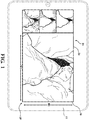
- FIG. 1 shows an embodiment of a video display system.
- the video display system displays video captured by an endoscope.
- the endoscope is configured to capture the surgical site in both reflected white light due to white illumination light and emitted fluorescent light due to, for example, NIR excitation light.
- the fluorescent light is illustratively depicted as fluorescence due to excitation of ICG.
- the video display system includes a display device, which outputs a video image.
- the video image may be partitioned into four displays.
- the first display also referenced as the main display as the first display is larger than the other displays, is shown on the right side of the video image depicting an enlarged overlay image.
- the surgical site is displayed using both reflected white light and emitted fluorescent light that has been colored by image processing, which helps features such as blood flow, tumors, malignant melanoma and the like become more visible.
- On the left side are three different images.
- the top image shows a white light image of the surgical site.
- the middle image shows a grayscale image of the fluorescent light of the surgical site.
- the grayscale image is due to the fluorescence occurring in a wavelength outside the visible spectrum yet detected as luminance by the image sensor.
- the middle image may show another image corresponding to a wavelength range outside or inside the visible spectrum as known in procedures involving photodynamic diagnosis (PDD), autofluorescence, fluorescein, and the like.
- the middle image may be pseudo-colored by assigning colors to gray values based on specific criterion.
- the bottom image shows the overlay image that appears enlarged on the right.
- the overlay image shows how overlaying the a pseudo-colored fluorescent light image on top of the white light image may highlight areas of ICG concentration but may also obscure anatomical features of the white light image where excess ICG concentration occurs.
- the system allows the user to select between one of the three images shown on the main display. As shown, such systems require the surgeon to view any one of the three types of display in the main display. For instance, the user may select the white light video, the grayscale video, or the overlay video. In some instances, it is desirable to view the white light video in the main display and reference the overlay video on one of the partitioned displays, or vice-versa as the overlay video obscures certain anatomical features clearly shown in the white light video.
- a video display system for use in a medical procedure and an endoscopic system includes a first video image displaying a white light video of the surgical site.
- the first video image has a first predetermined area.
- a second video image is overlaid on top of the first video image.
- the second video image displays a fluorescent light video, which is centered on the surgical site.
- the second video image has a second predetermined area, which is smaller than the first predetermined area to define a boundary of white light video, which surrounds the second video image.
- the surgeon is able to view the surgical site in both a fluorescent light video image and a white light video image wherein the white light video image is able to point out anatomical features so as to allow the surgeon to quickly reference where the fluorescent light video image is with respect to the anatomical features of the surgical site.
- the boundary is a pixelated line what surrounds an entire periphery of the second video image wherein an input may be provided to adjust the thickness of the boundary.
- the size of the second video image may be adjusted to increase or decrease the area of the first video image.
- the transparency of the second video image may be adjusted.
- the video display system may include an image processor configured to detect a tool.
- the image processor may be configured to detect a cutting tool, wherein the image processor detects the presence of a cutting tool as the cutting tool enters the video display.
- the video display system may be configured to automatically center the second video image on the tool to move the second display with respect to the movement of the tool within the surgical site.
- the video display system includes a first video image displaying a white light video of a surgical site.
- the first video image has a first predetermined area.
- a second video image is overlaid on the first video image.
- the second video image is displayed as a fluorescent light video depicting, for example, ICG fluorescence.
- the second video image is centered on the surgical site and includes a second predetermined area.
- the second predetermined area is smaller than the first predetermined area to define a boundary of white light video.
- the video display system 10 is illustratively shown.
- a description of video display system 10 is provided within the context of an endoscopic system 100.
- the video display system 10 may be utilized in other applications, illustratively including an exoscope, borescopes and other systems having two or more illumination-types and one or more image sensors.
- the video display system 10 is described with respect to medical applications using fluorescing dye, it should be understood that industrial applications using other combinations of illumination or excitation light types such as white light, nonvisible light (ultraviolet, infrared, or other), or light within narrow wavelength ranges (visible or nonvisible) may benefit from the same principles.
- the endoscopic system 100 includes an endoscope 102 having a camera head unit 104 coupled to the endoscope 102 by optics or optical fiber.
- the camera head unit 104 is in communication with a camera controller unit 106, through either cable or a wireless connection.
- the camera control unit 106 controls various processing functions of the camera head unit 104.
- the camera controller unit 106 may provide a timing signal to the camera head unit 104 to control the actuation of an image sensor 108 and a light source 110 and process the image data from the image sensor 108 to generate a video stream.
- the light source 110 may generate a timing signal independently of the camera controller unit 106 such that the camera controller unit 106 and the light source 110 operate independently.
- the light source 110 is configured to illuminate the surgical site of the endoscope 102 and the image sensor 108 is configured to collect image data from the light source 110.
- the light source 110 may be formed of one or more light-emitting diodes.
- the light source 110 may be configured to generate electromagnetic radiation in the visible spectrum commonly called white light and electromagnetic radiation outside the visible spectrum such as near infrared (NIR) excitation light so as to provide for fluorescent imaging such as an indocyanine green (ICG).
- NIR near infrared
- ICG indocyanine green
- Other light-emitting diodes may be used to produce various other excitation lights at wavelengths associated with other dyes and auto-fluorescing tissues, proteins, and chemicals of differing procedures.
- the light source 110 is configured to switch between illuminating with white light and excitation light.
- the image sensor 108 is actuated to collect image data for both the white light and excitation light sequences.
- the light source 110 is configured to illuminate with white light and excitation light simultaneously.
- the image sensor 108 is configured to provide an image of the body cavity thereby allowing the surgeon to locate the treatment area and monitor the surgical procedure.
- the image sensor 108 can be a complementary metal oxide semiconductor "CMOS” or a charged coupled device “CCD". It should be appreciated that any pixelated image sensor 108 currently known or later developed may be modified and adopted for use herein.
- the image sensor 108 is configured to receive electromagnetic radiation in the visible spectrum and in the ultraviolet range between about 800 nanometers to 1200 nanometers associated with a particular field of view.
- the endoscopic system 100 may include a pair of image sensors 108, wherein one of the image sensors 108 is configured to receive electromagnetic radiation in the visible spectrum with a particular field of view and the other of the image sensors 108 is configured to receive electromagnetic radiation in the ultraviolet range between about 800 nanometers to 1200 nanometers associated with the same particular field of view.
- One skilled in the art would recognize that various systems using combinations of one or more image sensors 108 may benefit from the principles of the present disclosure.
- the video display system 10 includes a display unit 12.
- the display unit 12 is coupled to the display controller unit 112.
- the image sensor 108 delivers image data to the camera controller unit 106, which processes the image data, and outputs processed image data to the display controller unit 112.
- the display controller unit 112 may arrange videos and images based on the processed image data on the monitor 12 in various ways.
- the camera controller unit 106 may provide the image data to the display controller, which includes an image processor 113.
- the image processor 113 further configures the processed image data collected by the image sensor 108 from both reflected white light and emitted fluorescent light to generate a video image 14, in particular, a white light video image and a fluorescent light video image.
- the white light and fluorescent light videos are simultaneously displayed to the display unit.
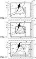
- FIG. 3 shows the display unit 12 displaying the video image 14.
- the video image includes a first video image 16 displaying a white light video having a predetermined field of view of a surgical site, the field of view may be determined by the size of the image sensor 108 and the function of the image processor 113 as is known by those skilled in the art. For instance, the field of view of the image sensor 108 may be purposefully narrowed by digital cropping performed by the image processor 113.
- the first video image 16 includes a first predetermined area 18, which defines a first width "W1", and a first height "H1" of the video image 14.
- the video image 14 further includes a second video image 20.
- the second video image 20 is overlaid on the first video image 16 wherein the images of the second video image 20 are aligned to the images of the first video image 16.
- the second video image 20 displays a fluorescent light video, which is centered on the surgical site and aligned with the first video image 16.
- the second video image 20 has a second predetermined area 22, which defines a second width "W2" and a second height "H2" of the video image 14.
- the second predetermined area 22 is smaller than the first predetermined area 18 so as to define a boundary 24 of white light video surrounding the second video image 20.
- FIG. 3 depicts a video display system 10, which allows the surgeon to manipulate a cutting tool 26 (not shown) within the surgical site and providing anatomical references to help the surgeon place the tool 26 in the proper location.
- FIG. 4 depicts an aspect of the video display system 10 wherein the white light boundary 24 surrounds the peripheral edges of the second video image 20.
- FIG. 4 depicts an aspect of the video display system 10 wherein an input 28 may be used to differentiate the boundary 24 of white light video from fluorescent light video.
- FIG. 4 shows the input 28 being configured to increase the thickness of a pixelated boundary, which defines a frame 30.
- the frame 30 delineating the white light boundary 24 from the second video image 20 is thickened relative to what is shown in FIG. 3 .
- the frame 30 is shown in a color different from the pseudo-coloring used with the fluorescent light video shown in the second video image 20.
- the input 28 may be further configured to adjust the transparency of the frame 30, change a color of the frame 30, or remove the frame 30 in its entirety.
- the video image 14 may be optimized to the surgeon's preference to help the surgeon perform the surgical procedure.
- FIG. 5 depicts another aspect of the video display system 10 wherein the second video image 20 is enlarged with respect to the video image 14 shown in FIGS. 3 and 4.
- FIG. 5 shows the second video image 20 occupying a greater area relative to the second video image 20 shown in FIG. 3 .
- the adjustment of the second video image 20 may be done by the image processor 113.
- the size of the second predetermined area 22 may be programmed.
- the video display system 10 may be configured to adjust the size of the programmed second predetermined area 22 to accommodate the surgeon's preference.
- the transparency of the second video image 20 may also be adjusted in addition to or irrespective of the size of the second predetermined area 22.
- the video display system 10 includes a first image sensor 108a and a second image sensor 108b.
- the first image sensor 108a has a predetermined pixel array configured to have a predetermined field of view.
- the first image sensor 108a is configured to process white light image.
- the second image sensor 108b has a pixel array of the same dimension as the first image sensor 108a and is configured to have the same field of view as the first image sensor 108a.
- the second image sensor 108b is configured to gather near infrared image data such as for ICG applications.
- the image processor 113 crops the image generated by the second image sensor 108b so as to produce the second video image 20 which is smaller in size relative to the first video image 16. As the first and second image sensors 108a, 108b are of the same dimension and have the same field of view, cropping the boundaries of the second video image 20 reduces the size. The image processor 113 then centers the second video image 20 with respect to the first video image 16.
- a single image sensor 108 may be used.
- the size of the second video image 20 is again cropped by the image processor 113.
- the input 28 may be configured to provide options for enlarging or decreasing the second video image 20 relative to the first video image 16.
- the second video image 20 is always centered with respect to the first video image 16.
- the first image sensor 108a is configured to capture white light image data so as to generate the first video image 16 as a white light video.
- the first image sensor 108a may generate the first video image 16 with a first predetermined pixel matrix having a first resolution.
- the second image sensor 108b is configured to capture near infrared image data so as to generate the second video image 20, which is a fluorescent light video.
- the second image sensor 108b has a second predetermined pixel matrix having a second resolution less than the first resolution.
- the second image sensor 108b may be positioned relative to various optical features (prisms, lenses, and beam splitters) such that the second video image 20 captures light at the same focal distance.
- the first image sensor 108a and the second image sensor 108b are arranged so as to be centered on the same point, thus the center of each of the first and second video images 16, 20 are the same and can combined with no need for cropping the second video image 20. Accordingly, it should be appreciated that any methods currently known or later developed may be used to produce a second video image 20 of colored light which is smaller than the first video image 16 of white light and the methods and systems described herein are provided for illustrative purposes and are not limiting to the scope of the appended claims.
- the video display system 10 may be configured to move the second video image 20 with respect to a surgical tool 26.
- the tool 26 is shown as a cutting tool 26 configured to remove tissue.
- the image processor 113 may be configured to detect the tool 26.
- the video display system 10 may include a database 114 storing a plurality of different tools 26, wherein through known processes such as edge detection, the image processor 113 may detect the presence of the tool 26 within the video image 14.
- the video display system 10 is configured to move and adjust the video image 14 with respect to the movement of the tool 26 as described in greater detail below.
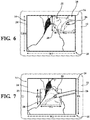
- FIG. 6 shows the tool 26 being introduced into an upper right hand corner of the video image 14.
- the tool 26 is detected by the image processor 113 and the second video image 20 is moved over to the upper right hand corner of the video image 14 so as to be off-center with respect to the first video image 16.
- the white light boundary 24 is overshadowed by the second video image 20 with respect to the upper right hand corner of the video display.
- the white light boundary 24 may overshadow the second video image 20 by including a minimum boundary size.
- additional portions of the first video image 16 may be revealed.
- the second video image 20 may be a fixed width "W2" and a fixed height "H2" that shifts with movement of the tool 26.
- a minimum white light boundary 24 may remain, regardless of the movement of the second video image 20.
- the white light boundary 24 may increase in areas of the video image 14 further away from the tool 26.
- FIG. 7 shows the second video image 20 being moved to the center of the video image 14 in correlation to the movement of the cutting tool 26. It should be appreciated that the second video image 20 may move to other areas within the video image 14 upon movement of the cutting tool 26.
- the video display system 10 may include an input 28 which allows for the user to choose one of two modes of operation wherein in a first mode of operation the second video image 20 detects and automatically centers itself around the tool 26 upon the detection of the tool 26 and in a second mode of operation, the second video image 20 remains stationary with respect to the first video image 16 and stays centered with respect to the first video image 16.
- the second video image 20 may be moved to any location within the field of view of the image sensor 108 so as to provide the surgeon with details regarding tissue perfusion and the like in any area of the field of view of the endoscope 102.
- Any input 28 currently known or later developed may be modified for use herein, illustratively including a mouse, voice command, eyeglasses, keyboard or the like.
- a video display system 10 and an endoscopic system 100 which helps the surgeon conduct a surgical procedure by providing the surgeon with a visible reference of the surgical area.
- the video image 14 includes a first video image 16 having a first predetermined area 18 and a second video image 20 overlaid on top of the first video image 16.
- the second video image 20 has a second predetermined area 22, which is smaller than the first predetermined area 18 so as to form a boundary 24 of white light video image.
- the boundary 24 of white light video image provides a clearer image of the anatomy of the surgical site relative to the fluorescent light video image of the second video image 20.
- the second video image 20 provides details as to features relating to the treatment of the surgical site such as blood flow, tumors, malignant melanoma and the like.
- the video display system 10 and the endoscopic system 100 location of the tool 26 with respect to the treatment site may be easily done by reference to the boundary 24 of the anatomy shown in a white light image.
- the video display system 10 and the endoscopic system 100 disclosed herein is customizable based upon the user preference, wherein the dimension of the second video image 20 may be increased or decreased to suit the surgeon's preference.
- the second video image 20 may be reduced to show only the area surrounding the surgical area, e.g. around the tool 26, alternatively the second video image 20 may be enlarged so as to cover the entirety of first video image 16.
- the second video image 20 may also be adjusted to increase or decrease the transparency of the second video image 20. For instance, it may be preferable to reduce the size of the second video image 20 but increase the intensity of the second video image 20 so as to better show features such as blood flow, tumors, malignant melanoma and the like.
- the video display system 10 and the endoscopic system 100 disclosed herein may be configured to detect a tool 26.
- the second video image 20 is moved to the position of the tool 26.
- the second video image 20 may be manually moved by the surgeon relative to the first video image 16, such as what is illustratively shown in FIG. 6 .
- FIG. 6 is provided to show the automatic movement of the second video image 20 is response to the detection of a tool 26, it should be appreciated that the teachings of FIG. 6 is not limited to the feature of detecting a tool 26.
Landscapes
- Health & Medical Sciences (AREA)
- Life Sciences & Earth Sciences (AREA)
- Surgery (AREA)
- Engineering & Computer Science (AREA)
- Radiology & Medical Imaging (AREA)
- Heart & Thoracic Surgery (AREA)
- Biophysics (AREA)
- Nuclear Medicine, Radiotherapy & Molecular Imaging (AREA)
- Optics & Photonics (AREA)
- Pathology (AREA)
- Veterinary Medicine (AREA)
- Public Health (AREA)
- Biomedical Technology (AREA)
- Physics & Mathematics (AREA)
- Medical Informatics (AREA)
- Molecular Biology (AREA)
- Animal Behavior & Ethology (AREA)
- General Health & Medical Sciences (AREA)
- Signal Processing (AREA)
- Multimedia (AREA)
- Endoscopes (AREA)
Applications Claiming Priority (1)
| Application Number | Priority Date | Filing Date | Title |
|---|---|---|---|
| US16/400,255 US11730340B2 (en) | 2019-05-01 | 2019-05-01 | Video display system having an adaptive overlay |
Publications (1)
| Publication Number | Publication Date |
|---|---|
| EP3733042A1 true EP3733042A1 (fr) | 2020-11-04 |
Family
ID=70470903
Family Applications (1)
| Application Number | Title | Priority Date | Filing Date |
|---|---|---|---|
| EP20171598.4A Pending EP3733042A1 (fr) | 2019-05-01 | 2020-04-27 | Système d'affichage vidéo doté d'une superposition adaptative |
Country Status (2)
| Country | Link |
|---|---|
| US (2) | US11730340B2 (fr) |
| EP (1) | EP3733042A1 (fr) |
Cited By (1)
| Publication number | Priority date | Publication date | Assignee | Title |
|---|---|---|---|---|
| EP4509085A1 (fr) * | 2023-08-16 | 2025-02-19 | Covidien LP | Système robotique chirurgical à commande automatisée de faible visibilité |
Families Citing this family (1)
| Publication number | Priority date | Publication date | Assignee | Title |
|---|---|---|---|---|
| US12615427B2 (en) * | 2022-12-09 | 2026-04-28 | Stryker Corporation | Visible fluorescent viewing system |
Citations (9)
| Publication number | Priority date | Publication date | Assignee | Title |
|---|---|---|---|---|
| EP1051104A1 (fr) * | 1998-01-26 | 2000-11-15 | Massachusetts Institute Of Technology | Imagerie endoscopique par fluorescence |
| US20090192390A1 (en) * | 2008-01-24 | 2009-07-30 | Lifeguard Surgical Systems | Common bile duct surgical imaging system |
| EP2526853A1 (fr) * | 2010-03-09 | 2012-11-28 | Olympus Corporation | Dispositif d'endoscope fluorescent |
| EP2754380A1 (fr) * | 2011-09-08 | 2014-07-16 | Olympus Corporation | Dispositif d'observation de fluorescence |
| US20150042774A1 (en) * | 2013-08-06 | 2015-02-12 | Mitsubishi Electric Engineering Company, Limited | Image Pickup Device and Image Pickup Method |
| EP2932882A1 (fr) * | 2012-12-13 | 2015-10-21 | Olympus Corporation | Dispositif d'observation fluorescent |
| US20160262602A1 (en) * | 2015-03-09 | 2016-09-15 | Steven Sounyoung Yu | Laparoscopic Cholecystectomy With Fluorescence Cholangiography |
| WO2016154589A1 (fr) * | 2015-03-25 | 2016-09-29 | Camplex, Inc. | Systèmes et affichages de visualisation à usage chirurgical |
| WO2018217951A1 (fr) * | 2017-05-24 | 2018-11-29 | Camplex, Inc. | Systèmes de visualisation chirurgicale et dispositifs d'affichage |
Family Cites Families (18)
| Publication number | Priority date | Publication date | Assignee | Title |
|---|---|---|---|---|
| JP2001299676A (ja) | 2000-04-25 | 2001-10-30 | Fuji Photo Film Co Ltd | センチネルリンパ節検出方法および検出システム |
| US8229548B2 (en) * | 2002-03-12 | 2012-07-24 | Beth Israel Deaconess Medical Center | Medical imaging systems |
| US7794396B2 (en) * | 2006-11-03 | 2010-09-14 | Stryker Corporation | System and method for the automated zooming of a surgical camera |
| US8155479B2 (en) * | 2008-03-28 | 2012-04-10 | Intuitive Surgical Operations Inc. | Automated panning and digital zooming for robotic surgical systems |
| US10507065B2 (en) * | 2009-05-29 | 2019-12-17 | Jack Wade | System and method for enhanced data analysis with video enabled software tools for medical environments |
| JP2011229850A (ja) * | 2010-04-30 | 2011-11-17 | Fujifilm Corp | 内視鏡装置、方法およびプログラム |
| CN103068294B (zh) * | 2011-01-24 | 2015-06-24 | 奥林巴斯医疗株式会社 | 医疗设备 |
| US20120197086A1 (en) * | 2011-01-31 | 2012-08-02 | Nellcor Puritan Bennett Llc | Medical visualization technique and apparatus |
| EP2735257A4 (fr) | 2011-07-22 | 2015-05-27 | Olympus Corp | Système d'endoscopie à fluorescence |
| JP6103824B2 (ja) * | 2012-06-04 | 2017-03-29 | オリンパス株式会社 | 蛍光内視鏡装置 |
| US9629523B2 (en) * | 2012-06-27 | 2017-04-25 | Camplex, Inc. | Binocular viewing assembly for a surgical visualization system |
| US9443335B2 (en) * | 2013-09-18 | 2016-09-13 | Blackberry Limited | Using narrow field of view monochrome camera for producing a zoomed image |
| KR102245193B1 (ko) * | 2014-03-13 | 2021-04-28 | 삼성메디슨 주식회사 | 의료 진단 장치 및 그 동작 방법 |
| KR101751140B1 (ko) * | 2015-12-24 | 2017-06-26 | 삼성전기주식회사 | 이미지 센서 및 카메라 모듈 |
| US10708478B2 (en) * | 2016-03-23 | 2020-07-07 | Karl Storz Imaging, Inc. | Image transformation and display for fluorescent and visible imaging |
| EP3890582B1 (fr) * | 2018-12-05 | 2025-09-17 | Intuitive Surgical Operations, Inc. | Combinaison d'informations d'infrarouge proche avec des images en couleur dans une chirurgie guidée par image |
| WO2020117941A1 (fr) * | 2018-12-05 | 2020-06-11 | Stryker Corporation | Systèmes et procédés d'affichage de données d'imagerie médicale |
| EP3958724A4 (fr) * | 2019-04-26 | 2023-01-11 | ChemImage Corporation | Produit d'imagerie hybride et système endoscopique hybride |
-
2019
- 2019-05-01 US US16/400,255 patent/US11730340B2/en active Active
-
2020
- 2020-04-27 EP EP20171598.4A patent/EP3733042A1/fr active Pending
-
2023
- 2023-03-14 US US18/183,683 patent/US20230218145A1/en not_active Abandoned
Patent Citations (9)
| Publication number | Priority date | Publication date | Assignee | Title |
|---|---|---|---|---|
| EP1051104A1 (fr) * | 1998-01-26 | 2000-11-15 | Massachusetts Institute Of Technology | Imagerie endoscopique par fluorescence |
| US20090192390A1 (en) * | 2008-01-24 | 2009-07-30 | Lifeguard Surgical Systems | Common bile duct surgical imaging system |
| EP2526853A1 (fr) * | 2010-03-09 | 2012-11-28 | Olympus Corporation | Dispositif d'endoscope fluorescent |
| EP2754380A1 (fr) * | 2011-09-08 | 2014-07-16 | Olympus Corporation | Dispositif d'observation de fluorescence |
| EP2932882A1 (fr) * | 2012-12-13 | 2015-10-21 | Olympus Corporation | Dispositif d'observation fluorescent |
| US20150042774A1 (en) * | 2013-08-06 | 2015-02-12 | Mitsubishi Electric Engineering Company, Limited | Image Pickup Device and Image Pickup Method |
| US20160262602A1 (en) * | 2015-03-09 | 2016-09-15 | Steven Sounyoung Yu | Laparoscopic Cholecystectomy With Fluorescence Cholangiography |
| WO2016154589A1 (fr) * | 2015-03-25 | 2016-09-29 | Camplex, Inc. | Systèmes et affichages de visualisation à usage chirurgical |
| WO2018217951A1 (fr) * | 2017-05-24 | 2018-11-29 | Camplex, Inc. | Systèmes de visualisation chirurgicale et dispositifs d'affichage |
Cited By (1)
| Publication number | Priority date | Publication date | Assignee | Title |
|---|---|---|---|---|
| EP4509085A1 (fr) * | 2023-08-16 | 2025-02-19 | Covidien LP | Système robotique chirurgical à commande automatisée de faible visibilité |
Also Published As
| Publication number | Publication date |
|---|---|
| US20200345204A1 (en) | 2020-11-05 |
| US11730340B2 (en) | 2023-08-22 |
| US20230218145A1 (en) | 2023-07-13 |
Similar Documents
| Publication | Publication Date | Title |
|---|---|---|
| JP7086121B2 (ja) | 波長帯選択による画像化を用いた尿管検出 | |
| US9906739B2 (en) | Image pickup device and image pickup method | |
| US11221296B2 (en) | Imaging system | |
| US20180033142A1 (en) | Image-processing apparatus, biological observation apparatus, and image-processing method | |
| JP7135082B2 (ja) | 内視鏡装置、内視鏡装置の作動方法、及びプログラム | |
| JP6779089B2 (ja) | 内視鏡システム及び内視鏡システムの駆動方法 | |
| US10517472B2 (en) | Endoscope system | |
| JP6827516B2 (ja) | 内視鏡システム及び内視鏡システムの駆動方法 | |
| JP2012065698A (ja) | 手術支援システムおよびそれを用いた手術支援方法 | |
| CA2906056A1 (fr) | Dispositif d'imagerie medicale et ses procedes d'utilisation | |
| CA2746243A1 (fr) | Equipement pour la vision infrarouge de structures anatomiques et procedes de traitement de signaux correspondants | |
| US12373973B2 (en) | Medical image processing apparatus, endoscope system, medical image processing method, and program | |
| US20230218145A1 (en) | Endoscopic system and method for displaying an adaptive overlay | |
| US11689689B2 (en) | Infrared imaging system having structural data enhancement | |
| US12355935B2 (en) | Medical imaging system, medical imaging device, and operation method | |
| EP3241481A1 (fr) | Endoscope à double trajet | |
| CN115361898B (zh) | 医疗图像处理装置、内窥镜系统及医疗图像处理装置的工作方法、非暂时性计算机可读介质 | |
| US11684238B2 (en) | Control device and medical observation system | |
| JP2002345739A (ja) | 画像表示装置 | |
| US12102296B2 (en) | Medical imaging system, medical imaging device, and operation method | |
| US20220022728A1 (en) | Medical system, information processing device, and information processing method | |
| JP2020163037A (ja) | 医療システム、情報処理装置及び情報処理方法 | |
| JP7596365B2 (ja) | 画像処理装置、画像処理方法、ナビゲーション方法及び内視鏡システム | |
| JP5160958B2 (ja) | 眼底撮影装置及び眼底画像処理装置 | |
| EP4691339A1 (fr) | Dispositif de génération d'images, système d'observation médicale, et procédé de génération d'images |
Legal Events
| Date | Code | Title | Description |
|---|---|---|---|
| PUAI | Public reference made under article 153(3) epc to a published international application that has entered the european phase |
Free format text: ORIGINAL CODE: 0009012 |
|
| STAA | Information on the status of an ep patent application or granted ep patent |
Free format text: STATUS: THE APPLICATION HAS BEEN PUBLISHED |
|
| AK | Designated contracting states |
Kind code of ref document: A1 Designated state(s): AL AT BE BG CH CY CZ DE DK EE ES FI FR GB GR HR HU IE IS IT LI LT LU LV MC MK MT NL NO PL PT RO RS SE SI SK SM TR |
|
| AX | Request for extension of the european patent |
Extension state: BA ME |
|
| STAA | Information on the status of an ep patent application or granted ep patent |
Free format text: STATUS: REQUEST FOR EXAMINATION WAS MADE |
|
| 17P | Request for examination filed |
Effective date: 20210419 |
|
| RBV | Designated contracting states (corrected) |
Designated state(s): AL AT BE BG CH CY CZ DE DK EE ES FI FR GB GR HR HU IE IS IT LI LT LU LV MC MK MT NL NO PL PT RO RS SE SI SK SM TR |
|
| STAA | Information on the status of an ep patent application or granted ep patent |
Free format text: STATUS: EXAMINATION IS IN PROGRESS |
|
| 17Q | First examination report despatched |
Effective date: 20230303 |
|
| P01 | Opt-out of the competence of the unified patent court (upc) registered |
Effective date: 20230527 |