EP3733074B1 - Dispositif d'imagerie ct par raxons x - Google Patents
Dispositif d'imagerie ct par raxons x Download PDFInfo
- Publication number
- EP3733074B1 EP3733074B1 EP18895193.3A EP18895193A EP3733074B1 EP 3733074 B1 EP3733074 B1 EP 3733074B1 EP 18895193 A EP18895193 A EP 18895193A EP 3733074 B1 EP3733074 B1 EP 3733074B1
- Authority
- EP
- European Patent Office
- Prior art keywords
- ray
- physique
- turning
- subject
- imaging
- Prior art date
- Legal status (The legal status is an assumption and is not a legal conclusion. Google has not performed a legal analysis and makes no representation as to the accuracy of the status listed.)
- Active
Links
Images








Classifications
-
- A—HUMAN NECESSITIES
- A61—MEDICAL OR VETERINARY SCIENCE; HYGIENE
- A61B—DIAGNOSIS; SURGERY; IDENTIFICATION
- A61B6/00—Apparatus or devices for radiation diagnosis; Apparatus or devices for radiation diagnosis combined with radiation therapy equipment
- A61B6/44—Constructional features of apparatus for radiation diagnosis
- A61B6/4429—Constructional features of apparatus for radiation diagnosis related to the mounting of source units and detector units
- A61B6/4435—Constructional features of apparatus for radiation diagnosis related to the mounting of source units and detector units the source unit and the detector unit being coupled by a rigid structure
-
- A—HUMAN NECESSITIES
- A61—MEDICAL OR VETERINARY SCIENCE; HYGIENE
- A61B—DIAGNOSIS; SURGERY; IDENTIFICATION
- A61B6/00—Apparatus or devices for radiation diagnosis; Apparatus or devices for radiation diagnosis combined with radiation therapy equipment
- A61B6/02—Arrangements for diagnosis sequentially in different planes; Stereoscopic radiation diagnosis
- A61B6/027—Arrangements for diagnosis sequentially in different planes; Stereoscopic radiation diagnosis characterised by the use of a particular data acquisition trajectory, e.g. helical or spiral
-
- A—HUMAN NECESSITIES
- A61—MEDICAL OR VETERINARY SCIENCE; HYGIENE
- A61B—DIAGNOSIS; SURGERY; IDENTIFICATION
- A61B6/00—Apparatus or devices for radiation diagnosis; Apparatus or devices for radiation diagnosis combined with radiation therapy equipment
- A61B6/02—Arrangements for diagnosis sequentially in different planes; Stereoscopic radiation diagnosis
- A61B6/03—Computed tomography [CT]
- A61B6/032—Transmission computed tomography [CT]
- A61B6/035—Mechanical aspects of CT
-
- A—HUMAN NECESSITIES
- A61—MEDICAL OR VETERINARY SCIENCE; HYGIENE
- A61B—DIAGNOSIS; SURGERY; IDENTIFICATION
- A61B6/00—Apparatus or devices for radiation diagnosis; Apparatus or devices for radiation diagnosis combined with radiation therapy equipment
- A61B6/04—Positioning of patients; Tiltable beds or the like
- A61B6/0487—Motor-assisted positioning
-
- A—HUMAN NECESSITIES
- A61—MEDICAL OR VETERINARY SCIENCE; HYGIENE
- A61B—DIAGNOSIS; SURGERY; IDENTIFICATION
- A61B6/00—Apparatus or devices for radiation diagnosis; Apparatus or devices for radiation diagnosis combined with radiation therapy equipment
- A61B6/44—Constructional features of apparatus for radiation diagnosis
- A61B6/4429—Constructional features of apparatus for radiation diagnosis related to the mounting of source units and detector units
- A61B6/4452—Constructional features of apparatus for radiation diagnosis related to the mounting of source units and detector units the source unit and the detector unit being able to move relative to each other
-
- A—HUMAN NECESSITIES
- A61—MEDICAL OR VETERINARY SCIENCE; HYGIENE
- A61B—DIAGNOSIS; SURGERY; IDENTIFICATION
- A61B6/00—Apparatus or devices for radiation diagnosis; Apparatus or devices for radiation diagnosis combined with radiation therapy equipment
- A61B6/50—Apparatus or devices for radiation diagnosis; Apparatus or devices for radiation diagnosis combined with radiation therapy equipment specially adapted for specific body parts; specially adapted for specific clinical applications
- A61B6/51—Apparatus or devices for radiation diagnosis; Apparatus or devices for radiation diagnosis combined with radiation therapy equipment specially adapted for specific body parts; specially adapted for specific clinical applications for dentistry
-
- A—HUMAN NECESSITIES
- A61—MEDICAL OR VETERINARY SCIENCE; HYGIENE
- A61B—DIAGNOSIS; SURGERY; IDENTIFICATION
- A61B6/00—Apparatus or devices for radiation diagnosis; Apparatus or devices for radiation diagnosis combined with radiation therapy equipment
- A61B6/54—Control of apparatus or devices for radiation diagnosis
- A61B6/541—Control of apparatus or devices for radiation diagnosis involving acquisition triggered by a physiological signal
-
- A—HUMAN NECESSITIES
- A61—MEDICAL OR VETERINARY SCIENCE; HYGIENE
- A61B—DIAGNOSIS; SURGERY; IDENTIFICATION
- A61B6/00—Apparatus or devices for radiation diagnosis; Apparatus or devices for radiation diagnosis combined with radiation therapy equipment
- A61B6/54—Control of apparatus or devices for radiation diagnosis
- A61B6/545—Control of apparatus or devices for radiation diagnosis involving automatic set-up of acquisition parameters
-
- A—HUMAN NECESSITIES
- A61—MEDICAL OR VETERINARY SCIENCE; HYGIENE
- A61B—DIAGNOSIS; SURGERY; IDENTIFICATION
- A61B6/00—Apparatus or devices for radiation diagnosis; Apparatus or devices for radiation diagnosis combined with radiation therapy equipment
- A61B6/54—Control of apparatus or devices for radiation diagnosis
- A61B6/547—Control of apparatus or devices for radiation diagnosis involving tracking of position of the device or parts of the device
-
- A—HUMAN NECESSITIES
- A61—MEDICAL OR VETERINARY SCIENCE; HYGIENE
- A61B—DIAGNOSIS; SURGERY; IDENTIFICATION
- A61B6/00—Apparatus or devices for radiation diagnosis; Apparatus or devices for radiation diagnosis combined with radiation therapy equipment
- A61B6/58—Testing, adjusting or calibrating thereof
- A61B6/589—Setting distance between source unit and patient
-
- A—HUMAN NECESSITIES
- A61—MEDICAL OR VETERINARY SCIENCE; HYGIENE
- A61B—DIAGNOSIS; SURGERY; IDENTIFICATION
- A61B6/00—Apparatus or devices for radiation diagnosis; Apparatus or devices for radiation diagnosis combined with radiation therapy equipment
- A61B6/50—Apparatus or devices for radiation diagnosis; Apparatus or devices for radiation diagnosis combined with radiation therapy equipment specially adapted for specific body parts; specially adapted for specific clinical applications
- A61B6/501—Apparatus or devices for radiation diagnosis; Apparatus or devices for radiation diagnosis combined with radiation therapy equipment specially adapted for specific body parts; specially adapted for specific clinical applications for diagnosis of the head, e.g. neuroimaging or craniography
Definitions
- the present invention relates to an X-ray CT imaging apparatus that performs X-ray imaging by rotating an X-ray generator and an X-ray detector around a subject.
- the subject of X-ray imaging has various sizes.
- An object of the present invention is to prevent the X-ray generator and the X-ray detector that turn around the subject from contacting with the subject.
- an X-ray CT imaging apparatus includes: a turning support that supports an X-ray generator and an X-ray detector so that the X-ray generator and the X-ray detector are opposed to each other with a subject sandwiched therebetween; a turning drive mechanism including a turning mechanism that turns the turning support about a mechanical turning axis located between the X-ray generator and the X-ray detector and a turning axis moving mechanism that moves the mechanical turning axis in a direction intersecting with an axial direction of the mechanical turning axis; a subject physique setting unit that can set a size of a physique of the subject; and a turning controller that controls the turning mechanism and the turning axis moving mechanism.
- the turning axis moving mechanism moves the mechanical turning axis in synchronization with turning of the turning support about the mechanical turning axis using the turning mechanism, and the turning support is caused to perform combined motion, which allows the X-ray generator and the X-ray detector to turn about a center of an X-ray CT imaging region, and position control of the turning axis is performed according to a size of the physique of the subject set by the subject physique setting unit.
- the drive control in which the turning support is caused to perform the combined motion is performed when the set physique of the subject is a first physique, and the drive control in which the turning support is turned while the mechanical turning axis is fixed to a position of the center of the X-ray CT imaging region is performed when the set physique of the subject is a second physique smaller than the first physique.
- a distance of the mechanical turning axis to the center of the X-ray CT imaging region is changed according to the size of the physique of the subject set by the subject physique setting unit when the turning support is caused to perform the combined motion.
- a position of the mechanical turning axis with respect to the center of the X-ray CT imaging region is controlled such that the separation distance when the set physique of the subject is the first physique is larger than the separation distance when the set physique of the subject is the second physique smaller than the first physique according to the size of the physique of the subject set by the subject physique setting unit.
- the turning axis moving mechanism rotates the mechanical turning axis about the center of the X-ray CT imaging region in synchronization with the turning of the turning support about the mechanical turning axis using the turning mechanism.
- a seventh aspect that is the X-ray CT imaging apparatus of any one of the first to sixth aspects further includes an X-ray regulating unit that adjusts a regulation amount of the X-ray generated from the X-ray generator according to a distance of the X-ray generator to the center of the X-ray CT imaging region when the X-ray generator and the X-ray detector are turned about the center of the X-ray CT imaging region.
- the mechanical turning axis is disposed along a vertical direction.
- the X-ray CT imaging is performed with a jaw region of a head of the subject as the X-ray CT imaging region.
- the X-ray CT imaging is performed with a part of a dental arch of the head of the subject as the X-ray CT imaging region.
- the X-ray generator and the X-ray detector turn around the X-ray CT imaging region to perform the X-ray CT imaging by offset scan while a part of the X-ray CT imaging region is irradiated with the X-ray generated from the X-ray generator at a position where a symmetrical axis of spread of the X-ray deviates from the center of the X-ray CT imaging region.
- a distance of the X-ray generator to the center of the X-ray CT imaging region and a distance of the X-ray detector to the center of the X-ray CT imaging region are kept constant while the X-ray CT imaging is performed by irradiating the subject with the X-ray generated from the X-ray generator.
- the subject physique setting unit sets the physique by receiving an input operation to select one of physique sizes of a plurality of selection candidates.
- the subject physique setting unit sets the physique of the subject by automatically recognizing the physique of the subject.
- the subject physique setting unit includes a measurement unit that is provided in a holder that holds the subject, and measures the physique of the subject held by the holder, and the subject physique setting unit sets the physique of the subject based on a measurement result of the measurement unit.
- the turning drive mechanism is controlled such that the X-ray generator and the X-ray detector form a panoramic imaging orbit to perform panoramic X-ray imaging of a dental arch of the subject, and a passage route of the X-ray detector is changed at least in timing of irradiating to a molar region of the dental arch with the X-ray according to the size of the physique of the subject.
- the position control of the turning axis is performed according to the size of the physique of the subject set by the subject physique setting unit. Consequently, the orbits on which the X-ray generator and the X-ray detector turn can be changed to prevent the X-ray generator and the X-ray detector that turn around the subject from contacting with the subject.
- the orbit on which the X-ray generator and the X-ray detector turn can be changed according to the size of the physique of the subject by switching the drive control in which the turning support is caused to perform the combined motion and the drive control in which the turning support is turned while the mechanical turning axis is fixed to a position of the center of the X-ray CT imaging region according to the size of the physique of the subject set by the subject physique setting unit.
- the turning support when the set physique of the subject is the relatively small second physique, the turning support is turned while the mechanical turning axis is fixed to the center position of the X-ray CT imaging region, so that the position of the mechanical turning axis is stabilized to easily obtain a clear X-ray CT image.
- the turning support is caused to perform combined motion, the X-ray generator and the X-ray detector that turn around the subject can be prevented from contacting with the subject by causing the turning support to perform the combined motion.
- the distance of the mechanical turning axis to the center of the X-ray CT imaging region is changed according to the size of the physique of the subject set by the subject physique setting unit, which allows the orbit on which the X-ray generator and the X-ray detector turn to be changed according to the size of the physique of the subject
- the position of the mechanical turning axis with respect to the center of the X-ray CT imaging region is controlled such that the separation distance when the set physique of the subject is the first physique is larger than the separation distance when the set physique of the subject is the second physique smaller than the first physique according to the size of the physique of the subject set by the subject physique setting unit, which allows the X-ray generator and the X-ray detector turn around the subject to be prevented from contacting with the subject.
- the turning axis moving mechanism rotates the mechanical turning axis about the center of the X-ray CT imaging region in synchronization with the turning of the turning support about the mechanical turning axis using the turning mechanism, which allows the X-ray generator and the X-ray detector to turn along the orbit as close as to the circle
- the X-ray generator and the X-ray detector can be turned around the axis along the vertical direction.
- the X-ray generator and the X-ray detector can be prevented from contacting with the head according to the physique of the head of the subject.
- the X-ray generator and the X-ray detector can be prevented from contacting with the head according to the physique of the head of the subject.
- the X-ray CT imaging of the X-ray CT imaging region as wide as possible can be performed by offset scan.
- the X-ray CT imaging can be performed while the magnification ratio is kept constant.
- the physique of the subject can be automatically detected and set.
- the physique of the subject can be set based on the opening degrees of the plurality of members that hold the subject.
- the magnification ratio can be adjusted by moving the X-ray detector along the X-ray irradiation direction.
- the X-ray generator can be prevented from contacting with the head when the panoramic imaging is performed.
- the X-ray CT imaging apparatus 10 is an apparatus that performs X-ray computed tomography (CT) imaging of a subject P, and includes a turning support 20, a turning drive mechanism 30, a subject physique setting unit 40, and a turning controller 60.
- CT computed tomography
- the subject physique setting unit 40 is configured to be able to set the size of the physique of the subject P.
- the size of the physique of the subject P is set to the turning controller 60.
- Information that becomes a base in setting the size of the physique of the subject P using the subject physique setting unit 40 may be obtained by receiving an input operation performed by an operator of the X-ray CT imaging apparatus 10.
- the information may be transmission X-ray image data obtained by previously imaging the subject P using the X-ray generator 22 and the X-ray detector 24.
- the information may be visible light image data obtained by imaging the subject P using an imager such as a CCD camera.
- the information may be data based on a signal output from a sensor or the like provided in the subject holder holding the subject P.
- Fig. 2 is a flowchart illustrating processing performed by the turning controller 60.
- step S1 the physique of the subject P is set in performing the X-ray CT imaging.
- step S2 a turning control content according to the size of the physique of the subject P is decided.
- the turning control content includes information about position control such as how to control the position of the mechanical turning axis X1 in turning the X-ray generator 22 and the X-ray detector 24 around the center of the X-ray CT imaging region R.
- position control such as how to control the position of the mechanical turning axis X1 in turning the X-ray generator 22 and the X-ray detector 24 around the center of the X-ray CT imaging region R.
- the following example can be considered as an example of the position control of the mechanical turning axis X1.
- the turning axis moving mechanism 38 moves the mechanical turning axis X1 in synchronization with the turning of the turning support 20 about the mechanical turning axis X1 using the turning mechanism 32.
- the turning axis moving mechanism 38 may turn the mechanical turning axis X1 around the X-ray CT imaging region R in synchronization with the turning of the turning support 20 about the mechanical turning axis X1 using the turning mechanism 32. At this point, the turning axis moving mechanism 38 may rotate the mechanical turning axis X1 with the center A of the X-ray CT imaging region R as the rotation center. In the second position control example, the mechanical turning axis X1 is fixed to the center A of the X-ray CT imaging region R when the turning mechanism 32 turns the turning support 20 about the mechanical turning axis X1.
- the trajectory along which the X-ray generator 22 and the X-ray detector 24 turn can be changed so as to be moved away from or brought close to the X-ray CT imaging region R.
- the trajectory along which the X-ray generator 22 and the X-ray detector 24 turn may be changed so as to be moved away from or brought close to the X-ray CT imaging region R.
- the trajectory along which the X-ray generator 22 and the X-ray detector 24 turn can be changed in multiple stages so as to be moved away from or brought close to the X-ray CT imaging region R.
- the X-ray CT imaging region R is a region that is set as a target of the X-ray CT imaging in the subject P.
- the X-ray CT imaging region R may be a whole or a part of the subject P.
- the X-ray CT imaging region R may be a previously-defined region as a predetermined region of the subject P, or a region set by the operator or the like each time the CT imaging is performed.
- the X-ray CT imaging region R is simply referred to as an imaging region R.
- the turning axis moving mechanism 38 controls the position of the mechanical turning axis X1 with respect to the center A of the imaging region R according to the size of the physique.
- D1 is a distance between the center A of the imaging region R and the X-ray generator 22, that D2 is a distance between the center A of the imaging region R and the X-ray detector 24, and that a separation distance D is a smaller one of the two distances D1, D2.
- the case that the physique of the subject P set by the subject physique setting unit 40 is a first physique P(L) and the case that the physique of the subject P is a second physique P(M) smaller than the first physical constitution P(L) are assumed.
- the position of the mechanical turning axis X1 is controlled such that the separation distance D when the set physique of the subject P is the relatively large first physique P(L) is greater than the separation distance D when the set physique of the subject P is the relatively small second physique P(M) according to the size of the physique of the subject P set by the subject physique setting unit 40.
- the separation distance D is the distance D2 between the center A of the imaging region R and the X-ray detector 24.
- the separation distance for the relatively large first physique P(L) is set to D(L)
- the relatively small second physique P(M) is set to D(M).
- the separation distance D(L) for the relatively large first physique is increased larger than the separation distance D(M).
- the separation distance D(L) is set to a range less than or equal to D1 of the adjusted distance, namely, a range in which the X-ray generator 22 is not brought closer to the center A of the imaging region R than the X-ray detector 24.
- the X-ray detector 24 is turned with a radius corresponding to the relatively small separation distance D(M). For this reason, the X-ray detector 24 can be turned while brought as close as possible to the second physique P(M).
- the X-ray generator 22 turns a position farther from the center A of the imaging region R than the X-ray detector 24, namely, the X-ray generator 22 turns such that a degree of separation with respect to the center A is larger than a degree of separation with respect to the center A of the X-ray detector 24.
- the X-ray detector 24 is turned with a radius corresponding to the relatively large separation distance D(L). Consequently, the X-ray detector 24 can be turned without interfering with the first physique P(L).
- the X-ray generator 22 turns a position farther from the center A of the imaging region R than the X-ray detector 24, namely, the X-ray generator 22 turns such that a degree of separation with respect to the center A is larger than a degree of separation with respect to the center A of the X-ray detector 24.
- the turning control content of the mechanical turning axis X1 according to the size of the physique can be decided by referring to the reference table previously stored in the storage according to the set sizes of a plurality of physiques.
- the reference table can be set to a table in which the turning control content of the turning axis X1 is associated with each of the plurality of physiques.
- the turning control content is defined as fixing of the mechanical turning axis X1 to a fixed position.
- the turning control content is defined as a pattern moving the mechanical turning axis X1 around the center A of the imaging region R.
- a more specific example is a pattern in which the mechanical turning axis X1 is rotated with a predetermined axis turning radius as the center A of the imaging region R as a rotation center.
- the predetermined axis turning radius may be a value previously set according to the size of the physique.
- step S3 the turning controller 60 controls the turning mechanism 32 and the turning axis moving mechanism 38 based on the decided turning control content, and the X-ray generator 22 and the X-ray detector 24 are turned around the center A of the imaging region R of the subject P.
- the X-rays emitted from the X-ray generator 22 is incident on the X-ray detector 24 through the subject P, and data used to generate the X-ray CT image is obtained.
- the X-ray CT image is generated based on this data.
- the position control of the turning axis X1 is performed according to the size of the physique of the subject P to change the turning orbits of the X-ray generator 22 and the X-ray detector 24, so that the X-ray CT imaging can be performed by bringing the X-ray detector 24 as close as possible to the subject P while the contact of the X-ray detector 24 with the subject P is prevented. Consequently, the clear X-ray image can be generated.
- Fig. 3 is a schematic diagram illustrating an entire configuration of an X-ray CT imaging apparatus 110.
- An example in which the X-ray CT imaging apparatus 110 can perform not only the X-ray CT imaging but also panoramic imaging, cephalogram imaging, and the like will be described.
- An example in which the subject of the X-ray CT imaging apparatus 110 is the head P of a human body will be described.
- the X-ray CT imaging apparatus 110 includes an imaging main body 120 and an X-ray image processing apparatus 180.
- the imaging main body 120 is an apparatus that performs the X-ray imaging such as the X-ray CT imaging to collect projection data.
- the X-ray image processing apparatus 180 is an apparatus that processes the projection data collected by the imaging main body 120 and generates various images.
- the imaging main body 120 includes a turning support 124 and a turning drive mechanism 130.
- the turning support 124 supports an X-ray generator 126 and an X-ray detector 128 such that the X-ray generator 126 and the X-ray detector 128 are opposed to each other with the head P sandwiched therebetween.
- the turning support 124 may be called a supporter that supports the X-ray generator 22 and the X-ray detector 24.
- the turning drive mechanism 130 includes a turning mechanism 132 and a turning axis moving mechanism 134.
- the turning mechanism 132 is a mechanism that turns the turning support 124 about the mechanical turning axis X1 between the X-ray generator 126 and the X-ray detector 128.
- the Z-axis direction is referred to as a Z-direction
- the Y-axis direction is referred to as a Y-direction
- the X-axis direction is referred to as an X-direction.
- the Z-axis direction can be considered as a longitudinal direction
- the X-direction and the Y-direction can also be considered as a crosswise direction.
- the longitudinal direction may be a vertical direction
- the Y-direction may be a horizontal direction.
- the turning axis moving mechanism 134 is a mechanism that moves the mechanical turning axis X1 in the direction intersecting with the mechanical turning axis X1, in this case, the direction orthogonal to the mechanical turning axis X1.
- the turning axis moving mechanism 134 is constructed with an XY-table mechanism, and the mechanical turning axis X1 is moved in the direction intersecting with the mechanical turning axis X1 by moving the turning mechanism 132 to which the mechanical turning axis X1 is connected in the direction intersecting withe the mechanical turning axis X1.
- the illustration image 195 is displayed on the lower sides of the panorama selection image 191a, the cephalogram selection image 191b, and the CT selection image 191c in the display 158a.
- the illustration image 195 is an image representing the imaging region, and a dental arch is displayed as the illustration image.
- the touch detector 158b is provided on the display 158a as a two-dimensional position detector that detects the touch position with respect to the display region.
- the touch operation is detected by the touch detector 158b. Consequently, the main body controller 150 receives whether to perform the panoramic imaging, the cephalogram imaging, or the X-ray CT imaging.
- a selection image corresponding to the physique setting image 193 or the imaging region setting image 194 is displayed according to the touch operation.
- the selection images corresponding to all the physique setting image 193 and the imaging region setting image 194 are displayed.
- actually the selection image corresponding to the touched one of the physique setting image 193 and the imaging region setting image 194 is displayed.
- a normal-size selection image 193a M size
- a large-size selection image 193b L size
- the operation to input the physique of the head P is received when the user selectively touches the normal-size selection image 193a or the large-size selection image 193b.
- a plurality of imaging region selection images 194a, 194b, 194c, 194d, and 194e are displayed when the operator touches the imaging region setting image 194.
- the plurality of imaging region selection images 194a, 194b, 194c, 194d, 194e indicate regions in which sizes (a diameter and a height) are different from one another.
- the operation to set the imaging region is received when the user selectively touches any one of the plurality of imaging region selection images 194a, 194b, 194c, 194d, 194e.
- the imaging region 195a (or the imaging region 195b) is displayed while superimposed on the illustration image 195.
- a circle having a size corresponding to the imaging region set through the imaging region setting image 194 is displayed as the imaging regions 195a, 195b.
- the imaging region 195a is an image that is displayed when the imaging region where the whole of the dental arch is set to the target is selected
- the imaging region 195b is an image that is displayed when the imaging region where a part of the dental arch is set to the target is selected.
- the operator touches any position of the illustration image 195 to move the imaging region 195b to a position where a part of the dental arch is designated.
- the imaging region can be designated at any position of the dental arch (for example, a front tooth region, a right molar region, a left molar region).
- the difference between the imaging regions 195a, 195b is illustrated with some emphasis.
- the description will be made on the assumption that the X-ray CT imaging is performed with the whole dental arch that is the jaw region of the head P as the X-ray CT imaging region R.
- the designation of the imaging mode, the setting of the physique, the designation of the imaging region, and the like are performed using the touch panel.
- various settings may be received through a switch (push button) that physically receives the operation.
- step S12 when the physique setting unit 151a receives the operation to input the physique of the head P through the operation panel apparatus 158, the setting of the physique of the head P is performed according to the received content.
- the physique setting unit 151a receives the input operation to select one of the normal-size selection image 193a and the large-size selection image 193b, which are physique sizes of a plurality of selection candidates, through the operation panel apparatus 158, thereby setting the physique of the head P.
- an X-ray regulating width (X-ray regulating hole) that should be regulated by the X-ray detector 128 can also be set in a range larger than the minimum width and in a range that prevents surroundings of the range larger than the minimum width from being excessively irradiated with the X-ray.
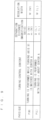
- the decision of the turning control content and the regulation amount according to the set size of physique can be performed by referring to the reference table in Fig. 9 . That is, the reference table in which the turning control content, the separation distance D (magnification m), and the regulating width W are correlated with the physique of the head P is previously registered.
- the mechanical turning axis X1 is turned while matched with the center A of the imaging region R, the separation distance D(M) (magnification m(M)), and the regulating width W(M) are correlated with one another as the turning control content.
- the mechanical turning axis X1 is turned with a radius r about the center A of the imaging region R, the separation distance D(L) (magnification factor m(L)), and a regulating width W(L) are correlated with one another as the turning control content.
- the separation distance D(M), the magnification m(M), the regulating width W(M), the separation distance D(L), the magnification m(L), the regulating width W(L), and the radius r are defined by a specific numerical value, and the physique P(L) is larger than the physique P(M), separation distance D(M) ⁇ separation distance D(L), magnification m(M) ⁇ magnification m(L), and regulating width W(M) ⁇ regulating width W(L) hold.
- step S14 the X-ray regulating unit 129 is controlled according to the regulating widths W(M), W(L) that are the decided regulation amount such that the X-ray having the width corresponding to the imaging region R is emitted from the X-ray detector 128.
- step S15 the CT imaging is performed by performing the turning control based on the decided turning control content. That is, when the X-ray CT imaging is performed by irradiating the head P with the X-ray generated from the X-ray detector 128, the position control of the turning axis X1 is performed according to the size of the physique of the head P that is the subject set by the physique setting unit 151a.
- the position of the mechanical turning axis X1 with respect to the center A of the imaging region R may be controlled according to the physique P(M) or the physique P(L) of the head P set by the physique setting unit 151a such that the separation distance D (L) when the set physique is the first physique P(L) is larger than the separation distance D(M) when the set physique is the second physique P(M) small than the first physique P(L).
- Switching of the drive control with respect to the size of the physique may be reversed depending on the position of the turning axis X1 with respect to the X-ray generator 126 and the X-ray detector 128.
- the drive control turning the turning support 124 may be performed on the first physique P(L) having the set relatively large physique of the head P while the mechanical turning axis X1 is fixed to the center position of the imaging region R, and the physique of the set head P is relatively small
- the drive control causing the turning support 124 to perform the combined motion may be performed on the second physique P(M) having the set relatively small physique of the head P.
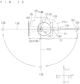
- Fig. 10 is an explanatory view illustrating turning action when the physique is the relatively small second physique P(M)
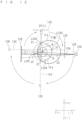
- Fig. 11 is an explanatory view illustrating turning action when the physique is the relatively large first physique P(L).
- Figs. 10 and 11 are principle explanatory views when the turning action is viewed from the Z-axis direction.
- Figs. 10 and 11 illustrate the state in which the turning support 124 is turned 180 degrees
- the CT imaging can be performed by turning the turning support 124 by 360 degrees according to the setting.
- the position of the mechanical turning axis X1 is located closer to the X-ray detector 128 than the intermediate point between the X-ray generator 126 and the X-ray detector 128 on the turning support 124.
- the turning support 124 is turned while the mechanical turning axis X1 is matched with the center A of the imaging region R.
- the X-ray generator 126 and the X-ray detector 128 turn about the mechanical turning axis X1 matched with the center A of the imaging region R.
- the X-ray regulating unit 129 forms the X-ray into an X-ray cone beam CB.
- the turning support 124 is driven by the turning drive mechanism 130, the X-ray detector 128 is located close to the +Y-direction in Figs.
- a center beam CTB that equally divided a spread angle in the x-direction of the X-ray cone beam CB has a positional relationship in which the center beam CTB passes through the center A of the imaging region R, and the positional relationship is maintained during the imaging and the turning of the turning support 124.
- the distance between the center A of the imaging region R and the X-ray generator 126 is maintained at D1
- the distance between the center A of the imaging region R and the X-ray detector 128 is maintained at D2. Because the X-ray detector 128 is located closer to the center of the imaging region R than the X-ray generator 126 on the orbits of the X-ray generator 126 and the X-ray detector 128, which are set for the imaging region R, during the X-ray imaging, the separation distance D(M) becomes the distance D2 between the center A of the imaging region R and the X-ray detector 128.
- the separation distance D(M) is set larger than the maximum distance between the center A of the imaging region R and a surface of the head P(P2) having the smaller physique P(M) in the direction orthogonal to the turning axis X1. For this reason, the X-ray detector 128 can turn around the head P(P2) without contacting with the head P(P2) having the smaller physique P(M).
- the X-ray generator 126 turns at a position farther from the center A of the imaging region R than the X-ray detector 128, so that the X-ray generator 126 can turn around the head P(P2) without contacting with the head P(P2).
- the separation distance D (not illustrated) becomes the distance between the center A of the imaging region R and the X-ray generator 126 when the X-ray generator 126 is closer to the imaging center A than the X-ray detector 128 on the orbits of the X-ray generator 126 and the X-ray detector 128, which set for the imaging region R, during the X-ray imaging.
- the imaging region R becomes the same position in the front of the head in the head P1 and the head P2, and an occipital region of the head P1 occupies a larger region than an occipital region of the head P2 on the -Y-side.
- the relatively large first physique P(L) (head P1) when the X-ray detector 128 turns in the same manner as described above, there is a possibility that the X-ray detector 128 abuts on the head P(P1) having the first physique P(L).
- the turning support 124 is turned about the mechanical turning axis X1 while the mechanical turning axis X1 is turned with the radius r about the center A of the imaging region R. That is, the mechanical turning axis X1 moves on a circular orbit CLa having the radius r. That is, the position of the mechanical turning axis X1 with respect to the center A of the imaging region R is controlled such that the mechanical turning axis X1 is moved away from the center A of the imaging region R.
- the mechanical turning axis X1 is turned with the radius r about the center A of the imaging region R by the turning axis moving mechanism 134 in synchronization with the turning of the turning support 124 about the mechanical turning axis X1 using the turning mechanism 132.
- the mechanical turning axis X1 is moved away from the center A of the imaging region R toward the side of the X-ray detector 128. That is, the mechanical turning axis X1 turns around the center A of the imaging region R while maintaining the positional relationship provided between the center A of the imaging region R and the X-ray detector 128.
- the mechanical turning axis X1 is located at a position LC1 shifted onto the +Y-side from the center A of the imaging region R in timing when the X-ray generator 126 is located on the -Y-side while the X-ray detector 128 is located on the +Y-side, the mechanical turning axis X1 is located at a position LC2 shifted onto the +X-side from the center A of the imaging region R in timing when the X-ray generator 126 is located on the -X-side while the X-ray detector 128 is located on the +X-side, and the mechanical turning axis X1 is located at a position LC3 shifted onto the -Y-side from the center A of the imaging region R in timing when the X-ray generator 126 is located on the +Y-side while the X-ray detector 128 is located on the -Y-side.
- the mechanical turning axis X1 is shifted onto the -X-side from the center A of the imaging region R.
- the synchronization between the turning of the turning support 124 about the mechanical turning axis X1 and the turning of the mechanical turning axis X1 about the center A of the imaging region R will further be described with reference to Fig. 11 .
- the mechanical turning axis X1 is located at the position LC1 deviating from the center A, and the whole imaging region R is irradiated from the -Y-direction toward the +Y-direction with the X-ray cone beam CB in the illustrated example. It is assumed that an orientation COR1 is an orientation in which the center beam CTB travels toward the imaging region R, namely, the orientation toward the center A in the illustrated example, and that an orientation XOR1 is an orientation from the mechanical turning axis X1 toward the center A.
- the whole imaging region R is irradiated from the -X-direction to the +X-direction with the X-ray cone beam CB at a point of time the mechanical turning axis X1 turns about the center A to the position LC2 deviating from the center A along the circular orbit CLa having the radius r while the turning support 124 turns about the mechanical turning axis X1.
- an orientation COR2 is the orientation in which the center beam CTB travels toward the imaging region R, namely, the orientation toward the center A in the illustrated example, and that an orientation XOR2 is the orientation from the mechanical turning axis X1 toward the center A.
- AGC1 is a displacement angle amount from the orientation COR1 to the orientation COR2
- AGX1 is a displacement angle amount from the orientation XOR1 to the orientation XOR2.
- the displacement from the orientation COR1 to the orientation COR2 and the displacement from the orientation XOR1 to the orientation XOR2 are identical to each other as a turning direction in which the center A is set to the turning center, and the displacement angle amount AGC1 and the displacement angle amount AGX1 are equal to each other.
- the turning movement of the turning support 124 is performed by the turning drive mechanism 130. In the illustrated example, the turning of the turning support 124 is performed by the turning mechanism 132, and the movement of the mechanical turning axis X1 is performed by the turning axis moving mechanism 134. The above synchronization is performed while this relationship is kept.
- the coordinate of the mechanical turning axis X1 is temporarily considered while leaving Fig. 11 .
- (X(a),Y(a)) is the coordinates of X and Y in the XYZ-coordinate system of the center A of the imaging region R
- ⁇ an angle rotating counterclockwise from the direction in which the X-ray generator 126 is located on the +X-side while the X-ray detector 128 is located on the -X-side
- the turning mechanism 132 and the turning axis moving mechanism 134 are controlled such that an X-coordinate of the mechanical turning axis X1 becomes "X(a) - rcos ⁇ " by the X-direction drive unit 136, and such that a Y-coordinate of the mechanical turning axis X1 becomes "Y(a) - rsin ⁇ " by the Y-direction drive unit 138.
- the control content can similarly be applied
- the X-ray generator 126 and the X-ray detector 128 turn about the mechanical turning axis X1.
- the distance D1 between the center A of the imaging region R and the X-ray generator 126 in the case of Fig. 10 (in the case of Fig. 10 , the distance D1 is the same as the distance between the mechanical turning axis X1 and the X-ray generator 126), the distance between the center A of the imaging region R and the X-ray generator 126 during the turning is distance D1 - radius r, and is kept constant.
- the distance D2 in the case of Fig. 10 in the case of Fig.
- the distance D2 is the same as the distance between the mechanical turning axis X1 and the X-ray detector 128), the distance between the center A of the imaging region R and the X-ray detector 128 during the turning is distance D2 + radius r, and is kept constant.
- the radius r is decided within the range of (distance D1 - radius r) ⁇ (distance D2 + radius r). For this reason, the separation distance D(L) is distance D2 + radius r.
- the separation distance D(L) is set larger than the maximum distance between the center A of the imaging region R and the surface of the head P(P1) having the larger physique P(L) in the direction orthogonal to the turning axis X1. Consequently, the X-ray detector 128 can turn around the head P(P1) having the larger physique P(L) without contacting with the head P(P1).
- the X-ray generator 126 turns at a position as far as or far away from the X-ray detector 128 with respect to the center A of the imaging region R, so that the X-ray generator 126 can turn around the head P(P1) without contacting with the head P(P1).
- the maximum distance to the surface of the head P(P1) may be set to the maximum distance in the range where the X-ray generator 126 or the X-ray detector 128 relating to the smaller separation distance D(L) turns.
- the maximum distance in the range of the movement orbit of the X-ray generator 126 or the X-ray detector 128 relating to the smaller separation distance D(L) may be targeted except for the occipital region when the X-ray generator 126 or the X-ray detector 128 relating to the smaller separation distance D(L) does not turn to the occipital region.
- a bias of the mechanical turning axis X1 with respect to the center A is generated on the side of the X-ray detector 128.
- the direction from the center A toward the mechanical turning axis X1 and the direction from the X-ray generator 126 toward the X-ray detector 128 are maintained in parallel.
- the turning center of the X-ray generator 126 and the X-ray detector 128 is referred to as an imaging turning center IC.
- the X-ray generator 126 and the X-ray detector 128 turn with the center A of the imaging region R as the imaging turning center IC.
- the imaging turning center IC may be generated when the mechanical turning axis X1 is subjected to two-dimensional movement control.
- the relatively small second physique P(M) in Fig. 10 is compared to the relatively large first physique P(L) in Fig. 11 , the relatively small second physique P(M) is smaller than the relatively large first physique P(L) in the distance between the center A of the imaging region R and the X-ray generator 126.
- the regulating width W(M) of the X-ray by the X-ray regulating unit 129 for the second physique P (M) may be set smaller (the passage allowable width is widened) than the regulating width W(L) of the X-ray by the X-ray regulating unit 129 for the first physique P(L). Consequently, the X-ray can be emitted in the range corresponding to the imaging region R.
- the regulating widths W(L), W(M) are set according to the distance between the center A of the imaging region R and the X-ray generator 126 when the X-ray generator 126 and the X-ray detector 128 are turned around the center A of the imaging region R, and the X-ray regulating unit 129 adjusts the regulation amount of the X-ray generated from the X-ray generator 126 according to the distance between the center A of the imaging region R and the X-ray generator 126.
- the regulation amount of the main X-ray may similarly be adjusted in each modification.
- a regulating width Wx in the x-direction may be adjusted, and a regulating width Wz in the z-direction (vertical direction) may also be adjusted.
- the X-ray generator 126 and the X-ray detector 128 By turning the X-ray generator 126 and the X-ray detector 128 around the imaging region R of the head P, the X-ray image data necessary for the generation of the X-ray CT image of the imaging region R is obtained, and the X-ray CT image is generated based on the obtained data.
- the position control of the turning axis X1 is performed according to the size of the physique of the head P that is the subject set by the physique setting unit 151a, so that the X-ray generator 126 and the X-ray detector 128 turning around the head P can be prevented from contacting with the head P.
- the position control of the mechanical turning axis X1 with respect to the center A of the imaging region R is performed according to the physiques P(L), P(M) of the head P set by the physique setting unit 151a such that the separation distance for the large physique P (L) of the head P is larger than the separation distance for the small physique P (M) of the head P, so that the X-ray generator 126 and the X-ray detector 128 turning around the head P can be prevented from contacting with the head P.
- the turning trajectory of the X-ray detector 128 is changed according to the size of the physiques P(L), P (M) of the head P, so that the X-ray CT imaging can be performed by bringing the X-ray detector 128 as close as possible to the head P while the contact between the X-ray detector 128 and the head P is suppressed. Consequently, the clear X-ray image can be generated.
- the turning axis moving mechanism 134 is provided on not the side of the turning support 124, but the side of the horizontal arm 123 with respect to the turning mechanism 132. Consequently, a weight of the turning support 124 can be reduced, and a load turning the turning support 124 can be reduced as much as possible.
- the turning axis moving mechanism 134 rotates the mechanical turning axis X1 about the center A of the imaging region R in synchronization with the turning of the turning support 124 about the mechanical turning axis X1 using the mechanism 132, whereby the separation distance can be adjusted while the X-ray generator 126 and the X-ray detector 128 are turned along the orbit as close as possible to the circle.
- the magnification ratio can be kept constant as much as possible by turning the X-ray generator 126 and the X-ray detector 128 along the orbit as close as possible to the circle.
- the X-ray generator 126 and the X-ray detector 128 are turned around the turning axis X1 while the turning center of the mechanical turning axis X1 is fixed to the position of the center A of the imaging region R, so that accuracy of the turning of the imaging system constructed with the X-ray generator 126 and the X-ray detector 128 can be enhanced to obtain the clearer X-ray CT image.
- the mechanical turning axis X1 is located closer to the X-ray detector 128 than the intermediate point between the X-ray generator 126 and the X-ray detector 128 on the turning support 124. For this reason, for the head P2 of the relatively small second physique P(M), the magnification ratio of the image can be reduced when the X-ray generator 126 and the X-ray detector 128 are turned around the turning axis X1 while the turning center of the mechanical turning axis X1 is fixed to the position of the center A of the imaging region R.
- a focal point of an X-ray tube of the X-ray generator 126 is not a perfect point light source, but has a small constant area, so that a degree of contour blurring can be decreased by reducing the magnification ratio.
- the X-ray regulating unit 129 adjusts the regulation amount of the X-ray generated from the X-ray generator 126 according to the distance of the X-ray generator 126 to the center A of the imaging region R, which allows the X-ray having a proper width to be incident on the imaging region R of the head P according to the separation distance.
- the mechanical turning axis X1 is along the vertical direction, so that the X-ray generator 126 and the X-ray detector 128 can be turned around the axis along the vertical direction. Consequently, the X-ray CT imaging is suitably performed with the head P of a standing or sitting human body as the subject.
- the X-ray CT imaging is performed with the jaw region of the head P that is the subject as the imaging region R, so that the X-ray generator 126 and X-ray detector 128 can be prevented from contacting with the head P according to the physique of the head P when the CT imaging is performed on the jaw region.
- the mechanical turning axis X1 is matched with the center A of the imaging region R, so that the CT imaging can be performed while a driving load on the apparatus is reduced.
- the position of the mechanical turning axis X1 with respect to the center A of the imaging region R is controlled such that the position of the mechanical turning axis X1 is moved away from the center A of the imaging region R, so that the separation distance can be increased to prevent the contact of the X-ray generator 126 and the X-ray detector 128 with the head P.
- the operator or the like of the X-ray CT imaging apparatus 110 performs the input operation through the operation panel apparatus 158, which allows the setting of the physique of the head P.
- the drive control that causes the turning support 124 to perform the combined motion and the drive control that causes the turning support 124 to turn while fixing the mechanical turning axis X1 to the position of the center A of the imaging region R are switched according to the size of the physique of the head P that is the subject set by the physique setting unit 151a.
- Fig. 12 is an explanatory view illustrating the turning action for the relatively small second physique P(M)
- Fig. 13 is an explanatory view illustrating the turning action for the relatively large first physique P(L).
- the mechanical turning axis X1 is located at the central position between the X-ray generator 126 and the X-ray detector 128. For this reason, the distance of the X-ray generator 126 to the mechanical turning axis X1 and the distance of the X-ray detector 128 to the turning axis X1 are equal to each other.
- Figs. 12 and 13 illustrate the state in which the turning support 124 is turned by 180 degrees
- the CT imaging may be performed by turning the turning support 124 by 360 degrees according to the setting.
- the turning support 124 is turned about the mechanical turning axis X1 while the mechanical turning axis X1 is turned with a radius r(M) about the center A of the imaging region R. More specifically, the mechanical turning axis X1 is turned with the radius r(M) about the center A of the imaging region R by the turning axis moving mechanism 134 in synchronization with the turning of the turning support 124 about the mechanical turning axis X1 using the turning mechanism 132. That is, the mechanical turning axis X1 moves on a circular orbit CLb having the radius r(M).
- the mechanical turning axis X1 is located at a position LC11 shifted onto the -Y-side from the center A of the imaging region R in timing when the X-ray generator 126 is located on the -Y-side while the X-ray detector 128 is located on the +Y-side, the mechanical turning axis X1 is located at a position LC12 shifted onto the -X-side from the center A of the imaging region R in timing when the X-ray generator 126 is located on the -X-side while the X-ray detector 128 is located on the +X-side, and the mechanical turning axis X1 is located at a position LC13 shifted onto the +Y-side from the center A of the imaging region R in timing when the X-ray generator 126 is located on the +Y-side while the X-ray detector 128 is located on the -Y-side.
- the turning support 124 is turned about the mechanical turning axis X1 while the mechanical turning axis X1 is turned with a radius r(L) about the center A of the imaging region R. More specifically, the mechanical turning axis X1 is turned with the radius r(L) about the center A of the imaging region R by the turning axis moving mechanism 134 in synchronization with the turning of the turning support 124 about the mechanical turning axis X1 using the turning mechanism 132. At this point, radius r(L) ⁇ radius r(M) holds. That is, the mechanical turning axis X1 moves on a circular orbit CLc having the radius r(L).
- the X-ray detector 128 is desired to be brought as close as possible to the imaging region R.
- the mechanical turning axis X1 is moved away from the center A of the imaging region R toward the side of X-ray generator 126.
- the mechanical turning axis X1 turns around the center A of the imaging region R while maintaining the positional relationship provided between the center A of the imaging region R and the X-ray generator 126.
- the X-ray detector 128 is desired to be moved away from the center A of the imaging region R because of the large physique. For this reason, the turning axis X1 is turned with the radius r(L) smaller than the radius r(M).
- the X-ray generator 126 and the X-ray detector 128 turn around the imaging turning center IC while the imaging turning center IC is placed on the position of the center A.
- the mechanical turning axis X1 is located at a position LC21 shifted onto the -Y-side from the center A of the imaging region R in timing when the X-ray generator 126 is located on the -Y-side while the X-ray detector 128 is located on the +Y-side, the mechanical turning axis X1 is located at a position LC22 shifted onto the -X-side from the center A of the imaging region R in timing when the X-ray generator 126 is located on the -X-side while the X-ray detector 128 is located on the +X-side, and the mechanical turning axis X1 is located at a position LC23 shifted onto the +Y-side from the center A of the imaging region R in timing when the X-ray generator 126 is located on the +Y-side while the X-ray detector 128 is located on the -Y-side.
- the mechanical turning axis X1 is shifted onto the +X-side from the center A of the imaging region R.
- the orbit in Fig. 13 is preferably used.
- the distance between the center A of the imaging region R and the X-ray generator 126 during the turning is distance DP + radius r(L), and is kept constant.
- the distance between the center A of the imaging region R and the X-ray detector 128 during the turning is distance DP - radius r(L), and is kept constant.
- the separation distance D(L) is set larger than the maximum distance between the center A of the imaging region R and the surface of the head P(P1) having the larger physique P(L) in the direction orthogonal to the turning axis X1. Consequently, the X-ray detector 128 can turn around the head P(P1) that is the subject having the larger physique P(L) without contacting with the head P(P1).
- the X-ray generator 126 turns at a position farther from the X-ray detector 128 with respect to the center A of the imaging region R, so that the X-ray generator 126 can turn around the head P(P1) without contacting with the head P(P1) that is the subject.
- the mechanical turning axis X1 may be moved away from the center A of the imaging region R for any one of the relatively large physique P(L) and the relatively small physique P(M).
- the orbit on which the X-ray generator 126 and the X-ray detector 128 turn can be changed according to the size of the physique by changing the distance of the mechanical turning axis X1 to the center A of the imaging region R according to the size of the physique, and therefore the X-ray generator 126 and the X-ray detector 128 can be prevented from contacting with the head P.
- the turning axis X1 When the turning axis X1 is located at a position biased to the X-ray generator 126 or the X-ray detector 128 (in particular, a largely biased position), the turning axis X1 is turned while located between the center A of the imaging region R and the X-ray generator 126 or the X-ray detector 128 on the side on which the turning axis X1 is biased, the turning radius of the X-ray generator 126 or the X-ray detector 128 on the side on which the turning axis X1 is biased with respect to the center A of the imaging region R can be increased by the turning radius of the turning axis X1.
- radius r(L) > radius r(M) may hold for the turning radius r(L) (the turning radius when the physique is large) of the X-ray generator 126 or X-ray detector 128 on the side on which the turning axis X1 is biased and the radius r(M) (the turning radius when the physique is small).
- the turning support 124 may be turned about the mechanical turning axis X1 while the mechanical turning axis X1 is turned with the radius r about the center A of the imaging region R for the relatively small second physique P(M), and the turning support 124 may be turned while the mechanical turning axis X1 is matched with the center A of the imaging region R for the relatively large first physique P(L).
- the turning support 124 may be turned while the mechanical turning axis X1 is fixed to the position of the center A of the imaging region R.
- the control can be performed when the magnification ratio falls within an allowable range.
- the turning axis X1 is shifted to the X-ray generator side in order to bring the X-ray detector 128 closer to the imaging region R, and the turning axis X1 may be turned as described above while the state in which the turning axis X1 is disposed between the center A of the imaging region R and the X-ray generator 126 is maintained.
- a part of the imaging region R is irradiated with the X-ray while a horizontally symmetrical axes X2 of the spread of the X-ray generated from the X-ray generator 126 passes through a position deviating from the center A of the imaging region R in the imaging region R, and the X-ray generator 126 and the X-ray detector 128 turn around the imaging region R to perform the CT imaging.
- the X-ray irradiation range is set so as to be greater than or equal to a half of the imaging region R, and so as to be less than the whole imaging region R.
- the position of the mechanical turning axis X1 is located closer to the X-ray detector 128 than the intermediate point between the X-ray generator 126 and the X-ray detector 128 on the turning support 124.
- the X-ray emitted from the X-ray generator 126 is formed into the X-ray cone beam so as to spread evenly in the width direction of the center line connecting the center of the X-ray generator 126 and the center in the width direction of the X-ray detector 128 by the X-ray regulating unit 129.
- the mechanical turning axis X1 is disposed at a position shifted in the -x-direction with respect to the center A of the imaging region R when viewed in the xyz-orthogonal coordinate system.
- the mechanical turning axis X1 is disposed at a position shifted in the X-direction (in this case, in the -X-direction) in the initial state in Fig. 14 (the state in which the extending direction of the turning support 124 is along the X-direction).
- the turning support 124 is synchronously turned about the mechanical turning axis X1 while the mechanical turning axis X1 is turned with the radius r(M) about the center A of the imaging region R. That is, the mechanical turning axis X1 moves on a circular orbit CLd having the radius r(M).
- the X-ray generator 126 and the X-ray detector 128 turn around the imaging turning center IC while the imaging turning center IC is placed on the position of the center A.
- the mechanical turning axis X1 is located at a position LC31 shifted to the direction in which the component in the -X-direction and the component in the ⁇ Y-direction (in the example of Fig. 14 , almost zero) are combined from the center A of the imaging region R in timing when the X-ray generator 126 is located on the -Y-side while the X-ray detector 128 is located on the +Y-side, the mechanical turning axis X1 is located at a position LC32 shifted to the direction in which the component in the +Y-direction and the component in the ⁇ X-direction (in the example of Fig.
- the mechanical turning axis X1 is located at a position LC34 shifted from the direction in which the component in the -Y-direction and the component in the ⁇ X-direction (in the example in Fig. 14 , almost zero) are combined from the center A of the imaging region R.
- the mechanical turning axis X1 is disposed at a position shifted in the -x-direction and the +y-direction with respect to the center A of the imaging region R when viewed in the xyz-orthogonal coordinate system.
- the mechanical turning axis X1 is disposed at a position shifted in the X-direction (in this case, in the -X-direction) and the Y-direction (in this case, in the +Y-direction) in the initial state in Fig. 15 (the state in which the extending direction of the turning support 124 is along the X-direction).
- the turning support 124 is synchronously turned about the mechanical turning axis X1 while the mechanical turning axis X1 is turned with the radius r(L) (however, r(L) > r(M)) about the center A of the imaging region R. That is, the mechanical turning axis X1 moves on a circular orbit CLe having the radius r(L).
- the X-ray generator 126 and the X-ray detector 128 turn around the imaging turning center IC while the imaging turning center IC is placed on the position of the center A.
- the mechanical turning axis X1 is located at a position LC41 shifted to the direction in which the component in the -X-direction and the component in the +Y-direction are combined from the center A of the imaging region R in timing when the X-ray generator 126 is located on the -Y-side while the X-ray detector 128 is located on the +Y-side, the mechanical turning axis X1 is located at a position LC42 shifted to the direction in which the component in the +Y-direction and the component in the +X-direction are combined from the center A of the imaging region R in timing when the X-ray generator 126 is located on the -X-side while the X-ray detector 128 is located on the +X-side, and the mechanical turning axis X1 is located at a position LC43 shifted to the direction in which the component in the +X-direction and the component in the -Y-direction are combined from the center A of the imaging region R in timing when the X-ray generator
- the mechanical turning axis X1 is located at a position LC44 shifted to the direction in which the component in the -Y-direction and the component in the -X-direction are combined from the center A of the imaging region R.
- DP(L) > DP(M) is obtained.
- the X-ray generator 126 turns at a position farther from the center A of the imaging region R as compared with the relatively small second physique P(M). For this reason, the X-ray generator 126 and the X-ray detector 128 hardly contact with the head P(P1) for the relatively large first physique P(L).
- the X-ray CT imaging of the imaging region R as wide as possible can be performed by the offset scan.
- the offset scan may be performed by shifting the mechanical turning axis X1 in the +x-direction.
- the X-ray regulating unit 129 restricts the X-ray emitted from the X-ray generator 126 such that the X-ray is biased onto one side with respect to the center line connecting the center of the X-ray generator 126 and the center in the width direction of the X-ray detector 128, whereby the offset scan can be performed by the same turning action as that described in the second embodiment when the horizontal symmetry axe of the X-ray cone beam deviates from the center line and the center A of the imaging region R.
- the offset scan that can be considered as an embodiment in the present application is any one of the following (A) and (B).
- the irradiation range of the X-ray beam is biased in the direction including the component in the +x-direction with respect to the center A of the imaging region R.
- the irradiation range includes the center A.
- a region that is not irradiated with the X-ray is generated in the -x-direction.
- the irradiation range is irradiated with the X-ray beam while the X-ray beam is turned by at least 360°.
- the whole imaging region R is irradiated with the X-ray by at least 180°, and projection data corresponding to the turning of 180° is obtained.
- the irradiation range of the X-ray beam is biased in the direction including the component in the -x-direction with respect to the center A of the imaging region R.
- the irradiation range includes the center A.
- a region not irradiated with the X-ray is generated in the +x-direction.
- the irradiation range is irradiated with the X-ray beam while the X-ray beam is turned by at least 360°.
- the whole imaging region R is irradiated with the X-ray by at least 180°, and projection data corresponding to the turning of 180° is obtained.
- the position of the mechanical turning axis X1 is shifted onto the side of the X-ray detector 128 from the intermediate point between the X-ray generator 126 and the X-ray detector 128 on the turning support 124.
- the turning support 124 is turned about the mechanical turning axis X1 under the control of the turning drive mechanism 130. Consequently, the X-ray generator 126 and the X-ray detector 128 move to perform X-ray imaging while forming a panoramic imaging orbit Rp.
- the panoramic imaging orbit Rp is an arc-shaped trajectory along a dental arch Ar, and the X-ray generator 126 and the X-ray detector 128 move in the arc shape outside the dental arch Ar. Consequently, the X-ray panoramic image of the whole dental arch Ar can be generated.
- a panoramic imaging orbit Rpa in which the relatively small second physique P(M) is assumed is set.
- the panoramic imaging is performed on the relatively large first physique P(L) with the panoramic imaging orbit Rp, there is a risk that the X-ray detector 128 contacts with the head P having the physique P(L) on the outside of the molar region.
- a passage route of the X-ray detector 128 is change at least in timing of irradiating a molar region Ara of the dental arch Ar with the X-ray.
- the passage rout of the X-ray detector 128 may be set outside as compared with the case that the physique of the subject is the relatively smaller second physique P(M). Because the head P that is the subject is fixed by the head fixing apparatus 142 with the jaw as the reference, the fixed position of the front of the dental arch Ar is kept constant regardless of the physique.
- the X-ray detector 128 is turned in the arc shape while the mechanical turning axis X1 is moved, thereby performing the panoramic X imaging.
- the mechanical turning axis X1 is located at a position LC51 shifted onto the +X-side from an exact middle in the substantially same Y-coordinate as molars at right and left ends of a dental arch ArM in timing when the X-ray generator 126 is located on the +X-side while the X-ray detector 128 is located on the -X-side, the mechanical turning axis X1 is located at a position LC52 shifted onto the +Y-side from the Y-coordinate of the position LC51 on the exact middle in timing when the X-ray generator 126 is located on the -Y-side while the X-ray detector 128 is located on the +Y-side, and the mechanical turning axis X1 is located at a position LC53 shifted onto the -X-side from the exact middle in the substantially same Y-coordinate as the molars at the right and left ends of the dental arch ArM in timing when the X-ray generator 126 is located on the -X-side
- the X-ray detector 128 is turned in the arc shape with a diameter larger than that in the above case while the mechanical turning axis X1 is moved, thereby performing the panoramic X imaging. Consequently, at least in timing of irradiating the molar region Ara of the dental arch Ar with the X-ray, the panoramic imaging orbit Rpb is set such that the passage route of the X-ray detector 128 is set to the outside of that in Fig. 16 .
- the mechanical turning axis X1 is located at a position LC61 shifted onto the -X-side from an exact middle in the substantially same Y-coordinate as molars at right and left ends of a dental arch ArL in timing when the X-ray generator 126 is located on the +X-side while the X-ray detector 128 is located on the -X-side, the mechanical turning axis X1 is located at a position LC62 shifted onto the +Y-side from the Y-coordinate of the position LC61 on the exact middle in timing when the X-ray generator 126 is located on the -Y-side while the X-ray detector 128 is located on the +Y-side, and the mechanical turning axis X1 is located at a position LC63 shifted onto the +X-side from the exact middle in the substantially same Y-coordinate as the molars at the right and left ends of the dental arch ArL in timing when the X-ray generator 126 is located on the -X-side
- the dental arch ArL is larger than the dental arch ArM, the Y-coordinates of the positions LC61, LC63 are shifted onto the -Y-side than the Y-coordinates of the positions LC51, LC53.
- the X-ray detector 128 can be prevented from contacting with the head while brought as close as possible to the dental arch Ar according to the size of the physique.
- the above configuration is applicable to an X-ray imaging apparatus that performs the panoramic X-ray imaging without assuming the above embodiment.
- the subject physique setting unit automatically recognizes the physique of the subject to set the physique of the subject.
- the term "automatically recognize the physique of the subject” means that the physique is recognized based on the output of a detector such as an X-ray detector, another sensor, or the like without receiving the direct designation operation of the size of the physique.
- a detector such as an X-ray detector, another sensor, or the like
- the physique of the subject can be automatically detected and set without receiving the designation operation by the operator or the like.
- a physique setting unit 210 recognizes the physique of the head P based on the captured image of the head P that is the subject, strictly the captured image data, and sets the physique based on the recognition result.
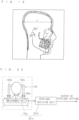
- the X-ray image more specifically a cephalographic image in Fig. 19 is used as the captured image of the head P.
- the cephalographic image is an image previously obtained before the X-ray CT imaging is performed using the X-ray detector 128b and the like of a cephalographic head fixing apparatus 144.
- the physique setting unit 210 includes a skeleton image extractor 212 and a physique decision unit 214 that decides the size of the physique based on an extracted skeleton image.
- the skeleton image extractor 212 performs binarization processing and the like based on the X-ray image and the like to extract a skeleton region of the head or a boundary region of a skeleton.
- the physique decision unit 214 decides a size L of the skeleton in a predetermined operation line or the like based on the extracted skeleton region, the skeleton boundary region, or the like.
- the size of the physique is decided based on the decided size L of the skeleton. For example, a table in which the range of the size of the skeleton is correlated with each of the first physique P(L) or the second physique P(M) is previously stored, and whether the size L corresponds to the first physique P(L) or the second physique P(M) is decided based on the decided size L of the skeleton and the table, and the physique is set according to the decision content.
- the turning control based on the size of the physique as described in the above embodiments in the X-ray generator 126 and the X-ray detector 128 can be performed based on the captured image.
- the captured image may be the panoramic X-ray image or the X-ray image of a part of the teeth.
- the captured image may be an image obtained by a visible light imaging apparatus such as a typical CCD camera.
- the captured image may be an image captured by another X-ray imaging apparatus or a camera. Both the recognition of the X-ray image data and the recognition of the visible light captured image may be performed. In this case, one of results of the recognition of the X-ray image data and the recognition of the visible light captured image may be used to adjust the other result.
- the head fixing apparatus 142 is an example of the subject holder that holds the subject, and includes the chin rest 142a on which the jaw of the head P that is the subject can be placed and supported and the head holder 142b that holds the head P that is the subject from both outer sides of the head P.
- the head holder 142b is provided with a measurement unit 142c that measures the physique of the head P held by the head holder 142b. More specifically, a pair of head holders 142b is openably and closably provided so as to sandwich the left and right portions of the head P.
- the measurement unit 142c measures the opening degree of the pair of head holders 142b. It is assumed that the measurement unit 142c is a variable resistor in which a resistance value changes according to the opening degree of the pair of head holders b, an optical sensor that measures a dimension between the pair of head holders 142b, or the like.
- the measurement unit 142c may be called a physique measure.
- the physique setting unit 251a includes the measurement unit 142c and a physique decision unit 251b.
- the physique decision unit 251b decides the size of the physique based on the measurement signal corresponding to the opening degree. For example, a table in which the range of the opening degree is correlated with each of the first physique P(L) or the second physique P(M) is previously stored, and whether the opening degree corresponds to the first physique P(L) or the second physique P(M) is decided based on the decided opening degree and the table, and the physique is set according to the decision content.
- the turning control based on the size of the physique as described in the above embodiments in the X-ray generator 126 and the X-ray detector 128 can be performed when the head P is fixed to the head fixing apparatus 142 even if the size of the physique is not particularly set.
- a turning support 324 may include an X-ray detector moving mechanism 326 that moves the X-ray detector 128 along the X-ray irradiation direction.
- the X-ray detector moving mechanism 326 is constructed with a moving mechanism including a ball screw mechanism and a motor and a linear actuator such as a linear motor.
- the X-ray detector moving mechanism 326 is incorporated in the turning support 324 to move the X-ray detector 128 along the extending direction of the extending direction of 324, and is displaced between a position DT1 and a position DT2. In the position DT1, the distance in the y-axis direction to the X-ray generator 126 is larger than that in the position DT2.
- the magnification ratio can be adjusted by moving the X-ray detector 128 along the X-ray irradiation direction.
- the motor is an X-ray detector drive motor.
- Fig. 22 illustrates an application example of the X-ray detector moving mechanism 326 in Fig. 21 .
- Fig. 22(a) similarly to Fig. 10 , with respect to the head P2 having the second physique P (M), CT imaging is performed with the position of the mechanical turning axis X1 aligned with the position of the center A of the imaging region R.
- the X-ray detector 128 is disposed at the position DT2, and does not touch with the head P2.
- the turning in Fig. 22(a) is applied to the head P1 having the first physique P(L)
- the X-ray detector 128 is displaced to the position DT1 while the mechanical turning axis X1 is fixed to the position of the center A of the imaging region R, and the turning support 324 is turned while the separation distance to the center A of the imaging region R is increased larger than the position DT2, whereby the contact of the X-ray detector 128 with the head P1 is avoided.
- the X-ray detector 128 may be moved in a far and near direction with respect to the turning axis X1 according to the size of the physique.
- the X-ray detector 128 is turned while located at the position DT1 relatively close to the turning axis X1, whereby the X-ray detector 128 can pass through the imaging region R as close as possible to obtain the clear image.
- the X-ray detector 128 is turned while located at the position DT2 relatively far from the turning axis X1, whereby the touching of the X-ray detector 128 with the head P is avoided.
- the X-ray generator and the X-ray detector have the circular turning orbit.
- the X-ray generator and the X-ray detector may turn while drawing an elliptical trajectory or a trajectory in which the circle and the ellipse are combined.
- the turning trajectories of the X-ray generator and the X-ray detector are changed when the CT imaging is performed on the first physique and the second physique smaller than the first physique.
- the turning trajectories of the X-ray generator and the X-ray detector may be changed according to the sizes of at least three physiques.
- the turning trajectories of the X-ray generator and the X-ray detector may continuously be changed according to the setting of the continuous size of the physique.
- the turning trajectories of the X-ray generator and the X-ray detector may be controlled as in each of the above examples when the sizes of two physiques are assumed.
- a second aspect that is the first aspect is the X-ray CT imaging apparatus in which the circuit switches between drive control in which the supporter is caused to perform the combined motion and drive control in which the supporter is turned while the shaft is fixed to a position of the center of the X-ray CT imaging region, according to the size of the physique of the subject.
- a third aspect that is the first or second aspect is the X-ray CT imaging apparatus in which, according to the size of the physique of the subject, the circuit performs the drive control in which the supporter is caused to perform the combined motion when the set physique of the subject is a first physique, and the circuit performs the drive control in which the supporter is turned while the shaft is fixed to a position of the center of the X-ray CT imaging region when the set physique of the subject is a second physique smaller than the first physique.
- a fourth aspect that is any one of the first to third aspects is the X-ray CT imaging apparatus in which a distance of the shaft to the center of the X-ray CT imaging region is changed according to the set size of the physique of the subject when the combined motion is performed by the supporter.
- a sixth aspect that is any one of the first to fifth aspects is the X-ray CT imaging apparatus in which, when the supporter is caused to perform the combined motion, the crosswise drive motor rotates the shaft about the center of the X-ray CT imaging region in synchronization with the turning of the supporter about the shaft using the turning motor.
- a seventh aspect that is any one of the first to sixth aspects is the X-ray CT imaging apparatus in which the circuit controls adjustment of a regulation amount of the X-ray generated from the X-ray generator according to a distance of the X-ray generator to the center of the X-ray CT imaging region when the X-ray generator and the X-ray detector are turned about the center of the X-ray CT imaging region.
- An eighth aspect that is any one of the first to seventh aspects is the X-ray CT imaging apparatus in which the shaft is disposed along a vertical direction.
- a ninth aspect that is any one of the first to eighth aspects is the X-ray CT imaging apparatus in which the X-ray CT imaging is performed with a jaw region of a head of the subject as the X-ray CT imaging region.
- a tenth aspect that is the ninth aspect is the X-ray CT imaging apparatus in which the X-ray CT imaging is performed with a part of a dental arch on the head of the subject as the X-ray CT imaging region.
- An eleventh aspect that is any one of the first to tenth aspects is the X-ray CT imaging apparatus in which the X-ray generator and the X-ray detector turn around the X-ray CT imaging region to perform the X-ray CT imaging by offset scan while a part of the X-ray CT imaging region is irradiated with the X-ray generated from the X-ray generator at a position where a symmetrical axis of spread of the X-ray deviates from the center of the X-ray CT imaging region.
- a twelfth aspect that is any one of the first to eleventh aspects is the X-ray CT imaging apparatus in which the circuit performs the control in which a distance of the X-ray generator to the center of the X-ray CT imaging region and a distance of the X-ray detector to the center of the X-ray CT imaging region are kept constant while the X-ray CT imaging is performed by irradiating the subject with the X-ray generated from the X-ray generator.
- a thirteenth aspect that is any one of the first to twelfth aspects is the X-ray CT imaging apparatus in which the circuit sets the physique of the subject through reception of an input operation of the physique of the subject.
- a fourteenth aspect that is the thirteenth aspect is the X-ray CT imaging apparatus in which the circuit sets the physique by receiving an input operation to select one of physique sizes of a plurality of selection candidates.
- a fifteenth aspect that is any one of the first to the twelfth aspects is the X-ray CT imaging apparatus in which the circuit automatically recognizes the physique of the subject from at least one of data of a captured image obtained by performing X-ray imaging of the subject or data of a captured image obtained by performing visible light imaging of the subject, and sets the physique of the subject.
- a sixteenth aspect that is any one of the first to twelfth aspects is the X-ray CT imaging apparatus including a subject holder that holds the subject and a physique measure that is provided in the subject holder to measure the physique of the subject held by the subject holder.
- the physique of the subject is set based on a measurement result of the physical measure.
- a seventeenth aspect that is any one of the first to sixteenth aspects is the X-ray CT imaging apparatus in which the supporter includes an X-ray detector drive motor that moves the X-ray detector along an X-ray irradiation direction.
- An eighteenth aspect that is any one of the first to seventeenth aspects is the X-ray CT imaging apparatus in which the crosswise drive motor is controlled such that the X-ray generator and the X-ray detector form a panoramic imaging orbit to perform panoramic X-ray imaging of a dental arch of the subject, and a passage route of the X-ray detector is changed at least in timing of irradiating to a molar region of the dental arch with the X-ray according to the size of the physique of the subject set by the circuit.
Landscapes
- Health & Medical Sciences (AREA)
- Life Sciences & Earth Sciences (AREA)
- Engineering & Computer Science (AREA)
- Medical Informatics (AREA)
- Heart & Thoracic Surgery (AREA)
- Animal Behavior & Ethology (AREA)
- Biophysics (AREA)
- Nuclear Medicine, Radiotherapy & Molecular Imaging (AREA)
- Optics & Photonics (AREA)
- Pathology (AREA)
- Radiology & Medical Imaging (AREA)
- Biomedical Technology (AREA)
- Physics & Mathematics (AREA)
- Molecular Biology (AREA)
- Surgery (AREA)
- High Energy & Nuclear Physics (AREA)
- General Health & Medical Sciences (AREA)
- Public Health (AREA)
- Veterinary Medicine (AREA)
- Dentistry (AREA)
- Oral & Maxillofacial Surgery (AREA)
- Pulmonology (AREA)
- Theoretical Computer Science (AREA)
- Physiology (AREA)
- Apparatus For Radiation Diagnosis (AREA)
Claims (19)
- Appareil (10 ; 110) d'imagerie CT à rayons X comprenant :un support rotatif (20 ; 124 ; 324) qui supporte un générateur de rayons X (22 ; 126) et un détecteur de rayons X (24 ; 128) de sorte que le générateur de rayons X (22 ; 126) et le détecteur de rayons X (24 ; 128) sont opposés l'un à l'autre avec un sujet (P) enserré entre eux ;un mécanisme d'entraînement en rotation (30 ; 130) comportant un mécanisme de rotation (32 ; 132) qui fait tourner ledit support rotatif (20 ; 124 ; 324) autour d'un axe de rotation mécanique (X1) situé entre ledit générateur de rayons X (22 ; 126) et ledit détecteur de rayons X (24 ; 128) et un mécanisme de déplacement d'axe de rotation (38 ; 134) qui déplace ledit axe de rotation mécanique (X1) dans une direction entrecoupant une direction axiale dudit axe de rotation mécanique (X1) ;une unité de réglage de morphologie de sujet (40 ; 151a) qui peut régler une taille d'une morphologie du sujet (P) ; etun contrôleur de rotation (60 ; 151b) qui commande ledit mécanisme de rotation et ledit mécanisme de déplacement d'axe de rotation (38 ; 134),dans lequel lorsque l'imagerie CT est effectuée en irradiant le sujet (P) avec des rayons X générés par ledit générateur de rayons X (22 ; 126), ledit mécanisme de déplacement d'axe de rotation (38 ; 134) déplace ledit axe de rotation mécanique (X1) en synchronisation avec une rotation dudit support rotatif (20 ; 124 ; 324) autour dudit axe de rotation mécanique (X1) à l'aide dudit mécanisme de rotation (32 ; 132), et ledit support rotatif (20 ; 124 ; 324) est amené à effectuer un mouvement combiné, ce qui permet audit générateur de rayons X (22 ; 126) et audit détecteur de rayons X (24 ; 128) de tourner autour d'un centre d'une région d'imagerie CT à rayons X,la commande de position dudit axe de rotation (X1) est effectuée en fonction de la taille de la morphologie du sujet réglée par ladite unité de réglage de morphologie de sujet (40 ; 151a),une distance de séparation est définie comme étant la plus petite parmi une distance entre le centre de ladite région d'imagerie CT à rayons X et ledit générateur de rayons X (126) et une distance entre le centre de ladite région d'imagerie CT à rayons X et ledit détecteur de rayons X (128) ; etlorsque ledit générateur de rayons X (126) et ledit détecteur de rayons X (128) sont tournés autour du centre de ladite région d'imagerie CT à rayons X, une position dudit axe de rotation mécanique (X1) par rapport au centre de ladite région d'imagerie CT à rayons X est commandée de sorte que dans le cas où la morphologie réglée du sujet est une première morphologie, ladite distance de séparation est plus grande que dans le cas où la morphologie réglée du sujet est une deuxième morphologie qui est plus petite que ladite première morphologie selon la taille de la morphologie du sujet réglée par ladite unité de réglage de morphologie de sujet (151a).
- Appareil d'imagerie CT à rayons X selon la revendication 1, dans lequel la commande d'entraînement lors de laquelle ledit support rotatif (124) est amené à effectuer ledit mouvement combiné et la commande d'entraînement lors de laquelle ledit support rotatif (124) est tourné tandis que ledit axe de rotation mécanique (X1) est fixé à une position du centre de ladite région d'imagerie CT à rayons X sont commutées en fonction de la taille de la morphologie du sujet réglée par ladite unité de réglage de morphologie de sujet (151a).
- Appareil d'imagerie CT à rayons X selon la revendication 2, dans lequel, en fonction de la taille de la morphologie du sujet réglée par ladite unité de réglage de morphologie de sujet (151a), la commande d'entraînement lors de laquelle ledit support rotatif (124) est amené à effectuer ledit mouvement combiné est effectuée lorsque la morphologie réglée du sujet est une première morphologie, et la commande d'entraînement lors de laquelle ledit support rotatif (124) est tourné tandis que ledit axe de rotation mécanique est fixé à une position du centre de ladite région d'imagerie CT à rayons X est effectuée lorsque la morphologie réglée du sujet est une deuxième morphologie plus petite que ladite première morphologie.
- Appareil d'imagerie CT à rayons X selon l'une des revendications 1 à 3, dans lequel une distance allant dudit axe de rotation mécanique (X1) au centre de ladite région d'imagerie CT à rayons X est modifiée en fonction de la taille de la morphologie du sujet réglée par ladite unité de réglage de morphologie de sujet (151a) lorsque ledit support rotatif (124) est amené à effectuer ledit mouvement combiné.
- Appareil d'imagerie CT à rayons X selon l'une des revendications 1 à 4, dans lequel, lorsque ledit support rotatif (124) est amené à effectuer ledit mouvement combiné, ledit mécanisme de déplacement d'axe de rotation (134) fait tourner ledit axe de rotation mécanique (X1) autour du centre de ladite région d'imagerie CT à rayons X en synchronisation avec la rotation dudit support rotatif (124) autour dudit axe de rotation mécanique (X1) à l'aide dudit mécanisme de rotation (132).
- Appareil d'imagerie CT à rayons X selon l'une des revendications 1 à 5, comprenant en outre une unité de régulation de rayons X (129) qui ajuste une quantité de régulation des rayons X générés par ledit générateur de rayons X (126) selon une distance dudit générateur de rayons X (126) au centre de ladite région d'imagerie CT à rayons X lorsque ledit générateur de rayons X (126) et ledit détecteur de rayons X (128) sont tournés autour du centre de ladite région d'imagerie CT à rayons X.
- Appareil d'imagerie CT à rayons X selon l'une des revendications 1 à 6, dans lequel ledit axe de rotation mécanique est disposé le long d'une direction verticale.
- Appareil d'imagerie CT à rayons X selon l'une des revendications 1 à 7, dans lequel l'imagerie CT à rayons X est effectuée avec une région de mâchoire d'une tête du sujet en tant que ladite région d'imagerie CT à rayons X.
- Appareil d'imagerie CT à rayons X selon la revendication 8, dans lequel l'imagerie CT à rayons X est effectuée avec une partie d'une arcade dentaire (Ar) de la tête du sujet en tant que ladite région d'imagerie CT à rayons X.
- Appareil d'imagerie CT à rayons X selon l'une des revendications 1 à 9, dans lequel ledit générateur de rayons X (126) et ledit détecteur de rayons X (128) tournent autour de ladite région d'imagerie CT à rayons X pour effectuer l'imagerie CT à rayons X par balayage décalé tandis qu'une partie de ladite région d'imagerie CT à rayons X est irradiée avec lesdits rayons X générés par ledit générateur de rayons X (126) dans une position où un axe de propagation symétrique desdits rayons X s'écarte du centre de ladite région d'imagerie CT à rayons X.
- Appareil d'imagerie CT à rayons X selon l'une des revendications 1 à 10, dans lequel une distance dudit générateur de rayons X (126) au centre de ladite région d'imagerie CT à rayons X et une distance dudit détecteur de rayons X (128) au centre de ladite région d'imagerie CT à rayons X sont maintenues constantes tandis que l'imagerie CT à rayons X est effectuée en irradiant le sujet avec les rayons X générés par ledit générateur de rayons X (126).
- Appareil d'imagerie CT à rayons X selon l'une des revendications 1 à 11, dans lequel ladite unité de réglage de morphologie de sujet (151a) règle la morphologie du sujet en recevant une opération d'entrée de la morphologie du sujet.
- Appareil d'imagerie CT à rayons X selon la revendication 12, dans lequel ladite unité de réglage de morphologie de sujet (151a) règle la morphologie en recevant une opération d'entrée pour sélectionner une des tailles morphologiques d'une pluralité de candidats de sélection.
- Appareil d'imagerie CT à rayons X selon l'une des revendications 1 à 11, dans lequel ladite unité de réglage de morphologie de sujet (210 ; 251a) règle la morphologie du sujet en reconnaissant automatiquement la morphologie du sujet.
- Appareil d'imagerie CT à rayons X selon la revendication 14, dans lequel ladite unité de réglage de morphologie de sujet (210) reconnaît la morphologie du sujet sur la base d'une image capturée du sujet, et règle la morphologie sur la base d'un résultat de reconnaissance.
- Appareil d'imagerie CT à rayons X selon la revendication 14, dans lequel ladite unité de réglage de morphologie de sujet (251a) comporte une unité de mesure (142c) qui est disposée dans un dispositif de maintien (142) qui maintient le sujet, et mesure la morphologie du sujet maintenu par ledit dispositif de maintien (142), et ladite unité de réglage de morphologie de sujet (251a) règle la morphologie du sujet sur la base d'un résultat de mesure de ladite unité de mesure (142c).
- Appareil d'imagerie CT à rayons X selon la revendication 16, dans lequel ladite unité de mesure (142c) mesure un degré d'ouverture d'une pluralité d'éléments (142b) qui maintiennent le sujet.
- Appareil d'imagerie CT à rayons X selon l'une des revendications 1 à 17, dans lequel ledit support rotatif (324) comporte un mécanisme de déplacement de détecteur de rayons X (326) qui déplace ledit détecteur de rayons X (128) le long d'une direction d'irradiation de rayons X.
- Appareil d'imagerie CT à rayons X selon l'une des revendications 1 à 18, dans lequel ledit mécanisme d'entraînement en rotation (130) est commandé de sorte que ledit générateur de rayons X (126) et ledit détecteur de rayons X (128) forment une orbite d'imagerie panoramique pour effectuer une imagerie à rayons X panoramique d'une arcade dentaire du sujet, et une trajectoire de passage dudit détecteur de rayons X (128) est modifiée au moins au moment d'irradiation vers une région molaire de l'arcade dentaire avec les rayons X en fonction de la taille de la morphologie du sujet réglée par l'unité de réglage de morphologie de sujet (151a).
Applications Claiming Priority (2)
| Application Number | Priority Date | Filing Date | Title |
|---|---|---|---|
| JP2017252968 | 2017-12-28 | ||
| PCT/JP2018/048097 WO2019131859A1 (fr) | 2017-12-28 | 2018-12-27 | Dispositif d'imagerie ct par raxons x |
Publications (3)
| Publication Number | Publication Date |
|---|---|
| EP3733074A1 EP3733074A1 (fr) | 2020-11-04 |
| EP3733074A4 EP3733074A4 (fr) | 2021-08-25 |
| EP3733074B1 true EP3733074B1 (fr) | 2025-07-09 |
Family
ID=67063783
Family Applications (1)
| Application Number | Title | Priority Date | Filing Date |
|---|---|---|---|
| EP18895193.3A Active EP3733074B1 (fr) | 2017-12-28 | 2018-12-27 | Dispositif d'imagerie ct par raxons x |
Country Status (6)
| Country | Link |
|---|---|
| US (1) | US11219421B2 (fr) |
| EP (1) | EP3733074B1 (fr) |
| JP (4) | JP7013484B2 (fr) |
| CN (1) | CN111432729B (fr) |
| FI (1) | FI3733074T3 (fr) |
| WO (1) | WO2019131859A1 (fr) |
Families Citing this family (5)
| Publication number | Priority date | Publication date | Assignee | Title |
|---|---|---|---|---|
| KR102043357B1 (ko) * | 2017-10-18 | 2019-11-12 | 오스템임플란트 주식회사 | 영상 확대율 변경 방법 및 장치 |
| JP7086818B2 (ja) * | 2018-10-29 | 2022-06-20 | 富士フイルム株式会社 | 情報処理装置、情報処理方法、及びプログラム |
| JP7468373B2 (ja) * | 2021-01-19 | 2024-04-16 | 株式会社島津製作所 | X線撮影装置 |
| JP7458613B2 (ja) * | 2021-05-11 | 2024-04-01 | 学校法人日本大学 | パノラマx線撮影装置 |
| US12064276B2 (en) * | 2021-05-11 | 2024-08-20 | Nihon University | Panoramic X-ray imaging apparatus |
Family Cites Families (23)
| Publication number | Priority date | Publication date | Assignee | Title |
|---|---|---|---|---|
| JPS60103942A (ja) * | 1983-11-12 | 1985-06-08 | 株式会社モリタ製作所 | 歯科用全顎x線撮影装置 |
| JP3331284B2 (ja) * | 1995-11-06 | 2002-10-07 | 株式会社モリタ製作所 | 医療用x線断層撮影装置 |
| JP4481392B2 (ja) * | 1999-07-27 | 2010-06-16 | 株式会社東芝 | X線診断装置 |
| JP2003029022A (ja) * | 2001-07-19 | 2003-01-29 | Fuji Photo Film Co Ltd | 光学フィルターおよび画像表示装置 |
| JP4149189B2 (ja) * | 2002-04-04 | 2008-09-10 | 株式会社日立メディコ | X線ct装置 |
| JP4724760B2 (ja) * | 2005-04-11 | 2011-07-13 | 株式会社モリタ製作所 | X線撮影装置 |
| JP4632891B2 (ja) | 2005-07-22 | 2011-02-16 | 株式会社モリタ製作所 | X線ct撮影装置およびx線ct撮影方法 |
| WO2009063974A1 (fr) * | 2007-11-16 | 2009-05-22 | J. Morita Manufacturing Corporation | Scanner |
| JP5234764B2 (ja) | 2007-12-11 | 2013-07-10 | 朝日レントゲン工業株式会社 | 医療用x線撮像装置 |
| JP5308739B2 (ja) * | 2008-08-22 | 2013-10-09 | 株式会社モリタ製作所 | X線画像表示方法、及びx線撮影装置 |
| EP2198783B1 (fr) * | 2008-12-19 | 2016-10-12 | Cefla S.C. | Appareil et procédé de balayage numérique à rayons X |
| KR101042935B1 (ko) * | 2009-01-20 | 2011-06-20 | 주식회사바텍 | 경량 x선 촬영장치 |
| KR101034676B1 (ko) * | 2009-03-24 | 2011-06-13 | (주)바텍이우홀딩스 | 이비인후과 및 치과 겸용 x선 촬영장치 |
| WO2011013771A1 (fr) * | 2009-07-30 | 2011-02-03 | 株式会社テレシステムズ | Dispositif de capture d'image par rayonnement et procédé de capture d'image par rayonnement |
| EP2614773B1 (fr) * | 2010-07-13 | 2018-01-03 | Takara Telesystems Corp. | Dispositif d'imagerie de tomogramme à rayons x |
| FI20105934L (fi) * | 2010-09-08 | 2012-03-09 | Palodex Group Oy | Menetelmä ja järjestelmä tietokonetomografiakuvauksen ohjaamiseksi |
| JP5864403B2 (ja) | 2011-11-30 | 2016-02-17 | 株式会社モリタ製作所 | X線ct撮影装置 |
| WO2015026163A1 (fr) | 2013-08-20 | 2015-02-26 | 주식회사바텍 | Dispositif d'imagerie radiographique |
| JP6299010B2 (ja) | 2013-10-25 | 2018-03-28 | 朝日レントゲン工業株式会社 | X線撮影装置及びx線撮影方法 |
| WO2015156603A1 (fr) * | 2014-04-08 | 2015-10-15 | 주식회사 바텍 | Appareil d'imagerie à rayons x détectant des mouvements d'un sujet d'imagerie |
| JP6483968B2 (ja) * | 2014-07-11 | 2019-03-13 | 株式会社吉田製作所 | 歯科用x線撮影装置 |
| JP6322164B2 (ja) * | 2015-07-21 | 2018-05-09 | 株式会社モリタ製作所 | 医療用x線撮影装置 |
| JP6768473B2 (ja) * | 2016-01-14 | 2020-10-14 | キヤノンメディカルシステムズ株式会社 | 医用画像診断装置 |
-
2018
- 2018-12-27 CN CN201880078116.3A patent/CN111432729B/zh active Active
- 2018-12-27 FI FIEP18895193.3T patent/FI3733074T3/fi active
- 2018-12-27 EP EP18895193.3A patent/EP3733074B1/fr active Active
- 2018-12-27 WO PCT/JP2018/048097 patent/WO2019131859A1/fr not_active Ceased
- 2018-12-27 JP JP2019562152A patent/JP7013484B2/ja not_active Expired - Fee Related
-
2020
- 2020-06-23 US US16/909,985 patent/US11219421B2/en active Active
-
2022
- 2022-01-19 JP JP2022006306A patent/JP2022046806A/ja active Pending
-
2023
- 2023-08-28 JP JP2023138013A patent/JP7489533B2/ja active Active
-
2024
- 2024-04-04 JP JP2024060711A patent/JP7664448B2/ja active Active
Also Published As
| Publication number | Publication date |
|---|---|
| JP2024074925A (ja) | 2024-05-31 |
| JP7013484B2 (ja) | 2022-01-31 |
| JP7489533B2 (ja) | 2024-05-23 |
| EP3733074A4 (fr) | 2021-08-25 |
| JP7664448B2 (ja) | 2025-04-17 |
| WO2019131859A1 (fr) | 2019-07-04 |
| FI3733074T3 (fi) | 2025-08-26 |
| US11219421B2 (en) | 2022-01-11 |
| EP3733074A1 (fr) | 2020-11-04 |
| JPWO2019131859A1 (ja) | 2020-11-19 |
| JP2022046806A (ja) | 2022-03-23 |
| CN111432729A (zh) | 2020-07-17 |
| CN111432729B (zh) | 2023-09-05 |
| US20200315555A1 (en) | 2020-10-08 |
| JP2023156527A (ja) | 2023-10-24 |
Similar Documents
| Publication | Publication Date | Title |
|---|---|---|
| EP3733074B1 (fr) | Dispositif d'imagerie ct par raxons x | |
| EP3773217B1 (fr) | Alignement d'un dispositif d'imagerie médicale à rayons x à l'aide du plan de francfort | |
| JP6959375B2 (ja) | 医療画像診断のためのx線撮影装置 | |
| US9795347B2 (en) | Scanning system for three-dimensional imaging | |
| EP3653125B1 (fr) | Étalonnage d'un dispositif d'imagerie médicale à rayons x pour l'imagerie céphalométrique | |
| EP3578105B1 (fr) | Appareil d'imagerie ct à rayons x | |
| EP3785637B1 (fr) | Dispositif d'imagerie ct à rayons x et procédé de commande destiné à un dispositif d'imagerie ct à rayons x | |
| JP6903608B2 (ja) | X線ct撮影装置 | |
| JP2005111152A (ja) | 外科用x線装置 | |
| JP2025040839A (ja) | X線透視撮影装置 |
Legal Events
| Date | Code | Title | Description |
|---|---|---|---|
| STAA | Information on the status of an ep patent application or granted ep patent |
Free format text: STATUS: THE INTERNATIONAL PUBLICATION HAS BEEN MADE |
|
| PUAI | Public reference made under article 153(3) epc to a published international application that has entered the european phase |
Free format text: ORIGINAL CODE: 0009012 |
|
| STAA | Information on the status of an ep patent application or granted ep patent |
Free format text: STATUS: REQUEST FOR EXAMINATION WAS MADE |
|
| 17P | Request for examination filed |
Effective date: 20200618 |
|
| AK | Designated contracting states |
Kind code of ref document: A1 Designated state(s): AL AT BE BG CH CY CZ DE DK EE ES FI FR GB GR HR HU IE IS IT LI LT LU LV MC MK MT NL NO PL PT RO RS SE SI SK SM TR |
|
| AX | Request for extension of the european patent |
Extension state: BA ME |
|
| DAV | Request for validation of the european patent (deleted) | ||
| DAX | Request for extension of the european patent (deleted) | ||
| A4 | Supplementary search report drawn up and despatched |
Effective date: 20210728 |
|
| RIC1 | Information provided on ipc code assigned before grant |
Ipc: A61B 6/14 20060101AFI20210722BHEP Ipc: A61B 6/00 20060101ALI20210722BHEP Ipc: A61B 6/03 20060101ALI20210722BHEP Ipc: A61B 6/02 20060101ALI20210722BHEP |
|
| STAA | Information on the status of an ep patent application or granted ep patent |
Free format text: STATUS: EXAMINATION IS IN PROGRESS |
|
| 17Q | First examination report despatched |
Effective date: 20221214 |
|
| REG | Reference to a national code |
Ref country code: DE Free format text: PREVIOUS MAIN CLASS: A61B0006140000 Ref country code: DE Ref legal event code: R079 Ref document number: 602018083508 Country of ref document: DE Free format text: PREVIOUS MAIN CLASS: A61B0006140000 Ipc: A61B0006000000 |
|
| GRAP | Despatch of communication of intention to grant a patent |
Free format text: ORIGINAL CODE: EPIDOSNIGR1 |
|
| STAA | Information on the status of an ep patent application or granted ep patent |
Free format text: STATUS: GRANT OF PATENT IS INTENDED |
|
| RIC1 | Information provided on ipc code assigned before grant |
Ipc: A61B 6/51 20240101ALI20250130BHEP Ipc: A61B 6/58 20240101ALI20250130BHEP Ipc: A61B 6/50 20240101ALI20250130BHEP Ipc: A61B 6/03 20060101ALI20250130BHEP Ipc: A61B 6/02 20060101ALI20250130BHEP Ipc: A61B 6/00 20060101AFI20250130BHEP |
|
| INTG | Intention to grant announced |
Effective date: 20250211 |
|
| GRAS | Grant fee paid |
Free format text: ORIGINAL CODE: EPIDOSNIGR3 |
|
| GRAA | (expected) grant |
Free format text: ORIGINAL CODE: 0009210 |
|
| STAA | Information on the status of an ep patent application or granted ep patent |
Free format text: STATUS: THE PATENT HAS BEEN GRANTED |
|
| P01 | Opt-out of the competence of the unified patent court (upc) registered |
Free format text: CASE NUMBER: APP_22711/2025 Effective date: 20250513 |
|
| AK | Designated contracting states |
Kind code of ref document: B1 Designated state(s): AL AT BE BG CH CY CZ DE DK EE ES FI FR GB GR HR HU IE IS IT LI LT LU LV MC MK MT NL NO PL PT RO RS SE SI SK SM TR |
|
| REG | Reference to a national code |
Ref country code: GB Ref legal event code: FG4D |
|
| REG | Reference to a national code |
Ref country code: CH Ref legal event code: EP |
|
| REG | Reference to a national code |
Ref country code: IE Ref legal event code: FG4D |
|
| REG | Reference to a national code |
Ref country code: DE Ref legal event code: R096 Ref document number: 602018083508 Country of ref document: DE |
|
| REG | Reference to a national code |
Ref country code: FI Ref legal event code: FGE |
|
| REG | Reference to a national code |
Ref country code: NL Ref legal event code: MP Effective date: 20250709 |
|
| PG25 | Lapsed in a contracting state [announced via postgrant information from national office to epo] |
Ref country code: PT Free format text: LAPSE BECAUSE OF FAILURE TO SUBMIT A TRANSLATION OF THE DESCRIPTION OR TO PAY THE FEE WITHIN THE PRESCRIBED TIME-LIMIT Effective date: 20251110 |
|
| PG25 | Lapsed in a contracting state [announced via postgrant information from national office to epo] |
Ref country code: NL Free format text: LAPSE BECAUSE OF FAILURE TO SUBMIT A TRANSLATION OF THE DESCRIPTION OR TO PAY THE FEE WITHIN THE PRESCRIBED TIME-LIMIT Effective date: 20250709 |
|
| REG | Reference to a national code |
Ref country code: AT Ref legal event code: MK05 Ref document number: 1811045 Country of ref document: AT Kind code of ref document: T Effective date: 20250709 |
|
| PG25 | Lapsed in a contracting state [announced via postgrant information from national office to epo] |
Ref country code: IS Free format text: LAPSE BECAUSE OF FAILURE TO SUBMIT A TRANSLATION OF THE DESCRIPTION OR TO PAY THE FEE WITHIN THE PRESCRIBED TIME-LIMIT Effective date: 20251109 |
|
| PG25 | Lapsed in a contracting state [announced via postgrant information from national office to epo] |
Ref country code: NO Free format text: LAPSE BECAUSE OF FAILURE TO SUBMIT A TRANSLATION OF THE DESCRIPTION OR TO PAY THE FEE WITHIN THE PRESCRIBED TIME-LIMIT Effective date: 20251009 |
|
| REG | Reference to a national code |
Ref country code: LT Ref legal event code: MG9D |
|
| PG25 | Lapsed in a contracting state [announced via postgrant information from national office to epo] |
Ref country code: AT Free format text: LAPSE BECAUSE OF FAILURE TO SUBMIT A TRANSLATION OF THE DESCRIPTION OR TO PAY THE FEE WITHIN THE PRESCRIBED TIME-LIMIT Effective date: 20250709 |
|
| PGFP | Annual fee paid to national office [announced via postgrant information from national office to epo] |
Ref country code: FI Payment date: 20251216 Year of fee payment: 8 |
|
| PG25 | Lapsed in a contracting state [announced via postgrant information from national office to epo] |
Ref country code: HR Free format text: LAPSE BECAUSE OF FAILURE TO SUBMIT A TRANSLATION OF THE DESCRIPTION OR TO PAY THE FEE WITHIN THE PRESCRIBED TIME-LIMIT Effective date: 20250709 |
|
| PGFP | Annual fee paid to national office [announced via postgrant information from national office to epo] |
Ref country code: FR Payment date: 20251217 Year of fee payment: 8 |
|
| PG25 | Lapsed in a contracting state [announced via postgrant information from national office to epo] |
Ref country code: GR Free format text: LAPSE BECAUSE OF FAILURE TO SUBMIT A TRANSLATION OF THE DESCRIPTION OR TO PAY THE FEE WITHIN THE PRESCRIBED TIME-LIMIT Effective date: 20251010 |
|
| PG25 | Lapsed in a contracting state [announced via postgrant information from national office to epo] |
Ref country code: SE Free format text: LAPSE BECAUSE OF FAILURE TO SUBMIT A TRANSLATION OF THE DESCRIPTION OR TO PAY THE FEE WITHIN THE PRESCRIBED TIME-LIMIT Effective date: 20250709 |
|
| PG25 | Lapsed in a contracting state [announced via postgrant information from national office to epo] |
Ref country code: LV Free format text: LAPSE BECAUSE OF FAILURE TO SUBMIT A TRANSLATION OF THE DESCRIPTION OR TO PAY THE FEE WITHIN THE PRESCRIBED TIME-LIMIT Effective date: 20250709 |
|
| PG25 | Lapsed in a contracting state [announced via postgrant information from national office to epo] |
Ref country code: BG Free format text: LAPSE BECAUSE OF FAILURE TO SUBMIT A TRANSLATION OF THE DESCRIPTION OR TO PAY THE FEE WITHIN THE PRESCRIBED TIME-LIMIT Effective date: 20250709 Ref country code: PL Free format text: LAPSE BECAUSE OF FAILURE TO SUBMIT A TRANSLATION OF THE DESCRIPTION OR TO PAY THE FEE WITHIN THE PRESCRIBED TIME-LIMIT Effective date: 20250709 |
|
| PG25 | Lapsed in a contracting state [announced via postgrant information from national office to epo] |
Ref country code: RS Free format text: LAPSE BECAUSE OF FAILURE TO SUBMIT A TRANSLATION OF THE DESCRIPTION OR TO PAY THE FEE WITHIN THE PRESCRIBED TIME-LIMIT Effective date: 20251009 |
|
| PG25 | Lapsed in a contracting state [announced via postgrant information from national office to epo] |
Ref country code: ES Free format text: LAPSE BECAUSE OF FAILURE TO SUBMIT A TRANSLATION OF THE DESCRIPTION OR TO PAY THE FEE WITHIN THE PRESCRIBED TIME-LIMIT Effective date: 20250709 |
|
| PG25 | Lapsed in a contracting state [announced via postgrant information from national office to epo] |
Ref country code: RO Free format text: LAPSE BECAUSE OF FAILURE TO SUBMIT A TRANSLATION OF THE DESCRIPTION OR TO PAY THE FEE WITHIN THE PRESCRIBED TIME-LIMIT Effective date: 20250709 |
|
| PG25 | Lapsed in a contracting state [announced via postgrant information from national office to epo] |
Ref country code: SM Free format text: LAPSE BECAUSE OF FAILURE TO SUBMIT A TRANSLATION OF THE DESCRIPTION OR TO PAY THE FEE WITHIN THE PRESCRIBED TIME-LIMIT Effective date: 20250709 |
|
| PG25 | Lapsed in a contracting state [announced via postgrant information from national office to epo] |
Ref country code: DK Free format text: LAPSE BECAUSE OF FAILURE TO SUBMIT A TRANSLATION OF THE DESCRIPTION OR TO PAY THE FEE WITHIN THE PRESCRIBED TIME-LIMIT Effective date: 20250709 |
|
| PGFP | Annual fee paid to national office [announced via postgrant information from national office to epo] |
Ref country code: DE Payment date: 20251215 Year of fee payment: 8 |
|
| PG25 | Lapsed in a contracting state [announced via postgrant information from national office to epo] |
Ref country code: IT Free format text: LAPSE BECAUSE OF FAILURE TO SUBMIT A TRANSLATION OF THE DESCRIPTION OR TO PAY THE FEE WITHIN THE PRESCRIBED TIME-LIMIT Effective date: 20250709 |