EP3733096B1 - Système de positionnement de guide de coupe osseuse - Google Patents
Système de positionnement de guide de coupe osseuse Download PDFInfo
- Publication number
- EP3733096B1 EP3733096B1 EP20157613.9A EP20157613A EP3733096B1 EP 3733096 B1 EP3733096 B1 EP 3733096B1 EP 20157613 A EP20157613 A EP 20157613A EP 3733096 B1 EP3733096 B1 EP 3733096B1
- Authority
- EP
- European Patent Office
- Prior art keywords
- coupling
- guide
- bone
- target bone
- landing
- Prior art date
- Legal status (The legal status is an assumption and is not a legal conclusion. Google has not performed a legal analysis and makes no representation as to the accuracy of the status listed.)
- Active
Links
Images



Classifications
-
- A—HUMAN NECESSITIES
- A61—MEDICAL OR VETERINARY SCIENCE; HYGIENE
- A61B—DIAGNOSIS; SURGERY; IDENTIFICATION
- A61B34/00—Computer-aided surgery; Manipulators or robots specially adapted for use in surgery
- A61B34/10—Computer-aided planning, simulation or modelling of surgical operations
-
- A—HUMAN NECESSITIES
- A61—MEDICAL OR VETERINARY SCIENCE; HYGIENE
- A61B—DIAGNOSIS; SURGERY; IDENTIFICATION
- A61B17/00—Surgical instruments, devices or methods
- A61B17/14—Surgical saws
- A61B17/15—Guides therefor
-
- A—HUMAN NECESSITIES
- A61—MEDICAL OR VETERINARY SCIENCE; HYGIENE
- A61B—DIAGNOSIS; SURGERY; IDENTIFICATION
- A61B17/00—Surgical instruments, devices or methods
- A61B17/16—Instruments for performing osteoclasis; Drills or chisels for bones; Trepans
- A61B17/17—Guides or aligning means for drills, mills, pins or wires
-
- A—HUMAN NECESSITIES
- A61—MEDICAL OR VETERINARY SCIENCE; HYGIENE
- A61B—DIAGNOSIS; SURGERY; IDENTIFICATION
- A61B34/00—Computer-aided surgery; Manipulators or robots specially adapted for use in surgery
- A61B34/20—Surgical navigation systems; Devices for tracking or guiding surgical instruments, e.g. for frameless stereotaxis
-
- G—PHYSICS
- G16—INFORMATION AND COMMUNICATION TECHNOLOGY [ICT] SPECIALLY ADAPTED FOR SPECIFIC APPLICATION FIELDS
- G16H—HEALTHCARE INFORMATICS, i.e. INFORMATION AND COMMUNICATION TECHNOLOGY [ICT] SPECIALLY ADAPTED FOR THE HANDLING OR PROCESSING OF MEDICAL OR HEALTHCARE DATA
- G16H20/00—ICT specially adapted for therapies or health-improving plans, e.g. for handling prescriptions, for steering therapy or for monitoring patient compliance
- G16H20/40—ICT specially adapted for therapies or health-improving plans, e.g. for handling prescriptions, for steering therapy or for monitoring patient compliance relating to mechanical, radiation or invasive therapies, e.g. surgery, laser therapy, dialysis or acupuncture
-
- G—PHYSICS
- G16—INFORMATION AND COMMUNICATION TECHNOLOGY [ICT] SPECIALLY ADAPTED FOR SPECIFIC APPLICATION FIELDS
- G16H—HEALTHCARE INFORMATICS, i.e. INFORMATION AND COMMUNICATION TECHNOLOGY [ICT] SPECIALLY ADAPTED FOR THE HANDLING OR PROCESSING OF MEDICAL OR HEALTHCARE DATA
- G16H40/00—ICT specially adapted for the management or administration of healthcare resources or facilities; ICT specially adapted for the management or operation of medical equipment or devices
- G16H40/40—ICT specially adapted for the management or administration of healthcare resources or facilities; ICT specially adapted for the management or operation of medical equipment or devices for the management of medical equipment or devices, e.g. scheduling maintenance or upgrades
-
- G—PHYSICS
- G16—INFORMATION AND COMMUNICATION TECHNOLOGY [ICT] SPECIALLY ADAPTED FOR SPECIFIC APPLICATION FIELDS
- G16H—HEALTHCARE INFORMATICS, i.e. INFORMATION AND COMMUNICATION TECHNOLOGY [ICT] SPECIALLY ADAPTED FOR THE HANDLING OR PROCESSING OF MEDICAL OR HEALTHCARE DATA
- G16H40/00—ICT specially adapted for the management or administration of healthcare resources or facilities; ICT specially adapted for the management or operation of medical equipment or devices
- G16H40/60—ICT specially adapted for the management or administration of healthcare resources or facilities; ICT specially adapted for the management or operation of medical equipment or devices for the operation of medical equipment or devices
- G16H40/63—ICT specially adapted for the management or administration of healthcare resources or facilities; ICT specially adapted for the management or operation of medical equipment or devices for the operation of medical equipment or devices for local operation
-
- G—PHYSICS
- G16—INFORMATION AND COMMUNICATION TECHNOLOGY [ICT] SPECIALLY ADAPTED FOR SPECIFIC APPLICATION FIELDS
- G16H—HEALTHCARE INFORMATICS, i.e. INFORMATION AND COMMUNICATION TECHNOLOGY [ICT] SPECIALLY ADAPTED FOR THE HANDLING OR PROCESSING OF MEDICAL OR HEALTHCARE DATA
- G16H50/00—ICT specially adapted for medical diagnosis, medical simulation or medical data mining; ICT specially adapted for detecting, monitoring or modelling epidemics or pandemics
- G16H50/50—ICT specially adapted for medical diagnosis, medical simulation or medical data mining; ICT specially adapted for detecting, monitoring or modelling epidemics or pandemics for simulation or modelling of medical disorders
-
- A—HUMAN NECESSITIES
- A61—MEDICAL OR VETERINARY SCIENCE; HYGIENE
- A61B—DIAGNOSIS; SURGERY; IDENTIFICATION
- A61B17/00—Surgical instruments, devices or methods
- A61B17/14—Surgical saws
- A61B17/15—Guides therefor
- A61B17/154—Guides therefor for preparing bone for knee prosthesis
- A61B17/155—Cutting femur
-
- A—HUMAN NECESSITIES
- A61—MEDICAL OR VETERINARY SCIENCE; HYGIENE
- A61B—DIAGNOSIS; SURGERY; IDENTIFICATION
- A61B17/00—Surgical instruments, devices or methods
- A61B17/16—Instruments for performing osteoclasis; Drills or chisels for bones; Trepans
-
- A—HUMAN NECESSITIES
- A61—MEDICAL OR VETERINARY SCIENCE; HYGIENE
- A61B—DIAGNOSIS; SURGERY; IDENTIFICATION
- A61B34/00—Computer-aided surgery; Manipulators or robots specially adapted for use in surgery
- A61B34/10—Computer-aided planning, simulation or modelling of surgical operations
- A61B2034/101—Computer-aided simulation of surgical operations
- A61B2034/105—Modelling of the patient, e.g. for ligaments or bones
-
- A—HUMAN NECESSITIES
- A61—MEDICAL OR VETERINARY SCIENCE; HYGIENE
- A61B—DIAGNOSIS; SURGERY; IDENTIFICATION
- A61B34/00—Computer-aided surgery; Manipulators or robots specially adapted for use in surgery
- A61B34/10—Computer-aided planning, simulation or modelling of surgical operations
- A61B2034/107—Visualisation of planned trajectories or target regions
-
- A—HUMAN NECESSITIES
- A61—MEDICAL OR VETERINARY SCIENCE; HYGIENE
- A61B—DIAGNOSIS; SURGERY; IDENTIFICATION
- A61B34/00—Computer-aided surgery; Manipulators or robots specially adapted for use in surgery
- A61B34/10—Computer-aided planning, simulation or modelling of surgical operations
- A61B2034/108—Computer aided selection or customisation of medical implants or cutting guides
-
- A—HUMAN NECESSITIES
- A61—MEDICAL OR VETERINARY SCIENCE; HYGIENE
- A61B—DIAGNOSIS; SURGERY; IDENTIFICATION
- A61B34/00—Computer-aided surgery; Manipulators or robots specially adapted for use in surgery
- A61B34/20—Surgical navigation systems; Devices for tracking or guiding surgical instruments, e.g. for frameless stereotaxis
- A61B2034/2074—Interface software
Definitions
- This document relates generally to an orthopedic surgical device for use in operating on a target bone.
- a cut guide can be used in an orthopedic surgery to assist a surgeon in cutting or modifying some portions of a target bone.
- a cut guide can be temporarily attached to the target bone such as a femur or a tibia.
- An orthopedic surgical cutting tool can be used together with the cut guide to allow the surgeon to selectively cut portions of the ends of the target bone and replaced with endoprosthetic implants.
- Positioning a cut guide for use in preparing the target bone can be a time consuming and complicated process, which is critical to positive outcomes for the patient.
- US 2011/245835 Al describes patient-specific surgical instruments, and in particular cutting guides, and methods of use and manufacture.
- US 2010/191244 A1 describes a surgical template system for use in working on a bone.
- WO 2011/106399 Al describes a number of orthopaedic surgical instruments; and a method, apparatus, and system for fabricating such instruments.
- US 2010/100192 Al describes methods and apparatus for knee arthroplasty, including implants, positioning and alignment guides, cutting guides, cutting tools and techniques for the femur and/or tibia.
- US 2009/082774 Al describes a surgical cutting guide that is adapted to receive a cutting instrument during a surgical procedure.
- a cut guide can be crucial to the outcome of orthopedic surgeries such as prosthesis implantation.
- portions of the articulation tissues of a target bone such as acetabulum, a femur, or a tibia, need to resected and altered to allow an implant to be securely positioned onto the target bone.
- a cut guide positioned on the target bone can be used to guide a cutting saw to resect the target bone to a desired shape. Proper positioning of the cut guide on the bone can improve the accuracy of the bone resection and reduce procedure time.
- Positioning of cut guide onto a target bone usually requires a surgeon to mentally map and compare the shape, orientation, and relative positions of the implant and the target bones.
- Computer-aided tools can be used to assist the surgeon in positioning the cut guide relative to the bone.
- the computer-assistance is limited to intraoperative navigation of traditional cutting jigs. The designs of these jigs, the tools to align them, and the implants that they support are all compromises meant to serve a general population.
- Various embodiments described herein can help improve the efficacy and the reliability in osteoplasty planning, such as resecting portions of bone surface for cut guide positioning.
- the methods and devices described herein can also be applicable to planning surgery of pathological bones under various other conditions.
- the present invention is defined in claim 1 while preferred embodiments are set forth in the dependent claims. Associated methods are also described herein to aid understanding the invention. These methods do not form part of the claimed invention.
- FIG. 1A-D illustrate an embodiment of an orthopedic surgical device for use in operating on a target bone 300.
- the orthopedic surgical device comprises a cut guide 100, illustrated in FIG. 1B , configured to be adjustably positioned onto or otherwise conform to the target bone 300 as illustrated in FIG. 1A .
- the cut guide 100 includes a guide body 110 forming the cut guide 100, and a plurality of landing members such as 130A-B.
- the guide body 110 forms the supporting structure of the cut guide 100, and can be made of metal, alloy, polymer, or other rigid dimensionally stable materials.
- the guide body 110 includes one or more guide members 120A-D.
- Each guide member can be sized, shaped or otherwise configured to constrain and guide a cutting tool (not shown) along a respective cutting trajectory determined by the guide member.
- the guide members 120A-D can have slotted structures sized to securely receive and constrain the cutting tool, and allow the cutting tool to move freely within the respective slotted structure.
- the guide members 120A-D can have openings on an exterior of the guide body 110. The openings can be sized to facilitate placement of the cutting tool into one or more of the guide members 120A-D, and connection between a portion of the cutting tool and an external driving device such as a robotic arm for manipulating the cutting tool within the guide members.
- Each of the landing members 130A-B on the cut guide 100 can include a respective coupling feature.
- the coupling features can be configured to removably couple to the target bone 300 at two or more landing sites on the target bone 300.
- the landing sites define desired locations on the target bone onto which the cut guide can be securely positioned.
- the model receiver module 210 can be configured to receive a generic post-coupling bone model (M coupling ).
- the model M coupling can include a data set representing a bone having an anatomical origin comparable to the target bone to be altered by the system 200.
- the data set can include shape or appearance information of the bone.
- the model M coupling can be in a form of a parametric model, a statistical model, a shape-based model such as a statistical shape model, or a volumetric model.
- the model M coupling can also be based on physical properties of the normal bone, such as an elastic model, a geometric spine model, or a finite element model.
- the model M coupling can include representations of two or more coupling receptacles each sized, shaped or otherwise configured to receive and secure the respective coupling feature on the cut guide 100, such as protruding portions 131A-B.
- the coupling receptacle representation can include indications of locations, sizes, shapes, volume, or other geometric or morphological descriptors.
- the model M coupling can be derived from a plurality of images of post-coupling bones (i.e., bones with the coupling receptacles created) having comparable anatomical origin from a group of subjects.
- the coupling receptacle representation includes computer-simulated graphs or annotative markings that identify the boundaries of the recessed portions of the coupling receptacle.
- the sizes, shapes, volume, or other geometric or morphological descriptors of the coupling receptacle representations can be determined using the size, shape, volume, or other geometric or morphological descriptors of the respective protruding portion (such as 131A-B) of the landing members on the cut guide 100.
- the computer-simulated coupling receptacle representation can be separately generated and then added to a coupler-free normal bone model to create the generic post-coupling bone model M coupling .
- the model M coupling can be generated using a system external to the system 200, and stored in a machine-readable medium such as a memory device.
- the model receiver module 210 can retrieve model M coupling from the memory device upon receiving a command from an end-user.
- the system 200 can include a post-coupling bone model generator that can create a generic post-coupling bone model (M coupling ) using shape data or appearance data.
- the shape data may include geometric characteristics of a bone such as landmarks, surfaces, boundaries of three-dimensional images objections.
- the appearance data may include both geometric characteristics and intensity information of a bone.
- the shape or appearance data can be constructed from a plurality of medical images of the normal bones of comparable anatomical origin from a group of subjects.
- the medical images can include two-dimensional (2D) or three-dimensional (3D) images, including an X-ray, an ultrasound image, a computed tomography (CT) scan, a magnetic resonance (MR) image, a positron emission tomography (PET) image, or a single-photon emission computed tomography (SPECT) image, or an arthrogram.
- the shape or appearance data can be constructed from a plurality of point clouds acquired from bones having comparable anatomical origin from a group of subjects using a coordinated measuring system such as one or more tracking probes.
- the input interface 220 can be configured to receive a target bone representation (X pre-coupling ) from a patient database.
- the target bone representation (X pre-coupling ) can be generated by an imaging system or other image acquisition module within or external to the system 200, and received by the system 200 via the input interface 220.
- Examples of target bone can include an acetabulum, a proximal or distal extremity of a femur, a proximal or distal extremity of a tibia, or other bones in a body.
- the representation X pre-coupling can be in a form of a medical image, a point cloud, a parametric model, or other morphological description of the target bone.
- the representation X pre-coupling includes a data set representing the shape, appearance, or other morphological characteristics of the target bone.
- the representation X pre-coupling includes two or more landing site representations on a surface of the target bone where two or more coupling receptacles can be created.
- the navigation-based guide coupling preparation system 230 can include a cut guide positioning planning module 231 configured to generate a plan for positioning the cut guide onto or conforming to the target bone.
- the cut guide positioning planning module 231 can include a registration module 232 and a positioning plan formation module 233.
- the registration module 232 can take as an input the generic post-coupling bone model M coupling and the target bone representation X pre-coupling , register M coupling to X pre-coupling , and create a registered post-coupling bone model M* coupling .
- FIG. 2B is a block diagram illustrating an embodiment of the registration module 232.
- the registration module 232 can include a segmentation module 271, a model transformation module 272, a matching module 273, and an alignment module 274.
- the segmentation module 271 can be configured to partition the model M coupling and the target bone representation X pre-coupling each into a plurality of segments. Each segment can represent a specified anatomical structure.
- a label can be assigned to each of the segments, such that the segments with the same label share specified characteristics such as a shape, anatomical structure, or intensity.
- the segmentation module 271 can differentiate a portion of M coupling containing the coupling receptacle representation from a different portion of the M coupling free of coupling receptacle representation, and identify from the segments of the M coupling a registration area free of coupling receptacles.
- the model transformation module 272 can transform the generic post-coupling bone model M coupling to create the registered post-coupling model M* coupling using a comparison between the coupler-free segment of M coupling and the corresponding segments of the X pre-coupling .
- the transformation can include linear or nonlinear operations such as scaling, rotation, translation, expansion, dilation, or other affine transformation.
- the transformation can include rigid transformations that preserve the distance (such as translation, rotation, and reflection) or non-rigid transformations such as stretching, shrinking, or model-based transformations such as radial basis functions, splines, or finite element model.
- the registration module 232 can employ both the rigid transformation to bring the M coupling in global alignment with the size and orientation of the target bone representation X pre-coupling , and the non-rigid transformation to reduce the local geometric discrepancies by aligning the M coupling with the X pre-coupling .
- the model M* coupling contains desired size, shape, volume, and other geometric or morphological descriptors of the coupling receptacles on the target bone.
- the matching module 273 can match one or more segments of the registered post-coupling model M* coupling to the corresponding registration area of the X pre-coupling .
- the alignment module 274 can align the remaining segments of M* coupling with the remaining segments of the target bone representation X pre-coupling based at least on the matching. This produces an alignment between the registered post-coupling model M* coupling and the target bone representation X pre- coupling.
- the positioning plan formation module 233 can use the comparison between the registered post-coupling model M* coupling and the target bone representation X pre-coupling to determine the two or more landing sites on the target bone for respectively creating the coupling receptacles, and determining sizes, shapes, volume, or other geometric or morphological descriptors of the coupling receptacles.
- the comparison can be performed on all or selected segments (such as the segments containing the coupling receptacles) of the registered post-coupling model M* coupling and the target bone representation X pre-coupling .
- the system 230 can further include a coupling receptacle preparation tool 235.
- the coupling receptacle preparation tool 235 can be a temporary tool used for producing the two or more coupling receptacles on the landing site of the target bone according to the positioning plan generated by the positioning plan formation module 233.
- the coupling receptacle preparation tool 235 can be operated manually by an end-user, or automatically by a computer-controlled system. An example of such a cutting tool can be found in Brisson et al., U.S. Pat. No. 6,757,582 , entitled "Methods and systems to control a shaping tool".
- the coupling receptacle preparation tool 235 is operated to progressively create the coupling receptacles using a comparison between the registered post-coupling model M* coupling and a perioperative target bone representation X peri-coupling .
- the input interface 220 can receive the perioperative target bone representation X peri-coupling including coupling receptacle representations during the process of creating the coupling receptacles.
- the perioperative representation X peri-coupling can be updated in real-time such as using a camera and a monitoring device, or upon receiving a user command.
- the cut guide positioning planning module 231 can compute a similarity metric between the desired coupling receptacles on the registered post-coupling model M* coupling and the corresponding perioperative coupling receptacles on the perioperative target bone representation X peri-coupling .
- Examples of the similarity metric can include L1 norm, L2 norm (Euclidian distance), infinite norm, or other norm in the normed vector space.
- the similarity metric can also include correlation coefficient, mutual information, or ratio image uniformity.
- the communication interface 240 coupled to the navigation-based guide coupling preparation system 230, can be configured to present information of the model and the target bone in audio, visual, or other multi-media formats to assist the surgeon during the process of creating and evaluating a surgical plan.
- the information presented can include the generic post-coupling bone model M coupling , the registered post-coupling model M* coupling , the target bone representation X pre-coupling , the landing sites representation and the coupling receptacles on the target bone, the perioperative target bone representation X peri-coupling , the similarity metric between the desired coupling receptacles and the perioperative coupling receptacles, and the indication of the completion of the coupling receptacle preparation.
- the communication interface 240 can include a display module such as a monitor for displaying dialog, text, 2D or 3D graphs, or animations of the bone models and the target bone representation, among other things.
- the graphs or animation can include color-codes, annotations, or other visual enhancements on the perioperative coupling receptacles.
- the communication interface 240 can also include a user input device configured to receive user input to accept or modify the surgical plan generated by the surgical planning module 130.
- the coupling receptacles 331A-B can each include a respective recessed portion sized, shaped or otherwise configured to receive and secure a protruding portion of the coupling feature on the landing members of a cut guide 100, such as the protruding portions 131A-B.
- the landing sites 330A-B, as well as the sizes, shapes, volume, or other geometric or morphological descriptors of the coupling receptacles, can be determined by the cut guide positioning planning module 231. In an example, the size and shape of the coupling receptacles can be determined based on the size and shape of the protruding portions 131A-B of the landing members.
- the recessed portion of the coupling receptacles 331A-B can be in a shape of a cylinder, a cube, a rectangular prism, a triangular prism, a pyramid, a cone, or other three-dimensional shapes.
- the size and shape of the coupling receptacles can also be determined based on the location of the landing sites, or based on the anatomical, mechanical, and physical properties of the bone and soft tissues at the landing sites.
- FIGS. 4A-B are block diagrams that illustrate an example of an orthopedic surgical system 400 for operating on a target bone.
- the system 400 which is outside the scope of the claims of this application, includes a cut guide 100, a model receiver module 410, an input interface 420, a navigation-based guide coupling preparation system 230, a navigation-based surgical system 450, and a communication interface 440.
- the system 400 includes some or all components of the system 200, and thus can be configured to position the cut guide 100 onto a target bone via two or more coupling receptacles created on the target bone. Additionally, the system 400 can be configured to assist in bone cut after the cut guide is positioned onto or otherwise conforms to the target bone.
- the input interface 420 can be configured to be coupled to an imaging system or other image acquisition module within or external to the system 400.
- the post-operative bone model M post-op can have data format or modality comparable to the target bone representation X pre-op .
- the representation X pre-op can be taken as the post-coupling representation of the target bone, that is, the target bone presentation X pre-coupling with two or more coupling receptacles created according to the navigation-based guide coupling preparation system 230.
- the representation X pre-op thus includes both a data set representing a portion of the target bone to be altered as well as the coupling receptacle representations.
- the navigation-based surgical system 450 can include a surgical planning module 451 configured to generate a surgical plan for altering at least a portion of the target bone when the cut guide is securely positioned onto or otherwise conforms to the target bone. Similar to the cut guide positioning planning module 231, the surgical planning module 451 can include a registration module 452 and a surgical plan formation module 453.
- the registration module 452 can be configured to register M post-op to X pre-op and create a registered post-operative bone model M* post-op .
- FIG. 4B is a block diagram illustrating an embodiment of the registration module 452. Similar to the registration module 232 in FIG. 2B , the registration module 452 in this embodiment includes a segmentation module 471, a model transformation module 472, a matching module 473, and an alignment module 474.
- the segmentation module 471 can partition the bone model M post-op and the pre-operative bone representation X pre-op each into a plurality of segments. Each segment can represent a specified anatomical structure.
- a label can be assigned to each of the segments, such that the segments with the same label share specified characteristics such as a shape, anatomical structure, or intensity.
- the segmentation module 471 can differentiate a portion of the M post-op containing the resection surface representation from a different portion of the M post-op free of resection surface representation, and identify from the segments of the M post-op a registration area free of resection surface representation.
- the model transformation module 472 can transform the generic post-coupling bone model M post-op to create a registered post-operative bone model M* post-op , such as using a comparison between the segment of the M post-op free of resection surface representation and the corresponding segments of the X pre-op .
- the transformation can include linear or nonlinear operations, rigid or non-rigid transformations as discussed with reference to FIG. 2B .
- the model transformation module 472 can determine a desired transformation ⁇ that minimizes the difference between the identified coupling receptacle-free segments on the M post-op and the corresponding segments of X pre-op .
- the model M* post-op contains desired size, shape, volume, and other geometric or morphological descriptors of the bone cuts on the target bone.
- the matching module 473 can match one or more segments of the registered post-operative model M* post-op to the corresponding registration area of the X pre-op , and align the remaining segments of M* post-op with the remaining segments X pre-op based at least in part on the matching. This produces an alignment between the registered post-operative model M* post-op and the target bone representation X pre-op .
- the surgical plan formation module 453 can be configured, using the registered post-operative model M* post-op , to generate a surgical plan for cutting the target bone such that the altered target bone is in substantial conformity to the registered post-operative model M* post-op .
- the surgical plan formation module 453 can include a guide member selection module to select one or more guide members from those available (such as 102A-D ) on the cut guide 100.
- the guide member selection module can compare the orientations of the desired bone cuts as defined by the registered post-operative model M* post-op to the cutting trajectories of the available guide members in the cut guide 100, and select the guide members that match the orientation of the desired bone cuts.
- the surgical plan formation module 453 can also include a cutting sequence scheduler module to determine an ordered sequence of executing bone cuts along the cutting trajectories (such as 150A-D) associated with the selected guide members.
- the cutting sequence can be determined using the anatomical, geometric, physical and mechanical properties of the portions of the bone to be altered.
- the cutting sequence can also be scheduled considering the locations, sizes, shapes, volumes, or other geometric or morphological descriptors of the coupling receptacles relative to the cutting trajectories.
- the bone cuts along the cutting trajectories that are spatially farther away from the coupling receptacles can be executed earlier (i.e., at the front of the sequence), the bone cuts along the cutting trajectories that are spatially closer to the coupling receptacles can be executed later (i.e., at a latter part of the sequence), and the bone cuts along the cutting trajectories that intersect with one or more coupling receptacles can be executed last (i.e., at the end of the sequence).
- the ordered bone cuts as such allow the cut guide to remain securely attached to the target bone while performing bone cuts, and prevent a bone cut from interfering with the coupling between the cut guide and the target bone. Examples of selecting guide members and generating an ordered bone cut sequence are discussed below, such as with reference of FIGS. 5A-C .
- the navigation-based surgical system 450 can further include a surgical tool 455 for resecting the target bone according to the surgical plan such as generated by the surgical planning module 451.
- the surgical tool 455 can be adjustably positioned within the guide members, and can securely move along the cutting trajectories defined by the guide members. Examples of the surgical too can include a surgical saw, a surgical blade, a surgical saw-blade, a surgical mill, or other surgical equipment.
- the surgical tool 455 can be operated manually by an end-user such as a surgeon.
- the surgical tool 455 can be connected to and operated by an automated computer-controlled system such as a precision freehand sculptor (PFS) or other robotic surgical.
- PFS precision freehand sculptor
- the orientations of the flat facets 520A-D can be compared to the cutting trajectories of the available guide members 120A-D on the cut guide 100, as illustrated in FIG. 5B .
- the flat facets 520A-D are determined to match the trajectories defined by guide members 120A-D, respectively; hence the guide members 120A-D can be selected for bone cutting.
- all guide members 120A-D available in the cut guide 100 are selected, in other examples where the cut guide includes multiple or redundant guide members, only a subset rather than all of the available guide members are necessarily selected to match the orientation of the desired bone cuts.
- two or more guide members having parallel trajectories can be selected, and the bone cuts can be executed along the parallel trajectories one at a time to progressively resect the target bone in multiple layers.
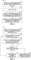
- FIG. 6 is a flowchart that illustrates an example of a method 600 for operating a system to generate a cut guide positioning plan for positioning a cut guide onto a target bone.
- the cut guide 100 and the cut guide positioning system 200 can be configured to perform method 600, including its various embodiments discussed in this document.
- a cut guide can be selected such as by a cut guide selection module.
- the cut guide can be selected based on the size, shape, anatomy, and mechanical properties of the target bone, such that the selected cut guide can be appropriately used in assisting bone cuts on the target bone.
- the selected cut guide such as the cut guide 100, can include one or more guide members on the body of the cut guide with pre-determined cutting trajectories, and a plurality of landing members each including a respective coupling feature configured to removably couple to a landing site of the target bone.
- a generic post-coupling bone model (M coupling ) is received, such as by using the model receiver module 210.
- the model M coupling may be derived from a plurality of images of bones taken from a group of subjects, where the images can have anatomical origin similar to the target bone representation X pre-coupling .
- the model M coupling can be in a form of a parametric model, a statistical model, a shape-based model such as a statistical shape model, a volumetric model, an elastic model, a geometric spine model, or a finite element model.
- the model M coupling can include representations of two or more coupling receptacles produced at respective two or more landing sites on the bone.
- the portion of the M coupling that contains the coupling receptacle representation can be differentiated from other portions of the M coupling free of coupling receptacle representation, and a registration area free of coupling receptacle representation can be identified from the segments of the M coupling .
- a desired transformation can be determined which minimizes the difference between the identified coupling receptacle-free segments on the M coupling and the corresponding segments of X pre-coupling .
- the desired transformation can then be applied to the model M coupling to create the registered post-coupling model M* coupling .
- the cut guide positioning plan can be used by a system, such as the cut guide positioning system 200, for locating the landing sites on the target bone, and controlling a surgical cutting tool to produce two or more coupling receptacles to desired size and shape at the landing sites.
- the surgical cutting tool such as a surgical drill, a surgical mill, a surgical saw, or other surgical equipment, can be manually operated or driven by an automated computer-controlled system.
- the cut guide can therefore be positioned onto or conform to the target bone via the established coupling between the coupling features on the cut guide and the coupling receptacles created on the target bone.
- the method 600 can optionally include an operation of processing the interfacing surfaces of the coupling receptacle to allow for an interference fit in at least one dimension between the coupling features and the coupling by compression or by friction.
- the amount of interference can be produced at the coupling receptacle to achieve desired tightness of fit.
- the positioning can be performed manually by an operator or with the assist of an automated system such as a computer-controlled robotic arm. Examples of methods for creating the coupling receptacle in accordance with the cut guide positing plan are discussed below, such as with reference to FIG. 7 .
- the method 600 can further includes providing audio, visual, or other multi-media presentations of the post-coupling bone model M coupling , the registered post-coupling model M* coupling , the target bone representation, among other things.
- the presentation can be displayed on a monitor or other communication interface.
- the presentation formats can also include sound, dialog, text, 2D or 3D graphs, or animations to assist an end-user such as a surgeon during the process of creating and evaluating the cut guide positioning plan.
- Presentation of the coupling between the target bone model and the cut guide including a measurement of relative positions between the coupling feature and the respective coupling receptacle, can also be provided to the end-user when the cut guide is positioned onto or conform to the target bone.
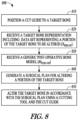
- FIG. 7 is a flowchart that illustrates an example of a method 700 for producing coupling receptacles on a target bone.
- the method 700 which is outside the scope of the claims of this application, can be used for progressively creating bond couplers using a navigation-based feedback-controlled mechanism.
- the method 700 can be an embodiment of producing coupling receptacles on the target bone at 650 in method 600.
- the similarity metric can be provided to the operator such as a surgeon via a displaying module, or to an automated computer-controlled system.
- the similarity metric can be compared to specified criterion such as a pre-determined threshold value. If the similarity metric fails to meet the specified criterion, the coupling receptacle creation process continues at 750 with further bone cut according to the positioning plan, and peri-operative bone representation can be re-generated at 720.
- the navigation-based feedback-controlled coupling receptacle creation process then continues.
- a surgical plan for altering a portion of the target bone can be created when the cut guide is securely positioned onto or conforms to the target bone.
- the post-operative bone model M post-op can be registered to the representation X pre-op to create a registered post-operative bone model M* post-op .
- the registration can include a process of segmentation, model transformation, and matching and alignment between X pre-op and M* post-op .
- the generic post-coupling bone model M post-op can be transformed to create a registered post-operative bone model M* post-op , such as using a comparison between the segment of the M post-op free of resection surface representation and the corresponding segments of the X pre-op .
- One or more segments of the registered post-operative bone model M* post-op can then be matched to the corresponding registration area of the X pre-op .
- the remaining segments of the registered post-operative bone model M* post-op can be aligned with the remaining segments of X pre-op based on the matching.
- a surgical plan can then be generated using the registered post-operative model M* post-op for cutting the target bone until the altered target bone is in substantial conformity with the registered post-operative model M* post-op .
- the orientations of the desired resection surface as defined by the registered post-operative model M* post-op can be compared to the cutting trajectories of the guide members of the cut guide.
- One or more guide members that match the orientation of a portion of the resection surface can then selected.
- An ordered sequence of bone cuts along the trajectories associated with the selected guide members is then determined. The cutting sequence can be determined using the anatomical, geometric, physical and mechanical properties of the portions of the bone to be altered.
- the cutting sequence can also be scheduled considering the locations, sizes, shapes, volumes, or other geometric or morphological descriptors of the coupling receptacles relative to the cutting trajectories. For example, the bone cuts along the cutting trajectories that are spatially farther away from the coupling receptacles can be executed earlier (i.e., at the front of the sequence), the bone cuts along the cutting trajectories that are spatially closer to the coupling receptacles can be executed later (i.e., at a latter part of the sequence), and the bone cuts along the cutting trajectories that intersect with one or more coupling receptacles can be executed last (i.e., at the end of the sequence).
- the ordered bone cuts as such allow the cut guide to remain securely attached to the target bone while performing bone cuts, and prevent a bone cut from interfering with the coupling between the cut guide and the target bone.
- the instructions 924 stored in the machine-readable storage medium 922 include instructions causing the computer system 900 to receive receive a target bone representation including a data set representing two or more landing sites of the target bone (X pre-coupling ), to select a cut guide configured to be adjustably positionable onto or otherwise to conform to the target bone, and to receive a generic post-coupling bone model (M coupling ) including a data set representing a bone having the two or more coupling receptacles.
- the instructions 924 can also store the instructions 924 that cause the computer system 900 to generate a cut guide positioning plan for positioning the cut guide onto or conforming to the target bone.
- machine-readable medium 922 is shown in an example embodiment to be a single medium, the term “machine-readable medium” may include a single medium or multiple media (e.g., a centralized or distributed database, and/or associated caches and servers) that store the one or more instructions or data structures.
- the term “machine-readable storage medium” shall also be taken to include any tangible medium that is capable of storing, encoding or carrying instructions for execution by the machine and that cause the machine to perform any one or more of the methods of the present invention, or that is capable of storing, encoding or carrying data structures used by or associated with such instructions.
- the term “machine-readable storage medium” shall accordingly be taken to include, but not be limited to, solid-state memories, and optical and magnetic media.
- the instructions 924 may further be transmitted or received over a communications network 926 using a transmission medium.
- the instructions 924 may be transmitted using the network interface device 920 and any one of a number of well-known transfer protocols (e.g., HTTP).
- Examples of communication networks include a LAN, a WAN, the Internet, mobile telephone networks, plain old telephone (POTS) networks, and wireless data networks (e.g., Wi-Fi and WiMAX networks).
- POTS plain old telephone
- Wi-Fi and WiMAX wireless data networks
- transmission medium shall be taken to include any intangible medium that is capable of storing, encoding or carrying instructions for execution by the machine, and includes digital or analog communications signals or other intangible media to facilitate communication of such software.
- Method examples described herein can be machine or computer-implemented at least in part. Some examples can include a computer-readable medium or machine-readable medium encoded with instructions operable to configure an electronic device to perform methods as described in the above examples.
- An implementation of such methods can include code, such as microcode, assembly language code, a higher-level language code, or the like. Such code can include computer readable instructions for performing various methods. The code may form portions of computer program products. Further, in an example, the code can be tangibly stored on one or more volatile, non-transitory, or non-volatile tangible computer-readable media, such as during execution or at other times.
- Examples of these tangible computer-readable media can include, but are not limited to, hard disks, removable magnetic disks, removable optical disks (e.g., compact disks and digital video disks), magnetic cassettes, memory cards or sticks, random access memories (RAMs), read only memories (ROMs), and the like.
Landscapes
- Health & Medical Sciences (AREA)
- Engineering & Computer Science (AREA)
- Medical Informatics (AREA)
- Public Health (AREA)
- Biomedical Technology (AREA)
- Surgery (AREA)
- General Health & Medical Sciences (AREA)
- Life Sciences & Earth Sciences (AREA)
- Nuclear Medicine, Radiotherapy & Molecular Imaging (AREA)
- Epidemiology (AREA)
- Primary Health Care (AREA)
- Molecular Biology (AREA)
- Veterinary Medicine (AREA)
- Animal Behavior & Ethology (AREA)
- Heart & Thoracic Surgery (AREA)
- General Business, Economics & Management (AREA)
- Business, Economics & Management (AREA)
- Oral & Maxillofacial Surgery (AREA)
- Dentistry (AREA)
- Robotics (AREA)
- Orthopedic Medicine & Surgery (AREA)
- Pathology (AREA)
- Data Mining & Analysis (AREA)
- Databases & Information Systems (AREA)
- Urology & Nephrology (AREA)
- Physical Education & Sports Medicine (AREA)
- Transplantation (AREA)
- Surgical Instruments (AREA)
- Radiology & Medical Imaging (AREA)
Claims (13)
- Dispositif chirurgical orthopédique à utiliser pour opérer un os cible (300), comprenant :
un guide de coupe (100) configuré pour être positionné de manière ajustable sur l'os cible (300) ou pour s'y conformer, le guide de coupe (100) comprenant :un corps de guidage (110) formant le guide de coupe (100), le corps de guidage (110) comprenant un ou plusieurs éléments de guidage (120) chacun étant dimensionné, façonné ou autrement configuré pour contraindre et guider un outil de coupe le long d'une trajectoire de coupe respective (150) ; etcomprenant en outre une pluralité d'éléments de réception (130), chacun des éléments de réception (130) comprenant une caractéristique de couplage respective configurée pour s'accoupler de manière amovible à un site de réception de l'os cible (300),le ou les éléments de guidage (120) étant configurés pour guider l'outil de coupe afin de couper l'os cible (300) le long de la trajectoire de coupe respective (150) lorsque la pluralité d'éléments de réception (130) sont couplés au site de réception de l'os cible (300),caractérisé en ce quela caractéristique de couplage de chacun des éléments de réception (130) comprend une partie saillante (131) configurée pour être mise en prise par l'utilisateur final avec un réceptacle de couplage respectif (331) sur le site de réception de l'os cible (300), le réceptacle de couplage (331) comprenant une partie en retrait dimensionnée, façonnée ou autrement configurée pour recevoir et fixer la partie saillante (131) de la caractéristique de couplage respective de chacun de la pluralité d'éléments de réception (130). - Dispositif selon la revendication 1, la pluralité d'éléments de réception (130) étant configurés pour être fixés sur un extérieur du corps de guidage (110).
- Dispositif selon la revendication 1, au moins un de la pluralité d'éléments de réception (130) étant reconfigurable par rapport au corps de guidage (110), l'au moins un élément de réception reconfigurable étant relié au corps de guidage (110) et ayant au moins un degré de liberté de mouvement par rapport au corps de guidage (110).
- Dispositif selon la revendication 3, l'au moins un élément de réception reconfigurable étant configuré pour se verrouiller de manière ajustable sur le corps de guidage (110) lorsque l'au moins un élément de réception reconfigurable est positionné sur le site de réception et fixé à l'os cible (300), ou lorsque l'au moins un élément de réception reconfigurable n'est pas utilisé pour la fixation à l'os cible (300).
- Dispositif selon la revendication 1, les parties saillantes des éléments de réception (130) ne croisant pas les trajectoires de coupe (150) associées au ou aux éléments de guidage (120).
- Dispositif selon la revendication 1, le corps de guidage (110) formant une structure de support du guide de coupe (100), et étant fabriqué à partir d'un métal, d'un alliage ou d'un polymère.
- Dispositif selon la revendication 1, les éléments de guidage (120) comprenant des structures fendues dimensionnées pour recevoir et contraindre solidement l'outil de coupe et permettre à l'outil de coupe de se déplacer librement à l'intérieur de la structure fendue respective.
- Dispositif selon la revendication 1, les éléments de guidage (120) ayant des ouvertures sur un extérieur du corps de guidage (110) dimensionnées pour faciliter le placement de l'outil de coupe dans un ou plusieurs des éléments de guidage (120) et la connexion entre une partie de l'outil de coupe et un dispositif d'entraînement externe pour manipuler l'outil de coupe à l'intérieur des éléments de guidage (120).
- Dispositif selon la revendication 1, le corps de guidage (110) comprenant quatre éléments de guidage (120), un élément de guidage (120) étant orienté horizontalement, un élément de guidage (120) étant orienté verticalement, et deux éléments de guidage (120) étant orientés selon des angles d'inclinaison spécifiés.
- Dispositif selon la revendication 1, une orientation de chaque élément de guidage étant différente d'une orientation de chaque autre élément de guidage.
- Dispositif selon la revendication 1, au moins deux éléments de guidage (120) ayant une même orientation.
- Dispositif selon la revendication 1, la partie saillante ayant une forme de cylindre, de cube, de prisme rectangulaire, de prisme triangulaire, de pyramide ou de cône.
- Dispositif selon la revendication 1, les surfaces d'interface de la partie saillante et du réceptacle de couplage étant traitées pour permettre un ajustement serré dans au moins une dimension, de sorte que la partie saillante est maintenue dans le réceptacle de couplage par compression ou friction.
Applications Claiming Priority (3)
| Application Number | Priority Date | Filing Date | Title |
|---|---|---|---|
| US201461946428P | 2014-02-28 | 2014-02-28 | |
| EP15754408.1A EP3110344B1 (fr) | 2014-02-28 | 2015-02-27 | Système et procédés de positionnement de guide de coupe osseuse |
| PCT/US2015/018155 WO2015131133A1 (fr) | 2014-02-28 | 2015-02-27 | Système et procédés de positionnement de guide de coupe osseuse |
Related Parent Applications (1)
| Application Number | Title | Priority Date | Filing Date |
|---|---|---|---|
| EP15754408.1A Division EP3110344B1 (fr) | 2014-02-28 | 2015-02-27 | Système et procédés de positionnement de guide de coupe osseuse |
Publications (2)
| Publication Number | Publication Date |
|---|---|
| EP3733096A1 EP3733096A1 (fr) | 2020-11-04 |
| EP3733096B1 true EP3733096B1 (fr) | 2025-04-09 |
Family
ID=54006212
Family Applications (2)
| Application Number | Title | Priority Date | Filing Date |
|---|---|---|---|
| EP20157613.9A Active EP3733096B1 (fr) | 2014-02-28 | 2015-02-27 | Système de positionnement de guide de coupe osseuse |
| EP15754408.1A Active EP3110344B1 (fr) | 2014-02-28 | 2015-02-27 | Système et procédés de positionnement de guide de coupe osseuse |
Family Applications After (1)
| Application Number | Title | Priority Date | Filing Date |
|---|---|---|---|
| EP15754408.1A Active EP3110344B1 (fr) | 2014-02-28 | 2015-02-27 | Système et procédés de positionnement de guide de coupe osseuse |
Country Status (6)
| Country | Link |
|---|---|
| US (12) | US10251706B2 (fr) |
| EP (2) | EP3733096B1 (fr) |
| JP (1) | JP2017511232A (fr) |
| AU (1) | AU2015222825B2 (fr) |
| CA (1) | CA2941017A1 (fr) |
| WO (1) | WO2015131133A1 (fr) |
Families Citing this family (31)
| Publication number | Priority date | Publication date | Assignee | Title |
|---|---|---|---|---|
| WO2014137876A2 (fr) | 2013-03-08 | 2014-09-12 | Stryker Corporation | Tampons osseux |
| US10368878B2 (en) | 2013-06-11 | 2019-08-06 | Orthotaxy | System for positioning a surgical device |
| JP2017511232A (ja) | 2014-02-28 | 2017-04-20 | ブルー・ベルト・テクノロジーズ・インコーポレーテッド | 骨切断ガイドを位置決めするためのシステムおよび方法 |
| JP2017506574A (ja) | 2014-02-28 | 2017-03-09 | ブルー・ベルト・テクノロジーズ・インコーポレーテッド | 骨切削ガイドを位置決めするシステムおよび方法 |
| EP3166526A4 (fr) * | 2014-07-07 | 2018-08-01 | Smith&Nephew, Inc. | Précision d'alignement |
| US10045826B2 (en) * | 2015-01-20 | 2018-08-14 | Mako Surgical Corporation | Systems and methods for repairing bone with multiple tools |
| CN105991235B (zh) * | 2015-03-04 | 2020-10-30 | 株式会社Ntt都科摩 | 一种调整编码调制方案的方法、用户设备及基站 |
| US10092361B2 (en) | 2015-09-11 | 2018-10-09 | AOD Holdings, LLC | Intraoperative systems and methods for determining and providing for display a virtual image overlaid onto a visual image of a bone |
| WO2018102527A1 (fr) * | 2016-11-30 | 2018-06-07 | Blue Belt Technologies, Inc. | Placement de broche de bloc de coupe d'implant |
| US11076919B1 (en) | 2017-05-19 | 2021-08-03 | Smith & Nephew, Inc. | Surgical tool position tracking and scoring system |
| DE102018116558A1 (de) * | 2018-07-09 | 2020-01-09 | Aesculap Ag | Medizintechnisches Instrumentarium und Verfahren |
| US11559298B2 (en) | 2018-07-16 | 2023-01-24 | Cilag Gmbh International | Surgical visualization of multiple targets |
| US11744643B2 (en) | 2019-02-04 | 2023-09-05 | Covidien Lp | Systems and methods facilitating pre-operative prediction of post-operative tissue function |
| US12257013B2 (en) | 2019-03-15 | 2025-03-25 | Cilag Gmbh International | Robotic surgical systems with mechanisms for scaling camera magnification according to proximity of surgical tool to tissue |
| AU2020272975B2 (en) * | 2019-04-12 | 2023-12-21 | Mako Surgical Corp. | Robotic systems and methods for manipulating a cutting guide for a surgical instrument |
| CN110840517B (zh) * | 2019-11-20 | 2021-03-12 | 杭州键嘉机器人有限公司 | 骨科z字型切割导向装置及包括该导向装置的骨科手术机器人 |
| US12207881B2 (en) | 2019-12-30 | 2025-01-28 | Cilag Gmbh International | Surgical systems correlating visualization data and powered surgical instrument data |
| US11832996B2 (en) | 2019-12-30 | 2023-12-05 | Cilag Gmbh International | Analyzing surgical trends by a surgical system |
| US11219501B2 (en) | 2019-12-30 | 2022-01-11 | Cilag Gmbh International | Visualization systems using structured light |
| US11776144B2 (en) | 2019-12-30 | 2023-10-03 | Cilag Gmbh International | System and method for determining, adjusting, and managing resection margin about a subject tissue |
| US11759283B2 (en) | 2019-12-30 | 2023-09-19 | Cilag Gmbh International | Surgical systems for generating three dimensional constructs of anatomical organs and coupling identified anatomical structures thereto |
| US11648060B2 (en) | 2019-12-30 | 2023-05-16 | Cilag Gmbh International | Surgical system for overlaying surgical instrument data onto a virtual three dimensional construct of an organ |
| US12053223B2 (en) | 2019-12-30 | 2024-08-06 | Cilag Gmbh International | Adaptive surgical system control according to surgical smoke particulate characteristics |
| US12453592B2 (en) | 2019-12-30 | 2025-10-28 | Cilag Gmbh International | Adaptive surgical system control according to surgical smoke cloud characteristics |
| US12002571B2 (en) | 2019-12-30 | 2024-06-04 | Cilag Gmbh International | Dynamic surgical visualization systems |
| US11744667B2 (en) | 2019-12-30 | 2023-09-05 | Cilag Gmbh International | Adaptive visualization by a surgical system |
| US11896442B2 (en) | 2019-12-30 | 2024-02-13 | Cilag Gmbh International | Surgical systems for proposing and corroborating organ portion removals |
| US11284963B2 (en) | 2019-12-30 | 2022-03-29 | Cilag Gmbh International | Method of using imaging devices in surgery |
| US20230012775A1 (en) * | 2021-07-16 | 2023-01-19 | Nuvera Medical, Inc. | Cable routing and assemblies for medical device handles |
| US11771440B1 (en) | 2022-08-01 | 2023-10-03 | Kevin Ray Myers | Burring devices, systems, and methods |
| US20260047888A1 (en) * | 2022-09-09 | 2026-02-19 | Howmedica Osteonics Corp. | Mixed reality bone graft shaping |
Family Cites Families (84)
| Publication number | Priority date | Publication date | Assignee | Title |
|---|---|---|---|---|
| US4524766A (en) * | 1982-01-07 | 1985-06-25 | Petersen Thomas D | Surgical knee alignment method and system |
| US4759350A (en) | 1986-10-17 | 1988-07-26 | Dunn Harold K | Instruments for shaping distal femoral and proximal tibial surfaces |
| US4841975A (en) | 1987-04-15 | 1989-06-27 | Cemax, Inc. | Preoperative planning of bone cuts and joint replacement using radiant energy scan imaging |
| DE3717871C3 (de) | 1987-05-27 | 1995-05-04 | Georg Prof Dr Schloendorff | Verfahren und Vorrichtung zum reproduzierbaren optischen Darstellen eines chirururgischen Eingriffes |
| DE3884800D1 (de) | 1987-05-27 | 1993-11-11 | Schloendorff Georg Prof Dr | Verfahren und vorrichtung zur reproduzierbaren optischen darstellung eines chirurgischen eingriffes. |
| US4979949A (en) | 1988-04-26 | 1990-12-25 | The Board Of Regents Of The University Of Washington | Robot-aided system for surgery |
| US5086401A (en) | 1990-05-11 | 1992-02-04 | International Business Machines Corporation | Image-directed robotic system for precise robotic surgery including redundant consistency checking |
| US5129909A (en) * | 1991-03-13 | 1992-07-14 | Sutherland Charles J | Apparatus and method for making precise bone cuts in total knee replacement |
| US5344423A (en) | 1992-02-06 | 1994-09-06 | Zimmer, Inc. | Apparatus and method for milling bone |
| US5474559A (en) * | 1993-07-06 | 1995-12-12 | Zimmer, Inc. | Femoral milling instrumentation for use in total knee arthroplasty with optional cutting guide attachment |
| US5496324A (en) | 1994-06-20 | 1996-03-05 | Zimmer, Inc. | Proximal body milling apparatus |
| US5514139A (en) * | 1994-09-02 | 1996-05-07 | Hudson Surgical Design, Inc. | Method and apparatus for femoral resection |
| US5682886A (en) | 1995-12-26 | 1997-11-04 | Musculographics Inc | Computer-assisted surgical system |
| US5824085A (en) | 1996-09-30 | 1998-10-20 | Integrated Surgical Systems, Inc. | System and method for cavity generation for surgical planning and initial placement of a bone prosthesis |
| US5880976A (en) | 1997-02-21 | 1999-03-09 | Carnegie Mellon University | Apparatus and method for facilitating the implantation of artificial components in joints |
| US6205411B1 (en) | 1997-02-21 | 2001-03-20 | Carnegie Mellon University | Computer-assisted surgery planner and intra-operative guidance system |
| US5916220A (en) | 1998-02-02 | 1999-06-29 | Medidea, Llc | Bone cutting guide and method to accommodate different-sized implants |
| US6701174B1 (en) | 2000-04-07 | 2004-03-02 | Carnegie Mellon University | Computer-aided bone distraction |
| US6711432B1 (en) * | 2000-10-23 | 2004-03-23 | Carnegie Mellon University | Computer-aided orthopedic surgery |
| ATE394719T1 (de) | 2001-01-29 | 2008-05-15 | Acrobot Company Ltd | Roboter mit aktiven beschränkungen |
| US8062377B2 (en) * | 2001-03-05 | 2011-11-22 | Hudson Surgical Design, Inc. | Methods and apparatus for knee arthroplasty |
| US20030153978A1 (en) | 2002-02-08 | 2003-08-14 | Whiteside Biomechanics, Inc. | Apparatus and method of ligament balancing and component fit check in total knee arthroplasty |
| US7747311B2 (en) | 2002-03-06 | 2010-06-29 | Mako Surgical Corp. | System and method for interactive haptic positioning of a medical device |
| US9155544B2 (en) | 2002-03-20 | 2015-10-13 | P Tech, Llc | Robotic systems and methods |
| US6757582B2 (en) | 2002-05-03 | 2004-06-29 | Carnegie Mellon University | Methods and systems to control a shaping tool |
| US8801720B2 (en) | 2002-05-15 | 2014-08-12 | Otismed Corporation | Total joint arthroplasty system |
| WO2003105659A2 (fr) | 2002-06-17 | 2003-12-24 | Mazor Surgical Technologies Ltd. | Robot concu pour etre utilise avec des pieces orthopediques |
| US7736368B2 (en) | 2002-08-23 | 2010-06-15 | Orthosoft Inc. | Surgical universal positioning block and tool guide |
| US8052695B2 (en) | 2002-10-11 | 2011-11-08 | Ge Medical Systems Global Technology Company Llc | Adjustable instruments for use with an electromagnetic localizer |
| US7029477B2 (en) * | 2002-12-20 | 2006-04-18 | Zimmer Technology, Inc. | Surgical instrument and positioning method |
| WO2005048851A1 (fr) | 2003-11-14 | 2005-06-02 | Smith & Nephew, Inc. | Systemes coupants ajustables de chirurgie |
| US7815645B2 (en) | 2004-01-14 | 2010-10-19 | Hudson Surgical Design, Inc. | Methods and apparatus for pinplasty bone resection |
| US20050171545A1 (en) | 2004-01-30 | 2005-08-04 | Howmedica Osteonics Corp. | Knee computer-aided navigation instruments |
| US7608079B1 (en) | 2004-03-05 | 2009-10-27 | Biomet Manufacturing Corp. | Unicondylar knee apparatus and system |
| US20050234465A1 (en) | 2004-03-31 | 2005-10-20 | Mccombs Daniel L | Guided saw with pins |
| ATE422847T1 (de) * | 2004-12-08 | 2009-03-15 | Perception Raisonnement Action | Vorrichtung zur positionierung einer knochenschnittführung |
| US20060195111A1 (en) * | 2005-01-25 | 2006-08-31 | Orthosoft Inc. | Universal positioning block assembly |
| US7374563B2 (en) | 2005-02-18 | 2008-05-20 | Howmedica Osteonics Corp. | Apparatus and method for guiding a surgical instrument for shaping the end of a bone |
| GB0504172D0 (en) | 2005-03-01 | 2005-04-06 | King S College London | Surgical planning |
| WO2006106419A2 (fr) | 2005-04-07 | 2006-10-12 | Perception Raisonnement Action En Medecine | Ensemble de guidage robotique conçu pour etre utilise dans des applications de chirurgie assistee par ordinateur |
| US7609649B1 (en) | 2005-04-26 | 2009-10-27 | Cisco Technology, Inc. | Methods and apparatus for improving network based virtualization performance |
| WO2006136955A1 (fr) | 2005-06-03 | 2006-12-28 | Depuy Ireland Limited | Instrument utilise dans une operation de remplacement d'articulation |
| US20070118055A1 (en) | 2005-11-04 | 2007-05-24 | Smith & Nephew, Inc. | Systems and methods for facilitating surgical procedures involving custom medical implants |
| US8798711B2 (en) | 2006-02-09 | 2014-08-05 | Biosense Webster, Inc. | Shielding of catheter handle |
| US20070239153A1 (en) | 2006-02-22 | 2007-10-11 | Hodorek Robert A | Computer assisted surgery system using alternative energy technology |
| US8282646B2 (en) | 2006-02-27 | 2012-10-09 | Biomet Manufacturing Corp. | Patient specific knee alignment guide and associated method |
| US7949386B2 (en) | 2006-03-21 | 2011-05-24 | A2 Surgical | Computer-aided osteoplasty surgery system |
| US8016833B2 (en) * | 2006-12-20 | 2011-09-13 | Howmedica Osteonics Corp. | Femoral cutting block |
| WO2008118524A2 (fr) | 2007-01-26 | 2008-10-02 | Zimmer, Inc. | Système d'articulation instrumenté |
| GB2447702A (en) * | 2007-03-23 | 2008-09-24 | Univ Leeds | Surgical bone cutting template |
| GB0712290D0 (en) * | 2007-06-25 | 2007-08-01 | Depuy Orthopaedie Gmbh | Surgical instrument |
| US8197486B2 (en) * | 2007-09-20 | 2012-06-12 | Depuy Products, Inc. | Surgical cutting guide |
| US8398645B2 (en) | 2007-09-30 | 2013-03-19 | DePuy Synthes Products, LLC | Femoral tibial customized patient-specific orthopaedic surgical instrumentation |
| WO2011106399A1 (fr) | 2010-02-25 | 2011-09-01 | Depuy Products, Inc. | Blocs de coupe osseuse spécifiques à un patient personnalisés |
| US9265589B2 (en) | 2007-11-06 | 2016-02-23 | Medtronic Navigation, Inc. | System and method for navigated drill guide |
| KR100873014B1 (ko) | 2008-05-16 | 2008-12-09 | 의료법인 장산의료재단 | 로봇을 이용한 관절 절삭시스템 |
| US8078440B2 (en) * | 2008-09-19 | 2011-12-13 | Smith & Nephew, Inc. | Operatively tuning implants for increased performance |
| RU2011149966A (ru) | 2009-06-24 | 2013-07-27 | Кастом Мед Ортопэдикс (Проприетери) Лимитед | Направляющее приспособление и система ориентации для операции на бедренной кости |
| US8403935B2 (en) | 2009-11-10 | 2013-03-26 | Wright Medical Technology, Inc. | Adjustable revision guide |
| WO2011130567A2 (fr) * | 2010-04-14 | 2011-10-20 | Smith & Nephew, Inc. | Systèmes et méthodes pour des interventions chirurgicales assistées par ordinateur basées sur le patient |
| WO2011156755A2 (fr) * | 2010-06-11 | 2011-12-15 | Smith & Nephew, Inc. | Instruments adaptés aux patients |
| US9011453B2 (en) | 2010-09-10 | 2015-04-21 | Zimmer, Inc. | Bone preserving intraoperative downsizing system for orthopaedic implants |
| US8617170B2 (en) | 2010-09-29 | 2013-12-31 | DePuy Synthes Products, LLC | Customized patient-specific computer controlled cutting system and method |
| US10070869B2 (en) | 2011-02-25 | 2018-09-11 | Orthosoft Inc. | Bone and tool tracking with MEMS in computer-assisted surgery |
| US8715289B2 (en) | 2011-04-15 | 2014-05-06 | Biomet Manufacturing, Llc | Patient-specific numerically controlled instrument |
| US9220510B2 (en) | 2011-06-15 | 2015-12-29 | Perception Raisonnement Action En Medecine | System and method for bone preparation for an implant |
| EP2739251A4 (fr) * | 2011-08-03 | 2015-07-29 | Conformis Inc | Conception, sélection, fabrication et implantation d'implants articulaires, conceptions et outils de guidage associés adaptés au patient et améliorés |
| US9289264B2 (en) | 2011-12-29 | 2016-03-22 | Mako Surgical Corp. | Systems and methods for guiding an instrument using haptic object with collapsing geometry |
| US9155555B2 (en) | 2012-01-31 | 2015-10-13 | Medtronic Xomed, Inc. | Surgical instrument with distal bearing assembly |
| WO2013136303A1 (fr) | 2012-03-16 | 2013-09-19 | Custom Med Orthopaedics Proprietary Limited | Guide de positionnement pour positionner un ensemble formant guide de découpe osseuse et un système de guidage de découpe osseuse |
| US20130317523A1 (en) | 2012-05-22 | 2013-11-28 | Todd Borus | Total Knee Arthroplasty Apparatus and Method of Use |
| WO2014131007A1 (fr) | 2013-02-25 | 2014-08-28 | Stryker Corporation | Instrumentation guidée anatomiquement pour remplacement de gorge trochléenne |
| WO2014137876A2 (fr) | 2013-03-08 | 2014-09-12 | Stryker Corporation | Tampons osseux |
| EP2967522A4 (fr) | 2013-03-13 | 2016-11-02 | Think Surgical Inc | Systèmes et procédés pour la planification préopératoire et le placement de tunnel osseux précis pour une reconstruction de ligament |
| WO2014145373A2 (fr) | 2013-03-15 | 2014-09-18 | Curexo Technology Corporation | Processus destiné à la création de cavités osseuses destinées à la guérison osseuse |
| US9427336B2 (en) | 2013-08-23 | 2016-08-30 | Stryker Corporation | Intraoperative dynamic trialing |
| DE102014105311A1 (de) | 2013-12-17 | 2015-06-18 | Ergosurg Gmbh | Verfahren und System zur steuerbaren Verstellung der Abtragsleistung von handgeführten material- und gewebetrennenden Werkzeugen und Effektoren |
| JP2017511232A (ja) | 2014-02-28 | 2017-04-20 | ブルー・ベルト・テクノロジーズ・インコーポレーテッド | 骨切断ガイドを位置決めするためのシステムおよび方法 |
| JP2017506574A (ja) | 2014-02-28 | 2017-03-09 | ブルー・ベルト・テクノロジーズ・インコーポレーテッド | 骨切削ガイドを位置決めするシステムおよび方法 |
| US10470821B2 (en) | 2014-03-05 | 2019-11-12 | Blue Belt Technologies, Inc. | Computer-aided prosthesis alignment |
| US20160045268A1 (en) | 2014-08-15 | 2016-02-18 | Stryker Corporation | Surgical plan options for robotic machining |
| US9414846B2 (en) | 2014-10-22 | 2016-08-16 | Bullseye Hip Replacement, Llc | Devices and methods for knee replacement |
| US10448958B2 (en) | 2015-06-23 | 2019-10-22 | The Trustees Of Dartmouth College | Method of enhancing interdigitation of bone cement to bone for attachment of prosthesis to bone during arthroplasty |
| CA2991616A1 (fr) | 2015-07-08 | 2017-01-12 | Zimmer, Inc. | Instruments specifiques a un patient pour la chirurgie de revision d'implant |
-
2015
- 2015-02-27 JP JP2016572366A patent/JP2017511232A/ja active Pending
- 2015-02-27 EP EP20157613.9A patent/EP3733096B1/fr active Active
- 2015-02-27 AU AU2015222825A patent/AU2015222825B2/en active Active
- 2015-02-27 WO PCT/US2015/018155 patent/WO2015131133A1/fr not_active Ceased
- 2015-02-27 CA CA2941017A patent/CA2941017A1/fr not_active Abandoned
- 2015-02-27 US US15/247,448 patent/US10251706B2/en active Active
- 2015-02-27 EP EP15754408.1A patent/EP3110344B1/fr active Active
- 2015-02-27 US US14/634,363 patent/US20150245878A1/en not_active Abandoned
-
2016
- 2016-08-26 US US15/248,884 patent/US9855106B2/en active Active
-
2017
- 2017-11-16 US US15/815,163 patent/US10667865B2/en active Active
-
2018
- 2018-06-22 US US16/016,535 patent/US10925673B2/en active Active
- 2018-06-22 US US16/016,541 patent/US10918440B2/en active Active
- 2018-06-22 US US16/016,527 patent/US11020185B2/en active Active
- 2018-06-27 US US16/020,575 patent/US10939961B2/en active Active
-
2019
- 2019-02-12 US US16/273,906 patent/US10912614B2/en active Active
-
2020
- 2020-01-10 US US16/739,793 patent/US10898269B2/en active Active
-
2021
- 2021-05-04 US US17/307,574 patent/US12029495B2/en active Active
-
2024
- 2024-06-14 US US18/744,172 patent/US20240325087A1/en active Pending
Also Published As
| Publication number | Publication date |
|---|---|
| US9855106B2 (en) | 2018-01-02 |
| US12029495B2 (en) | 2024-07-09 |
| US10898269B2 (en) | 2021-01-26 |
| JP2017511232A (ja) | 2017-04-20 |
| US10918440B2 (en) | 2021-02-16 |
| US20180303554A1 (en) | 2018-10-25 |
| EP3110344A4 (fr) | 2017-11-15 |
| AU2015222825A1 (en) | 2016-09-15 |
| CA2941017A1 (fr) | 2015-09-03 |
| US10925673B2 (en) | 2021-02-23 |
| US20200146752A1 (en) | 2020-05-14 |
| US20210251693A1 (en) | 2021-08-19 |
| US20180071028A1 (en) | 2018-03-15 |
| US20150245878A1 (en) | 2015-09-03 |
| US10939961B2 (en) | 2021-03-09 |
| WO2015131133A1 (fr) | 2015-09-03 |
| US20180296275A1 (en) | 2018-10-18 |
| US11020185B2 (en) | 2021-06-01 |
| US10912614B2 (en) | 2021-02-09 |
| EP3110344A1 (fr) | 2017-01-04 |
| EP3733096A1 (fr) | 2020-11-04 |
| US20240325087A1 (en) | 2024-10-03 |
| US10667865B2 (en) | 2020-06-02 |
| US20190175280A1 (en) | 2019-06-13 |
| AU2015222825B2 (en) | 2019-10-31 |
| EP3110344B1 (fr) | 2020-02-19 |
| US20180296276A1 (en) | 2018-10-18 |
| US20170014190A1 (en) | 2017-01-19 |
| US10251706B2 (en) | 2019-04-09 |
| US20180296274A1 (en) | 2018-10-18 |
| US20160361072A1 (en) | 2016-12-15 |
Similar Documents
| Publication | Publication Date | Title |
|---|---|---|
| US12029495B2 (en) | System and methods for positioning bone cut guide | |
| US20240096508A1 (en) | Systems and methods for using generic anatomy models in surgical planning | |
| US9707044B2 (en) | Surgical guides from scanned implant data | |
| AU2024202787B2 (en) | Computer-implemented surgical planning based on bone loss during orthopedic revision surgery | |
| US12433761B1 (en) | Systems and methods for determining the shape of spinal rods and spinal interbody devices for use with augmented reality displays, navigation systems and robots in minimally invasive spine procedures |
Legal Events
| Date | Code | Title | Description |
|---|---|---|---|
| PUAI | Public reference made under article 153(3) epc to a published international application that has entered the european phase |
Free format text: ORIGINAL CODE: 0009012 |
|
| STAA | Information on the status of an ep patent application or granted ep patent |
Free format text: STATUS: THE APPLICATION HAS BEEN PUBLISHED |
|
| AC | Divisional application: reference to earlier application |
Ref document number: 3110344 Country of ref document: EP Kind code of ref document: P |
|
| AK | Designated contracting states |
Kind code of ref document: A1 Designated state(s): AL AT BE BG CH CY CZ DE DK EE ES FI FR GB GR HR HU IE IS IT LI LT LU LV MC MK MT NL NO PL PT RO RS SE SI SK SM TR |
|
| STAA | Information on the status of an ep patent application or granted ep patent |
Free format text: STATUS: REQUEST FOR EXAMINATION WAS MADE |
|
| 17P | Request for examination filed |
Effective date: 20210430 |
|
| RBV | Designated contracting states (corrected) |
Designated state(s): AL AT BE BG CH CY CZ DE DK EE ES FI FR GB GR HR HU IE IS IT LI LT LU LV MC MK MT NL NO PL PT RO RS SE SI SK SM TR |
|
| RAP3 | Party data changed (applicant data changed or rights of an application transferred) |
Owner name: BLUE BELT TECHNOLOGIES, INC. |
|
| STAA | Information on the status of an ep patent application or granted ep patent |
Free format text: STATUS: EXAMINATION IS IN PROGRESS |
|
| 17Q | First examination report despatched |
Effective date: 20231018 |
|
| GRAP | Despatch of communication of intention to grant a patent |
Free format text: ORIGINAL CODE: EPIDOSNIGR1 |
|
| STAA | Information on the status of an ep patent application or granted ep patent |
Free format text: STATUS: GRANT OF PATENT IS INTENDED |
|
| INTG | Intention to grant announced |
Effective date: 20241002 |
|
| P01 | Opt-out of the competence of the unified patent court (upc) registered |
Free format text: CASE NUMBER: APP_55584/2024 Effective date: 20241010 |
|
| GRAS | Grant fee paid |
Free format text: ORIGINAL CODE: EPIDOSNIGR3 |
|
| GRAA | (expected) grant |
Free format text: ORIGINAL CODE: 0009210 |
|
| STAA | Information on the status of an ep patent application or granted ep patent |
Free format text: STATUS: THE PATENT HAS BEEN GRANTED |
|
| AC | Divisional application: reference to earlier application |
Ref document number: 3110344 Country of ref document: EP Kind code of ref document: P |
|
| AK | Designated contracting states |
Kind code of ref document: B1 Designated state(s): AL AT BE BG CH CY CZ DE DK EE ES FI FR GB GR HR HU IE IS IT LI LT LU LV MC MK MT NL NO PL PT RO RS SE SI SK SM TR |
|
| REG | Reference to a national code |
Ref country code: GB Ref legal event code: FG4D |
|
| REG | Reference to a national code |
Ref country code: CH Ref legal event code: EP |
|
| REG | Reference to a national code |
Ref country code: DE Ref legal event code: R096 Ref document number: 602015091427 Country of ref document: DE |
|
| REG | Reference to a national code |
Ref country code: IE Ref legal event code: FG4D |
|
| REG | Reference to a national code |
Ref country code: NL Ref legal event code: MP Effective date: 20250409 |
|
| PG25 | Lapsed in a contracting state [announced via postgrant information from national office to epo] |
Ref country code: NL Free format text: LAPSE BECAUSE OF FAILURE TO SUBMIT A TRANSLATION OF THE DESCRIPTION OR TO PAY THE FEE WITHIN THE PRESCRIBED TIME-LIMIT Effective date: 20250409 |
|
| REG | Reference to a national code |
Ref country code: AT Ref legal event code: MK05 Ref document number: 1782807 Country of ref document: AT Kind code of ref document: T Effective date: 20250409 |
|
| PG25 | Lapsed in a contracting state [announced via postgrant information from national office to epo] |
Ref country code: FI Free format text: LAPSE BECAUSE OF FAILURE TO SUBMIT A TRANSLATION OF THE DESCRIPTION OR TO PAY THE FEE WITHIN THE PRESCRIBED TIME-LIMIT Effective date: 20250409 Ref country code: ES Free format text: LAPSE BECAUSE OF FAILURE TO SUBMIT A TRANSLATION OF THE DESCRIPTION OR TO PAY THE FEE WITHIN THE PRESCRIBED TIME-LIMIT Effective date: 20250409 Ref country code: PT Free format text: LAPSE BECAUSE OF FAILURE TO SUBMIT A TRANSLATION OF THE DESCRIPTION OR TO PAY THE FEE WITHIN THE PRESCRIBED TIME-LIMIT Effective date: 20250811 |
|
| REG | Reference to a national code |
Ref country code: LT Ref legal event code: MG9D |
|
| PG25 | Lapsed in a contracting state [announced via postgrant information from national office to epo] |
Ref country code: GR Free format text: LAPSE BECAUSE OF FAILURE TO SUBMIT A TRANSLATION OF THE DESCRIPTION OR TO PAY THE FEE WITHIN THE PRESCRIBED TIME-LIMIT Effective date: 20250710 Ref country code: NO Free format text: LAPSE BECAUSE OF FAILURE TO SUBMIT A TRANSLATION OF THE DESCRIPTION OR TO PAY THE FEE WITHIN THE PRESCRIBED TIME-LIMIT Effective date: 20250709 |
|
| PG25 | Lapsed in a contracting state [announced via postgrant information from national office to epo] |
Ref country code: PL Free format text: LAPSE BECAUSE OF FAILURE TO SUBMIT A TRANSLATION OF THE DESCRIPTION OR TO PAY THE FEE WITHIN THE PRESCRIBED TIME-LIMIT Effective date: 20250409 |
|
| PG25 | Lapsed in a contracting state [announced via postgrant information from national office to epo] |
Ref country code: BG Free format text: LAPSE BECAUSE OF FAILURE TO SUBMIT A TRANSLATION OF THE DESCRIPTION OR TO PAY THE FEE WITHIN THE PRESCRIBED TIME-LIMIT Effective date: 20250409 |
|
| PG25 | Lapsed in a contracting state [announced via postgrant information from national office to epo] |
Ref country code: HR Free format text: LAPSE BECAUSE OF FAILURE TO SUBMIT A TRANSLATION OF THE DESCRIPTION OR TO PAY THE FEE WITHIN THE PRESCRIBED TIME-LIMIT Effective date: 20250409 |
|
| PG25 | Lapsed in a contracting state [announced via postgrant information from national office to epo] |
Ref country code: AT Free format text: LAPSE BECAUSE OF FAILURE TO SUBMIT A TRANSLATION OF THE DESCRIPTION OR TO PAY THE FEE WITHIN THE PRESCRIBED TIME-LIMIT Effective date: 20250409 |
|
| PG25 | Lapsed in a contracting state [announced via postgrant information from national office to epo] |
Ref country code: RS Free format text: LAPSE BECAUSE OF FAILURE TO SUBMIT A TRANSLATION OF THE DESCRIPTION OR TO PAY THE FEE WITHIN THE PRESCRIBED TIME-LIMIT Effective date: 20250709 |
|
| PG25 | Lapsed in a contracting state [announced via postgrant information from national office to epo] |
Ref country code: IS Free format text: LAPSE BECAUSE OF FAILURE TO SUBMIT A TRANSLATION OF THE DESCRIPTION OR TO PAY THE FEE WITHIN THE PRESCRIBED TIME-LIMIT Effective date: 20250809 |
|
| PG25 | Lapsed in a contracting state [announced via postgrant information from national office to epo] |
Ref country code: LV Free format text: LAPSE BECAUSE OF FAILURE TO SUBMIT A TRANSLATION OF THE DESCRIPTION OR TO PAY THE FEE WITHIN THE PRESCRIBED TIME-LIMIT Effective date: 20250409 |
|
| REG | Reference to a national code |
Ref country code: DE Ref legal event code: R097 Ref document number: 602015091427 Country of ref document: DE |
|
| PG25 | Lapsed in a contracting state [announced via postgrant information from national office to epo] |
Ref country code: SM Free format text: LAPSE BECAUSE OF FAILURE TO SUBMIT A TRANSLATION OF THE DESCRIPTION OR TO PAY THE FEE WITHIN THE PRESCRIBED TIME-LIMIT Effective date: 20250409 Ref country code: DK Free format text: LAPSE BECAUSE OF FAILURE TO SUBMIT A TRANSLATION OF THE DESCRIPTION OR TO PAY THE FEE WITHIN THE PRESCRIBED TIME-LIMIT Effective date: 20250409 |
|
| PGFP | Annual fee paid to national office [announced via postgrant information from national office to epo] |
Ref country code: FR Payment date: 20251231 Year of fee payment: 12 |
|
| PG25 | Lapsed in a contracting state [announced via postgrant information from national office to epo] |
Ref country code: CZ Free format text: LAPSE BECAUSE OF FAILURE TO SUBMIT A TRANSLATION OF THE DESCRIPTION OR TO PAY THE FEE WITHIN THE PRESCRIBED TIME-LIMIT Effective date: 20250409 |
|
| PG25 | Lapsed in a contracting state [announced via postgrant information from national office to epo] |
Ref country code: EE Free format text: LAPSE BECAUSE OF FAILURE TO SUBMIT A TRANSLATION OF THE DESCRIPTION OR TO PAY THE FEE WITHIN THE PRESCRIBED TIME-LIMIT Effective date: 20250409 |
|
| PG25 | Lapsed in a contracting state [announced via postgrant information from national office to epo] |
Ref country code: RO Free format text: LAPSE BECAUSE OF FAILURE TO SUBMIT A TRANSLATION OF THE DESCRIPTION OR TO PAY THE FEE WITHIN THE PRESCRIBED TIME-LIMIT Effective date: 20250409 Ref country code: SK Free format text: LAPSE BECAUSE OF FAILURE TO SUBMIT A TRANSLATION OF THE DESCRIPTION OR TO PAY THE FEE WITHIN THE PRESCRIBED TIME-LIMIT Effective date: 20250409 |
|
| PG25 | Lapsed in a contracting state [announced via postgrant information from national office to epo] |
Ref country code: IT Free format text: LAPSE BECAUSE OF FAILURE TO SUBMIT A TRANSLATION OF THE DESCRIPTION OR TO PAY THE FEE WITHIN THE PRESCRIBED TIME-LIMIT Effective date: 20250409 |
|
| PLBE | No opposition filed within time limit |
Free format text: ORIGINAL CODE: 0009261 |
|
| STAA | Information on the status of an ep patent application or granted ep patent |
Free format text: STATUS: NO OPPOSITION FILED WITHIN TIME LIMIT |
|
| REG | Reference to a national code |
Ref country code: CH Ref legal event code: L10 Free format text: ST27 STATUS EVENT CODE: U-0-0-L10-L00 (AS PROVIDED BY THE NATIONAL OFFICE) Effective date: 20260218 |
|
| REG | Reference to a national code |
Ref country code: CH Ref legal event code: U11 Free format text: ST27 STATUS EVENT CODE: U-0-0-U10-U11 (AS PROVIDED BY THE NATIONAL OFFICE) Effective date: 20260301 |
|
| 26N | No opposition filed |
Effective date: 20260112 |
|
| PGFP | Annual fee paid to national office [announced via postgrant information from national office to epo] |
Ref country code: GB Payment date: 20260106 Year of fee payment: 12 |
|
| PGFP | Annual fee paid to national office [announced via postgrant information from national office to epo] |
Ref country code: DE Payment date: 20260102 Year of fee payment: 12 |
|
| PGFP | Annual fee paid to national office [announced via postgrant information from national office to epo] |
Ref country code: CH Payment date: 20260301 Year of fee payment: 12 |