EP3733109A1 - Chirurgisches instrument, befestigte vorrichtung, medizinisches behandlungswerkzeug, chirurgischer roboter und ferngesteuertes chirurgisches system - Google Patents
Chirurgisches instrument, befestigte vorrichtung, medizinisches behandlungswerkzeug, chirurgischer roboter und ferngesteuertes chirurgisches system Download PDFInfo
- Publication number
- EP3733109A1 EP3733109A1 EP18895295.6A EP18895295A EP3733109A1 EP 3733109 A1 EP3733109 A1 EP 3733109A1 EP 18895295 A EP18895295 A EP 18895295A EP 3733109 A1 EP3733109 A1 EP 3733109A1
- Authority
- EP
- European Patent Office
- Prior art keywords
- medical treatment
- treatment tool
- end part
- engagement
- attachment device
- Prior art date
- Legal status (The legal status is an assumption and is not a legal conclusion. Google has not performed a legal analysis and makes no representation as to the accuracy of the status listed.)
- Withdrawn
Links
Images






Classifications
-
- A—HUMAN NECESSITIES
- A61—MEDICAL OR VETERINARY SCIENCE; HYGIENE
- A61B—DIAGNOSIS; SURGERY; IDENTIFICATION
- A61B34/00—Computer-aided surgery; Manipulators or robots specially adapted for use in surgery
- A61B34/30—Surgical robots
- A61B34/37—Leader-follower robots
-
- A—HUMAN NECESSITIES
- A61—MEDICAL OR VETERINARY SCIENCE; HYGIENE
- A61B—DIAGNOSIS; SURGERY; IDENTIFICATION
- A61B34/00—Computer-aided surgery; Manipulators or robots specially adapted for use in surgery
- A61B34/30—Surgical robots
- A61B34/35—Surgical robots for telesurgery
-
- A—HUMAN NECESSITIES
- A61—MEDICAL OR VETERINARY SCIENCE; HYGIENE
- A61B—DIAGNOSIS; SURGERY; IDENTIFICATION
- A61B34/00—Computer-aided surgery; Manipulators or robots specially adapted for use in surgery
- A61B34/70—Manipulators specially adapted for use in surgery
- A61B34/71—Manipulators operated by drive cable mechanisms
-
- B—PERFORMING OPERATIONS; TRANSPORTING
- B25—HAND TOOLS; PORTABLE POWER-DRIVEN TOOLS; MANIPULATORS
- B25J—MANIPULATORS; CHAMBERS PROVIDED WITH MANIPULATION DEVICES
- B25J9/00—Program-controlled manipulators
- B25J9/02—Program-controlled manipulators characterised by movement of the arms, e.g. cartesian coordinate type
- B25J9/023—Cartesian coordinate type
-
- B—PERFORMING OPERATIONS; TRANSPORTING
- B25—HAND TOOLS; PORTABLE POWER-DRIVEN TOOLS; MANIPULATORS
- B25J—MANIPULATORS; CHAMBERS PROVIDED WITH MANIPULATION DEVICES
- B25J9/00—Program-controlled manipulators
- B25J9/02—Program-controlled manipulators characterised by movement of the arms, e.g. cartesian coordinate type
- B25J9/04—Program-controlled manipulators characterised by movement of the arms, e.g. cartesian coordinate type by rotating at least one arm, excluding the head movement itself, e.g. cylindrical coordinate type or polar coordinate type
- B25J9/041—Cylindrical coordinate type
- B25J9/042—Cylindrical coordinate type comprising an articulated arm
-
- B—PERFORMING OPERATIONS; TRANSPORTING
- B25—HAND TOOLS; PORTABLE POWER-DRIVEN TOOLS; MANIPULATORS
- B25J—MANIPULATORS; CHAMBERS PROVIDED WITH MANIPULATION DEVICES
- B25J9/00—Program-controlled manipulators
- B25J9/10—Program-controlled manipulators characterised by positioning means for manipulator elements
- B25J9/102—Gears specially adapted therefor, e.g. reduction gears
- B25J9/1035—Pinion and fixed rack drivers, e.g. for rotating an upper arm support on the robot base
-
- B—PERFORMING OPERATIONS; TRANSPORTING
- B25—HAND TOOLS; PORTABLE POWER-DRIVEN TOOLS; MANIPULATORS
- B25J—MANIPULATORS; CHAMBERS PROVIDED WITH MANIPULATION DEVICES
- B25J9/00—Program-controlled manipulators
- B25J9/10—Program-controlled manipulators characterised by positioning means for manipulator elements
- B25J9/104—Program-controlled manipulators characterised by positioning means for manipulator elements with cables, chains or ribbons
-
- B—PERFORMING OPERATIONS; TRANSPORTING
- B25—HAND TOOLS; PORTABLE POWER-DRIVEN TOOLS; MANIPULATORS
- B25J—MANIPULATORS; CHAMBERS PROVIDED WITH MANIPULATION DEVICES
- B25J9/00—Program-controlled manipulators
- B25J9/10—Program-controlled manipulators characterised by positioning means for manipulator elements
- B25J9/106—Program-controlled manipulators characterised by positioning means for manipulator elements with articulated links
-
- B—PERFORMING OPERATIONS; TRANSPORTING
- B25—HAND TOOLS; PORTABLE POWER-DRIVEN TOOLS; MANIPULATORS
- B25J—MANIPULATORS; CHAMBERS PROVIDED WITH MANIPULATION DEVICES
- B25J9/00—Program-controlled manipulators
- B25J9/16—Program controls
- B25J9/1628—Program controls characterised by the control loop
- B25J9/1635—Program controls characterised by the control loop flexible-arm control
-
- B—PERFORMING OPERATIONS; TRANSPORTING
- B25—HAND TOOLS; PORTABLE POWER-DRIVEN TOOLS; MANIPULATORS
- B25J—MANIPULATORS; CHAMBERS PROVIDED WITH MANIPULATION DEVICES
- B25J9/00—Program-controlled manipulators
- B25J9/16—Program controls
- B25J9/1656—Program controls characterised by programming, planning systems for manipulators
- B25J9/1669—Program controls characterised by programming, planning systems for manipulators characterised by special application, e.g. multi-arm co-operation, assembly, grasping
-
- A—HUMAN NECESSITIES
- A61—MEDICAL OR VETERINARY SCIENCE; HYGIENE
- A61B—DIAGNOSIS; SURGERY; IDENTIFICATION
- A61B17/00—Surgical instruments, devices or methods
- A61B17/04—Surgical instruments, devices or methods for suturing wounds; Holders or packages for needles or suture materials
- A61B17/06—Needles ; Sutures; Needle-suture combinations; Holders or packages for needles or suture materials
- A61B17/062—Needle manipulators
-
- A—HUMAN NECESSITIES
- A61—MEDICAL OR VETERINARY SCIENCE; HYGIENE
- A61B—DIAGNOSIS; SURGERY; IDENTIFICATION
- A61B17/00—Surgical instruments, devices or methods
- A61B2017/00477—Coupling
-
- A—HUMAN NECESSITIES
- A61—MEDICAL OR VETERINARY SCIENCE; HYGIENE
- A61B—DIAGNOSIS; SURGERY; IDENTIFICATION
- A61B34/00—Computer-aided surgery; Manipulators or robots specially adapted for use in surgery
- A61B34/30—Surgical robots
- A61B2034/301—Surgical robots for introducing or steering flexible instruments inserted into the body, e.g. catheters or endoscopes
-
- A—HUMAN NECESSITIES
- A61—MEDICAL OR VETERINARY SCIENCE; HYGIENE
- A61B—DIAGNOSIS; SURGERY; IDENTIFICATION
- A61B34/00—Computer-aided surgery; Manipulators or robots specially adapted for use in surgery
- A61B34/30—Surgical robots
- A61B2034/305—Details of wrist mechanisms at distal ends of robotic arms
Definitions
- a surgery support robot generally includes a patient-side apparatus including a manipulator on which an appropriate medical treatment tool is attached, and performs a surgery by remotely operating the medical treatment tool.
- a medical treatment tool for example, Patent Document 1 (International Patent Application Publication No. 2000/33755) discloses a surgical instrument that includes a distal end part, a shaft accommodating an elongate element for operating the distal end part, and an interface, such that the interface is configured to be attachable to and detachable from a robot arm.
- the present invention has been made to solve the above problems, and an object thereof is to provide a surgical instrument which has a simple structure and enables replacement of a medical treatment tool at low cost, an attachment device and a medical treatment tool provided thereto, and a surgical robot and a remote system including at least a part thereof.
- the present invention enables a medical treatment tool to be replaced at low cost with a simple configuration.
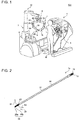
- a remote surgery system 201 includes one or more surgical instruments 100, a medical treatment tool 1a, an endoscope 1b, a remote control apparatus 4, a command input unit 5, and a patient-side apparatus (surgical robot) 10.
- the surgical instrument 100 includes the medical treatment tool 1a.
- the medical treatment tool 1a and the endoscope 1b are attached to the robot arms 3.
- the robot arms 3 are electrically connected to the remote control apparatus 4 in a wired or wireless manner.
- the medical treatment tool 1a includes a distal end device such as grasping forceps (grasper), a needle holder (needle driver), or scissors.
- the patient-side apparatus 10 receives the control signal transmitted from the remote control apparatus 4, and operates according to the operation command included in the received control signal.
- the patient-side apparatus 10 includes a positioner 7, a platform 8 attached to a distal end of the positioner 7, the robot arms 3 attached to the platform 8, and a controller 9.
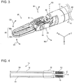
- the distal end part 20 has an end effector 22 and a wrist portion 23, and is operable with multiple degrees of freedom.
- the end effector 22 has a first jaw 22a and a second jaw 22b.
- the first jaw 22a and the second jaw 22b are operable to move toward and away from each other, for example.
- the wrist portion 23 is rotatable about a rotation axis perpendicular to the Z axis, as illustrated by arrows B1 and B2.
- the distal end part 20 further includes a first connecting portion 31 that connects the end effector 22 and the wrist portion 23 and a second connecting portion 32 that connects the wrist portion 23 and the shaft 12.
- the first connecting portion 31 and the second connecting portion 32 are fastening elements, such as bolts, screws, or rotational shafts, which rotatably fix the wrist portion 23 or the end effector 22.
- the medical treatment tool 1a illustrated in FIG. 2 has two retractable elongate elements 14 for rotating the first jaw 22a in the direction of the arrow C2 and includes two retractable elongate elements 14 for rotating the second jaw 22b in the direction of arrow C1 and two retractable elongate elements 14 for rotating the wrist portion 23 in both the directions of the arrows B1 and B2. That is, the medical treatment tool 1a has six retractable flexible elongate elements 14 in this embodiment.
- the elongate elements 14 are rigid members such as rods, one elongate element 14 can be pulled in and pushed out, so that the number of elongate elements 14 can be halved.
- the rigid elongate elements 14 may hinder movements of bent portions of the medical treatment tool 1a, it is preferable to use flexible elongate elements 14 for a complicated structure having a high degree of freedom.
- the operation of the first jaw 22a and the operation of the second jaw 22b can be linked.
- the single elongate element 14 can perform the opening/closing operation of the first jaw 22a and the second jaw 22b.
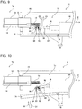
- the maximum dimension of the cross section of the proximal end part 15 orthogonal to the Z axis direction is formed to be slightly larger than the maximum dimension of the cross section of the shaft 12 orthogonal to the Z axis direction.
- the maximum dimension of the cross section of the proximal end part 15 is a dimension that does not hinder the attachment and insertion of the proximal end part 15, and is, for example, not less than one time and not more than two times of the maximum dimension of the cross section of the shaft 12 orthogonal to the Z-axis direction. It is preferable that the maximum dimension of the cross section of the proximal end part 15 is substantially the same as that of the cross section of the shaft 12, and is preferably not more than 1.2 times that of the cross section of the shaft 12.
- the two engagement members 13 and the two elongate elements 14 are provided such that, in the attachment mechanism 73, a first engagement member 13 is connected to a first elongate element 14 and a second engagement member 13 is connected to a second elongate element 14.
- a first drive source 81 operates the first engagement member 13, and a second drive source 81 operates the second engagement member 13.
- the operator W Upon moving the wrist portion 23 in the direction of the arrow B2, the operator W operates the command input unit 5 to rotate the second drive source 81 in the forward direction to operate the second engagement member 13 to retract the second elongate element 14 and to rotate the first drive source 81 in the reverse direction to operate the first engagement member 13 to feed out the first elongate element 14 by the same amount.
- first jaw 22a and the second jaw 22b are also operated in the same operation control, four drive sources 81 are further provided, so that six drive sources 81 in total are provided.
- the operator W rotates the drive source 81 in the forward direction to operate the first engagement member 13 to retract the first elongate element 14, so as to operate the wrist portion 23 in the direction of the arrow B1.
- the second elongate element 14 When rotating the drive source 81 in the reverse direction, the second elongate element 14 is retracted in by the elastic force of the elastic body so that the wrist portion 23 can be moved in the direction of the arrow B2.
- two drive sources 81 are further provided, so that three drive sources 81 in total are provided.
- the attachment device 6 and the medical treatment tool 1a are operated to rotate about the Z-axis in the direction of the arrow A according to the control signal from the controller 9.
- the attachment mechanism 73 includes: a drive source 81 housed in the housing 70, a power conversion mechanism 80 that converts rotational power of the drive source 81 into rotational power in a different direction, an engaging member 84, a connecting member 83 that connects the power conversion mechanism 80 and the drive source 81, and a support portion 85 that supports a rotational shaft of the engaging member 84.
- the attachment mechanism 73 may have a plurality of support portions 85 that respectively support the rotational shafts of the plurality of engagement members 84.
- the drive source 81 is, for example, a servomotor, and operates under the control of the remote control apparatus 4 illustrated in FIG. 1 to operate the engaging member 84 via the connecting member 83 and the power conversion mechanism 80.
- the power conversion mechanism 80 includes a driving side member 82 and a driven side member 88.
- the driving side member 82 is a bevel gear that is provided at the end of the connecting member 83 and that is connected to the drive source 81 via the connecting member 83 and that rotates in conjunction with the drive source 81, for example.
- the engagement member 13 is a worm that is engaged with the helical gear of the engaging member 84 as a worm wheel. That is, the engagement member 13 and the engaging member 84 function as a worm gear.
- the engaging member 84 is rotated by driving the drive source 81, the engagement member 13, which is engaged with the engaging member 84, and the elongate element 14 connected to the engagement member 13 are moved along the Z axis.
- the corresponding first jaw 22a, second jaw 22b, and wrist portion 23 are independently driven.
- the engagement member 13 and the engaging member 84 may be, for example, a rack and pinion instead of the worm gear. That is, the engaging member 84 may be a spur gear, and the engagement member 13 may be a flat plate formed with a groove that is engaged with the spur gear.
- FIG. 7 is a diagram illustrating a state in which the medical treatment tool is attached to the attachment device of the robot arm.
- FIG. 8 is a diagram illustrating a process of detaching the medical treatment tool from the attachment device. Note that the drape 30 is not illustrated in FIGS. 7 and 8 .
- the operator when detaching the medical treatment tool 1a from the attachment device 6, the operator opens the lower lid 72. That is, as illustrated in FIG. 8 , the operator puts his/her finger on the recess 74 and rotates the lower lid 72 in the direction of the arrow D1 about the connecting portion 79.
- the operator When attaching the medical treatment tool 1a to the attachment device 6, the operator inserts the proximal end part 15 of the medical treatment tool 1a through the insertion hole 75 and closes the lower lid 72 in a state where the engaging member 13 is positioned inside the housing 70. In other words, the operator rotates the lower lid 72 about the connecting portion 79 in the direction of the arrow D2.
- the support portion 85, the second connecting portion 83b, the driving side member 82, and the engaging member 84 move, in conjunction with the closing operation of the lower lid 72, to a position where the engaging member 84 and the engagement member 13 are brought into the engaged state.
- the medical treatment tool 1a can be attached to the attachment device 6.
- FIG. 9 is a diagram illustrating a state in which a medical treatment tool is attached to an attachment device of a robot arm according to a first modification.
- FIG. 10 is a diagram illustrating a process of detaching the medical treatment tool from the attachment device according to the first modification. Note that the drape 30 is not illustrated in FIGS. 9 and 10 .
- the attachment mechanism 73 of the robot arm 3 may have a configuration that includes a flexible member 90 provided between the drive source 81 and the driving side member 82 instead of the connecting member 83 illustrated in FIG. 7 , and a support base 87.
- a distal side of the flexible member 90 which is, a side of the flexible member on which the engaging member 84 is located, is biased toward the direction of the arrow E2, which is orthogonal to the Z axis and away from the side on which the engagement member 13 is located.
- the support base 87 presses the flexible member 90 in the direction of the arrow E1, which is orthogonal to the Z axis and toward the side on which the engagement member 13 is located.
- the operator When detaching the medical treatment tool 1a from the attachment device 6, the operator opens the lower lid 72, for example, with putting his / her finger on the recess 74. In other words, the operator rotates the lower lid 72 about the connecting portion 79 in the direction of the arrow D1.
- the support base 87 provided on the lower lid 72 moves, and the flexible member 90, with being pressed by the support base 87, is bent in the direction of the arrow D1, which is the direction away from the side on which the engagement member 13 is located.
- the power conversion mechanism 80 connected to the flexible member 90 and the engaging member 84 supported by the support portion 85 move in the direction of the arrow D1.
- the engagement between the engaging member 84 and the engagement member 13 is released, so that the medical treatment tool 1a can be detached through the insertion hole 75 formed in the attachment device 6.
- the operator When attaching the medical treatment tool 1a to the attachment device 6, the operator inserts the medical treatment tool 1a through the insertion hole 75 and closes the lid 72 in the state where the engaging member 13 is positioned in the housing 70. In other words, the operator rotates the lower lid 72 about the connecting portion 79 in the direction of the arrow D2.
- the engaging member 84 supported by the support portion 85, the flexible member 90, and the power conversion mechanism 80 move so as to be in the state illustrated in FIG. 9 where the engaging member 84 and the engagement member 13 are engaged with each other.
- the medical treatment tool 1a can be attached to the attachment device 6.
- FIG. 11 is a diagram illustrating a state in which a medical treatment tool is attached to an attachment device of a robot arm according to a second modification.
- FIG. 12 is a diagram illustrating a process of detaching the medical treatment tool from the attachment device according to the second modification.
- the drape 30 is not illustrated.
- the attachment mechanism 73 of the attachment device 6 in the robot arm 3 may have a configuration that includes a connecting member 91 having a notch and a pressing member 92 instead of the connecting member 83 having the joint illustrated in FIG. 7 . Further, in this case, the housing 70 may not have the lower lid 72.
- the connecting member 91 includes a notch 93 that can be engaged with the tip end portion 92a of the pressing member 92. More specifically, the notch 93 is inclined such that the drive source 81 side thereof is shallower and the engaging member 84 side thereof is deeper. Further, the connecting member 91 includes a spring member (elastic member) 94 provided at the end portion thereof on the drive source 81 side.
- the connecting member 91 is biased by the spring member 94 toward the side where the engaging member 84 is located, that is, in the direction of the arrow Z2 illustrated in FIG. 11 .
- the tip end portion 92a of the pressing member 92 is in contact with the end portion of the inclined portion of the notch 93 on the drive source 81 side, for example.
- the pressing member 92 is biased by a biasing member (not illustrated) toward the outside of the housing 70, that is, in the direction of the arrow G2 illustrated in FIG. 11 .
- the engaging member 84 rotates only with being engaged with the engagement member 13, and thus receives no stress from members other than the engagement member 13. That is, the engaging member 84 is not restricted from the operations of the members other than the engagement member 13. Therefore, by pulling out the medical treatment tool 1a from the insertion hole 75 of the housing 70 along the extending direction of the shaft 12, the medical treatment tool 1a can be detached from the attachment device 6.
- the operator presses the pressing member 92, against the biasing force, toward the inside of the housing 70, so that the engaging member 84 get in a state where the engagement member 84 is not restricted by the operations of the members other than engagement member 13. In such a state, the operator inserts the proximal end part 15 of the shaft 12 into the insertion hole 75 of the housing 70.
- the engagement state of the driven side member 88 of the power conversion mechanism 80 with the driving side member 82 has been released. Therefore, as the shaft 12 is inserted, the engaging member 84 comes in engagement with the engagement member 13 while being rotated, for example, in the clockwise direction. Then, when the operator releases the pressing of the pressing member 92, the connecting member 91 is moved by the biasing force of the spring member 94 in the direction toward the side where the engaging member 84 is located, that is, in the direction of the arrow Z2 illustrated in FIG. 11 , and thus the driving side member 82 and the driven side member 88 gets meshed with each other. As a result, the driving force of the drive source 81 can be transmitted to the engaging member 84.
- the operator may detach the medical treatment tool 1a from the attachment device 6 by operating the command input unit 5. Specifically, referring to FIG. 7 , the operator operates the command input unit 5 to rotate the engaging member 84 in the counterclockwise direction, for example. When the engagement member 13 is moved to a position where the engagement with the engaging member 84 is released, the engagement member 13 is in a state where no stress is applied, and therefore the medical treatment tool 1a can be detached from the attachment device 6 by pulling out the proximal end part 15 of the medical treatment tool 1a through the insertion hole 75.
- FIG. 13 is a diagram illustrating a modified example of the configuration of the proximal end part of a medical treatment tool.
- two sets of the elongate elements 14 and the engagement members 13 are representatively illustrated.
- the proximal end part 15 may be configured to accommodate the entire of the engagement member 13 in the longitudinal direction of shaft 12.
- the proximal end part 15 has, for example, a tubular shape in which a plurality of openings 17 are formed. At least a part of each engagement member 13 is configured to be exposed from the opening 17 in the direction orthogonal to the longitudinal direction of the shaft 12. However, the exposed portion of the engagement member 13 from the opening 17 does not project to the outside of the proximal end part 15 in the direction orthogonal to the longitudinal direction of the shaft 12.
- the medical treatment tool 1a may be configured to further include a cap 18 into which the proximal end part 15 is fitted to cover the proximal end part 15 in a state where the proximal end part 15 is detached from the attachment device 6.
- a cap 18 into which the proximal end part 15 is fitted to cover the proximal end part 15 in a state where the proximal end part 15 is detached from the attachment device 6.
- the engagement member 13 is not exposed to the outside during distribution in the market or the like, so that the engagement member 13 can be more reliably protected from damage or the like.
- the cap 18 can be removed from the proximal end part 15 to expose a part of the groove portion of the engagement member 13 so that the engagement member 13 and the engaging member 84 can be engaged.
- the cap 18 is adopted not only for the configuration in which the proximal end part 15 accommodates the entire of the engagement member 13 in the longitudinal direction of the shaft 12, but also for a configuration in which at least a part of the engagement member 13 in the longitudinal direction of the shaft 12 is exposed from the proximal end part 15 as illustrated in FIG. 14 .
- the medical treatment tool 1a includes the shaft 12 formed of a rigid member.
- a medical treatment tool 101a includes a shaft 112 formed of a flexible member.
- FIG. 15 is a diagram illustrating a configuration of the remote surgery system (example 2).
- the medical treatment tool 101a and the endoscope 101b are attached to the drive device 106.
- the drive device 106 is mounted on a support base 111, and is electrically connected to the remote control apparatus 104.
- the support base 111 has a known structure and supports the drive device 106 so that the drive device 106 can be moved along the longitudinal direction of the drive device 106 and can be rotated about an axis along the longitudinal direction.
- the medical treatment tool 101a includes a distal end device such as a grasping forceps (grasper), a needle holder (needle driver), or scissors.
- the command input unit 105 gives an operation command to the remote control apparatus 104.
- the remote control apparatus 104 Upon receiving the operation command from the command input unit 105, the remote control apparatus 104 transmits a control signal including the operation command to the drive device 106.
- the distal end part 120 includes an end effector 122 and an articulated portion 124.
- the end effector 122 includes a first jaw 122a, a second jaw 122b, and a wrist portion 123.
- the articulated portion 124 includes a first articulated portion 124a and a second articulated portion 124b.
- the configuration of the end portion of the medical treatment tool 101a opposite to the distal end part 120 is the same as or similar to that of the medical treatment tool 1a illustrated in FIG. 4 and has a proximal end part 115.
- the longitudinal direction of the shaft 12 is assumed to be the same as the longitudinal direction of the proximal end part 115.
- the medical treatment tool 101a according to the second embodiment of the present invention is configured to be operable in multiple degrees of freedom, specifically, seven degrees of freedom, as indicated by the arrows in FIG. 16 .
- first ends of the two elongate elements 114 are fixed to the first articulated portion 124a and the second articulated portion 124b, respectively.
- first articulated portion 124a and the second articulated portion 124b that is fixed to the one elongate element 114 is bent.
- second end of the other elongate element 114 is pulled in, the other of the first articulated portion 124a and the second articulated portion 124b that is fixed to the other elongate element 114 is bent.
- first articulated portion 124a and the second articulated portion 124b can be bent independently of each other, and the articulated portions 24 can be bent into complicated shapes such as a S-shaped curve.
- the first jaw 122a and the second jaw 122b can be operated independently of each other by performing a pulling operation using two elongate elements 114 for each of the jaws.
- the medical treatment tool 101a may be configured to be operable in three to six degrees of freedom, for example, by having a configuration in which the first jaw 122a and the second jaw 122b are not operated independently but are operated in conjunction with each other, by omitting one of the first and second articulated portions 124a and 124b, by limiting at least one of the sliding movement and the rotating movement by the drive device 106, or the like.
- the attachment and detachment mechanism or method between the medical treatment tool 101a and the drive device 106 according to the second embodiment may adapt any one of the first to fourth modifications of the first embodiment described above.
- the medical treatment tool 1a is attachable to and detachable from the attachment device 6, which is a part of the robot arm 3. Further, in the remote surgery system 202 according to the second embodiment, the medical treatment tool 101a is configured to be attachable to and detachable from the drive device 106 which constitutes a surgical robot and is an example of an attachment device.
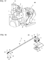
- FIG. 18 is a diagram illustrating a configuration of the medical treatment tool (Example 3).
- FIG. 18 illustrates a state in which the medical treatment tool 1a is detached from the interface 117, and the interface 117 is detached from the drive device 116. Note that, in FIG. 18 , the drape 130 and the sterile adapter 131 are not illustrated.
- FIG. 19 is a diagram illustrating a detailed configuration of a drive device, an interface, and an end portion of the medical treatment tool on the side opposite to the distal end part.
- the drape 130 and the sterile adapter 131 are not illustrated.
- the drive device 116 includes a plurality of transmission members 161, and a plurality of drive sources (not illustrated) that operate the plurality of transmission members 161, respectively.
- the drive device 116 includes two sets of the transmission members 161 and the drive sources for each of the first jaw 22a, the second jaw 22b, and the wrist portion 23 illustrated in FIG. 1 , which means that the drive device 116 includes six sets thereof in total.
- the transmission members 161 is representatively illustrated.
- the interface 117 includes a transmission member 162 that engages with the transmission member 161 of the drive device 116, a housing 170 provided with a lower lid (lid portion) 172 as a release mechanism, and an attachment mechanism (release mechanism) 173 provided in the housing 170.
- the housing 170 is attachable to and detachable from the drive device 116.
- the attachment mechanism 173 includes a first power conversion mechanism 160, a second power conversion mechanism 180, a connecting member 183 that connects the first power conversion mechanism 160 and the second power conversion mechanism 180, an engaging member 184, and a support portion 185.
- the first power conversion mechanism 160 includes a first driving side member 163 and a first driven side member 165, and the first driving side member 163 and the first driven side member 165 are bevel gears.
- the second power conversion mechanism 180 includes a second driving side member 182 and a second driven side member 188, and the second driving side member 182 and the second driven side member 188 are bevel gears.
- the engaging member 184 is, for example, a helical gear.
- the second driven side member 188 of the second power conversion mechanism 180 which is a bevel gear, is provided.
- the first driven side member 165 of the first power conversion mechanism 160 is connected to the second driving side member 182 of the second power conversion mechanism 180 via the connecting member 183.
- the interface 117 further includes a transmission shaft 164 for transmitting the power from the transmission member 162 to the first power conversion mechanism 160.
- the connecting member 183 includes a first connecting portion 183a connected to the first driven side member 165 of the first power conversion mechanism 160 and a second connecting portion 183b connected to the second driving side member 182 of the second power conversion mechanism 180, and a shaft member 186 that connects the first connecting portion 183a and the second connecting portion 183b.
- the first connecting portion 183a is fixed to the first driven side member 165 of the first power conversion mechanism 160.
- the second connecting portion 183b is rotatable about the shaft member 186.
- the support portion 185 supports the rotation shaft of each of the plurality of engagement members 184 and is fixed to the lower lid 172 of the housing 170. Note that in FIG. 19 , one of plural sets is representatively illustrated. Further, in FIG. 19 , a pair of the elongate element 14 and the engagement member 13 is representatively illustrated.
- the engagement member 13, the engaging member 184, the second power conversion mechanism 180, the connecting member 183, and the support portion 185 have the configurations same as those of the engagement member 13, the engaging member 84, the power conversion mechanism 80, and the connecting member 83 and the support portion 85 illustrated in FIG. 7 .
- the drive source in the drive device 116 is operated according to the control signal from the remote control apparatus 4, to rotate the transmission member 161.
- the transmission member 161 transmits the power from the drive source to the transmission member 162.
- the transmission member 162 and the first driving side member 163 of the first power conversion mechanism 160 connected to the transmission member 162 rotate.
- the second driven side member 188 of the second power conversion mechanism 180 meshed with the second driving side member 182 rotates, and at the same time, the engaging member 184 rotates.
- the engagement member 13 engaged with the engaging member 184 and the elongate element 14 connected to the engagement member 13 move along the Z axis.
- first jaw 22a By independently moving the elongate elements 14 along the Z axis, the corresponding first jaw 22a, second jaw 22b, and wrist portion 23 are independently driven.
- FIG. 20 is a diagram illustrating a configuration of the attachment and detachment mechanism between the medical treatment tool and the interface.
- the support portion 185 provided on the lower lid 172 moves, and the engaging member 184 supported by the support portion 185 moves in the direction of the arrow D1.
- the second power conversion mechanism 180 engaged with the engaging member 184 and the second connecting portion 183b connected to the second driving side member 182 of the second power conversion mechanism 180 rotate about the shaft member 186 and move in the direction of the arrow D1.
- the engaging member 184 is separated from the engagement member 13 so that the engagement between the engagement member 184 and the engagement member 13 is released. Therefore, the medical treatment tool 1a can be detached from the interface 117, by pulling out the proximal end part 15 from the insertion hole 175.
- the operator when attaching the medical treatment tool 1a to the interface 117, the operator inserts the proximal end part 15 from the insertion hole 175 so as to position the engagement member 13 inside the interface 117 and then closes the lower lid 172. In other words, the operator rotates the lower lid 172 about the connecting portion 179 in the direction of the arrow D2.
- the support portion 185, the connecting member 183, the second power conversion mechanism 180, and the engaging member 184 move so as to be in the state illustrated in FIG. 19 , and the engaging member 184 and the engagement member 13 engage with each other.
- the medical treatment tool 1a can be attached to the interface 117.
- the attachment and detachment mechanism or method of the medical treatment tool 1a and the interface 117 according to the third embodiment the attachment and detachment mechanism or method described in any one of the first to fourth modifications of the first embodiment may be adopted.
- FIG. 21 is a diagram illustrating an example of arrangement of six engagement members.
- FIG. 21 illustrates a cross section of the proximal end part 15 of the medical treatment tool 1a orthogonal to the longitudinal direction thereof.
- the six sets are arranged in such a manner that two linear rows connecting three sets are lined up.
- the six drive sources 81 are also arranged in such a manner that two linear rows connecting three drive sources 81 are lined up.
- a pressing member located above the housing 70 and a pressing member located below the housing 70 are provided, for example.
- a surgical system may be configured to adopt both of the method for attaching and detaching the medical treatment tool 1a by opening and closing the lower lid 72 according to the first and second modifications of the first embodiment, and the method for attaching and detaching the medical treatment tool 1a without the lower lid 72 according to the third modification of the first embodiment.
- the medical treatment tool 1a can be attached and detached by the other method, so that the resistance to failure can be improved.
- the power conversion mechanisms 80, 180 above-described and the coupling mechanism using the connecting member 83 for power transmission above-described are examples, and a mechanism employing an additional member or a mechanism having an equivalent function may be used.
Landscapes
- Engineering & Computer Science (AREA)
- Robotics (AREA)
- Health & Medical Sciences (AREA)
- Life Sciences & Earth Sciences (AREA)
- Surgery (AREA)
- Mechanical Engineering (AREA)
- Heart & Thoracic Surgery (AREA)
- Biomedical Technology (AREA)
- Nuclear Medicine, Radiotherapy & Molecular Imaging (AREA)
- Medical Informatics (AREA)
- Molecular Biology (AREA)
- Animal Behavior & Ethology (AREA)
- General Health & Medical Sciences (AREA)
- Public Health (AREA)
- Veterinary Medicine (AREA)
- Manipulator (AREA)
- Surgical Instruments (AREA)
Applications Claiming Priority (2)
| Application Number | Priority Date | Filing Date | Title |
|---|---|---|---|
| JP2017252805 | 2017-12-28 | ||
| PCT/JP2018/044224 WO2019130984A1 (ja) | 2017-12-28 | 2018-11-30 | 手術器具、被取付装置、医療用処置具、手術ロボットおよび遠隔手術システム |
Publications (2)
| Publication Number | Publication Date |
|---|---|
| EP3733109A1 true EP3733109A1 (de) | 2020-11-04 |
| EP3733109A4 EP3733109A4 (de) | 2021-01-27 |
Family
ID=67067092
Family Applications (1)
| Application Number | Title | Priority Date | Filing Date |
|---|---|---|---|
| EP18895295.6A Withdrawn EP3733109A4 (de) | 2017-12-28 | 2018-11-30 | Chirurgisches instrument, befestigte vorrichtung, medizinisches behandlungswerkzeug, chirurgischer roboter und ferngesteuertes chirurgisches system |
Country Status (4)
| Country | Link |
|---|---|
| US (1) | US20200323598A1 (de) |
| EP (1) | EP3733109A4 (de) |
| JP (1) | JP6907340B2 (de) |
| WO (1) | WO2019130984A1 (de) |
Families Citing this family (1)
| Publication number | Priority date | Publication date | Assignee | Title |
|---|---|---|---|---|
| CN113017689B (zh) * | 2021-03-03 | 2022-04-01 | 北京理工大学 | 一种柔体臂装置及其控制方法 |
Family Cites Families (10)
| Publication number | Priority date | Publication date | Assignee | Title |
|---|---|---|---|---|
| US6331181B1 (en) | 1998-12-08 | 2001-12-18 | Intuitive Surgical, Inc. | Surgical robotic tools, data architecture, and use |
| US9386983B2 (en) * | 2008-09-23 | 2016-07-12 | Ethicon Endo-Surgery, Llc | Robotically-controlled motorized surgical instrument |
| SG10201501658VA (en) | 2010-03-10 | 2015-04-29 | Ricoh Co Ltd | Toner container and image forming device |
| US20140001231A1 (en) * | 2012-06-28 | 2014-01-02 | Ethicon Endo-Surgery, Inc. | Firing system lockout arrangements for surgical instruments |
| US9561038B2 (en) | 2012-06-28 | 2017-02-07 | Ethicon Endo-Surgery, Llc | Interchangeable clip applier |
| EP2942027B1 (de) * | 2012-07-03 | 2019-06-26 | KUKA Deutschland GmbH | Chirurgische instrumentenanordnung und antriebsstranganordnung für ein, insbesondere robotergeführtes, chirurgisches instrument und chirurgisches instrument |
| WO2014157001A1 (ja) * | 2013-03-26 | 2014-10-02 | オリンパス株式会社 | 処置具 |
| JP6081309B2 (ja) * | 2013-07-24 | 2017-02-15 | オリンパス株式会社 | 医療用マニピュレータ |
| CN109247987B (zh) * | 2013-08-15 | 2021-07-23 | 直观外科手术操作公司 | 预加载外科手术器械接口 |
| JP6157792B2 (ja) * | 2015-06-01 | 2017-07-05 | オリンパス株式会社 | 医療用マニピュレータ |
-
2018
- 2018-11-30 EP EP18895295.6A patent/EP3733109A4/de not_active Withdrawn
- 2018-11-30 WO PCT/JP2018/044224 patent/WO2019130984A1/ja not_active Ceased
- 2018-11-30 JP JP2019562892A patent/JP6907340B2/ja not_active Expired - Fee Related
-
2020
- 2020-06-25 US US16/911,409 patent/US20200323598A1/en not_active Abandoned
Also Published As
| Publication number | Publication date |
|---|---|
| JPWO2019130984A1 (ja) | 2020-12-17 |
| EP3733109A4 (de) | 2021-01-27 |
| JP6907340B2 (ja) | 2021-07-21 |
| WO2019130984A1 (ja) | 2019-07-04 |
| US20200323598A1 (en) | 2020-10-15 |
Similar Documents
| Publication | Publication Date | Title |
|---|---|---|
| US12433701B2 (en) | Geared grip actuation for medical instruments | |
| CN111888012B (zh) | 手术器械平台 | |
| EP2286756B1 (de) | Chirurgische Manipulationsmittel | |
| EP1176921B1 (de) | Chirurgisches instrument | |
| US8828046B2 (en) | Laparoscopic device with distal handle | |
| JP5898105B2 (ja) | 多構成テレプレゼンスシステムおよびその方法 | |
| EP2919674B1 (de) | Systeme für ein chirurgisches instrument mit doppelsteuerung | |
| JP2020528288A (ja) | 外科手術装置 | |
| KR20170129968A (ko) | 독립적으로 회전하는 부재 내의 병렬 구동 샤프트들을 위한 모터 연접부 | |
| JP6858954B2 (ja) | 内視鏡システム | |
| US11931026B2 (en) | Staple cartridge replacement | |
| US20190216557A1 (en) | Treatment tool unit, medical treatment tool, and surgical system | |
| KR20170125174A (ko) | 최소침습수술용 로봇장치 | |
| JPH07328024A (ja) | 医療用マニピュレータ装置 | |
| JPH08224247A (ja) | 医療用マニピュレータ | |
| EP2005906A2 (de) | Chirurgische Werkzeuge und Betriebssystem | |
| US20200323598A1 (en) | Surgical instrument and surgical robot | |
| US20250268673A1 (en) | Robotic surgical instruments | |
| EP2982319A1 (de) | Medizinischer manipulator | |
| CN116322552A (zh) | 接口连接手术机器人臂和器械 | |
| CN221865966U (zh) | 手术器械和医疗系统 | |
| JP4331490B2 (ja) | 外科用処置具 | |
| CN122005103A (zh) | 一种用于消化内镜的微型高灵活度主从式机械臂操作系统 | |
| JP2004255080A (ja) | 外科用処置具 | |
| CN120203795A (zh) | 手术器械和医疗系统 |
Legal Events
| Date | Code | Title | Description |
|---|---|---|---|
| STAA | Information on the status of an ep patent application or granted ep patent |
Free format text: STATUS: THE INTERNATIONAL PUBLICATION HAS BEEN MADE |
|
| PUAI | Public reference made under article 153(3) epc to a published international application that has entered the european phase |
Free format text: ORIGINAL CODE: 0009012 |
|
| STAA | Information on the status of an ep patent application or granted ep patent |
Free format text: STATUS: REQUEST FOR EXAMINATION WAS MADE |
|
| 17P | Request for examination filed |
Effective date: 20200619 |
|
| AK | Designated contracting states |
Kind code of ref document: A1 Designated state(s): AL AT BE BG CH CY CZ DE DK EE ES FI FR GB GR HR HU IE IS IT LI LT LU LV MC MK MT NL NO PL PT RO RS SE SI SK SM TR |
|
| AX | Request for extension of the european patent |
Extension state: BA ME |
|
| A4 | Supplementary search report drawn up and despatched |
Effective date: 20210112 |
|
| RIC1 | Information provided on ipc code assigned before grant |
Ipc: A61B 34/37 20160101ALI20201221BHEP Ipc: A61B 17/3201 20060101ALI20201221BHEP Ipc: A61B 17/00 20060101ALN20201221BHEP Ipc: B25J 18/06 20060101ALI20201221BHEP Ipc: A61B 17/062 20060101ALI20201221BHEP Ipc: A61B 34/30 20160101AFI20201221BHEP Ipc: A61B 34/35 20160101ALI20201221BHEP Ipc: A61B 17/28 20060101ALI20201221BHEP |
|
| DAV | Request for validation of the european patent (deleted) | ||
| DAX | Request for extension of the european patent (deleted) | ||
| STAA | Information on the status of an ep patent application or granted ep patent |
Free format text: STATUS: THE APPLICATION HAS BEEN WITHDRAWN |
|
| 18W | Application withdrawn |
Effective date: 20210827 |