EP3733119A1 - Filtre - Google Patents
Filtre Download PDFInfo
- Publication number
- EP3733119A1 EP3733119A1 EP18897532.0A EP18897532A EP3733119A1 EP 3733119 A1 EP3733119 A1 EP 3733119A1 EP 18897532 A EP18897532 A EP 18897532A EP 3733119 A1 EP3733119 A1 EP 3733119A1
- Authority
- EP
- European Patent Office
- Prior art keywords
- filter
- segment
- support
- center axis
- longitudinal center
- Prior art date
- Legal status (The legal status is an assumption and is not a legal conclusion. Google has not performed a legal analysis and makes no representation as to the accuracy of the status listed.)
- Granted
Links
Images


Classifications
-
- A—HUMAN NECESSITIES
- A61—MEDICAL OR VETERINARY SCIENCE; HYGIENE
- A61F—FILTERS IMPLANTABLE INTO BLOOD VESSELS; PROSTHESES; DEVICES PROVIDING PATENCY TO, OR PREVENTING COLLAPSING OF, TUBULAR STRUCTURES OF THE BODY, e.g. STENTS; ORTHOPAEDIC, NURSING OR CONTRACEPTIVE DEVICES; FOMENTATION; TREATMENT OR PROTECTION OF EYES OR EARS; BANDAGES, DRESSINGS OR ABSORBENT PADS; FIRST-AID KITS
- A61F2/00—Filters implantable into blood vessels; Prostheses, i.e. artificial substitutes or replacements for parts of the body; Appliances for connecting them with the body; Devices providing patency to, or preventing collapsing of, tubular structures of the body, e.g. stents
- A61F2/01—Filters implantable into blood vessels
- A61F2/012—Multiple filtering units
-
- A—HUMAN NECESSITIES
- A61—MEDICAL OR VETERINARY SCIENCE; HYGIENE
- A61F—FILTERS IMPLANTABLE INTO BLOOD VESSELS; PROSTHESES; DEVICES PROVIDING PATENCY TO, OR PREVENTING COLLAPSING OF, TUBULAR STRUCTURES OF THE BODY, e.g. STENTS; ORTHOPAEDIC, NURSING OR CONTRACEPTIVE DEVICES; FOMENTATION; TREATMENT OR PROTECTION OF EYES OR EARS; BANDAGES, DRESSINGS OR ABSORBENT PADS; FIRST-AID KITS
- A61F2/00—Filters implantable into blood vessels; Prostheses, i.e. artificial substitutes or replacements for parts of the body; Appliances for connecting them with the body; Devices providing patency to, or preventing collapsing of, tubular structures of the body, e.g. stents
- A61F2/01—Filters implantable into blood vessels
- A61F2/0108—Both ends closed, i.e. legs gathered at both ends
-
- A—HUMAN NECESSITIES
- A61—MEDICAL OR VETERINARY SCIENCE; HYGIENE
- A61F—FILTERS IMPLANTABLE INTO BLOOD VESSELS; PROSTHESES; DEVICES PROVIDING PATENCY TO, OR PREVENTING COLLAPSING OF, TUBULAR STRUCTURES OF THE BODY, e.g. STENTS; ORTHOPAEDIC, NURSING OR CONTRACEPTIVE DEVICES; FOMENTATION; TREATMENT OR PROTECTION OF EYES OR EARS; BANDAGES, DRESSINGS OR ABSORBENT PADS; FIRST-AID KITS
- A61F2/00—Filters implantable into blood vessels; Prostheses, i.e. artificial substitutes or replacements for parts of the body; Appliances for connecting them with the body; Devices providing patency to, or preventing collapsing of, tubular structures of the body, e.g. stents
- A61F2/01—Filters implantable into blood vessels
- A61F2/0103—With centering means
-
- A—HUMAN NECESSITIES
- A61—MEDICAL OR VETERINARY SCIENCE; HYGIENE
- A61F—FILTERS IMPLANTABLE INTO BLOOD VESSELS; PROSTHESES; DEVICES PROVIDING PATENCY TO, OR PREVENTING COLLAPSING OF, TUBULAR STRUCTURES OF THE BODY, e.g. STENTS; ORTHOPAEDIC, NURSING OR CONTRACEPTIVE DEVICES; FOMENTATION; TREATMENT OR PROTECTION OF EYES OR EARS; BANDAGES, DRESSINGS OR ABSORBENT PADS; FIRST-AID KITS
- A61F2/00—Filters implantable into blood vessels; Prostheses, i.e. artificial substitutes or replacements for parts of the body; Appliances for connecting them with the body; Devices providing patency to, or preventing collapsing of, tubular structures of the body, e.g. stents
- A61F2/01—Filters implantable into blood vessels
- A61F2/011—Instruments for their placement or removal
-
- A—HUMAN NECESSITIES
- A61—MEDICAL OR VETERINARY SCIENCE; HYGIENE
- A61F—FILTERS IMPLANTABLE INTO BLOOD VESSELS; PROSTHESES; DEVICES PROVIDING PATENCY TO, OR PREVENTING COLLAPSING OF, TUBULAR STRUCTURES OF THE BODY, e.g. STENTS; ORTHOPAEDIC, NURSING OR CONTRACEPTIVE DEVICES; FOMENTATION; TREATMENT OR PROTECTION OF EYES OR EARS; BANDAGES, DRESSINGS OR ABSORBENT PADS; FIRST-AID KITS
- A61F2/00—Filters implantable into blood vessels; Prostheses, i.e. artificial substitutes or replacements for parts of the body; Appliances for connecting them with the body; Devices providing patency to, or preventing collapsing of, tubular structures of the body, e.g. stents
- A61F2/01—Filters implantable into blood vessels
- A61F2002/016—Filters implantable into blood vessels made from wire-like elements
-
- A—HUMAN NECESSITIES
- A61—MEDICAL OR VETERINARY SCIENCE; HYGIENE
- A61F—FILTERS IMPLANTABLE INTO BLOOD VESSELS; PROSTHESES; DEVICES PROVIDING PATENCY TO, OR PREVENTING COLLAPSING OF, TUBULAR STRUCTURES OF THE BODY, e.g. STENTS; ORTHOPAEDIC, NURSING OR CONTRACEPTIVE DEVICES; FOMENTATION; TREATMENT OR PROTECTION OF EYES OR EARS; BANDAGES, DRESSINGS OR ABSORBENT PADS; FIRST-AID KITS
- A61F2220/00—Fixations or connections for prostheses classified in groups A61F2/00 - A61F2/26 or A61F2/82 or A61F9/00 or A61F11/00 or subgroups thereof
- A61F2220/0008—Fixation appliances for connecting prostheses to the body
-
- A—HUMAN NECESSITIES
- A61—MEDICAL OR VETERINARY SCIENCE; HYGIENE
- A61F—FILTERS IMPLANTABLE INTO BLOOD VESSELS; PROSTHESES; DEVICES PROVIDING PATENCY TO, OR PREVENTING COLLAPSING OF, TUBULAR STRUCTURES OF THE BODY, e.g. STENTS; ORTHOPAEDIC, NURSING OR CONTRACEPTIVE DEVICES; FOMENTATION; TREATMENT OR PROTECTION OF EYES OR EARS; BANDAGES, DRESSINGS OR ABSORBENT PADS; FIRST-AID KITS
- A61F2230/00—Geometry of prostheses classified in groups A61F2/00 - A61F2/26 or A61F2/82 or A61F9/00 or A61F11/00 or subgroups thereof
- A61F2230/0002—Two-dimensional shapes, e.g. cross-sections
- A61F2230/0028—Shapes in the form of latin or greek characters
- A61F2230/006—Y-shaped
-
- A—HUMAN NECESSITIES
- A61—MEDICAL OR VETERINARY SCIENCE; HYGIENE
- A61F—FILTERS IMPLANTABLE INTO BLOOD VESSELS; PROSTHESES; DEVICES PROVIDING PATENCY TO, OR PREVENTING COLLAPSING OF, TUBULAR STRUCTURES OF THE BODY, e.g. STENTS; ORTHOPAEDIC, NURSING OR CONTRACEPTIVE DEVICES; FOMENTATION; TREATMENT OR PROTECTION OF EYES OR EARS; BANDAGES, DRESSINGS OR ABSORBENT PADS; FIRST-AID KITS
- A61F2250/00—Special features of prostheses classified in groups A61F2/00 - A61F2/26 or A61F2/82 or A61F9/00 or A61F11/00 or subgroups thereof
- A61F2250/0014—Special features of prostheses classified in groups A61F2/00 - A61F2/26 or A61F2/82 or A61F9/00 or A61F11/00 or subgroups thereof having different values of a given property or geometrical feature, e.g. mechanical property or material property, at different locations within the same prosthesis
- A61F2250/0029—Special features of prostheses classified in groups A61F2/00 - A61F2/26 or A61F2/82 or A61F9/00 or A61F11/00 or subgroups thereof having different values of a given property or geometrical feature, e.g. mechanical property or material property, at different locations within the same prosthesis differing in bending or flexure capacity
-
- A—HUMAN NECESSITIES
- A61—MEDICAL OR VETERINARY SCIENCE; HYGIENE
- A61F—FILTERS IMPLANTABLE INTO BLOOD VESSELS; PROSTHESES; DEVICES PROVIDING PATENCY TO, OR PREVENTING COLLAPSING OF, TUBULAR STRUCTURES OF THE BODY, e.g. STENTS; ORTHOPAEDIC, NURSING OR CONTRACEPTIVE DEVICES; FOMENTATION; TREATMENT OR PROTECTION OF EYES OR EARS; BANDAGES, DRESSINGS OR ABSORBENT PADS; FIRST-AID KITS
- A61F2250/00—Special features of prostheses classified in groups A61F2/00 - A61F2/26 or A61F2/82 or A61F9/00 or A61F11/00 or subgroups thereof
- A61F2250/0014—Special features of prostheses classified in groups A61F2/00 - A61F2/26 or A61F2/82 or A61F9/00 or A61F11/00 or subgroups thereof having different values of a given property or geometrical feature, e.g. mechanical property or material property, at different locations within the same prosthesis
- A61F2250/0037—Special features of prostheses classified in groups A61F2/00 - A61F2/26 or A61F2/82 or A61F9/00 or A61F11/00 or subgroups thereof having different values of a given property or geometrical feature, e.g. mechanical property or material property, at different locations within the same prosthesis differing in height or in length
Definitions
- the invention relates to an implanted medical instrument, and in particular to a filter.
- Pulmonary embolism is a common disease, with high mortality. According to statistics, the mortality of PE without treatment is 20%-30% ,and the new cases account for 0.2% of the population every year. There are about 2.7 million new patients per year calculated from 1.35 billion population in China.
- Vena cava filter (hereinafter referred to as filter) has been clinically proven to reduce the incidence of pulmonary embolism. Permanent implantation of the filter carries the following risks: long-term contact of the filter with blood and vascular endothelium may lead to protein adsorption, platelet adhesion, and ultimately thrombosis resulting in venous blockage, or pulmonary embolism recurrence; for long-term implantation in vivo, there may be risks of filter deformation, tilt, shift, fracture, and even penetration through blood vessels. Therefore, it is clinically recommended to use a temporary filter which is implanted during the acute phase of a patient's deep venous thrombosis and then removed after the acute phase when the risk of thrombosis shedding is reduced.
- a support rod of the filter will be crawled and wrapped by endothelial cells to varying degrees, which may damage the intima of blood vessels during the removal, therefore, it is necessary to provide a filter which can be removed conveniently without damaging the intima of the blood vessels.
- a filter comprising a main body part.
- the main body part includes a heart-proximal end, a plurality of connecting segments and a first filter mesh connected between the heart-proximal end and the plurality of connecting segments.
- One end of the connecting segments that is connected to the first filter mesh is bent towards one side of a longitudinal center axis of the filter to form a bending part, and a vertical distance between the proximal end of the bending part and the longitudinal center axis of the filter is less than a vertical distance between the distal end of the bending part and the longitudinal center axis of the filter.
- a filter comprising a main body part and a plurality of support parts.
- the support parts includes at least one support which includes a guide segment connected to the main body part of the connector.
- an included angle between a connecting line between both ends of the guide segment and the longitudinal center axis of the filter is 20°-85°, and the ratio of a height of the support in the radial direction of the filter to the maximum distance of the support to the longitudinal center axis of the filter is 1/8-1/3.
- the disclosure is provided with the bending part by bending an end of the connecting segments that is connected to the first filter mesh towards one side of the longitudial center axis of the filter, allowing a surface of the first filter mesh to be away from a surface of a blood vessel so as to avoid contacting an inner wall of the blood vessel when the first filter mesh bulge, and further the bending part can bear a portion of stress, thereby preventing stress from concentrating on a connection between the first filter mesh and the connecting segments.
- the bending part provided on the connecting segments can also increase the length of the connecting segments, delay the time for the endothelial tissue to climb to the first filter mesh, and increase the climbing difficulty of endothelial cells.
- the section of the filter that is closer to the heart after implantation in a human body is called the heart-proximal end, and the end that is farther from the heart is called the heart-distal end.
- one of the preferred embodiments of the disclosure provides a filter 100 for implantation into a lumen of a human body to capture thrombus in the lumen, include a main body part 1, a plurality of support parts 2 connected to the main body part 1, at least one mooring anchor 3 connected to the support parts 2, and a recovery hook 4 provided on one end of the main body part 1.
- the main body part 1 includes a heart-proximal end 11, a heart-distal end 12, and a connector 13 provided between the heart-proximal end 11 and the heart-distal end 12.
- the connector 13 includes a first filter mesh 131, a second filter mesh 133, and a plurality of connecting segments 132 between the first filter mesh 131 and the second filter mesh 133, and the plurality of connecting segments 132 are equally spaced along the circumferential direction of the connector 13.
- the first filter mesh 131 is a mesh structure , and the first filter mesh 131 is extending from one end of the plurality of connecting segments 132 towards a direction away from the connecting segments 132, and the first filter mesh 131 is converging to the heart-proximal end 11, and the second filter mesh 133 is a mesh structure , and the second filter mesh 133 is extending from the other end of the plurality of connecting segments 132 towards a direction away from the connecting segments 132, and the second filter mesh 133 is converging to the heart-distal end 12.
- the first filter mesh 131 is composed of a set of first Y-shaped rods 1311 equally spaced along the circumferential direction of the connector 13, the number of the first Y-shaped rods 1311 corresponding to the number of the connecting segments 132, each of the first Y-shaped rods 1311 comprising a first main branch segment 1312 and two first branch segments 1313 separated by one end of the first main branch segment 1312.
- the first main branch segment 1313 is connected between the heart-proximal end 11 and the two first branch segments 1313, and the ends, away from the heart-proximal end 11, of two adjacent first branch segments 1313 of two adjacent first Y-shaped rods 1311 converge on one connecting segment 132.
- the end, close to the heart-proximal end 11, of the first main branch segment 1312 is the proximal end of the first filter mesh 131, and the end, away from the heart-proximal end 11, of each first branch segment 1313 of the first Y-shaped rods 1311 is the distal end of the first filter mesh 131.
- the second filter mesh 133 is composed of a set of second Y-shaped rods 1331 equally spaced along the circumferential direction of the connector 13, the number of the second Y-shaped rods 1331 being half of the number of the connecting segments 132.
- Each second Y-shaped rods 1331 includes a second main branch segment 1332 and two second branch segments 1333 separated by one end of the second main branch segment 1332.
- the second main branch segment 1333 is connected between the heart-distal end 12 and the two second branch segments 133, and each second branch segments 1333 of the second Y-shaped rods 1331 is connected to one connecting segment 132.
- each second branch segment 1333 of the second Y-shaped rods 1331 is the proximal end of the second filter mesh 133.
- the main body part 1 of the filter 100 has an asymmetric structure as a whole, and the number of the first Y-shaped rods 1311 is twice the number of the second Y-shaped rods 1331, that is, the rod density of the first filter mesh 131 is greater than the rod density of the second filter mesh 133.
- the connector 13 is made of a material having a shape memory function, such as nitinol, and is deformed to an expanded state after the filter 100 is conveyed to the lumen of a human body and released from a conveying sheath of a conveyor.
- thrombus blood flow flows from the heart-distal end 12 to the heart-proximal end 11, thrombus first passes through a gap formed by the second Y-shaped rods 1331 with a smaller rod density, enters the inside of the filter 100, and is then blocked by the first Y-shaped rods 1311 with a larger rod density to be retained inside the filter 100, thereby achieving the filtration of thrombus.
- the recovery hook 4 can be selectively provided at the heart-proximal end 11 or the heart-distal end 12, and the recovery hook 4 can be in a hook body or a threaded structure and the like and is used for removing the filter 100 after thrombus filtration.
- one end of the connecting segments 132 that is connected to the first filter mesh 131 is bent towards one side of the longitudinal center axis of the filter 100 to form a bending part 1321.
- a vertical distance h1 between the proximal end of bending part 1321 and the longitudinal center axis of the filter 100 is less than a vertical distance h2 between the distal end of the bending part 1321 and the longitudinal center axis of the filter 100.
- the proximal end of the bending part 1321 herein refers to the end of the bending part 1321 that is connected to the first filter mesh 131
- the distal end of the bending part 1321 refers to the end of the bending part 1321 that is away from the first filter mesh 131.
- the lumen wall When the filter 100 is implanted into the lumen, the lumen wall has a radially inward pressure on the filter 100 causing the connecting segments 132 to move towards one side of the longitudinal center axis of the filter 100, and the portion of the first filter mesh 131 that is close to the connecting segments 132 will bulge upward against the inner wall of the blood vessel under a reaction force, causing vascular endothelium to climb to the bulge, which is detrimental to the recovery of the filter 100. Further, when the first filter mesh 131 bulges upward, an included angle between the two first branch segments 1313 converging on one connecting segment 132 becomes large, resulting in stress concentration on a connection between the two first branch segments 1313 and the connecting segments 132.
- the pressure acting on the support parts 2 by the lumen wall is an alternating stress, and under the action of the alternating stress, the two first branch segments 1313 of the first filter mesh 131 converging on one connecting segment 132 are prone to fatigue fracture after a long time of operation.
- the bending part 1321 is provided at one end, connected to the first filter mesh 131, of the connecting segments 132, allowing a surface of the first filter mesh 131 to be away from a surface of the blood vessel so as to avoid contacting an inner wall of the blood vessel when the first filter mesh 131 bulges, and the lowest point of the bending part 1321 can pull the distal end of the first filter mesh 131 to move towards one side of the longitudinal center axis of the filter 100 so as to transfer the bulging position on the first filter mesh 131 from the distal position of the first filter mesh 131 to the middle or proximal position of the first filter mesh 131, thereby preventing stress from concentrating on a connection of the two first branch segments 1313 and the connecting segments 132.
- the lowest point of the bending part 1321 refers to the point on the bending part 1321 that is the shortest perpendicular distance from the longitudinal center axis of the filter 100. Further, by providing the bending part 1321 at the end where the connecting segments 132 are connected to the first filter mesh 131, the bending part 1321 can bear a portion of the stress and reduce the stress concentrated on the connection between the two first branch segments 1313 and the connecting segments 132.
- the bending part 1321 provided on the connecting segments 132 can also increase the length of the connecting segments 132, delay the time for the endothelial tissue to climb to the first filter mesh 131, and increase the difficulty for endothelial cells to climb to the first filter mesh 131.
- the height difference between the vertical distance h1 between the proximal end of the bending part 1321 and the longitudinal center axis of the filter 100 and the vertical distance h2 between the distal end of the bending part 1321 and the longitudinal center axis of the filter 100 is 1mm-5mm, preferably 2mm-3mm.
- the shorter a distance L2 between the proximal end of the bending part 1321 and the distal end of the bending part 1321 in a direction of the longitudinal center axis of the filter 100 is, the greater an included angle between a connecting line between the proximal end of the bending part 1321 and the distal end of the bending part 1321 and the longitudinal center axis of the filter 100 is, which may affect the compliance of the filter 100 into and out of a sheath, but when L2 is too long, it may result in poor stability and easy tilting of the filter 100.
- the ratio of the distance L2 between the proximal end of the bending part 1321 and the distal end of the bending part 1321 in the direction of the longitudinal center axis of the filter 100 to the distance L1 between both ends of the connecting segments 132 in the direction of the longitudinal center axis of the filter 100 is 1/20-3/5, preferably 1/10-1/3.
- the connecting segments 132 includes the bending part 1321 and a connecting part 1322 which are connected, and in this embodiment the connecting part 1322 is distributed substantially parallel to the longitudinal center axis of the filter 100.
- the bending part 1321 includes a first bending segment 1341 and a second bending segment 1342 which are connected, the first bending segment 1341 being connected to the distal end of the first filter mesh 131, the second bending segment 1342 being connected to the proximal end of the connecting part 1322.
- the first bending segment 1341 is smoothly connected to the first filter mesh 131, the first bending segment 1341 to the second bending segment 1342, and the second bending segment 1342 to the connecting part 1322.
- the ratio of the distance L3 between both ends of the first bending segment 1341 in the direction of the longitudinal center axis of the filter 100 to the distance L2 between both ends of the bending part 1321 in the direction of the longitudinal center axis of the filter 100 is 1/5-3/5, preferably 1/4-1/3.
- the disclosure does not limit the particular configuration of the bending part 1321, and in other embodiments, the first bending segment 1341 and the second bending segment 1342 may be straight segments, curved segments, or hybrid segments in which the straight segments are connected to the curved segments.
- the lowest point of the bending part 1321 may be at the proximal end of the bending part 1321 or at the middle of the bending part 1321.
- the bending part 1321 includes three or more bending segments with a smooth connection between the three or more bending segments.
- the first bending segment 1341 is a straight segment parallel to the direction of the longitudinal center axis of the filter 100 to facilitate processing.
- the connecting part 1322 may be a straight segment, a curved segment, or a combination of straight and curve segments disposed obliquely with respect to the direction of the longitudinal center axis of the filter 100.
- the connecting part 1322 is provided with a concave structure 1323 that is designed to keep most of the surface of the connecting segments 132 away from the surface of the blood vessel, thereby further increasing the climbing difficulty of endothelial cells.
- a vertical distance h3 between the distal end of the connecting part 1322 and the longitudinal center axis of the filter 100 is not less than the vertical distance h1 between the proximal end of the bending part 1321 and the longitudinal center axis of the filter 100, and is not greater than the vertical distance h2 between the distal end of the bending part 1321 and the longitudinal center axis of the filter 100.
- the distal end of the connecting part 1322 herein refers to the end of the connecting part 1322 that is connected to the second filter mesh 133.
- the vertical distance h3 between the distal end of the connecting part 1322 and the longitudinal center axis of the filter 100 is equal to the vertical distance h2 between the distal end of the bending part 1321 and the longitudinal center axis of the filter 100.
- the second branch segments 1333 of the second filter mesh 133 are provided with a flexible part 1334 bent towards one side of the longitudinal center axis of the filter 100, and a bending strength of the second filter mesh 133 at the flexible part 1334 is lower than a bending strength of the second filter mesh 133 at the remaining area except the flexible part 1334.
- the flexible part 1334 When the filter 100 is radially extruded, the flexible part 1334 is bent and deformed towards one side of the longitudinal center axis of the filter 100, allowing a surface of the second filter mesh 133 to be away from a surface of the blood vessel so as to avoid contacting an inner wall of the blood vessel when the second filter screen 133 bulges, delay the time for the endothelial tissue to climb to the second filter mesh 133, and increase the climbing difficulty for the endothelial cells to climb to the second filter mesh 133.
- each support part 2 is connected to the main body part 1, and the other end thereof extends towards one side of the heart-proximal end 11.
- the support parts 2 are directly contacted with the inner wall of the lumen, and the main body part 1 is separated from the inner wall of the lumen, so that when the filter 100 is removed, the support parts 2 only need to be separated from the lumen wall. Since the contact surface between the support parts 2 and the lumen wall is small, the stimulation to the lumen wall can be reduced to facilitate the removal of the filter 100. Further, by providing the support parts 2, it is possible to further delay the time for the endothelial tissue to climb to the first filter mesh 131 and the connecting segments 132, and to extend the recovery time of the filter.
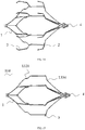
- FIG. 7 is a deformation schematic diagram after the filter 100 of the embodiment is implanted into a blood vessel, and FIG.
- FIG. 8 is a deformation schematic diagram after the filter 100 not provided with the bending part 1321 and the flexible part 1334 is implanted into a blood vessel.
- the bending part 1321 and the flexible part 1334 deform so as to make the support parts 2 keep straight deformation and prevent a connection between the support parts 2 and the connecting segments 132 from bulging to contact the vessel wall, so that the filter is more stable in the blood vessel, while the connection between the support parts 2 and the connecting segments 132 in FIG. 8 is prone to bulge to contact the vessel wall.
- the disclosure does not limit the specific location of the support parts 2 on the connecting segments 132, and as shown in FIG. 9 , an intersection point 20 of the support parts 2 and the connecting segments 132 is located on the connecting part 1322; alternatively, as shown in FIG. 10 , the intersection point 20 of the support parts 2 and the connecting segments 132 is located in the bending part 1321. It will also be appreciated that the disclosure does not limit the specific number of the support parts 2 on each connecting segment 132 to which one or more support parts 2 may be connected. As shown in FIG. 11 , only one support part 2 is connected to each connecting segment 132, and the support parts 2 on two adjacent connecting segments 132 are staggered.
- each support part 2 includes at least one support 21.
- each support 21 includes a guide segment 211 and a support segment 212 connected to the guide segment 211, and the guide segment 211 is smoothly connected to the support segment 212.
- One end of the guide segment 211 is connected to the connecting segments 132, the other end of the guide segment 211 extends radially outward in a direction away from the recovery hook 4, and under the natural release state of the filter, an included angle a between a connecting line between both ends of the guide segment 211 and the longitudinal center axis of the filter 100 is 20°-85°.
- the ratio of a height m1 of the support 21 in the radial direction of the filter to a maximum distance m2 between the support 21 and the longitudinal center axis of the filter 100 is 1/8-1/3.
- the height m1 of the support 21 in the radial direction of the filter herein refers to the distance between the highest point of the support 21 and the intersection point 20 of the support 21 and the connecting segments 132 in the radial direction of the filter.
- the outer diameter of the filter 100 is specified, if the height m1 of the support 21 in the radial direction of the filter 100 is too large, not only is the support 21 easily bent with a poor support effect, but also the corresponding outer diameter of the main body part 1 is smaller, affecting the thrombus filtration effect of the filter 100; if the height m1 of the support 21 in the radial direction of the filter 100 is too small, the endothelial tissue easily climbs to the main body part 1, which is detrimental to the recovery of the filter 100.
- the height m1 of the support 21 in the radial direction of the filter 100 is constant, if an included angle a between the connecting line between both ends of the guide segment 211 and the longitudinal center axis of the filter 100 is too large, it may affect the compliance of the filter 100 into and out of the sheath, and if the included angle a is too small, it may affect the support effect of the support 21.
- the support 21 by adjusting the ratio of the height m1 of the support 21 in the radial direction of the filter 100 to the maximum distance m2 between the support 21 and the longitudinal center axis of the filter 100, and by adjusting the included angle a between the connecting line between both ends of the guide segment 211 and the longitudinal center axis of the filter 100, the support 21 has a better supporting force and the time of endothelial climbing is delayed without affecting the effect of filtering thrombus by the filter 100.
- the included angle a between the connecting line between both ends of the guide segment 211 and the longitudinal center axis of the filter 100 is 30°-60°, and the ratio of the height m1 of the support 21 in the radial direction of the filter to the maximum distance m2 between the support 21 to the longitudinal center axis of the filter 100 is 1/6-5/18.
- one end of the support segment 212 is connected to the guide segment 211, the other end of the support segment 212 extends radially outward in a direction away from the recovery hook 4, and an included angle b between a connecting line between both ends of the support segment 212 and the longitudinal center axis of the filter 100 is 10°-20°, and the ratio of the height m3 of both ends of the guide segment 211 in the radial direction of the filter to the height m1 of the support 21 in the radial direction of the filter 100 is 1/2-5/6.
- the height m3 is constant, if the included angle b is too large, the distance between both ends of the support segment 212 in the direction of the longitudinal center axis of the filter 100 is too short, the contact area between the support segment 212 and the lumen wall is small, causing large stimulation on the lumen wall, and if the included angle b is too small, the support segment 212 moves towards one side of the longitudinal center axis of the filter 100 under the action of the pressure of the lumen wall, so that a connection between the guide segment 211 and the support segment 212 bulges to contact the lumen wall and easily pierce the vessel wall.
- the disclosure does not limit the particular configuration of the support segment 212, and in other embodiments, the support segment 212 may be other configurations. As shown in FIG. 13 , the support segment 212 has a circular arc structure.
- the support 21 may also include a lower folding segment 213 smoothly connected to the support segment 212, and the lower folding section 213 is bent and extends towards one side of a longitudinal centerline of the filter 100. It will be appreciated that when an included angle between the lower folding segment 213 and the longitudinal centerline of the filter 100 is greater, the lower folding segment 213 tends to puncture the vessel wall, and when the included angle between the lower folding segment 213 and the longitudinal centerline of the filter 100 is smaller, the into and out sheath force is affected, therefore the included angle between the lower folding segment 213 and the longitudinal centerline of the filter 100 is preferably 20°-75°. Further, the terminal of the lower folding segment 213 is provided with a spherical part 214 with a smooth outer contour to prevent the support segment 212 from piercing the vessel wall.
- each support part 2 includes a support 21 located on one side of the connecting segments 132. It will be appreciated that in other embodiments, as shown in FIG. 12 , each support part 2 may also include two or more supports 21 connected to each side of the connecting segments 132. It will be appreciated that when two or more supports 21 are provided on each connecting segment 132, the structure of the two or more supports 21 may be the same or different.
- the mooring anchor 3 is provided on the support parts 2, and after the filter 100 is implanted into the lumen, the mooring anchor 3 penetrates into the tissue of the inner wall of the lumen, and functions to fix the filter 100. It will be appreciated that the disclosure does not limit the specific configuration and placement of the mooring anchor 3, and the mooring anchor 3 may be selectively provided on the guide segment 211 or the support segment 212 so long as the mooring anchor 3 can penetrate into the lumen wall tissue after the filter 100 is implanted into the lumen.
- FIG. 14 shows a schematic diagram of a structure in which no mooring anchor is provided on the support of the filter.
- each connecting segment 132 two support parts are provided on each connecting segment 132, the two support parts include a first support part connected to the proximal end region of the connecting segments 132, and a second support part connected to the distal end region of the connecting segments 132, and the mooring anchor 3 is provided on the second support part.
- a distance between the intersection point 20 of the first support part and the connecting segments 132 and the distal end of the bending part 1321 in the direction of the longitudinal center axis of the filter is 0.3mm-3mm, and the intersection point of the second support part and the connecting segments 132 is located at the distal end of the connecting segments 132.
- the intersection point 20 of the first support part and the connecting segments 132 can be located between the bending part 1321 and the concave structure 1323.
- the filter according to a second preferred embodiment of the disclosure differs from the first embodiment in that the filter 1 is not provided with the support parts 2, and the mooring anchor 3 is provided directly on the connector 13.
Landscapes
- Health & Medical Sciences (AREA)
- Cardiology (AREA)
- Oral & Maxillofacial Surgery (AREA)
- Transplantation (AREA)
- Engineering & Computer Science (AREA)
- Biomedical Technology (AREA)
- Heart & Thoracic Surgery (AREA)
- Vascular Medicine (AREA)
- Life Sciences & Earth Sciences (AREA)
- Animal Behavior & Ethology (AREA)
- General Health & Medical Sciences (AREA)
- Public Health (AREA)
- Veterinary Medicine (AREA)
- Surgical Instruments (AREA)
- Prostheses (AREA)
Applications Claiming Priority (3)
| Application Number | Priority Date | Filing Date | Title |
|---|---|---|---|
| CN201711437874.3A CN109953839B (zh) | 2017-12-26 | 2017-12-26 | 滤器 |
| CN201711434036.0A CN109953838B (zh) | 2017-12-26 | 2017-12-26 | 滤器 |
| PCT/CN2018/119275 WO2019128652A1 (fr) | 2017-12-26 | 2018-12-05 | Filtre |
Publications (3)
| Publication Number | Publication Date |
|---|---|
| EP3733119A1 true EP3733119A1 (fr) | 2020-11-04 |
| EP3733119A4 EP3733119A4 (fr) | 2021-03-10 |
| EP3733119B1 EP3733119B1 (fr) | 2025-10-01 |
Family
ID=67066465
Family Applications (1)
| Application Number | Title | Priority Date | Filing Date |
|---|---|---|---|
| EP18897532.0A Active EP3733119B1 (fr) | 2017-12-26 | 2018-12-05 | Filtre |
Country Status (4)
| Country | Link |
|---|---|
| US (1) | US12171648B2 (fr) |
| EP (1) | EP3733119B1 (fr) |
| ES (1) | ES3047772T3 (fr) |
| WO (1) | WO2019128652A1 (fr) |
Families Citing this family (1)
| Publication number | Priority date | Publication date | Assignee | Title |
|---|---|---|---|---|
| CN115916111B (zh) * | 2021-05-13 | 2026-03-17 | 先健科技(深圳)有限公司 | 栓塞保护装置 |
Family Cites Families (13)
| Publication number | Priority date | Publication date | Assignee | Title |
|---|---|---|---|---|
| US6443972B1 (en) * | 1997-11-19 | 2002-09-03 | Cordis Europa N.V. | Vascular filter |
| AU2001283033A1 (en) * | 2000-08-04 | 2002-02-18 | Duke University | Temporary vascular filters and methods |
| US6575996B1 (en) * | 2001-06-29 | 2003-06-10 | Advanced Cardiovascular Systems, Inc. | Filter device for embolic protection system |
| US9204956B2 (en) * | 2002-02-20 | 2015-12-08 | C. R. Bard, Inc. | IVC filter with translating hooks |
| US7534251B2 (en) | 2003-02-11 | 2009-05-19 | Boston Scientific Scimed, Inc. | Retrievable IVC filter |
| ES2353827T3 (es) * | 2006-11-20 | 2011-03-07 | Septrx, Inc. | Dispositivo para la prevención del paso no deseado de émbolos desde un depósito sanguíneo venoso a un depósito sanguíneo arterial. |
| US8940012B2 (en) * | 2010-12-07 | 2015-01-27 | Boston Scientific Scimed, Inc. | Intravascular filter with biodegradable force-reducing element |
| US8734480B2 (en) | 2011-08-05 | 2014-05-27 | Merit Medical Systems, Inc. | Vascular filter |
| US9452039B2 (en) * | 2012-02-23 | 2016-09-27 | Merit Medical Systems, Inc. | Vascular filter |
| CN204909721U (zh) * | 2015-06-30 | 2015-12-30 | 先健科技(深圳)有限公司 | 滤器 |
| CN106308974B (zh) * | 2015-06-30 | 2018-08-03 | 先健科技(深圳)有限公司 | 滤器 |
| CN206534731U (zh) | 2016-11-02 | 2017-10-03 | 先健科技(深圳)有限公司 | 滤器 |
| CN206630733U (zh) | 2016-12-06 | 2017-11-14 | 先健科技(深圳)有限公司 | 滤器 |
-
2018
- 2018-12-05 EP EP18897532.0A patent/EP3733119B1/fr active Active
- 2018-12-05 US US16/956,782 patent/US12171648B2/en active Active
- 2018-12-05 WO PCT/CN2018/119275 patent/WO2019128652A1/fr not_active Ceased
- 2018-12-05 ES ES18897532T patent/ES3047772T3/es active Active
Also Published As
| Publication number | Publication date |
|---|---|
| EP3733119A4 (fr) | 2021-03-10 |
| EP3733119B1 (fr) | 2025-10-01 |
| ES3047772T3 (en) | 2025-12-04 |
| WO2019128652A1 (fr) | 2019-07-04 |
| US12171648B2 (en) | 2024-12-24 |
| US20200315769A1 (en) | 2020-10-08 |
Similar Documents
| Publication | Publication Date | Title |
|---|---|---|
| US7909847B2 (en) | Vein filter | |
| CN103491886B (zh) | 尤其用于闭塞分叉动脉瘤的植入物 | |
| US8864793B2 (en) | Vein filter | |
| US8062326B2 (en) | Vein filter | |
| US4781177A (en) | Blood clots filtering device | |
| CN211325886U (zh) | 一种血栓阻隔装置 | |
| US20230385035A9 (en) | Vascular treatment devices and associated systems and methods of use | |
| US9788932B2 (en) | Vascular filter | |
| CN106913392A (zh) | 滤器 | |
| WO2018121114A1 (fr) | Filtre destiné à être implanté dans un vaisseau sanguin | |
| EP3733119B1 (fr) | Filtre | |
| CN109953838B (zh) | 滤器 | |
| CN106725997B (zh) | 腔静脉滤器及其生产方法 | |
| CN205494080U (zh) | 滤器 | |
| CN207949945U (zh) | 滤器 | |
| CN109953839B (zh) | 滤器 | |
| CN205729568U (zh) | 腔静脉过滤器 | |
| CN105596115B (zh) | 腔静脉过滤器 | |
| CN108143518B (zh) | 滤器 | |
| CN205494082U (zh) | 滤器 | |
| US10022212B2 (en) | Temporary venous filter with anti-coagulant delivery method | |
| RU2127566C1 (ru) | Сверхупругие нитиноловые кава-фильтры "фонарик" и "паук" | |
| CN113208771B (zh) | 腔静脉保护装置 | |
| KR20180033979A (ko) | 하대정맥 필터 및 이를 포함하는 하대정맥 필터 설치술용 시술키트 |
Legal Events
| Date | Code | Title | Description |
|---|---|---|---|
| STAA | Information on the status of an ep patent application or granted ep patent |
Free format text: STATUS: THE INTERNATIONAL PUBLICATION HAS BEEN MADE |
|
| PUAI | Public reference made under article 153(3) epc to a published international application that has entered the european phase |
Free format text: ORIGINAL CODE: 0009012 |
|
| STAA | Information on the status of an ep patent application or granted ep patent |
Free format text: STATUS: REQUEST FOR EXAMINATION WAS MADE |
|
| 17P | Request for examination filed |
Effective date: 20200722 |
|
| AK | Designated contracting states |
Kind code of ref document: A1 Designated state(s): AL AT BE BG CH CY CZ DE DK EE ES FI FR GB GR HR HU IE IS IT LI LT LU LV MC MK MT NL NO PL PT RO RS SE SI SK SM TR |
|
| AX | Request for extension of the european patent |
Extension state: BA ME |
|
| A4 | Supplementary search report drawn up and despatched |
Effective date: 20210204 |
|
| RIC1 | Information provided on ipc code assigned before grant |
Ipc: A61F 2/01 20060101AFI20210129BHEP |
|
| DAV | Request for validation of the european patent (deleted) | ||
| DAX | Request for extension of the european patent (deleted) | ||
| RAP3 | Party data changed (applicant data changed or rights of an application transferred) |
Owner name: LIFETECH SCIENTIFIC (SHENZHEN) CO., LTD. |
|
| GRAP | Despatch of communication of intention to grant a patent |
Free format text: ORIGINAL CODE: EPIDOSNIGR1 |
|
| STAA | Information on the status of an ep patent application or granted ep patent |
Free format text: STATUS: GRANT OF PATENT IS INTENDED |
|
| INTG | Intention to grant announced |
Effective date: 20250429 |
|
| GRAS | Grant fee paid |
Free format text: ORIGINAL CODE: EPIDOSNIGR3 |
|
| GRAA | (expected) grant |
Free format text: ORIGINAL CODE: 0009210 |
|
| STAA | Information on the status of an ep patent application or granted ep patent |
Free format text: STATUS: THE PATENT HAS BEEN GRANTED |
|
| AK | Designated contracting states |
Kind code of ref document: B1 Designated state(s): AL AT BE BG CH CY CZ DE DK EE ES FI FR GB GR HR HU IE IS IT LI LT LU LV MC MK MT NL NO PL PT RO RS SE SI SK SM TR |
|
| P01 | Opt-out of the competence of the unified patent court (upc) registered |
Free format text: CASE NUMBER: UPC_APP_4027_3733119/2025 Effective date: 20250822 |
|
| REG | Reference to a national code |
Ref country code: GB Ref legal event code: FG4D Ref country code: CH Ref legal event code: F10 Free format text: ST27 STATUS EVENT CODE: U-0-0-F10-F00 (AS PROVIDED BY THE NATIONAL OFFICE) Effective date: 20251001 |
|
| REG | Reference to a national code |
Ref country code: DE Ref legal event code: R096 Ref document number: 602018086121 Country of ref document: DE |
|
| REG | Reference to a national code |
Ref country code: IE Ref legal event code: FG4D |
|
| REG | Reference to a national code |
Ref country code: ES Ref legal event code: FG2A Ref document number: 3047772 Country of ref document: ES Kind code of ref document: T3 Effective date: 20251204 |
|
| PGFP | Annual fee paid to national office [announced via postgrant information from national office to epo] |
Ref country code: IT Payment date: 20251210 Year of fee payment: 8 |
|
| REG | Reference to a national code |
Ref country code: NL Ref legal event code: MP Effective date: 20251001 |
|
| REG | Reference to a national code |
Ref country code: AT Ref legal event code: MK05 Ref document number: 1841771 Country of ref document: AT Kind code of ref document: T Effective date: 20251001 |
|
| PG25 | Lapsed in a contracting state [announced via postgrant information from national office to epo] |
Ref country code: NL Free format text: LAPSE BECAUSE OF FAILURE TO SUBMIT A TRANSLATION OF THE DESCRIPTION OR TO PAY THE FEE WITHIN THE PRESCRIBED TIME-LIMIT Effective date: 20251001 |
|
| PGFP | Annual fee paid to national office [announced via postgrant information from national office to epo] |
Ref country code: ES Payment date: 20260112 Year of fee payment: 8 |
|
| REG | Reference to a national code |
Ref country code: LT Ref legal event code: MG9D |
|
| PG25 | Lapsed in a contracting state [announced via postgrant information from national office to epo] |
Ref country code: NO Free format text: LAPSE BECAUSE OF FAILURE TO SUBMIT A TRANSLATION OF THE DESCRIPTION OR TO PAY THE FEE WITHIN THE PRESCRIBED TIME-LIMIT Effective date: 20260101 |
|
| PGFP | Annual fee paid to national office [announced via postgrant information from national office to epo] |
Ref country code: DE Payment date: 20251231 Year of fee payment: 8 |
|
| PG25 | Lapsed in a contracting state [announced via postgrant information from national office to epo] |
Ref country code: AT Free format text: LAPSE BECAUSE OF FAILURE TO SUBMIT A TRANSLATION OF THE DESCRIPTION OR TO PAY THE FEE WITHIN THE PRESCRIBED TIME-LIMIT Effective date: 20251001 Ref country code: FI Free format text: LAPSE BECAUSE OF FAILURE TO SUBMIT A TRANSLATION OF THE DESCRIPTION OR TO PAY THE FEE WITHIN THE PRESCRIBED TIME-LIMIT Effective date: 20251001 Ref country code: HR Free format text: LAPSE BECAUSE OF FAILURE TO SUBMIT A TRANSLATION OF THE DESCRIPTION OR TO PAY THE FEE WITHIN THE PRESCRIBED TIME-LIMIT Effective date: 20251001 |
|
| PG25 | Lapsed in a contracting state [announced via postgrant information from national office to epo] |
Ref country code: RS Free format text: LAPSE BECAUSE OF FAILURE TO SUBMIT A TRANSLATION OF THE DESCRIPTION OR TO PAY THE FEE WITHIN THE PRESCRIBED TIME-LIMIT Effective date: 20260101 |
|
| PG25 | Lapsed in a contracting state [announced via postgrant information from national office to epo] |
Ref country code: IS Free format text: LAPSE BECAUSE OF FAILURE TO SUBMIT A TRANSLATION OF THE DESCRIPTION OR TO PAY THE FEE WITHIN THE PRESCRIBED TIME-LIMIT Effective date: 20260201 |
|
| PG25 | Lapsed in a contracting state [announced via postgrant information from national office to epo] |
Ref country code: PT Free format text: LAPSE BECAUSE OF FAILURE TO SUBMIT A TRANSLATION OF THE DESCRIPTION OR TO PAY THE FEE WITHIN THE PRESCRIBED TIME-LIMIT Effective date: 20260202 Ref country code: CZ Free format text: LAPSE BECAUSE OF FAILURE TO SUBMIT A TRANSLATION OF THE DESCRIPTION OR TO PAY THE FEE WITHIN THE PRESCRIBED TIME-LIMIT Effective date: 20251001 |
|
| PG25 | Lapsed in a contracting state [announced via postgrant information from national office to epo] |
Ref country code: PL Free format text: LAPSE BECAUSE OF FAILURE TO SUBMIT A TRANSLATION OF THE DESCRIPTION OR TO PAY THE FEE WITHIN THE PRESCRIBED TIME-LIMIT Effective date: 20251001 |
|
| PG25 | Lapsed in a contracting state [announced via postgrant information from national office to epo] |
Ref country code: LV Free format text: LAPSE BECAUSE OF FAILURE TO SUBMIT A TRANSLATION OF THE DESCRIPTION OR TO PAY THE FEE WITHIN THE PRESCRIBED TIME-LIMIT Effective date: 20251001 |