EP3733126B1 - Stentimplantat - Google Patents
Stentimplantat Download PDFInfo
- Publication number
- EP3733126B1 EP3733126B1 EP18897536.1A EP18897536A EP3733126B1 EP 3733126 B1 EP3733126 B1 EP 3733126B1 EP 18897536 A EP18897536 A EP 18897536A EP 3733126 B1 EP3733126 B1 EP 3733126B1
- Authority
- EP
- European Patent Office
- Prior art keywords
- wavy
- stent graft
- wave
- region
- adjacent
- Prior art date
- Legal status (The legal status is an assumption and is not a legal conclusion. Google has not performed a legal analysis and makes no representation as to the accuracy of the status listed.)
- Active
Links
Images




Classifications
-
- A—HUMAN NECESSITIES
- A61—MEDICAL OR VETERINARY SCIENCE; HYGIENE
- A61F—FILTERS IMPLANTABLE INTO BLOOD VESSELS; PROSTHESES; DEVICES PROVIDING PATENCY TO, OR PREVENTING COLLAPSING OF, TUBULAR STRUCTURES OF THE BODY, e.g. STENTS; ORTHOPAEDIC, NURSING OR CONTRACEPTIVE DEVICES; FOMENTATION; TREATMENT OR PROTECTION OF EYES OR EARS; BANDAGES, DRESSINGS OR ABSORBENT PADS; FIRST-AID KITS
- A61F2/00—Filters implantable into blood vessels; Prostheses, i.e. artificial substitutes or replacements for parts of the body; Appliances for connecting them with the body; Devices providing patency to, or preventing collapsing of, tubular structures of the body, e.g. stents
- A61F2/82—Devices providing patency to, or preventing collapsing of, tubular structures of the body, e.g. stents
- A61F2/86—Stents in a form characterised by the wire-like elements; Stents in the form characterised by a net-like or mesh-like structure
- A61F2/89—Stents in a form characterised by the wire-like elements; Stents in the form characterised by a net-like or mesh-like structure the wire-like elements comprising two or more adjacent rings flexibly connected by separate members
-
- A—HUMAN NECESSITIES
- A61—MEDICAL OR VETERINARY SCIENCE; HYGIENE
- A61F—FILTERS IMPLANTABLE INTO BLOOD VESSELS; PROSTHESES; DEVICES PROVIDING PATENCY TO, OR PREVENTING COLLAPSING OF, TUBULAR STRUCTURES OF THE BODY, e.g. STENTS; ORTHOPAEDIC, NURSING OR CONTRACEPTIVE DEVICES; FOMENTATION; TREATMENT OR PROTECTION OF EYES OR EARS; BANDAGES, DRESSINGS OR ABSORBENT PADS; FIRST-AID KITS
- A61F2/00—Filters implantable into blood vessels; Prostheses, i.e. artificial substitutes or replacements for parts of the body; Appliances for connecting them with the body; Devices providing patency to, or preventing collapsing of, tubular structures of the body, e.g. stents
- A61F2/02—Prostheses implantable into the body
- A61F2/04—Hollow or tubular parts of organs, e.g. bladders, tracheae, bronchi or bile ducts
- A61F2/06—Blood vessels
- A61F2/07—Stent-grafts
-
- A—HUMAN NECESSITIES
- A61—MEDICAL OR VETERINARY SCIENCE; HYGIENE
- A61F—FILTERS IMPLANTABLE INTO BLOOD VESSELS; PROSTHESES; DEVICES PROVIDING PATENCY TO, OR PREVENTING COLLAPSING OF, TUBULAR STRUCTURES OF THE BODY, e.g. STENTS; ORTHOPAEDIC, NURSING OR CONTRACEPTIVE DEVICES; FOMENTATION; TREATMENT OR PROTECTION OF EYES OR EARS; BANDAGES, DRESSINGS OR ABSORBENT PADS; FIRST-AID KITS
- A61F2/00—Filters implantable into blood vessels; Prostheses, i.e. artificial substitutes or replacements for parts of the body; Appliances for connecting them with the body; Devices providing patency to, or preventing collapsing of, tubular structures of the body, e.g. stents
- A61F2/82—Devices providing patency to, or preventing collapsing of, tubular structures of the body, e.g. stents
- A61F2/86—Stents in a form characterised by the wire-like elements; Stents in the form characterised by a net-like or mesh-like structure
- A61F2/90—Stents in a form characterised by the wire-like elements; Stents in the form characterised by a net-like or mesh-like structure characterised by a net-like or mesh-like structure
- A61F2/91—Stents in a form characterised by the wire-like elements; Stents in the form characterised by a net-like or mesh-like structure characterised by a net-like or mesh-like structure made from perforated sheets or tubes, e.g. perforated by laser cuts or etched holes
-
- A—HUMAN NECESSITIES
- A61—MEDICAL OR VETERINARY SCIENCE; HYGIENE
- A61M—DEVICES FOR INTRODUCING MEDIA INTO, OR ONTO, THE BODY; DEVICES FOR TRANSDUCING BODY MEDIA OR FOR TAKING MEDIA FROM THE BODY; DEVICES FOR PRODUCING OR ENDING SLEEP OR STUPOR
- A61M31/00—Devices for introducing or retaining media, e.g. remedies, in cavities of the body
-
- A—HUMAN NECESSITIES
- A61—MEDICAL OR VETERINARY SCIENCE; HYGIENE
- A61M—DEVICES FOR INTRODUCING MEDIA INTO, OR ONTO, THE BODY; DEVICES FOR TRANSDUCING BODY MEDIA OR FOR TAKING MEDIA FROM THE BODY; DEVICES FOR PRODUCING OR ENDING SLEEP OR STUPOR
- A61M31/00—Devices for introducing or retaining media, e.g. remedies, in cavities of the body
- A61M31/002—Devices for releasing a drug at a continuous and controlled rate for a prolonged period of time
-
- A—HUMAN NECESSITIES
- A61—MEDICAL OR VETERINARY SCIENCE; HYGIENE
- A61F—FILTERS IMPLANTABLE INTO BLOOD VESSELS; PROSTHESES; DEVICES PROVIDING PATENCY TO, OR PREVENTING COLLAPSING OF, TUBULAR STRUCTURES OF THE BODY, e.g. STENTS; ORTHOPAEDIC, NURSING OR CONTRACEPTIVE DEVICES; FOMENTATION; TREATMENT OR PROTECTION OF EYES OR EARS; BANDAGES, DRESSINGS OR ABSORBENT PADS; FIRST-AID KITS
- A61F2/00—Filters implantable into blood vessels; Prostheses, i.e. artificial substitutes or replacements for parts of the body; Appliances for connecting them with the body; Devices providing patency to, or preventing collapsing of, tubular structures of the body, e.g. stents
- A61F2/82—Devices providing patency to, or preventing collapsing of, tubular structures of the body, e.g. stents
- A61F2/86—Stents in a form characterised by the wire-like elements; Stents in the form characterised by a net-like or mesh-like structure
- A61F2/90—Stents in a form characterised by the wire-like elements; Stents in the form characterised by a net-like or mesh-like structure characterised by a net-like or mesh-like structure
- A61F2/91—Stents in a form characterised by the wire-like elements; Stents in the form characterised by a net-like or mesh-like structure characterised by a net-like or mesh-like structure made from perforated sheets or tubes, e.g. perforated by laser cuts or etched holes
- A61F2/915—Stents in a form characterised by the wire-like elements; Stents in the form characterised by a net-like or mesh-like structure characterised by a net-like or mesh-like structure made from perforated sheets or tubes, e.g. perforated by laser cuts or etched holes with bands having a meander structure, adjacent bands being connected to each other
- A61F2002/91508—Stents in a form characterised by the wire-like elements; Stents in the form characterised by a net-like or mesh-like structure characterised by a net-like or mesh-like structure made from perforated sheets or tubes, e.g. perforated by laser cuts or etched holes with bands having a meander structure, adjacent bands being connected to each other the meander having a difference in amplitude along the band
-
- A—HUMAN NECESSITIES
- A61—MEDICAL OR VETERINARY SCIENCE; HYGIENE
- A61F—FILTERS IMPLANTABLE INTO BLOOD VESSELS; PROSTHESES; DEVICES PROVIDING PATENCY TO, OR PREVENTING COLLAPSING OF, TUBULAR STRUCTURES OF THE BODY, e.g. STENTS; ORTHOPAEDIC, NURSING OR CONTRACEPTIVE DEVICES; FOMENTATION; TREATMENT OR PROTECTION OF EYES OR EARS; BANDAGES, DRESSINGS OR ABSORBENT PADS; FIRST-AID KITS
- A61F2/00—Filters implantable into blood vessels; Prostheses, i.e. artificial substitutes or replacements for parts of the body; Appliances for connecting them with the body; Devices providing patency to, or preventing collapsing of, tubular structures of the body, e.g. stents
- A61F2/82—Devices providing patency to, or preventing collapsing of, tubular structures of the body, e.g. stents
- A61F2/86—Stents in a form characterised by the wire-like elements; Stents in the form characterised by a net-like or mesh-like structure
- A61F2/90—Stents in a form characterised by the wire-like elements; Stents in the form characterised by a net-like or mesh-like structure characterised by a net-like or mesh-like structure
- A61F2/91—Stents in a form characterised by the wire-like elements; Stents in the form characterised by a net-like or mesh-like structure characterised by a net-like or mesh-like structure made from perforated sheets or tubes, e.g. perforated by laser cuts or etched holes
- A61F2/915—Stents in a form characterised by the wire-like elements; Stents in the form characterised by a net-like or mesh-like structure characterised by a net-like or mesh-like structure made from perforated sheets or tubes, e.g. perforated by laser cuts or etched holes with bands having a meander structure, adjacent bands being connected to each other
- A61F2002/91516—Stents in a form characterised by the wire-like elements; Stents in the form characterised by a net-like or mesh-like structure characterised by a net-like or mesh-like structure made from perforated sheets or tubes, e.g. perforated by laser cuts or etched holes with bands having a meander structure, adjacent bands being connected to each other the meander having a change in frequency along the band
-
- A—HUMAN NECESSITIES
- A61—MEDICAL OR VETERINARY SCIENCE; HYGIENE
- A61F—FILTERS IMPLANTABLE INTO BLOOD VESSELS; PROSTHESES; DEVICES PROVIDING PATENCY TO, OR PREVENTING COLLAPSING OF, TUBULAR STRUCTURES OF THE BODY, e.g. STENTS; ORTHOPAEDIC, NURSING OR CONTRACEPTIVE DEVICES; FOMENTATION; TREATMENT OR PROTECTION OF EYES OR EARS; BANDAGES, DRESSINGS OR ABSORBENT PADS; FIRST-AID KITS
- A61F2/00—Filters implantable into blood vessels; Prostheses, i.e. artificial substitutes or replacements for parts of the body; Appliances for connecting them with the body; Devices providing patency to, or preventing collapsing of, tubular structures of the body, e.g. stents
- A61F2/82—Devices providing patency to, or preventing collapsing of, tubular structures of the body, e.g. stents
- A61F2/86—Stents in a form characterised by the wire-like elements; Stents in the form characterised by a net-like or mesh-like structure
- A61F2/90—Stents in a form characterised by the wire-like elements; Stents in the form characterised by a net-like or mesh-like structure characterised by a net-like or mesh-like structure
- A61F2/91—Stents in a form characterised by the wire-like elements; Stents in the form characterised by a net-like or mesh-like structure characterised by a net-like or mesh-like structure made from perforated sheets or tubes, e.g. perforated by laser cuts or etched holes
- A61F2/915—Stents in a form characterised by the wire-like elements; Stents in the form characterised by a net-like or mesh-like structure characterised by a net-like or mesh-like structure made from perforated sheets or tubes, e.g. perforated by laser cuts or etched holes with bands having a meander structure, adjacent bands being connected to each other
- A61F2002/91525—Stents in a form characterised by the wire-like elements; Stents in the form characterised by a net-like or mesh-like structure characterised by a net-like or mesh-like structure made from perforated sheets or tubes, e.g. perforated by laser cuts or etched holes with bands having a meander structure, adjacent bands being connected to each other within the whole structure different bands showing different meander characteristics, e.g. frequency or amplitude
Definitions
- the application relates to the technical field of medical apparatuses, in particular to a stent graft.
- endovascular stent-grafts for aortic dissections have been widely used in lesions such as thoracic and abdominal aortic aneurysms and arterial dissections, and have become a first-line treatment with definite efficacy, less trauma, faster recovery and fewer complications.
- lesions such as thoracic and abdominal aortic aneurysms and arterial dissections
- stent grafts can affect the blood supply to the arterial branch vessels.
- the stent graft is usually opened in situ by laser or mechanical means during the operation, so that the stent graft produces an expected hole, and then the branch stent is transported to the hole and docked with the stent graft.
- Such therapeutic regimen overcomes the dependence on the anatomical structure of human branch vessels.
- CN 107242917 discloses a stent graft.
- a body of the stent graft comprises a plurality of wavy supporting rings which are arrayed to form a tubular structure.
- At least one supporting ring is a multi-wave ring.
- the multi-wave ring comprises a first wave and a second wave which are connected.
- the stent graft has the advantages that in the endovascular repair treatment process of aortic dissection involving arch, the second wave of the multi-wave ring minimizes the gap between the aorta body stent graft and a chimney graft, the body stent graft can better wrap the chimney graft, and the endoleak occurrence rate is decreased; the first wave of the multi-wave ring makes the radial acting force of the body stent graft on the chimney graft within the fatigue strength range of the chimney graft, the pressure stress of a pipe wall can not be excessively increased, and meanwhile the chimney graft is prevented from being blocked; the small amplitude of the first wave and the large amplitude of the second wave make the stent graft fit the bend of the aortic arch.
- US 2008/114441 discloses an endoluminal prosthesis including a tubular graft having a proximal end and a distal end; a suprarenal spring stent operably connected to the proximal end, the suprarenal spring stent having suprarenal positive apices and suprarenal negative apices connected in a sinusoidal ring pattern by suprarenal struts; and a sealing spring stent operably connected to the tubular graft, the sealing spring stent having sealing positive apices, sealing negative apices, and intermediate sealing negative apices connected in a ring pattern, the sealing negative apices alternating with the intermediate sealing negative apices between adjacent sealing positive apices, the sealing positive apices being connected to the sealing negative apices by sealing struts, and the sealing positive apices being connected to the intermediate sealing negative apices by intermediate sealing struts.
- the suprarenal positive apices are axially aligned with the intermediate sealing negative apices.
- a stent comprises at least one curve deployment section.
- the at least one curve deployment section comprises at least one expansion ring having a circumferential length, a longitudinal length and comprising a first circumferential section and a second circumferential section.
- the first circumferential section comprises an expansion column and the second circumferential section comprises at least two expansion columns longitudinally offset from one another.
- the expansion column of the first circumferential section is engaged to the at least two expansion columns of the second circumferential section.
- US 2004/230293 discloses an intravascular stent assembly for implantation in a body vessel, such as a coronary artery, includes undulating circumferential rings having peaks on the proximal end and valleys on the distal end. Adjacent rings are coupled together by links. The rings and links are arranged so that the stent has good conformability as it traverses through, or is deployed in, a tortuous body lumen. The stent is also configured such that the likelihood of peaks and valleys on adjacent rings which point directly at each other to overlap in tortuous body vessels is reduced.
- the present application is to provide a stent graft suitable for in-situ fenestration to overcome the defects in the prior art.
- a stent graft including a plurality of wavy rings.
- the stent graft includes, in a circumferential direction, a region A and a region B connected with the region A; each wavy ring includes first wavy segments located in the region A and second wavy segments located in the region B; region A being for fenestration; the ratio of a wave height of the first wavy segment to a spacing between the adjacent first wavy segments ranges from 1/4 to 3; a wave included angle of each second wavy segment is 30°-60°; the ratio of a wave height of the second wavy segment to a spacing between the adjacent second wavy segments is 1/4-3/2; and the ratio of the wave height of the first wavy segment to the wave height of the second wavy segment is greater than or equal to 1/3 and less than 1; characterized in that a wave included angle ( ⁇ ) of each first wavy segment ranges
- the region A includes a greater curvature side region and a lesser curvature side region that are distributed in the circumferential direction, the wave included angle of the greater curvature side region is 80°-100°, and the wave included angle of the lesser curvature side region is 75°-95°.
- the ratio of the wave height of the first wavy segment in the greater curvature side region to the wave height of the first wavy segment in the lesser curvature side region is 0.7-1.
- the ratio of the wave spacing between the adjacent first wavy segments in the greater curvature side region to the wave spacing between the adjacent first wavy segments in the lesser curvature side region is 0.7-1.
- the greater curvature side region and the lesser curvature side region are symmetrically disposed in the circumferential direction, and the region B is located between the greater curvature side region and the lesser curvature side region.
- the ratio of the area covered by the greater curvature side region on an outer surface of the stent graft to the area covered by the lesser curvature side region on the outer surface of the stent graft is 0.7-1.3.
- the included angle of the region B in the circumferential direction is 15°-90°.
- the value of L1/L2 is greater than or equal to 1/3 and less than or equal to 1, and L1 is greater than or equal to 4 mm and less than or equal to 12 mm.
- the value of L1/L2 is greater than or equal to 1/4 and less than or equal to 3/4, and L1 is greater than or equal to 4 mm and less than or equal to 14 mm.
- the wave height of the first wavy segment is 3-15 mm, and the wave height of the second wavy segment is 8-18 mm.
- the stent graft for in-situ fenestration of the application has the following beneficial effects that according to the application, with the arrangement of the region A and the region B with different wave included angles in the circumferential direction of the stent graft, and the adjustment on the ratio of the wave height of the region A to the wave height of the region B, the region A can meet the requirements of fenestration, and the region B can meet the requirement of axial supporting force, so that the stent graft is prevented from shortening into a tumor cavity.
- the requirements of fenestration can be well met in each position of the region A, the adaptability of the stent graft is improved, and meanwhile, the situation that the bending property of the stent graft in the position is affected due to dense distribution of local waves in the region A and the region B, or the situation that the stent graft is prone to deformation due to poor the supporting effect of the stent graft in the position caused by sparse distribution of local waves in the region A and the region B, is avoided.
- distal and proximal are used as orientation words, which are customary terms in the field of interventional medical apparatuses, wherein the “distal” means an end away from an operator during a surgical procedure, and the “proximal” means an end close to the operator during the surgical procedure.
- An axial direction refers to a direction which is parallel to the connecting line of a distal center and a proximal center of a medical apparatus;
- a radial direction refers to a direction perpendicular to the axial direction; and the distance from the axis refers to the distance reaching the axis in the radial direction.
- a first exemplary embodiment of the present application provides a stent graft which is substantially of an open-ended and hollow tubular structure, the stent graft including a plurality of wavy rings 101, and covering membranes 200 fixed to the plurality of the wavy rings 101 to connect the plurality of the wavy rings 101.
- the covering membranes 200 are substantially of middle-closed and open-ended tube cavity structures and made of high molecular materials having good biocompatibility, such as e-PTFE, PET, or the like.
- the covering membranes 200 are fixed to the plurality of wavy rings 101 and enclosed to form a tube cavity with a longitudinal axis, and the tube cavity serves as a channel through which blood flows when the stent graft is implanted in a blood vessel.
- the wavy rings 101 are made of materials with good biocompatibility, such as nickel titanium, stainless steel, or the like.
- the plurality of wavy rings 101 are arranged sequentially from a proximal end to a distal end, such as arranged in a parallelly spaced manner.
- the embodiment does not limit a specific arrangement of the plurality of wavy rings 101, and the plurality of wavy rings 101 may be connected into a mesh-like structure.
- Each wavy ring 101 is a closed cylindrical structure, and includes a plurality of proximal vertexes 102, a plurality of distal vertexes 103, and supporting bodies 104 connecting the adjacent proximal vertexes 102 and distal vertexes 103, and the proximal vertexes 102 and distal vertexes 103 are wave crests and troughs of corresponding waves, respectively.
- the plurality of wavy rings 101 have the same or similar wavy shapes, for example, the wavy rings 101 may be of Z-shaped wave, M-shaped wave, V-shaped wave or sinusoidal wave structures, or of other structures that are radially compressible to a small diameter.
- the stent graft may be prepared as follows: weaving a metal wire into a required wave shape, wherein the metal wire may be a nickel-titanium alloy wire with a wire diameter of, for example, 0.35 mm; and after heat setting, sleeving two end portions of the metal wire with a steel jacket and fixing by mechanical pressing so that the metal wire and the steel jacket are connected and fastened to form a metal ring. After all the wavy rings 101 are manufactured, surfaces of the wavy rings 101 which are sequentially arranged are covered with membranes.
- inner surfaces and outer surfaces of the plurality of wavy rings 101 may be integrally covered with e-PTFE membranes, the plurality of wavy rings 101 are located between two covering membranes 200, and the e-PTFE covering membranes of an inner layer and an outer layer are bonded together by high-temperature pressing, thereby fixing the plurality of wavy rings 101 between the two covering membranes.
- the wavy rings 101 may also be sutured to PET membranes.
- the wavy rings 101 are not required to be fixedly connected by the steel jacket.
- the wavy ring may be formed by welding two end points of the metal wire.
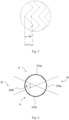
- the stent graft includes, in a circumferential direction, a region A and a region B connected with the region A, where a region surrounded by dotted lines in Fig. 1 is the region B.
- the wavy ring 101 includes first wavy segments located in the region A and second wavy segments located in the region B, wherein a wave included angle ⁇ of each first wavy segment is 70°-120°; the ratio of a wave height L1 of the first wavy segment to a spacing L2 between the adjacent first wavy segments is 1/4-3; a wave included angle ⁇ of the second wavy segment is 30°-60°; the ratio of a wave height L3 of the second wavy segment to a spacing L4 between the adjacent second wavy segments is 1/4-3/2; and the ratio of the wave height L1 of the first wavy segment to the wave height L3 of the second wavy segment is greater than or equal to 1/3 and less than 1.
- the wave included angle ⁇ refers to an included angle
- a puncture component is used to puncture a small hole in the stent graft, and the small hole is dilated to a required size by the use of a balloon.
- the wave heights of the wavy rings 101 in Figs. 3a, 3b and 3c are the same, and the wave included angles are 60°, 90° and 130°, respectively.
- a balloon with a diameter of D1 (such as D1 being 3-18 mm) is used to expand a circle of the same size in the corresponding position of each wavy ring 101, wherein the corresponding position refers to a position where the distance of a connecting line between the circle center of the balloon and a proximal vertex of the wavy ring 101 in each of Figs. 3a, 3b and 3c in the axis direction of the stent graft is equal.
- the hatched lines in the figures indicate the shapes of windows expanded by the balloon, and it can be seen from the figures that when the wave included angle is 90° or 130°, the windows meeting the size requirements may be expanded, while the wavy ring 101 with the wave included angle being 60° may limit the fenestration size so that a fenestration edge follows the wavy ring 101.
- the region of the wavy ring 101 covered by a circle with a diameter of D2 is a region where the wavy ring 101 supports the fenestration edge, that is, the greater the corresponding angle ⁇ of an intersection of the wavy ring 101 and the circle with the diameter of D2 is, the higher the supporting effect that the wavy ring 101 provides for the fenestration edge is.
- the larger the wave included angle is, the smaller the corresponding angle ⁇ of the intersection of the wavy ring 101 and the circle with the diameter of D2 is, leading to a failure to provide sufficient support for the fenestration edge by the wavy ring 101.
- the wavy ring 101 does not limit the fenestration size, thereby being beneficial to the fenestration; however, if the wave included angle is too large, the fenestration edge is caused to be far away from the wavy ring 101, and the wavy ring 101 cannot provide enough support for the fenestration edge; and if the fenestration edge lacks the support from the wavy ring 101, the window may be further expanded under the action of radial force of a branch stent, finally leading to the separation of the branch stent from the stent graft.
- the wave included angle of the wavy ring 101 is too large, the number of waves distributed in the circumferential direction of the stent graft in the region is too small, which is not conducive to maintaining the tube cavity shape of the stent graft.
- the wave included angle of the wavy ring 101 in a certain region is small, although enough support may be provided for the fenestration edge, the fenestration size may be limited, resulting in that the fenestration size hardly meets the size of a branch vessel.
- the wavy ring 101 has certain rigidity and is not prone to deformation under the action of external force, and after a fenestration component is abutted against the wavy ring 101, the wavy ring 101 is easily broken or the wavy ring 101 is excessively displaced with respect to the covering membrane 200, so that the radial supporting effect of the stent graft is affected.
- the region A can meet the requirements of fenestration, and the region B can meet the requirement of axial supporting force, so that the stent graft is prevented from shortening into a tumor cavity.
- the requirements of fenestration can be well met at each position of the region A, the adaptability of the stent graft is improved, and meanwhile, the situation that the bending property of the stent graft at the position is affected due to dense distribution of local waves in the region A and the region B, or the situation that the stent graft is prone to deformation due to poor the supporting effect of the stent graft in the position caused by sparse distribution of local waves in the region A and the region B, is avoided.
- the first wavy segment includes a plurality of first proximal vertexes 102a, a plurality of first distal vertexes 103a, and first supporting bodies 104a connecting the adjacent first proximal vertexes 102a and first distal vertexes 103a.
- the second wavy segment includes at least one second proximal vertex 102b, at least one second distal vertex 103b, and a second supporting body 104b connecting the adjacent second proximal vertex 102b and second distal vertex 103b.
- the wave height L1 of the first wavy segment refers to the distance in the axial direction between the first proximal vertex 102a and the first distal vertex 103a
- the spacing L2 between the adjacent first wavy segments is the distance in the axial direction between the first proximal vertex 102a on the first wavy segment and the first proximal vertex 102a on the adjacent first wavy segment.
- the wave height L3 of the second wavy segment refers to the distance in the axial direction between the second proximal vertex 102b and the second distal vertex 103b
- the spacing L4 of the adjacent second wavy segments is the distance in the axial direction between the second proximal vertex 102b on the second wavy segment and the second proximal vertex 102b on the adjacent second wavy segment.
- the first distal vertex 103a and the second distal vertex 103b are located in the same plane perpendicular to the longitudinal central axis of the stent graft.
- L1 and L3 meet the conditions that L1 is greater than or equal to 3 mm and less than or equal to 15 mm and L3 is greater than or equal to 8 mm and less than or equal to 18 mm.
- L1 is greater than or equal to 6 mm and less than or equal to 12 mm
- L3 is greater than or equal to 12 mm and less than or equal to 14 mm.
- FIGs. 4a, 4b and 4c are sequentially schematic diagrams of the adjacent first wavy segments being opposite in phase, being identical in phase, and having a phase difference, in the case that the wave structures and wave spacings of the adjacent first wavy segments are identical when the adjacent first wavy segments have no overlap in the axial direction.
- the being opposite in phase means that the wave crests of the first wavy segment are opposite to the wave troughs of the adjacent first wavy segment
- the being identical in phase means that the wave crests of the first wavy segment are opposite to the wave crests of the adjacent first wavy segment
- the phase difference means that the wave crests of the first wavy segment are staggered with the wave crests and troughs of the adjacent first wavy segment.
- different phase conditions can be adapted by adjusting the wave height of the first wavy segment and the ratio of the wave height to the wave spacing.
- the value of L1/L2 is greater than or equal to 1/3 and less than or equal to 1, and L1 is greater than or equal to 4 mm and less than or equal to 12 mm;
- the value of L1/L2 is greater than or equal to 1/4 and less than or equal to 3/4, and L1 is greater than or equal to 4 mm and less than or equal to 14 mm; and when the
- the value of L1/L2 is greater than 1 and less than or equal to 3, and L1 is greater than or equal to 5 mm and less than or equal to 15 mm.
- the corresponding wave crest here refers to a wave crest of the adjacent first wavy segment, having the shortest connecting distance between which and the wave crest of the first wavy segment than other wave crests of the adjacent first wavy segment; and the corresponding wave trough here refers to a wave trough of the adjacent first wavy segment, having the shortest connecting distance between which and the wave trough of the first wavy segment than other wave troughs of the adjacent first wavy segment.
- the region A includes two sub-regions, namely a greater curvature side region 100a and a lesser curvature side region 100b, that are distributed in the circumferential direction.
- the wave included angle of the greater curvature side region 100a is 80°-100°, such as 90°
- the wave included angle of the lesser curvature side region 100b is 75°-95°, such as 80°.
- the ratio of the wave height of the first wavy segment in the greater curvature side region 100a to the wave height of the first wavy segment in the lesser curvature side region 100b is about 0.7-1
- the ratio of the wave spacing between the adjacent first wavy segments in the greater curvature side region 100a to the wave spacing between the adjacent first wavy segments in the lesser curvature side region 100b is 0.7-1
- the ratio of the area covered by the greater curvature side region 100a on the outer surface of the stent graft to the area covered by the lesser curvature side region 100b on the outer surface of the stent graft is 0.7-1.3.
- the ratio of the area covered by the greater curvature side region 100a on the outer surface of the stent graft is equal to the area covered by the lesser curvature side region 100b on the outer surface of the stent graft, the wave heights of the first wavy segments in the greater curvature side region 100a are equal, and the wave spacings between the adjacent first wavy segments in the greater curvature side region 100a are equal. Also, the wave heights of the first wavy segments in the lesser curvature side region 100b are equal, and the wave spacings between the adjacent first wavy segments in the lesser curvature side region 100b are equal.
- the greater curvature side region 100a and the lesser curvature side region 100b are disposed oppositely in the circumferential direction, and the region B is connected between the greater curvature side region 100a and the lesser curvature side region 100b.
- the region A may also include three or more circumferentially distributed sub-regions as desired, the sub-regions may be arranged in a spaced manner or continuously, and the wave shapes, the number of waves, the wave heights, and the wave angles of the wavy segments of each sub-region may be set as desired.
- the axial shortening rate of the region B is less than the axial shortening rate of the region A, and the axial shortening rate of the stent graft in the region B is 10%-40%.
- a method for calculating the shortening rate of the stent graft in the axial direction is as follows: taking the length of the stent graft, which is in a straight tube shape, in the axial direction in a natural state as r and the diameter of the stent graft as d1, sleeving an inner tube with the diameter of d2 (d2 is less than d1, for example, d2 is equal to 90%*d1) with the stent graft, applying pressure F (1N ⁇ F ⁇ 2N) in the axial direction to the stent graft till the stent graft cannot shorten anymore to obtain the total length s, and calculating the axial shortening rate of the stent graft in the region B according to the formula (r-s)/r ⁇ 100%.
- the value of (r-s) is an available maximum shortening value of the stent graft.
- the stent graft sleeves the inner tube for shortening, so that the phenomenon that the stent graft is folded when shortening can be effectively avoided, that is, the value of (r-s) of the present application is the available maximum shortening value when the stent graft is not folded.
- the stent graft When the stent graft is in a frustum shape, that is, the diameters of the two ends of the stent graft are different, the length of the stent graft in the axial direction in the natural state is r, the diameter of the large end is d1, the diameter of the small end is d3, the stent graft sleeves a conical inner tube or a frustum inner tube with the same taper as the stent graft, and the perpendicular distance between the stent graft and the conical inner tube or the frustum inner tube is 0.05d1.
- the position of the small end of the stent graft is fixed and unchanged, the pressure F (1N ⁇ F ⁇ 2N) in the axial direction is applied to the large end, and the total length of the stent graft when the stent graft cannot shorten anymore is s, and thus the shortening rate of the stent graft in the axial direction is (r-s)/r 100%.
- the value of (r-s) is an available maximum shortening value of the stent graft.
- the stent graft sleeves the inner tube for shortening, so that the phenomenon that the stent graft is folded when shortening can be effectively avoided, that is, the value of (r-s) of the present application is the available maximum shortening value when the stent graft is not folded.
- the stent graft When the stent graft itself is manufactured into a bent shape, as shown in Fig. 7 , the stent graft includes a first bent section 400a and a second bent section 400b, the first bent section 400a has a first profile line 401a on a greater curvature side of the first bent section 400a and a second profile line 402a on a lesser curvature side of the first bent section 400a, and the second bent section 400b has a third profile line 401b on a greater curvature side of the second bent section 400b and a fourth profile line 402b on a lesser curvature side of the second bent section 400b.
- One method is as follows: referring to Fig. 8 together, by taking the first bent section 400a as an example, partitioning the first bent section 400a with a plane 109 perpendicular to the axial direction of the stent graft; cutting a plurality of notches 403 in the covering membranes 200 close to the second profile line 402a, wherein the sizes of the notches 403 can ensure that the stent graft is straightened along the first profile line 401a (or cutting a plurality of notches 403 in the covering membranes 200 close to the second profile line 402a, wherein the sizes of the notches 403 can exactly ensure that the stent graft is straightened along the first profile line 401a ); after the first bent section 400a is straightened as shown in Fig.
- the other method is as follows: also by taking the first bent section 400a as an example, re-arranging the wavy rings 101 in the axial direction according to the wave spacing between the wavy rings 101 at the first profile line 401a, covering the wavy rings 101 with membranes (covering materials and a selected process are kept consistent with those of the original stent), as shown in Fig. 10 , and then calculating the shortening rate according to the above-mentioned method for calculating the shortening rate.
- one wavy ring 101 of the stent graft moves in the direction of pressure together with portions of the covering membranes 200 fixed to the wavy ring 101, the portions of the covering membranes 200 fixed to the wavy ring 101 move together with portions of the covering membranes 200 distributed at the periphery of the wavy ring 101, immediately the portions of the covering membranes 200 distributed at the periphery of the wavy ring 101 pull another wavy ring 101 nearby to move towards one side close to the wavy ring 101 till the wavy ring 101 cannot keep moving, and at this time a rigid axial supporting structure is formed on the stent graft, so that the stent graft is prevented from continuing to shorten anymore.
- the axial shortening rate of the stent graft in the region B is less than 10%, the shortening rate of the region B is too small, and no matter to which direction the stent graft is bent, the region B easily reaches the available maximum shortening value, and the region B cannot shorten anymore, thereby restricting the stent graft from continuing to be bent.
- the axial shortening rate of the stent graft in the region B is greater than 40%, the axial supporting effect of the stent graft is poor, and the stent graft may enter the tumor cavity when the distal end of the stent graft shortens towards the proximal end of the stent graft, thus threatening the life of a patient.
- the stent graft When the shortening rate of the stent graft in the region B is 10%-40%, the stent graft can be bent towards all directions to adapt to bent blood vessels, and sufficient axial supporting force can be provided for the stent graft to achieve the axial shortening prevention effect, thus maintaining the tube cavity shape of the stent graft.
- the stent graft may be continuously bent towards different directions to better adapt to a bent blood vessel.
- the axial shortening rate of the stent graft in the region B is 20%-30%.
- the circumferential angle covered by the region B on an outer surface of the stent graft is ⁇ ° which is greater than or equal to 15° and less than or equal to 90°.
- ⁇ ° is less than 15°
- the circumferential angle covered by the region B on the outer surface of stent graft is small, so that poor axial supporting effect of the entire stent graft may be caused, and the stent graft may easily swing and retract under the impact of a blood flow, finally causing the stent graft to retract into the tumor cavity, and endangering the life of the patient; and when ⁇ ° is greater than 90°, the circumferential angle covered by the region B on the outer surface of the stent graft is large, which is not conducive to stent bending.
- ⁇ ° is greater than or equal to 15° and less than or equal to 90°, sufficient axial support can be provided for the stent graft, and when the stent graft is applied to a more bent blood vessel, no folding occurs, thereby keeping the tube cavity smooth, and enabling the stent graft to adapt to a wider range of vascular morphology.
- the region B includes two keel regions in the circumferential direction, namely a first keel region 300a and a second keel region 300b, which are located between the greater curvature side region 100a and the lesser curvature side region 100b, respectively.
- Circumferential angles covered by the first keel region 300a and the second keel region 300b on the outer surface of the stent graft are 15°-45°, such as about 20°-30°, and the circumferential angles covered by the first keel region 300a and the second keel region 300b may be identical or different.
- the region B may also include three or more keel regions as desired, the keel regions may be arranged in a spaced manner or continuously, and the wave shapes, the number of waves, the wave heights, and the wave angles of the wavy segments of each keel region may be set as desired.
- the second wavy segment includes a second proximal vertex 102b, and the connecting line between the second proximal vertexes 102b of the adjacent second wavy segments is parallel to the axis of the stent graft.
- At least one proximal wavy ring 101a is disposed at one end of the plurality of wavy rings 101.
- the wave included angle of the proximal wavy ring 101a is 30°-60°
- the waves of the proximal wavy ring 101a and the wavy rings 101 are the same, and both are V-shaped, Z-shaped, M-shaped, or the like
- the number of the waves of the proximal wavy ring 101a in the circumferential direction is greater than the number of the waves of the wavy ring 101 in the circumferential direction.
- the proximal wavy rings 101a located at an end portion of the stent graft has a greater number of waves in the circumferential direction, the radial supporting force of the end portion of the stent graft is high, and the wall adhering effect of the end portion of the stent graft may be effectively improved.
- At least one distal wavy ring (not shown) is also disposed at the other end of the plurality of wavy rings 101, the wave included angle of the distal wavy ring is 50°-70°, the waves of the distal wavy ring and the wavy rings 101 are the same, and both are V-shaped, Z-shaped, M-shaped, or the like, and the number of the waves of the distal wavy ring in the circumferential direction is greater than the number of the waves of the wavy ring 101 in the circumferential direction.
- both the proximal wavy ring and the distal wavy ring are made of materials having good biocompatibility, such as nickel titanium, stainless steel or the like.
- the proximal wavy ring and the distal wavy ring are both of closed cylindrical structures.
- the proximal wavy ring and the distal wavy ring may be of Z-shaped wave, M-shaped wave, V-shaped wave or sinusoidal wave structures, or of other structures that are radially compressible to a very small diameter. It will be appreciated that not only the numbers of the proximal wavy ring and the distal wavy ring may be set as desired, but also the wave shapes, the number of waves, and the wave heights of the proximal wavy ring and the distal wavy ring may be set as desired.
- the stent graft further includes an anchoring bare stent 105 located at one or two ends of the stent graft and connected with the proximal wavy ring or the distal wavy ring.
- Fig. 12 shows a stent graft provided by a second exemplary embodiment of the present application, which differs from the first embodiment in that a connecting line between the second proximal vertexes 102b of the adjacent second wavy segments is disposed obliquely with respect to the axis of stent graft.
- Fig. 13 shows a stent graft provided by a third exemplary embodiment of the present application, which differs from the first embodiment in that the second supporting bodies 104b that are connected to one sides of the second proximal vertexes 102b and close to the greater curvature side region 100a are distributed in the direction parallel to the axial direction of the stent graft, and the second supporting bodies 104b that are connected to the other sides of the second proximal vertexes 102b and close to the lesser curvature side region 100b are disposed obliquely with respect to the axis direction of the stent graft.
- the second supporting bodies 104b, adjacent to the lesser curvature side region 100b, of the adjacent second wavy segments abut against mutually to form axial support
- the included angle between the second supporting bodies 104b, adjacent to the lesser curvature side region 100b, of the adjacent second wavy segments is ⁇ °.
- ⁇ ° is less than ⁇ °.
- the axial supporting effect formed when the second supporting bodies 104b distributed in the direction parallel to the axial direction of the stent graft abut against mutually in Fig. 14 is superior to the axial supporting effect formed when the second supporting bodies 104b disposed obliquely with respect to the axis direction of the stent graft abut against mutually in Fig. 15 .
- the included angle between the second supporting bodies 104b of the adjacent second wavy segments is greater, excessive deformation of the covering membranes of the keel regions is easily caused to bring about an uneven surface of the stent graft, thus leading to high probability of thrombosis.
- the second supporting bodies 104b distributed in the direction parallel to the axial direction of the stent graft abut against mutually to form the axial support, the greater the included angle between the second supporting bodies 104b of the adjacent second wavy segments is, the higher the axial supporting force of the stent graft is. Therefore, the second supporting bodies 104b distributed in the direction parallel to the axial direction of the stent graft are disposed on one side close to the greater curvature side region 100a, and when the stent graft is bent towards the lesser curvature side, the second supporting bodies 104b may provide enough axial supporting force for the stent graft, and the axial supporting effect on the stent graft is optimal.
Landscapes
- Health & Medical Sciences (AREA)
- Engineering & Computer Science (AREA)
- Biomedical Technology (AREA)
- Life Sciences & Earth Sciences (AREA)
- Veterinary Medicine (AREA)
- Public Health (AREA)
- General Health & Medical Sciences (AREA)
- Animal Behavior & Ethology (AREA)
- Heart & Thoracic Surgery (AREA)
- Cardiology (AREA)
- Vascular Medicine (AREA)
- Transplantation (AREA)
- Oral & Maxillofacial Surgery (AREA)
- Pulmonology (AREA)
- Gastroenterology & Hepatology (AREA)
- Hematology (AREA)
- Anesthesiology (AREA)
- Optics & Photonics (AREA)
- Physics & Mathematics (AREA)
- Chemical & Material Sciences (AREA)
- Bioinformatics & Cheminformatics (AREA)
- Medicinal Chemistry (AREA)
- Prostheses (AREA)
Claims (10)
- Stenttransplantat, das eine Vielzahl von gewellten Ringen (101) umfasst, wobei das Stenttransplantat ferner entlang einer Umfangsrichtung einen Bereich A und einen mit dem Bereich A verbundenen Bereich B umfasst, wobei jeder gewellte Ring (101) erste gewellte Segmente, die sich in dem Bereich A befinden, und zweite gewellte Segmente, die sich in dem Bereich B befinden, umfasst, wobei der Bereich A zur Fensterung dient; das Verhältnis einer Wellenhöhe (L1) des ersten wellenförmigen Segments zu einem Abstand (L2) zwischen den benachbarten ersten wellenförmigen Segmenten im Bereich von 1/4 bis 3 liegt; ein von einer Welle enthaltener Winkel (α) jedes zweiten wellenförmigen Segments im Bereich von 30° bis 60° liegt; das Verhältnis einer Wellenhöhe (L3) des zweiten wellenförmigen Segments zu einem Abstand (L4) zwischen den benachbarten zweiten wellenförmigen Segmenten im Bereich von 1/4 bis 3/2 liegt; und das Verhältnis der Wellenhöhe (L1) des ersten wellenförmigen Segments zur Wellenhöhe (L3) des zweiten wellenförmigen Segments größer als oder gleich 1/3 und kleiner als 1 ist, dadurch gekennzeichnet, dass ein von einer Welle enthaltener Winkel (α) jedes ersten wellenförmigen Segments im Bereich von 70° bis 120° liegt.
- Stentgraft nach Anspruch 1, wobei der Bereich A einen Bereich (100a) auf der Seite größerer Krümmung und einen Bereich (100b) auf der Seite geringerer Krümmung umfasst, die entlang der Umfangsrichtung verteilt sind, der Winkel (α), den die Welle enthält, des Bereichs (100a) auf der Seite der größeren Krümmung im Bereich von 80° bis 100° liegt und der Winkel (α), den die Welle enthält, des Bereichs (100b) auf der Seite der geringeren Krümmung im Bereich von 75° bis 95° liegt.
- Stentgraft nach Anspruch 2, wobei das Verhältnis der Wellenhöhe (L1) des ersten gewellten Segments im Bereich der Seite mit größerer Krümmung (100a) zur Wellenhöhe (L1) des ersten gewellten Segments im Bereich der Seite mit geringerer Krümmung (100b) im Bereich von 0,7 bis 1 liegt.
- Stentgraft nach Anspruch 2, wobei das Verhältnis des Wellenabstands der benachbarten ersten gewellten Segmente im Bereich der Seite mit größerer Krümmung (100a) zum Wellenabstand zwischen den benachbarten ersten gewellten Segmenten im Bereich der Seite mit geringerer Krümmung (100b) im Bereich von 0,7 bis 1, liegt.
- Stentgraft nach Anspruch 2, wobei das Verhältnis der Fläche, die von dem Bereich (100a) auf der Seite der größeren Krümmung auf einer Außenfläche des Stenttransplantats bedeckt wird, zu der Fläche, die von dem Bereich (100b) auf der Seite der geringeren Krümmung auf der Außenfläche des Stenttransplantats bedeckt wird, im Bereich von 0,7 bis 1,3 liegt.
- Stentgraft nach Anspruch 2, wobei der Bereich (100a) auf der Seite der größeren Krümmung und der Bereich (100b) auf der Seite der geringeren Krümmung symmetrisch in Umfangsrichtung angeordnet sind und der Bereich B zwischen dem Bereich (100a) auf der Seite der größeren Krümmung und dem Bereich (100b) auf der Seite der geringeren Krümmung angeordnet ist.
- Stentgraft nach Anspruch 1, wobei der eingeschlossene Winkel des Bereichs B in der Umfangsrichtung von 15° bis 90° reicht.
- Stentgraft nach Anspruch 1, wobei, wenn eine Verbindungslinie zwischen einem Wellenberg des ersten wellenförmigen Segments und einem entsprechenden Wellenberg des benachbarten ersten wellenförmigen Segments parallel zu einer Sammelschiene des Stenttransplantats ist, der Wert von L1/L2 größer oder gleich 1/3 und kleiner oder gleich 1 ist und L1 größer oder gleich 4 mm und kleiner oder gleich 12 mm ist.
- Stentgraft nach Anspruch 8, wobei, wenn eine Verbindungslinie zwischen dem Wellenberg des ersten wellenförmigen Segments und einem entsprechenden Wellental des benachbarten ersten wellenförmigen Segments parallel zu der Sammelschiene des Stenttransplantats ist, der Wert von L1/L2 größer oder gleich 1/4 und kleiner oder gleich 3/4 ist und L1 größer oder gleich 4 mm und kleiner oder gleich 14 mm ist.
- Stentgraft nach Anspruch 1, wobei die Wellenhöhe (L1) des ersten gewellten Segments im Bereich von 3 bis 15 mm liegt und die Wellenhöhe (L3) des zweiten gewellten Segments im Bereich von 8 bis 18 mm liegt.
Applications Claiming Priority (2)
| Application Number | Priority Date | Filing Date | Title |
|---|---|---|---|
| CN201711446248.0A CN109966034B (zh) | 2017-12-27 | 2017-12-27 | 覆膜支架 |
| PCT/CN2018/120319 WO2019128701A1 (zh) | 2017-12-27 | 2018-12-11 | 覆膜支架 |
Publications (3)
| Publication Number | Publication Date |
|---|---|
| EP3733126A1 EP3733126A1 (de) | 2020-11-04 |
| EP3733126A4 EP3733126A4 (de) | 2021-02-24 |
| EP3733126B1 true EP3733126B1 (de) | 2024-11-27 |
Family
ID=67066556
Family Applications (1)
| Application Number | Title | Priority Date | Filing Date |
|---|---|---|---|
| EP18897536.1A Active EP3733126B1 (de) | 2017-12-27 | 2018-12-11 | Stentimplantat |
Country Status (5)
| Country | Link |
|---|---|
| US (1) | US11576768B2 (de) |
| EP (1) | EP3733126B1 (de) |
| CN (1) | CN109966034B (de) |
| ES (1) | ES2998085T3 (de) |
| WO (1) | WO2019128701A1 (de) |
Families Citing this family (7)
| Publication number | Priority date | Publication date | Assignee | Title |
|---|---|---|---|---|
| CN109966034B (zh) | 2017-12-27 | 2021-08-17 | 先健科技(深圳)有限公司 | 覆膜支架 |
| CN112971872B (zh) * | 2019-12-17 | 2022-12-20 | 先健科技(深圳)有限公司 | 推送缆及推送系统 |
| CN113081386B (zh) * | 2019-12-23 | 2023-09-19 | 先健科技(深圳)有限公司 | 覆膜支架 |
| CN113397774A (zh) * | 2020-02-29 | 2021-09-17 | 上海市同仁医院 | 分段双膜柔支架及其制造方法 |
| WO2022009924A1 (ja) * | 2020-07-07 | 2022-01-13 | 国立大学法人広島大学 | ステントグラフト |
| CN114099062B (zh) * | 2020-08-27 | 2026-01-02 | 先健科技(深圳)有限公司 | 覆膜支架 |
| CN116407335A (zh) * | 2021-12-31 | 2023-07-11 | 先健科技(深圳)有限公司 | 覆膜支架及覆膜支架输送系统 |
Family Cites Families (35)
| Publication number | Priority date | Publication date | Assignee | Title |
|---|---|---|---|---|
| US6375676B1 (en) * | 1999-05-17 | 2002-04-23 | Advanced Cardiovascular Systems, Inc. | Self-expanding stent with enhanced delivery precision and stent delivery system |
| US6569193B1 (en) * | 1999-07-22 | 2003-05-27 | Advanced Cardiovascular Systems, Inc. | Tapered self-expanding stent |
| US6423090B1 (en) * | 2000-02-11 | 2002-07-23 | Advanced Cardiovascular Systems, Inc. | Stent pattern with staged expansion |
| US7331986B2 (en) * | 2002-10-09 | 2008-02-19 | Boston Scientific Scimed, Inc. | Intraluminal medical device having improved visibility |
| US7223283B2 (en) * | 2002-10-09 | 2007-05-29 | Boston Scientific Scimed, Inc. | Stent with improved flexibility |
| US7625401B2 (en) * | 2003-05-06 | 2009-12-01 | Abbott Laboratories | Endoprosthesis having foot extensions |
| US6846323B2 (en) | 2003-05-15 | 2005-01-25 | Advanced Cardiovascular Systems, Inc. | Intravascular stent |
| US7763063B2 (en) * | 2003-09-03 | 2010-07-27 | Bolton Medical, Inc. | Self-aligning stent graft delivery system, kit, and method |
| US20050278017A1 (en) * | 2004-06-09 | 2005-12-15 | Scimed Life Systems, Inc. | Overlapped stents for scaffolding, flexibility and MRI compatibility |
| US7837726B2 (en) * | 2005-03-14 | 2010-11-23 | Abbott Laboratories | Visible endoprosthesis |
| CN2822554Y (zh) * | 2005-07-27 | 2006-10-04 | 深圳市先健科技股份有限公司 | 避免移位的无缝合线的血管覆膜支架 |
| US8663307B2 (en) * | 2005-09-02 | 2014-03-04 | Medtronic Vascular, Inc. | Endoluminal prosthesis |
| JP4835113B2 (ja) * | 2005-11-07 | 2011-12-14 | 株式会社カネカ | ステント |
| WO2007088549A2 (en) | 2006-02-03 | 2007-08-09 | Design & Performance - Cyprus Limited | Implantable graft assembly and aneurysm treatment |
| WO2008005111A1 (en) * | 2006-06-30 | 2008-01-10 | Boston Scientific Limited | Stent design with variable expansion columns along circumference |
| US7615072B2 (en) * | 2006-11-14 | 2009-11-10 | Medtronic Vascular, Inc. | Endoluminal prosthesis |
| US8734502B2 (en) * | 2008-12-17 | 2014-05-27 | Cook Medical Technologies Llc | Tapered stent and flexible prosthesis |
| US8641753B2 (en) * | 2009-01-31 | 2014-02-04 | Cook Medical Technologies Llc | Preform for and an endoluminal prosthesis |
| CN201438978U (zh) | 2009-07-03 | 2010-04-21 | 先健科技(深圳)有限公司 | 血管覆膜支架 |
| EP2680797B1 (de) * | 2011-03-03 | 2016-10-26 | Boston Scientific Scimed, Inc. | Hochfester stent mit niedriger deformation |
| DE112012005518T5 (de) * | 2011-12-29 | 2014-09-18 | Beijing Percutek Therapeutics Co. Ltd. | Ein Aorten-Stent-Graft |
| DE102012111225A1 (de) * | 2012-11-21 | 2014-05-22 | Jotec Gmbh | Gefäßimplantat mit Seitenast |
| US9439751B2 (en) * | 2013-03-15 | 2016-09-13 | Bolton Medical, Inc. | Hemostasis valve and delivery systems |
| US9498360B2 (en) * | 2013-03-15 | 2016-11-22 | Stryker Corporation | Stent and method of use |
| US9486306B2 (en) | 2013-04-02 | 2016-11-08 | Tendyne Holdings, Inc. | Inflatable annular sealing device for prosthetic mitral valve |
| CN104586536B (zh) | 2013-10-31 | 2017-05-03 | 微创心脉医疗科技(上海)有限公司 | 一种覆膜支架 |
| CN103598929B (zh) | 2013-11-28 | 2016-04-20 | 先健科技(深圳)有限公司 | 胸主动脉覆膜支架 |
| CN104116577B (zh) * | 2014-06-27 | 2017-07-14 | 先健科技(深圳)有限公司 | 分叉型覆膜支架 |
| CN104905892B (zh) * | 2015-06-16 | 2017-06-13 | 中国人民解放军第四军医大学 | 一体化多分支型介入主动脉弓覆膜支架 |
| CN205019198U (zh) * | 2015-09-07 | 2016-02-10 | 黄连军 | 主动脉覆膜支架 |
| CN109077836B (zh) * | 2015-12-30 | 2021-01-22 | 先健科技(深圳)有限公司 | 管腔支架 |
| CN105496603B (zh) * | 2015-12-30 | 2018-11-06 | 先健科技(深圳)有限公司 | 管腔支架 |
| CN107242917B (zh) * | 2017-07-05 | 2023-09-19 | 上海长海医院 | 一种支架移植物 |
| CN209474879U (zh) * | 2017-11-24 | 2019-10-11 | 杭州唯强医疗科技有限公司 | 改进贴壁性的血管分流架及血管支架 |
| CN109966034B (zh) | 2017-12-27 | 2021-08-17 | 先健科技(深圳)有限公司 | 覆膜支架 |
-
2017
- 2017-12-27 CN CN201711446248.0A patent/CN109966034B/zh active Active
-
2018
- 2018-12-11 US US16/956,070 patent/US11576768B2/en active Active
- 2018-12-11 EP EP18897536.1A patent/EP3733126B1/de active Active
- 2018-12-11 WO PCT/CN2018/120319 patent/WO2019128701A1/zh not_active Ceased
- 2018-12-11 ES ES18897536T patent/ES2998085T3/es active Active
Also Published As
| Publication number | Publication date |
|---|---|
| US11576768B2 (en) | 2023-02-14 |
| CN109966034A (zh) | 2019-07-05 |
| CN109966034B (zh) | 2021-08-17 |
| EP3733126A1 (de) | 2020-11-04 |
| EP3733126A4 (de) | 2021-02-24 |
| US20210093439A1 (en) | 2021-04-01 |
| ES2998085T3 (en) | 2025-02-19 |
| WO2019128701A1 (zh) | 2019-07-04 |
Similar Documents
| Publication | Publication Date | Title |
|---|---|---|
| EP3733126B1 (de) | Stentimplantat | |
| US12324735B2 (en) | Stent graft with variable coverage of wavy rings | |
| KR100316863B1 (ko) | 판형재료로형성된패턴을가진가요성스텐트 | |
| US6270524B1 (en) | Flexible, radially expansible luminal prostheses | |
| US8382820B2 (en) | Stent having helical elements | |
| US20030176914A1 (en) | Multi-segment modular stent and methods for manufacturing stents | |
| US20100004728A1 (en) | Graft endoframe having axially variable characteristics | |
| US20060184232A1 (en) | Methods and apparatus for curved stent | |
| US20140088689A1 (en) | Tapered Helical Stent and Method for Manufacturing the Stent | |
| US12097110B2 (en) | Covered stent | |
| JPH11221288A (ja) | 多重ブリッジ形接合部を有する内視鏡手術用プロテーゼとその操作法 | |
| CN110916742B (zh) | 具有纵向可变宽度支柱的支架 | |
| US11033377B2 (en) | Stent | |
| US12070400B2 (en) | Endoluminal prosthesis systems and methods | |
| CN109966017B (zh) | 覆膜支架 | |
| WO2002064061A2 (en) | Stent having a web structure and suitable for forming a curved stent | |
| KR20020012533A (ko) | 팽창가능한 스텐트와 이를 제조하는 방법 | |
| US20180360627A1 (en) | Stent with helical groove |
Legal Events
| Date | Code | Title | Description |
|---|---|---|---|
| STAA | Information on the status of an ep patent application or granted ep patent |
Free format text: STATUS: THE INTERNATIONAL PUBLICATION HAS BEEN MADE |
|
| PUAI | Public reference made under article 153(3) epc to a published international application that has entered the european phase |
Free format text: ORIGINAL CODE: 0009012 |
|
| STAA | Information on the status of an ep patent application or granted ep patent |
Free format text: STATUS: REQUEST FOR EXAMINATION WAS MADE |
|
| 17P | Request for examination filed |
Effective date: 20200706 |
|
| AK | Designated contracting states |
Kind code of ref document: A1 Designated state(s): AL AT BE BG CH CY CZ DE DK EE ES FI FR GB GR HR HU IE IS IT LI LT LU LV MC MK MT NL NO PL PT RO RS SE SI SK SM TR |
|
| AX | Request for extension of the european patent |
Extension state: BA ME |
|
| A4 | Supplementary search report drawn up and despatched |
Effective date: 20210121 |
|
| RIC1 | Information provided on ipc code assigned before grant |
Ipc: A61F 2/07 20130101AFI20210115BHEP Ipc: A61F 2/89 20130101ALI20210115BHEP |
|
| DAV | Request for validation of the european patent (deleted) | ||
| DAX | Request for extension of the european patent (deleted) | ||
| GRAP | Despatch of communication of intention to grant a patent |
Free format text: ORIGINAL CODE: EPIDOSNIGR1 |
|
| STAA | Information on the status of an ep patent application or granted ep patent |
Free format text: STATUS: GRANT OF PATENT IS INTENDED |
|
| RIC1 | Information provided on ipc code assigned before grant |
Ipc: A61F 2/915 20130101ALI20240513BHEP Ipc: A61M 31/00 20060101ALI20240513BHEP Ipc: A61F 2/91 20130101ALI20240513BHEP Ipc: A61F 2/89 20130101ALI20240513BHEP Ipc: A61F 2/07 20130101AFI20240513BHEP |
|
| INTG | Intention to grant announced |
Effective date: 20240617 |
|
| GRAS | Grant fee paid |
Free format text: ORIGINAL CODE: EPIDOSNIGR3 |
|
| GRAA | (expected) grant |
Free format text: ORIGINAL CODE: 0009210 |
|
| STAA | Information on the status of an ep patent application or granted ep patent |
Free format text: STATUS: THE PATENT HAS BEEN GRANTED |
|
| RAP3 | Party data changed (applicant data changed or rights of an application transferred) |
Owner name: LIFETECH SCIENTIFIC (SHENZHEN) CO., LTD |
|
| P01 | Opt-out of the competence of the unified patent court (upc) registered |
Free format text: CASE NUMBER: APP_55905/2024 Effective date: 20241011 |
|
| AK | Designated contracting states |
Kind code of ref document: B1 Designated state(s): AL AT BE BG CH CY CZ DE DK EE ES FI FR GB GR HR HU IE IS IT LI LT LU LV MC MK MT NL NO PL PT RO RS SE SI SK SM TR |
|
| REG | Reference to a national code |
Ref country code: GB Ref legal event code: FG4D |
|
| REG | Reference to a national code |
Ref country code: CH Ref legal event code: EP |
|
| REG | Reference to a national code |
Ref country code: IE Ref legal event code: FG4D |
|
| REG | Reference to a national code |
Ref country code: DE Ref legal event code: R096 Ref document number: 602018077113 Country of ref document: DE |
|
| REG | Reference to a national code |
Ref country code: ES Ref legal event code: FG2A Ref document number: 2998085 Country of ref document: ES Kind code of ref document: T3 Effective date: 20250219 |
|
| REG | Reference to a national code |
Ref country code: LT Ref legal event code: MG9D |
|
| REG | Reference to a national code |
Ref country code: NL Ref legal event code: MP Effective date: 20241127 |
|
| PG25 | Lapsed in a contracting state [announced via postgrant information from national office to epo] |
Ref country code: PT Free format text: LAPSE BECAUSE OF FAILURE TO SUBMIT A TRANSLATION OF THE DESCRIPTION OR TO PAY THE FEE WITHIN THE PRESCRIBED TIME-LIMIT Effective date: 20250327 Ref country code: IS Free format text: LAPSE BECAUSE OF FAILURE TO SUBMIT A TRANSLATION OF THE DESCRIPTION OR TO PAY THE FEE WITHIN THE PRESCRIBED TIME-LIMIT Effective date: 20250327 Ref country code: HR Free format text: LAPSE BECAUSE OF FAILURE TO SUBMIT A TRANSLATION OF THE DESCRIPTION OR TO PAY THE FEE WITHIN THE PRESCRIBED TIME-LIMIT Effective date: 20241127 |
|
| PG25 | Lapsed in a contracting state [announced via postgrant information from national office to epo] |
Ref country code: FI Free format text: LAPSE BECAUSE OF FAILURE TO SUBMIT A TRANSLATION OF THE DESCRIPTION OR TO PAY THE FEE WITHIN THE PRESCRIBED TIME-LIMIT Effective date: 20241127 Ref country code: NL Free format text: LAPSE BECAUSE OF FAILURE TO SUBMIT A TRANSLATION OF THE DESCRIPTION OR TO PAY THE FEE WITHIN THE PRESCRIBED TIME-LIMIT Effective date: 20241127 |
|
| REG | Reference to a national code |
Ref country code: AT Ref legal event code: MK05 Ref document number: 1744994 Country of ref document: AT Kind code of ref document: T Effective date: 20241127 |
|
| PG25 | Lapsed in a contracting state [announced via postgrant information from national office to epo] |
Ref country code: BG Free format text: LAPSE BECAUSE OF FAILURE TO SUBMIT A TRANSLATION OF THE DESCRIPTION OR TO PAY THE FEE WITHIN THE PRESCRIBED TIME-LIMIT Effective date: 20241127 |
|
| PG25 | Lapsed in a contracting state [announced via postgrant information from national office to epo] |
Ref country code: NO Free format text: LAPSE BECAUSE OF FAILURE TO SUBMIT A TRANSLATION OF THE DESCRIPTION OR TO PAY THE FEE WITHIN THE PRESCRIBED TIME-LIMIT Effective date: 20250227 |
|
| PG25 | Lapsed in a contracting state [announced via postgrant information from national office to epo] |
Ref country code: LV Free format text: LAPSE BECAUSE OF FAILURE TO SUBMIT A TRANSLATION OF THE DESCRIPTION OR TO PAY THE FEE WITHIN THE PRESCRIBED TIME-LIMIT Effective date: 20241127 Ref country code: GR Free format text: LAPSE BECAUSE OF FAILURE TO SUBMIT A TRANSLATION OF THE DESCRIPTION OR TO PAY THE FEE WITHIN THE PRESCRIBED TIME-LIMIT Effective date: 20250228 Ref country code: AT Free format text: LAPSE BECAUSE OF FAILURE TO SUBMIT A TRANSLATION OF THE DESCRIPTION OR TO PAY THE FEE WITHIN THE PRESCRIBED TIME-LIMIT Effective date: 20241127 |
|
| PG25 | Lapsed in a contracting state [announced via postgrant information from national office to epo] |
Ref country code: PL Free format text: LAPSE BECAUSE OF FAILURE TO SUBMIT A TRANSLATION OF THE DESCRIPTION OR TO PAY THE FEE WITHIN THE PRESCRIBED TIME-LIMIT Effective date: 20241127 |
|
| PG25 | Lapsed in a contracting state [announced via postgrant information from national office to epo] |
Ref country code: RS Free format text: LAPSE BECAUSE OF FAILURE TO SUBMIT A TRANSLATION OF THE DESCRIPTION OR TO PAY THE FEE WITHIN THE PRESCRIBED TIME-LIMIT Effective date: 20250227 |
|
| PG25 | Lapsed in a contracting state [announced via postgrant information from national office to epo] |
Ref country code: SM Free format text: LAPSE BECAUSE OF FAILURE TO SUBMIT A TRANSLATION OF THE DESCRIPTION OR TO PAY THE FEE WITHIN THE PRESCRIBED TIME-LIMIT Effective date: 20241127 |
|
| PG25 | Lapsed in a contracting state [announced via postgrant information from national office to epo] |
Ref country code: DK Free format text: LAPSE BECAUSE OF FAILURE TO SUBMIT A TRANSLATION OF THE DESCRIPTION OR TO PAY THE FEE WITHIN THE PRESCRIBED TIME-LIMIT Effective date: 20241127 |
|
| PG25 | Lapsed in a contracting state [announced via postgrant information from national office to epo] |
Ref country code: EE Free format text: LAPSE BECAUSE OF FAILURE TO SUBMIT A TRANSLATION OF THE DESCRIPTION OR TO PAY THE FEE WITHIN THE PRESCRIBED TIME-LIMIT Effective date: 20241127 |
|
| PG25 | Lapsed in a contracting state [announced via postgrant information from national office to epo] |
Ref country code: RO Free format text: LAPSE BECAUSE OF FAILURE TO SUBMIT A TRANSLATION OF THE DESCRIPTION OR TO PAY THE FEE WITHIN THE PRESCRIBED TIME-LIMIT Effective date: 20241127 |
|
| PG25 | Lapsed in a contracting state [announced via postgrant information from national office to epo] |
Ref country code: SK Free format text: LAPSE BECAUSE OF FAILURE TO SUBMIT A TRANSLATION OF THE DESCRIPTION OR TO PAY THE FEE WITHIN THE PRESCRIBED TIME-LIMIT Effective date: 20241127 |
|
| PG25 | Lapsed in a contracting state [announced via postgrant information from national office to epo] |
Ref country code: CZ Free format text: LAPSE BECAUSE OF FAILURE TO SUBMIT A TRANSLATION OF THE DESCRIPTION OR TO PAY THE FEE WITHIN THE PRESCRIBED TIME-LIMIT Effective date: 20241127 |
|
| REG | Reference to a national code |
Ref country code: CH Ref legal event code: PL |
|
| PG25 | Lapsed in a contracting state [announced via postgrant information from national office to epo] |
Ref country code: LU Free format text: LAPSE BECAUSE OF NON-PAYMENT OF DUE FEES Effective date: 20241211 |
|
| REG | Reference to a national code |
Ref country code: DE Ref legal event code: R097 Ref document number: 602018077113 Country of ref document: DE |
|
| PG25 | Lapsed in a contracting state [announced via postgrant information from national office to epo] |
Ref country code: SE Free format text: LAPSE BECAUSE OF FAILURE TO SUBMIT A TRANSLATION OF THE DESCRIPTION OR TO PAY THE FEE WITHIN THE PRESCRIBED TIME-LIMIT Effective date: 20241127 |
|
| PG25 | Lapsed in a contracting state [announced via postgrant information from national office to epo] |
Ref country code: MC Free format text: LAPSE BECAUSE OF FAILURE TO SUBMIT A TRANSLATION OF THE DESCRIPTION OR TO PAY THE FEE WITHIN THE PRESCRIBED TIME-LIMIT Effective date: 20241127 |
|
| PLBE | No opposition filed within time limit |
Free format text: ORIGINAL CODE: 0009261 |
|
| STAA | Information on the status of an ep patent application or granted ep patent |
Free format text: STATUS: NO OPPOSITION FILED WITHIN TIME LIMIT |
|
| REG | Reference to a national code |
Ref country code: BE Ref legal event code: MM Effective date: 20241231 |
|
| PG25 | Lapsed in a contracting state [announced via postgrant information from national office to epo] |
Ref country code: BE Free format text: LAPSE BECAUSE OF NON-PAYMENT OF DUE FEES Effective date: 20241231 |
|
| PG25 | Lapsed in a contracting state [announced via postgrant information from national office to epo] |
Ref country code: FR Free format text: LAPSE BECAUSE OF NON-PAYMENT OF DUE FEES Effective date: 20250127 |
|
| PG25 | Lapsed in a contracting state [announced via postgrant information from national office to epo] |
Ref country code: CH Free format text: LAPSE BECAUSE OF NON-PAYMENT OF DUE FEES Effective date: 20241231 |
|
| PG25 | Lapsed in a contracting state [announced via postgrant information from national office to epo] |
Ref country code: IE Free format text: LAPSE BECAUSE OF NON-PAYMENT OF DUE FEES Effective date: 20241211 |
|
| GBPC | Gb: european patent ceased through non-payment of renewal fee |
Effective date: 20250227 |
|
| 26N | No opposition filed |
Effective date: 20250828 |
|
| PG25 | Lapsed in a contracting state [announced via postgrant information from national office to epo] |
Ref country code: GB Free format text: LAPSE BECAUSE OF NON-PAYMENT OF DUE FEES Effective date: 20250227 |
|
| PGFP | Annual fee paid to national office [announced via postgrant information from national office to epo] |
Ref country code: IT Payment date: 20251210 Year of fee payment: 8 |
|
| PGFP | Annual fee paid to national office [announced via postgrant information from national office to epo] |
Ref country code: ES Payment date: 20260112 Year of fee payment: 8 |
|
| PGFP | Annual fee paid to national office [announced via postgrant information from national office to epo] |
Ref country code: DE Payment date: 20251231 Year of fee payment: 8 |