EP3733127B1 - Stent luminal - Google Patents
Stent luminal Download PDFInfo
- Publication number
- EP3733127B1 EP3733127B1 EP18897682.3A EP18897682A EP3733127B1 EP 3733127 B1 EP3733127 B1 EP 3733127B1 EP 18897682 A EP18897682 A EP 18897682A EP 3733127 B1 EP3733127 B1 EP 3733127B1
- Authority
- EP
- European Patent Office
- Prior art keywords
- skirt
- support structure
- radial support
- tubular body
- proximal
- Prior art date
- Legal status (The legal status is an assumption and is not a legal conclusion. Google has not performed a legal analysis and makes no representation as to the accuracy of the status listed.)
- Active
Links
Images



Classifications
-
- A—HUMAN NECESSITIES
- A61—MEDICAL OR VETERINARY SCIENCE; HYGIENE
- A61F—FILTERS IMPLANTABLE INTO BLOOD VESSELS; PROSTHESES; DEVICES PROVIDING PATENCY TO, OR PREVENTING COLLAPSING OF, TUBULAR STRUCTURES OF THE BODY, e.g. STENTS; ORTHOPAEDIC, NURSING OR CONTRACEPTIVE DEVICES; FOMENTATION; TREATMENT OR PROTECTION OF EYES OR EARS; BANDAGES, DRESSINGS OR ABSORBENT PADS; FIRST-AID KITS
- A61F2/00—Filters implantable into blood vessels; Prostheses, i.e. artificial substitutes or replacements for parts of the body; Appliances for connecting them with the body; Devices providing patency to, or preventing collapsing of, tubular structures of the body, e.g. stents
- A61F2/02—Prostheses implantable into the body
- A61F2/04—Hollow or tubular parts of organs, e.g. bladders, tracheae, bronchi or bile ducts
- A61F2/06—Blood vessels
- A61F2/07—Stent-grafts
-
- A—HUMAN NECESSITIES
- A61—MEDICAL OR VETERINARY SCIENCE; HYGIENE
- A61F—FILTERS IMPLANTABLE INTO BLOOD VESSELS; PROSTHESES; DEVICES PROVIDING PATENCY TO, OR PREVENTING COLLAPSING OF, TUBULAR STRUCTURES OF THE BODY, e.g. STENTS; ORTHOPAEDIC, NURSING OR CONTRACEPTIVE DEVICES; FOMENTATION; TREATMENT OR PROTECTION OF EYES OR EARS; BANDAGES, DRESSINGS OR ABSORBENT PADS; FIRST-AID KITS
- A61F2/00—Filters implantable into blood vessels; Prostheses, i.e. artificial substitutes or replacements for parts of the body; Appliances for connecting them with the body; Devices providing patency to, or preventing collapsing of, tubular structures of the body, e.g. stents
- A61F2/82—Devices providing patency to, or preventing collapsing of, tubular structures of the body, e.g. stents
-
- A—HUMAN NECESSITIES
- A61—MEDICAL OR VETERINARY SCIENCE; HYGIENE
- A61F—FILTERS IMPLANTABLE INTO BLOOD VESSELS; PROSTHESES; DEVICES PROVIDING PATENCY TO, OR PREVENTING COLLAPSING OF, TUBULAR STRUCTURES OF THE BODY, e.g. STENTS; ORTHOPAEDIC, NURSING OR CONTRACEPTIVE DEVICES; FOMENTATION; TREATMENT OR PROTECTION OF EYES OR EARS; BANDAGES, DRESSINGS OR ABSORBENT PADS; FIRST-AID KITS
- A61F2/00—Filters implantable into blood vessels; Prostheses, i.e. artificial substitutes or replacements for parts of the body; Appliances for connecting them with the body; Devices providing patency to, or preventing collapsing of, tubular structures of the body, e.g. stents
- A61F2/82—Devices providing patency to, or preventing collapsing of, tubular structures of the body, e.g. stents
- A61F2/86—Stents in a form characterised by the wire-like elements; Stents in the form characterised by a net-like or mesh-like structure
- A61F2/90—Stents in a form characterised by the wire-like elements; Stents in the form characterised by a net-like or mesh-like structure characterised by a net-like or mesh-like structure
-
- A—HUMAN NECESSITIES
- A61—MEDICAL OR VETERINARY SCIENCE; HYGIENE
- A61F—FILTERS IMPLANTABLE INTO BLOOD VESSELS; PROSTHESES; DEVICES PROVIDING PATENCY TO, OR PREVENTING COLLAPSING OF, TUBULAR STRUCTURES OF THE BODY, e.g. STENTS; ORTHOPAEDIC, NURSING OR CONTRACEPTIVE DEVICES; FOMENTATION; TREATMENT OR PROTECTION OF EYES OR EARS; BANDAGES, DRESSINGS OR ABSORBENT PADS; FIRST-AID KITS
- A61F2/00—Filters implantable into blood vessels; Prostheses, i.e. artificial substitutes or replacements for parts of the body; Appliances for connecting them with the body; Devices providing patency to, or preventing collapsing of, tubular structures of the body, e.g. stents
- A61F2/02—Prostheses implantable into the body
- A61F2/04—Hollow or tubular parts of organs, e.g. bladders, tracheae, bronchi or bile ducts
- A61F2/06—Blood vessels
- A61F2/07—Stent-grafts
- A61F2002/075—Stent-grafts the stent being loosely attached to the graft material, e.g. by stitching
-
- A—HUMAN NECESSITIES
- A61—MEDICAL OR VETERINARY SCIENCE; HYGIENE
- A61F—FILTERS IMPLANTABLE INTO BLOOD VESSELS; PROSTHESES; DEVICES PROVIDING PATENCY TO, OR PREVENTING COLLAPSING OF, TUBULAR STRUCTURES OF THE BODY, e.g. STENTS; ORTHOPAEDIC, NURSING OR CONTRACEPTIVE DEVICES; FOMENTATION; TREATMENT OR PROTECTION OF EYES OR EARS; BANDAGES, DRESSINGS OR ABSORBENT PADS; FIRST-AID KITS
- A61F2/00—Filters implantable into blood vessels; Prostheses, i.e. artificial substitutes or replacements for parts of the body; Appliances for connecting them with the body; Devices providing patency to, or preventing collapsing of, tubular structures of the body, e.g. stents
- A61F2/02—Prostheses implantable into the body
- A61F2/04—Hollow or tubular parts of organs, e.g. bladders, tracheae, bronchi or bile ducts
- A61F2/06—Blood vessels
- A61F2/07—Stent-grafts
- A61F2002/077—Stent-grafts having means to fill the space between stent-graft and aneurysm wall, e.g. a sleeve
-
- A—HUMAN NECESSITIES
- A61—MEDICAL OR VETERINARY SCIENCE; HYGIENE
- A61F—FILTERS IMPLANTABLE INTO BLOOD VESSELS; PROSTHESES; DEVICES PROVIDING PATENCY TO, OR PREVENTING COLLAPSING OF, TUBULAR STRUCTURES OF THE BODY, e.g. STENTS; ORTHOPAEDIC, NURSING OR CONTRACEPTIVE DEVICES; FOMENTATION; TREATMENT OR PROTECTION OF EYES OR EARS; BANDAGES, DRESSINGS OR ABSORBENT PADS; FIRST-AID KITS
- A61F2/00—Filters implantable into blood vessels; Prostheses, i.e. artificial substitutes or replacements for parts of the body; Appliances for connecting them with the body; Devices providing patency to, or preventing collapsing of, tubular structures of the body, e.g. stents
- A61F2/82—Devices providing patency to, or preventing collapsing of, tubular structures of the body, e.g. stents
- A61F2002/823—Stents, different from stent-grafts, adapted to cover an aneurysm
-
- A—HUMAN NECESSITIES
- A61—MEDICAL OR VETERINARY SCIENCE; HYGIENE
- A61F—FILTERS IMPLANTABLE INTO BLOOD VESSELS; PROSTHESES; DEVICES PROVIDING PATENCY TO, OR PREVENTING COLLAPSING OF, TUBULAR STRUCTURES OF THE BODY, e.g. STENTS; ORTHOPAEDIC, NURSING OR CONTRACEPTIVE DEVICES; FOMENTATION; TREATMENT OR PROTECTION OF EYES OR EARS; BANDAGES, DRESSINGS OR ABSORBENT PADS; FIRST-AID KITS
- A61F2220/00—Fixations or connections for prostheses classified in groups A61F2/00 - A61F2/26 or A61F2/82 or A61F9/00 or A61F11/00 or subgroups thereof
- A61F2220/0025—Connections or couplings between prosthetic parts, e.g. between modular parts; Connecting elements
-
- A—HUMAN NECESSITIES
- A61—MEDICAL OR VETERINARY SCIENCE; HYGIENE
- A61F—FILTERS IMPLANTABLE INTO BLOOD VESSELS; PROSTHESES; DEVICES PROVIDING PATENCY TO, OR PREVENTING COLLAPSING OF, TUBULAR STRUCTURES OF THE BODY, e.g. STENTS; ORTHOPAEDIC, NURSING OR CONTRACEPTIVE DEVICES; FOMENTATION; TREATMENT OR PROTECTION OF EYES OR EARS; BANDAGES, DRESSINGS OR ABSORBENT PADS; FIRST-AID KITS
- A61F2220/00—Fixations or connections for prostheses classified in groups A61F2/00 - A61F2/26 or A61F2/82 or A61F9/00 or A61F11/00 or subgroups thereof
- A61F2220/0025—Connections or couplings between prosthetic parts, e.g. between modular parts; Connecting elements
- A61F2220/0083—Connections or couplings between prosthetic parts, e.g. between modular parts; Connecting elements using hook and loop-type fasteners
-
- A—HUMAN NECESSITIES
- A61—MEDICAL OR VETERINARY SCIENCE; HYGIENE
- A61F—FILTERS IMPLANTABLE INTO BLOOD VESSELS; PROSTHESES; DEVICES PROVIDING PATENCY TO, OR PREVENTING COLLAPSING OF, TUBULAR STRUCTURES OF THE BODY, e.g. STENTS; ORTHOPAEDIC, NURSING OR CONTRACEPTIVE DEVICES; FOMENTATION; TREATMENT OR PROTECTION OF EYES OR EARS; BANDAGES, DRESSINGS OR ABSORBENT PADS; FIRST-AID KITS
- A61F2230/00—Geometry of prostheses classified in groups A61F2/00 - A61F2/26 or A61F2/82 or A61F9/00 or A61F11/00 or subgroups thereof
- A61F2230/0063—Three-dimensional shapes
- A61F2230/0067—Three-dimensional shapes conical
-
- A—HUMAN NECESSITIES
- A61—MEDICAL OR VETERINARY SCIENCE; HYGIENE
- A61F—FILTERS IMPLANTABLE INTO BLOOD VESSELS; PROSTHESES; DEVICES PROVIDING PATENCY TO, OR PREVENTING COLLAPSING OF, TUBULAR STRUCTURES OF THE BODY, e.g. STENTS; ORTHOPAEDIC, NURSING OR CONTRACEPTIVE DEVICES; FOMENTATION; TREATMENT OR PROTECTION OF EYES OR EARS; BANDAGES, DRESSINGS OR ABSORBENT PADS; FIRST-AID KITS
- A61F2230/00—Geometry of prostheses classified in groups A61F2/00 - A61F2/26 or A61F2/82 or A61F9/00 or A61F11/00 or subgroups thereof
- A61F2230/0063—Three-dimensional shapes
- A61F2230/0093—Umbrella-shaped, e.g. mushroom-shaped
Definitions
- the application relates to the field of interventional medical instruments, and in particular, to a luminal stent.
- an endovascular aortic repair with aortic membrance-covered stent has been widely used in aneurysms and aortic dissection and other pathologic changes in the thoracic and abdominal aorta, and has become a frontline treatment due to its exact efficacy, less trauma, rapid recovery, and fewer complications.
- the use of the membrane-covered stent may affect the blood supply to the arterial branch vessels.
- the membrane-covered stent is usually opened in situ during a surgery by laser or mechanical means, so that the membrane-covered stent produces the expected hole.
- a branch stent is then transported to the hole to dock with the membrane-covered stent.
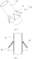
- a branch stent includes at least a tubular body 10 and a skirt 20 sleeved outiside the tubular body 10.
- the skirt 20 includes a metal rack 21 and an overlay membrane 22 covering the metal rack 21. After the branch stent is implanted into the hole of the membrance-covered stent, the skirt 20 may fill the gap between the tubular body and the hole to prevent internal leakage.
- a mold rod 40 is firstly provided outside the tubular body 10. At least one inner membrane 221, a metal rack 21 and at least one layer of the outer mold 222 are then provided in turn on the mode rod 40. After that, the mold ord 40 and the skirt 20 thereon are heat-treated together, so that the inner membrane 221 and the outer mold 222 are fused and bonded to each other under a certain temperature and pressure. Referring to FIG.
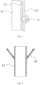
- the side of the skirt 20 engaged tightly to the mold rod 40 is flat and smooth, while the metal rack 21 protrudes from the side of the skirt 20 distant from the mold rod 40, so that the outer surface of the side of skirt 20 distant from the mold rod 40 is uneven.
- the prepared branch stent is directly disposed into the sheathing canal, as the outer surface of the skirt is uneven, it may easily scratch the inner wall of the sheathing canal. It may not only damage the skirt, but also may increase the friction between the skirt and the sheathing canal, leading to increase of the release force, making it difficult for the branch stent to come out of the sheath. Therefore, before disposing the branch stent into the sheathing canal, the skirt needs to be everted.
- the side of the skirt engaged tightly to the mold rod then becomes the outer surface of the skirt, which results in a skirt with a flat and smooth outer surface.
- some skirts cannot be everted, or may only be everted in case the skirt is stretched or bended, which damages the overlay membrane structure of the skirt.
- CN 202 875 531 U discloses an artificial blood vessel for an exclusion treatment inside an aortic aneurysm cavity.
- the artificial blood vessel comprises a bracket body.
- An intimal artificial vascular membrane is covered outside the bracket body.
- An outer artificial vascular membrane is further covered outside the intimal artificial vascular membrane at the near-end portion of the bracket body.
- a double-layer membrane cavity with enclosed periphery is formed at the near-end portion of the artificial blood vessel by the outer artificial vascular membrane and the intimal artificial vascular membrane.
- the present application is to provide a luminal stent that facilitats flanging in view of the defect in the prior art that the skirt may not easily be everted.
- implementing a luminal stent of the present application has the following beneficial effects: By adjusting the ratio of the distance between the fixed end and the free end on the same side of the tubular body to the vertical distance between the two fixed ends along the radial direction of the skirt, the skirt may evert without being stretched or bent under the condition of compressing the two fixed ends along the radial direction.
- a lumen is described by taking a blood vessel as an example, which may be an aortic arch, or a thoracic aorta, or an abdominal aorta.
- a blood vessel for illustration is only for exemplary purpose, and is not a limitation to the present application.
- the solution of the present application is applicable to various human lumens, such as the lumen of the alimentary canal, etc. Such improvements and modifications based on the teaching of the present application are all within the patentable scope of the present application.
- the directin may be defined according to the flow direction of blood , and the blood flow is defined as from the proximal end to the distal end in the present application.
- the radial support structure described in the present application refers to a closed waveform ring common in the art arranged along the axial direction of the membrane-covered stent.
- one of an exemplary embodiments of the present application provides a luminal stent 100,including a tubular body 10 and a skirt 20 sleeved outside the tubular body 10.
- the tubular body 10 is a tubular structure with an axial direction, which may serve as a new blood flow channel after being implanted in a blood vessel.
- the tubular body 10 includes at least a first radial support structure 11 and a first overlay membrane 12 covering the first radial support structure 11.
- the first radial support structure 11 fits with the first overlay membrane 12 to form the side wall of the tubular body 10.
- the first radial support structure 11 may be made of various biocompatible materials, such as nickel-titanium, stainless steel and the like.
- the first radial support structure 11 may include a plurality of turns of waveform rings in the axial direction, such as a plurality of turns of Z-shaped waves, M-shaped waves, or other structures that may be radially compressed to a small diameter; or include a spirally wound structure; or include a mesh structure.
- the first radial support structure 11 may be wound from a metal wire or cut from a metal tube.
- the first overlay membrane 12 is made of a polymer material with good biocompatibility, such as a PET membrane, a PTFE membrane, etc. The first overlay membrane 12 may cover on the first radial support structure 11 by means of sewing or hot melting.
- the tubular body 10 has a radial expansion capability, and may be compressed under an external force and may restore to and maintaine its original shape by self-expansion or by mechanical expansion (for example, balloon inflation) after the external force is withdrawn, whereby after the tubular body 10 is implanted into the lumen, it may be fixed in the lumen by engaging against the wall of the lumen by its radial support force. It should be noted that, unless otherwise specified, it is the initial shape of the luminal stent after radial deployment that is described herein.
- the tubular body 10 may isolate a diseased area of a lumen. For example, it may isolate an arterial dissection or an aneurysm after being implanted into an arterial blood vessel.
- the skirt 20 includes at least a second radial support structure 21 and a second overlay membrane 22 covering the second radial support structure 21.
- the second radial support structure 21 and the second overlay membrane 22 of the skirt 20 may be a same or similar radial support structure and overlay membrane as those of the above-mentioned tubular body 10, therefore, they will not be repeated here.
- the skirt 20 has radial expansion capability.
- One end of the skirt 20 is a fixed end 20a, and the fixed end 20a may be sealedly connected to the outer surface of the tubular body 10 by means of sewing or hot melting.
- the second overlay membrane 22 of the fixed end 20a may be thermally fused with the first overlay membrane 11 of the tubular body 10 together to achieve the sealed connection.
- the other end of the skirt 20 is a free end 20b, and the free end 20b is radiated outwards, so that the skirt 20 forms an approximately conical structure, that is, the cross section of the skirt 20 gradually increases along the direction from the fixed end 20a to the free end 20b.
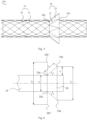
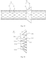
- the ratio of the distance L between the fixed end 20a and the free end 20b on the same side of the central axis of the tubular body 10 to the vertical distance D between the two free ends 20b along the radial direction of the skirt 20 is less than 1/2.
- the free end 20b turns around the fixed end 20a on the same side in a direction away from the tubular body 10, and the vertical distance h from the free end 20b to the outer surface of the tubular body 10 increases continuously.
- the vertical distance between the free end 20b' and the outer surface of the tubular body 10 reaches the maximum. At this time, the vertical distance between the two free ends 20b' in the radial direction of the skirt 20 is D'.
- the skirt 20 will not be elastically deformed.
- the vertical distance d between the two fixed ends 20a along the radial direction of the skirt 20 is constant, it is necessary to stretch the skirt 20 to gradually increase D to D ', or bend the skirt 20 so that the vertical distance h from the free end 20b to the outer surface of the tubular body 10 does not increase, but stretching or bending the skirt 20 will damage the overlay membrane structure of the skirt 20, leading to irreversible damage to the skirt 20.
- the two fixed ends 20a may be compressed radially so that D ' is not greater than D, that is, flanging without stretching or bending the skirt 20.
- the direction shown by the arrow in FIG 7 is the direction in which the two fixed ends 20a are compressed radially.
- the dotted line shows the schematic diagram of the luminal stent when the line connecting the free end 20b and the fixed end 20a on the same side is perpendicular to the central axis of the luminal stent after the two fixed ends 20a are compressed radially.
- the skirt 20 may evert without being stretched or bent when the two fixed ends 20a are compressed radially.
- the ratio of the vertical distance D between the two free ends 20b in the radial direction of the skirt 20 to the vertical distance d between the two fixed ends 20a in the radial direction of the skirt 20 is greater than or equal to 3/2. It should be noted that the vertical distance D between the two free ends 20b in the radial direction of the skirt 20 and the vertical distance d between the two fixed ends 20a in the radial direction of the skirt 20 are based on the initial shape after the radial expansion of the luminal stent.
- the skirt 20 is mainly used to fill the gap between the tubual body 10 and the hole of the membrane-covered stent to prevent internal leakage, if the ratio of the vertical distance D between the two free ends 20b along the radial direction of the skirt 20 to the vertical distance d between the two fixed ends 20a along the radial direction of the skirt 20 is too small, the skirt 20 may fail to completely fill the gap, leading to type III internal leakage.
- the included angle ⁇ between the connection line of the fixed end 20a and the free end 20b on the same side of the tubular body 10 and the center axis of the skirt 20 is too small, the included angle of the corresponding mold rod is also small, and the mold rod with a small included angle may not be easy to process. Therefore, to facilitate the processing, the included angle ⁇ between the connection line of the free end 20b and the fixed end 20a on the same side of the tubular body 10 and the center axis of the skirt 20 is not less than 30°. It may be appreciated that, in a section passing through the central axis of the skirt 20, the included angle ⁇ on both sides of the tubular body 10 may be the same or different.
- the tubular body 10 is shaped as a straight tube, and the skirt 20 is shaped as a frustum.
- the contour line of the skirt 20 is a straight line
- the vertical distance d between the two fixed ends 20a along the radial direction of the skirt 20 is the outer diameter of the tubular body 10.
- the contour line of the skirt 20 may also be an arc, a mixed line segment of a straight line and a straight line, a combined line segment of a straight line and an arc, or other irregular line segments.
- the contour line of the skirt 20 is arc-shaped.
- the contour line of the skirt 20 is a mixed line segment of a straight line and a straight line.
- the second radial support structure 21 includes at least one waveform ring 210, and each waveform ring 210 is a closed ring-shaped structure including a plurality of proximal vertices 211, a plurality of distal vertices 212, and a support 213 connecting the adjacent proximal vertex 211 and the distal vertex 212, and the proximal vertices 211 and the distal vertices 213 correspond to the peaks or troughs of the waveform, respectively.
- the second radial support structure 21 includes one waveform ring 210.
- the plurality of proximal vertices 211 of the waveform ring 210 are located in the same plane perpendicular to the central line of the skirt 20.
- the plurality of distal vertices 212 are also located in the same plane perpendicular to the central axis of the skirt 20.
- the second radial support structure 21 may further include a plurality of waveform rings 210.
- the a plurality of waveform rings 210 are sequentially arranged along the axial direction of the skirt 20, preferably arranged in parallel intervals, or the a plurality of waveform rings 210 are connected to form a mesh structure.
- the second radial support structure 21 may be distributed on a part of the skirt 20, that is, along the center axis direction of the skirt 20, and the maximum length of the two ends of the second radial support structure 21 is shorter than the length of the skirt 20.
- the second radial support structure 21 may also be distributed over the entire skirt 20, that is, along the center axis direction of the skirt 20, and the maximum length of the two ends of the second radial support structure 21 is equal to the length of the skirt 20.
- the second radial support structure 21 is distributed over the entire skirt 20.
- the end of the second radial support structure 21 close to the free end 20b is flush with the free end 20b of the skirt 20.
- the end of the second radial support structure 21 close to the fixed end 20a is flush with the fixed end 10a of the skirt 20.
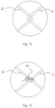
- the end of the second radial support structure 21 close to the fixed end 20a is rotatably connected to the first radial support structure 11 of the tubular body 10. Due to the poor mechanical behavior of the overlay membrane, if the skirt 20 and the tubular body 10 are connected only by the overlay membrane, the skirt 10 is easily pulled or deformed when flanging. It may increase the connection strength between the skirt 20 and the tubular body 10 by connecting the second radial support structure 21 to the first radial support structure 11, which in turn avoids the skirt 10 from being deformed or broken during the flanging, and also facilitates the eversion of the skirt.
- the present application does not limit the specific manner of the rotatable connection between the second radial support structure 21 and the first radial support structure 11. As shown in FIG 11 , at least one wave peak (or wave trough) of the second radial support structure 21 and at least one wave trough or (wave peak) of the first radial support structure 11 are hooked to each other.
- connection ring 30 which may be formed by winding with a flexible wire, or a metal ring made of a biocompatible material, such as nickel titanium, stainless steel and other materials.
- all the peaks (or troughs) of the side of the second radial support structure 21 close to the fixed end 20a are connected to the first radial support structure 11. It may be appreciated that, in other embodiments, a part of the peaks (or troughs) of the side of the second radial support structure 21 close to the fixed end 20a may be connected to the first radial support structure 11.
- the waveform ring 210 is approximately a frustum structure, and the waveform included angle a1 of the side of the waveform ring 210 close to the fixed end 20a is greater than the waveform included angle a2 of the side of the waveform ring 210 distant from the fixed end 20a. That is, the waveform angle a1 corresponding to the proximal vertex 211 is greater than the waveform angle a2 corresponding to the distal vertex 212.
- the waveform included angle refers to the included angle between the supports 104 connected on both sides of the same proximal vertex 102 or distal vertex 103.
- the a plurality of proximal vertices 211 of the waveform ring 210 converge toward one side of the central axis of the skirt 20.
- the waveform included angle a2 corresponding to the distal vertex 212 of the waveform ring 210 gradually decreases, and tends to 0°.
- the waveform included angle a2 corresponding to the distal vertex 212 of the waveform ring 210 is about 10°-30°.
- the wire diameter of the waveform ring 210 is in a range of 0.05 mm to 0.15 mm, and e.g. ranging from 0.07 mm to 0.13 mm.
- a second one of exemplary embodiments of the present application provides a luminal stent, which is different from the first embodiment in the structure of the second radial support structure 21.
- the second radial support structure 21 includes a waveform ring 210 rotatably connected to the first radial support structure 11.
- the waveform ring 210 is a closed ring structure, which includes at least one first proximal vertex 211a, a plurality of second proximal vertices 211b, a plurality of distal vertices 212, and a support 213 connecting the adjacent first proximal vertex 211a and the distal vertex 212 or the adjacent second proximal vertex 211b and the distal vertex 212.
- the first proximal vertex 211a and the second proximal vertex 211b correspond to the peaks of the waveform
- the distal vertices 212 correspond to the troughs of the waveform.
- the first proximal vertex 211a extends to the fixed end 10a of the skirt 20 and is rotatably connected to the first radial support structure 11.
- the distance between the first proximal vertex 211a and the reference distal vertex is greater than the distance between the second proximal vertex 211b and the reference distal vertex, and the included angle connected between the supports 104 to both sides of the first proximal vertex 211a is smaller than the included angle between the supports 104 connected to both sides of the second proximal vertex 211b.
- the wave height of the waveform ring 210 is constant, the greater the waveform included angle is, the greater the radial support force of the waveform ring 210 is, but if the waveform included angle is too large, it is not conducive to sheathing.
- the included angle of the wave ring 210 is constant, the smaller the wave height is, the larger the radial support force corresponding to the wave ring 210 is, but if the wave height is too small, it is not possible to maintain the roundness of the skirt 20, hindering the sealing effect of the skirt 20.
- the present application may increase the radial support force of the skirt 20 by providing a plurality of second proximal vertices 211b with relatively small wave heights and relatively large waveform included angles, while increasing the connection strength between the skirt 10 and the tubular body 20 by connecting the first proximal vertex 211a and the first support structure 11.
- the ratio of the distance between the first proximal vertex 211a and the reference distal vertex to the distance between the second proximal vertex 211b and the reference distal vertex is 0.3 to 0.8
- the included angle between supports 213 on both sides of the second proximal vertex 211b is 30° to 150°.
- the a plurality of distal vertices 212 of the waveform ring 210 are located in the same plane perpendicular to the central axis of the skirt 20 and are flush with the free end 20b of the skirt 20, and the first proximal vertex 211a extends to the fixed end 10a of the skirt 20, and is rotatably connected to the first radial support structure 11.
- the present application does not limit the specific number of the first proximal vertex 211a, and the first proximal vertex 211a may include one or more vertices.
- the first proximal vertex 211a includes a plurality of vertices
- the plurality of the first proximal vertices 211a are uniformly distributed along the circumferential direction of the skirt 21.
- the number of the first proximal vertices 211a is less than or equal to the number of the second proximal vertices 211b to increase the radial support force of the skirt 20.
- the second radial support structure 21 may further include other waveform ring structures, spirally wound structures or mesh structures.
Landscapes
- Health & Medical Sciences (AREA)
- Engineering & Computer Science (AREA)
- Biomedical Technology (AREA)
- Cardiology (AREA)
- Oral & Maxillofacial Surgery (AREA)
- Transplantation (AREA)
- Heart & Thoracic Surgery (AREA)
- Vascular Medicine (AREA)
- Life Sciences & Earth Sciences (AREA)
- Animal Behavior & Ethology (AREA)
- General Health & Medical Sciences (AREA)
- Public Health (AREA)
- Veterinary Medicine (AREA)
- Gastroenterology & Hepatology (AREA)
- Pulmonology (AREA)
- Prostheses (AREA)
Claims (12)
- Endoprothèse luminale (100), comprenant un corps tubulaire (10) et une jupe (20) emmanchée sur le corps tubulaire, une extrémité de la jupe est une extrémité fixe (20a) raccordée de manière étanche à la surface extérieure du corps tubulaire, l'autre extrémité de la jupe est une extrémité libre (20b), dans laquelle sur une section traversant l'axe central du corps tubulaire, le rapport entre la distance (L) entre l'extrémité fixe et l'extrémité libre situées sur le même côté de l'axe central du corps tubulaire et la distance verticale (D) des extrémités libres situées sur les deux côtés de l'axe central du corps tubulaire dans la direction radiale de la jupe est inférieur à 1/2, dans laquelle le corps tubulaire comprend une première structure de support radial (11) et une première membrane de recouvrement (12) couvrant la première structure de support radial, dans laquelle la jupe comprend une deuxième structure de support radial (21) et une deuxième membrane de recouvrement (22) couvrant la deuxième structure de support radial, et la deuxième structure de support radial est raccordée en rotation à la première structure de support radial, et dans laquelle les extrémités fixes (20a) de la jupe sont radialement comprimables pendant retournement de la jupe de sorte que, pendant retournement de la jupe, la distance verticale maximale (D') entre les extrémités libres dans la direction radiale n'est pas supérieure à la distance verticale (D) des extrémités libres lorsque la jupe n'est pas éversée.
- Endoprothèse luminale selon la revendication 1, dans laquelle le long de la direction radiale de la jupe (20), le rapport entre la distance verticale (D) entre les extrémités libres (20b) sur les deux côtés de l'axe central du corps tubulaire (10) et la distance verticale (d) des extrémités fixes (20a) sur les deux côtés de l'axe central du corps tubulaire est supérieur ou égal à 3/2.
- Endoprothèse luminale selon la revendication 1, dans laquelle l'angle inclus (α) entre la ligne reliant l'extrémité libre (20b) et l'extrémité fixe (20a) sur le même côté de l'axe central du corps tubulaire (10) et l'axe central du corps tubulaire n'est pas inférieur à 30 degrés.
- Endoprothèse luminale selon la revendication 1, dans laquelle la deuxième structure de support radial (21) comprend au moins un anneau sinusoïdal (210) ayant une pluralité de sommets proximaux (211), une pluralité de sommets distaux (212) et un support (213) raccordant le sommet proximal adjacent et le sommet distal, l'anneau sinusoïdal est raccordé en rotation à la première structure de support radial (11) à une position d'au moins l'un des sommets proximaux.
- Endoprothèse luminale selon la revendication 4, dans laquelle l'angle inclus (a1) entre les supports raccordés sur les deux côtés des sommets proximaux (211) est supérieur à l'angle inclus (a2) des supports raccordés sur les deux côtés des sommets distaux (212).
- Endoprothèse luminale selon la revendication 4, dans laquelle la pluralité de sommets proximaux comprend au moins un premier sommet proximal (211a) et une pluralité de deuxièmes sommets proximaux (211b), et l'anneau sinusoïdal (210) est raccordé en rotation à la première structure de support radial au niveau du premier sommet proximal.
- Endoprothèse luminale selon la revendication 6, dans laquelle la distance entre le premier sommet proximal (211a) et le sommet distal (211) est supérieure à la distance entre le deuxième sommet proximal (211b) et le sommet distal (211).
- Endoprothèse luminale selon la revendication 6, dans laquelle l'angle inclus entre les supports (104) raccordés sur les deux côtés du premier sommet proximal (211a) est inférieur à l'angle inclus des supports (104) raccordés sur les deux côtés du deuxième sommet proximal (211b).
- Endoprothèse luminale selon la revendication 4, dans laquelle les sommets distaux (212) sont situés dans le même plan perpendiculairement à l'axe central de la jupe (20).
- Endoprothèse luminale selon la revendication 4, dans laquelle l'angle inclus (a2) entre les supports raccordés sur les deux côtés du sommet distal (212) est d'environ 10 degrés à 30 degrés.
- Endoprothèse luminale selon la revendication 4, dans laquelle le diamètre de fil de l'anneau sinusoïdal (210) est d'environ 0,05 mm à 0,15 mm.
- Endoprothèse luminale selon la revendication 1, dans laquelle la deuxième structure de support radial (21) et la première structure de support radial (11) sont accrochées l'une à l'autre ou raccordées par l'intermédiaire d'un anneau de raccordement (30).
Applications Claiming Priority (2)
| Application Number | Priority Date | Filing Date | Title |
|---|---|---|---|
| CN201711461875.1A CN109966033B (zh) | 2017-12-28 | 2017-12-28 | 管腔支架 |
| PCT/CN2018/121744 WO2019128780A1 (fr) | 2017-12-28 | 2018-12-18 | Stent luminal |
Publications (3)
| Publication Number | Publication Date |
|---|---|
| EP3733127A1 EP3733127A1 (fr) | 2020-11-04 |
| EP3733127A4 EP3733127A4 (fr) | 2021-03-10 |
| EP3733127B1 true EP3733127B1 (fr) | 2024-02-07 |
Family
ID=67066542
Family Applications (1)
| Application Number | Title | Priority Date | Filing Date |
|---|---|---|---|
| EP18897682.3A Active EP3733127B1 (fr) | 2017-12-28 | 2018-12-18 | Stent luminal |
Country Status (5)
| Country | Link |
|---|---|
| US (1) | US12220332B2 (fr) |
| EP (1) | EP3733127B1 (fr) |
| CN (1) | CN109966033B (fr) |
| ES (1) | ES2973836T3 (fr) |
| WO (1) | WO2019128780A1 (fr) |
Families Citing this family (6)
| Publication number | Priority date | Publication date | Assignee | Title |
|---|---|---|---|---|
| CN112823766B (zh) * | 2019-11-21 | 2022-12-20 | 深圳市先健畅通医疗有限公司 | 双层管腔支架 |
| CN113855349B (zh) * | 2020-06-29 | 2023-11-17 | 先健科技(深圳)有限公司 | 管腔支架 |
| CN114681116B (zh) * | 2020-12-30 | 2025-07-18 | 先健科技(深圳)有限公司 | 管腔支架 |
| CN113558710B (zh) * | 2021-09-22 | 2022-01-25 | 北京华脉泰科医疗器械股份有限公司 | 瘤腔内密封支架 |
| KR102754821B1 (ko) * | 2023-05-24 | 2025-01-21 | (주)태웅메디칼 | 이탈 방지용 스텐트 |
| CN117426808B (zh) * | 2023-12-21 | 2024-03-08 | 北京华脉泰科医疗器械股份有限公司 | 裙边结构、自适应裙边支架、封堵器和裙边制作方法 |
Family Cites Families (19)
| Publication number | Priority date | Publication date | Assignee | Title |
|---|---|---|---|---|
| EP0556940A1 (fr) * | 1986-02-24 | 1993-08-25 | Robert E. Fischell | Stent intravasculaire |
| US6729356B1 (en) * | 2000-04-27 | 2004-05-04 | Endovascular Technologies, Inc. | Endovascular graft for providing a seal with vasculature |
| CN2486128Y (zh) * | 2001-06-13 | 2002-04-17 | 徐林 | 腔静脉滤器 |
| US7044962B2 (en) * | 2002-06-25 | 2006-05-16 | Scimed Life Systems, Inc. | Implantable prosthesis with displaceable skirt |
| KR101377117B1 (ko) * | 2006-07-19 | 2014-03-21 | 노베이트 메디칼 리미티드 | 혈관 필터 |
| US20090270971A1 (en) * | 2008-04-24 | 2009-10-29 | Medtronic Vascular, Inc. | Prosthesis Fixation Apparatus and Methods |
| US20100121424A1 (en) * | 2008-11-12 | 2010-05-13 | Petr Kubena | Stent compression tool |
| US8870938B2 (en) * | 2009-06-23 | 2014-10-28 | Endospan Ltd. | Vascular prostheses for treating aneurysms |
| US20120179236A1 (en) * | 2009-07-14 | 2012-07-12 | Endospan Ltd. | Sideport engagement and sealing mechanism for endoluminal stent-grafts |
| CN202270043U (zh) * | 2011-09-15 | 2012-06-13 | 李潮 | 动脉腔内支架 |
| US10016271B2 (en) * | 2011-10-19 | 2018-07-10 | Twelve, Inc. | Prosthetic heart valve devices, prosthetic mitral valves and associated systems and methods |
| CN102499789A (zh) * | 2011-10-31 | 2012-06-20 | 淮安市西格玛医用实业有限公司 | 一种跨胃支架 |
| CN104135966A (zh) | 2012-02-27 | 2014-11-05 | 国立大学法人广岛大学 | 覆膜支架 |
| CN202875531U (zh) * | 2012-10-16 | 2013-04-17 | 高峰 | 主动脉瘤腔内隔绝治疗用人工血管 |
| CN204072390U (zh) * | 2014-08-29 | 2015-01-07 | 张学民 | 防止内漏的支架型人工血管 |
| US20160338823A1 (en) * | 2015-05-18 | 2016-11-24 | Indiana University Research And Technology Corporation | Juxtarenal stent and methods |
| CA3004821C (fr) * | 2015-11-12 | 2023-12-12 | Endospan Ltd. | Systemes d'endoprothese couverte avec jupe |
| CN109077836B (zh) | 2015-12-30 | 2021-01-22 | 先健科技(深圳)有限公司 | 管腔支架 |
| CN105496603B (zh) * | 2015-12-30 | 2018-11-06 | 先健科技(深圳)有限公司 | 管腔支架 |
-
2017
- 2017-12-28 CN CN201711461875.1A patent/CN109966033B/zh active Active
-
2018
- 2018-12-18 EP EP18897682.3A patent/EP3733127B1/fr active Active
- 2018-12-18 ES ES18897682T patent/ES2973836T3/es active Active
- 2018-12-18 WO PCT/CN2018/121744 patent/WO2019128780A1/fr not_active Ceased
- 2018-12-18 US US16/954,347 patent/US12220332B2/en active Active
Also Published As
| Publication number | Publication date |
|---|---|
| EP3733127A4 (fr) | 2021-03-10 |
| ES2973836T3 (es) | 2024-06-24 |
| CN109966033A (zh) | 2019-07-05 |
| WO2019128780A1 (fr) | 2019-07-04 |
| US20210093471A1 (en) | 2021-04-01 |
| EP3733127A1 (fr) | 2020-11-04 |
| US12220332B2 (en) | 2025-02-11 |
| CN109966033B (zh) | 2022-05-20 |
Similar Documents
| Publication | Publication Date | Title |
|---|---|---|
| EP3733127B1 (fr) | Stent luminal | |
| JP6697439B2 (ja) | 狭い可撓性ウェブにより連結された隣接要素を有するステント | |
| CN109419567B (zh) | 管腔支架 | |
| US8721704B2 (en) | Expandable stent with wrinkle-free elastomeric cover | |
| US9539121B2 (en) | Apparatus and methods for conduits and materials | |
| EP3162322B1 (fr) | Stent recouvert de type fourche | |
| CN109966018B (zh) | 覆膜支架 | |
| US12324735B2 (en) | Stent graft with variable coverage of wavy rings | |
| WO2019042202A1 (fr) | Stent recouvert | |
| CN108095858A (zh) | 防短缩覆膜支架及其制作方法 | |
| WO2019128701A1 (fr) | Endoprothèse couverte | |
| CN110420075B (zh) | 覆膜支架 | |
| CN113476175B (zh) | 一种血管支架 | |
| CN110547896A (zh) | 血管覆膜支架 | |
| CN119235502B (zh) | 管腔支架 | |
| CN111228001B (zh) | 管腔支架及原位开窗支架系统 | |
| CN209107678U (zh) | 血管覆膜支架 | |
| CN209405015U (zh) | 降低破口压力的覆膜支架 | |
| CN114681116B (zh) | 管腔支架 | |
| CN115052556A (zh) | 分支内置假体系统、设备和方法 | |
| CN112891033B (zh) | 管腔支架 | |
| CN110420074B (zh) | 覆膜支架 | |
| CN116725751A (zh) | 可调式支架 | |
| CN207384352U (zh) | 覆膜支架 | |
| CN110652377A (zh) | 覆膜支架和覆膜支架的制作方法 |
Legal Events
| Date | Code | Title | Description |
|---|---|---|---|
| STAA | Information on the status of an ep patent application or granted ep patent |
Free format text: STATUS: THE INTERNATIONAL PUBLICATION HAS BEEN MADE |
|
| PUAI | Public reference made under article 153(3) epc to a published international application that has entered the european phase |
Free format text: ORIGINAL CODE: 0009012 |
|
| STAA | Information on the status of an ep patent application or granted ep patent |
Free format text: STATUS: REQUEST FOR EXAMINATION WAS MADE |
|
| 17P | Request for examination filed |
Effective date: 20200702 |
|
| AK | Designated contracting states |
Kind code of ref document: A1 Designated state(s): AL AT BE BG CH CY CZ DE DK EE ES FI FR GB GR HR HU IE IS IT LI LT LU LV MC MK MT NL NO PL PT RO RS SE SI SK SM TR |
|
| AX | Request for extension of the european patent |
Extension state: BA ME |
|
| A4 | Supplementary search report drawn up and despatched |
Effective date: 20210208 |
|
| RIC1 | Information provided on ipc code assigned before grant |
Ipc: A61F 2/90 20130101ALN20210202BHEP Ipc: A61F 2/07 20130101AFI20210202BHEP |
|
| DAV | Request for validation of the european patent (deleted) | ||
| DAX | Request for extension of the european patent (deleted) | ||
| GRAP | Despatch of communication of intention to grant a patent |
Free format text: ORIGINAL CODE: EPIDOSNIGR1 |
|
| STAA | Information on the status of an ep patent application or granted ep patent |
Free format text: STATUS: GRANT OF PATENT IS INTENDED |
|
| INTG | Intention to grant announced |
Effective date: 20230830 |
|
| GRAS | Grant fee paid |
Free format text: ORIGINAL CODE: EPIDOSNIGR3 |
|
| GRAA | (expected) grant |
Free format text: ORIGINAL CODE: 0009210 |
|
| STAA | Information on the status of an ep patent application or granted ep patent |
Free format text: STATUS: THE PATENT HAS BEEN GRANTED |
|
| P01 | Opt-out of the competence of the unified patent court (upc) registered |
Effective date: 20231206 |
|
| AK | Designated contracting states |
Kind code of ref document: B1 Designated state(s): AL AT BE BG CH CY CZ DE DK EE ES FI FR GB GR HR HU IE IS IT LI LT LU LV MC MK MT NL NO PL PT RO RS SE SI SK SM TR |
|
| REG | Reference to a national code |
Ref country code: GB Ref legal event code: FG4D |
|
| REG | Reference to a national code |
Ref country code: CH Ref legal event code: EP |
|
| REG | Reference to a national code |
Ref country code: IE Ref legal event code: FG4D |
|
| REG | Reference to a national code |
Ref country code: DE Ref legal event code: R096 Ref document number: 602018065080 Country of ref document: DE |
|
| REG | Reference to a national code |
Ref country code: LT Ref legal event code: MG9D |
|
| REG | Reference to a national code |
Ref country code: NL Ref legal event code: MP Effective date: 20240207 |
|
| REG | Reference to a national code |
Ref country code: ES Ref legal event code: FG2A Ref document number: 2973836 Country of ref document: ES Kind code of ref document: T3 Effective date: 20240624 |
|
| PG25 | Lapsed in a contracting state [announced via postgrant information from national office to epo] |
Ref country code: IS Free format text: LAPSE BECAUSE OF FAILURE TO SUBMIT A TRANSLATION OF THE DESCRIPTION OR TO PAY THE FEE WITHIN THE PRESCRIBED TIME-LIMIT Effective date: 20240607 |
|
| PG25 | Lapsed in a contracting state [announced via postgrant information from national office to epo] |
Ref country code: LT Free format text: LAPSE BECAUSE OF FAILURE TO SUBMIT A TRANSLATION OF THE DESCRIPTION OR TO PAY THE FEE WITHIN THE PRESCRIBED TIME-LIMIT Effective date: 20240207 |
|
| PG25 | Lapsed in a contracting state [announced via postgrant information from national office to epo] |
Ref country code: GR Free format text: LAPSE BECAUSE OF FAILURE TO SUBMIT A TRANSLATION OF THE DESCRIPTION OR TO PAY THE FEE WITHIN THE PRESCRIBED TIME-LIMIT Effective date: 20240508 |
|
| REG | Reference to a national code |
Ref country code: AT Ref legal event code: MK05 Ref document number: 1654889 Country of ref document: AT Kind code of ref document: T Effective date: 20240207 |
|
| PG25 | Lapsed in a contracting state [announced via postgrant information from national office to epo] |
Ref country code: NL Free format text: LAPSE BECAUSE OF FAILURE TO SUBMIT A TRANSLATION OF THE DESCRIPTION OR TO PAY THE FEE WITHIN THE PRESCRIBED TIME-LIMIT Effective date: 20240207 Ref country code: HR Free format text: LAPSE BECAUSE OF FAILURE TO SUBMIT A TRANSLATION OF THE DESCRIPTION OR TO PAY THE FEE WITHIN THE PRESCRIBED TIME-LIMIT Effective date: 20240207 Ref country code: RS Free format text: LAPSE BECAUSE OF FAILURE TO SUBMIT A TRANSLATION OF THE DESCRIPTION OR TO PAY THE FEE WITHIN THE PRESCRIBED TIME-LIMIT Effective date: 20240507 |
|
| PG25 | Lapsed in a contracting state [announced via postgrant information from national office to epo] |
Ref country code: AT Free format text: LAPSE BECAUSE OF FAILURE TO SUBMIT A TRANSLATION OF THE DESCRIPTION OR TO PAY THE FEE WITHIN THE PRESCRIBED TIME-LIMIT Effective date: 20240207 |
|
| PG25 | Lapsed in a contracting state [announced via postgrant information from national office to epo] |
Ref country code: RS Free format text: LAPSE BECAUSE OF FAILURE TO SUBMIT A TRANSLATION OF THE DESCRIPTION OR TO PAY THE FEE WITHIN THE PRESCRIBED TIME-LIMIT Effective date: 20240507 Ref country code: NO Free format text: LAPSE BECAUSE OF FAILURE TO SUBMIT A TRANSLATION OF THE DESCRIPTION OR TO PAY THE FEE WITHIN THE PRESCRIBED TIME-LIMIT Effective date: 20240507 Ref country code: NL Free format text: LAPSE BECAUSE OF FAILURE TO SUBMIT A TRANSLATION OF THE DESCRIPTION OR TO PAY THE FEE WITHIN THE PRESCRIBED TIME-LIMIT Effective date: 20240207 Ref country code: LT Free format text: LAPSE BECAUSE OF FAILURE TO SUBMIT A TRANSLATION OF THE DESCRIPTION OR TO PAY THE FEE WITHIN THE PRESCRIBED TIME-LIMIT Effective date: 20240207 Ref country code: IS Free format text: LAPSE BECAUSE OF FAILURE TO SUBMIT A TRANSLATION OF THE DESCRIPTION OR TO PAY THE FEE WITHIN THE PRESCRIBED TIME-LIMIT Effective date: 20240607 Ref country code: HR Free format text: LAPSE BECAUSE OF FAILURE TO SUBMIT A TRANSLATION OF THE DESCRIPTION OR TO PAY THE FEE WITHIN THE PRESCRIBED TIME-LIMIT Effective date: 20240207 Ref country code: GR Free format text: LAPSE BECAUSE OF FAILURE TO SUBMIT A TRANSLATION OF THE DESCRIPTION OR TO PAY THE FEE WITHIN THE PRESCRIBED TIME-LIMIT Effective date: 20240508 Ref country code: FI Free format text: LAPSE BECAUSE OF FAILURE TO SUBMIT A TRANSLATION OF THE DESCRIPTION OR TO PAY THE FEE WITHIN THE PRESCRIBED TIME-LIMIT Effective date: 20240207 Ref country code: BG Free format text: LAPSE BECAUSE OF FAILURE TO SUBMIT A TRANSLATION OF THE DESCRIPTION OR TO PAY THE FEE WITHIN THE PRESCRIBED TIME-LIMIT Effective date: 20240207 Ref country code: AT Free format text: LAPSE BECAUSE OF FAILURE TO SUBMIT A TRANSLATION OF THE DESCRIPTION OR TO PAY THE FEE WITHIN THE PRESCRIBED TIME-LIMIT Effective date: 20240207 |
|
| PG25 | Lapsed in a contracting state [announced via postgrant information from national office to epo] |
Ref country code: PL Free format text: LAPSE BECAUSE OF FAILURE TO SUBMIT A TRANSLATION OF THE DESCRIPTION OR TO PAY THE FEE WITHIN THE PRESCRIBED TIME-LIMIT Effective date: 20240207 Ref country code: PT Free format text: LAPSE BECAUSE OF FAILURE TO SUBMIT A TRANSLATION OF THE DESCRIPTION OR TO PAY THE FEE WITHIN THE PRESCRIBED TIME-LIMIT Effective date: 20240607 |
|
| PG25 | Lapsed in a contracting state [announced via postgrant information from national office to epo] |
Ref country code: SE Free format text: LAPSE BECAUSE OF FAILURE TO SUBMIT A TRANSLATION OF THE DESCRIPTION OR TO PAY THE FEE WITHIN THE PRESCRIBED TIME-LIMIT Effective date: 20240207 Ref country code: PT Free format text: LAPSE BECAUSE OF FAILURE TO SUBMIT A TRANSLATION OF THE DESCRIPTION OR TO PAY THE FEE WITHIN THE PRESCRIBED TIME-LIMIT Effective date: 20240607 Ref country code: PL Free format text: LAPSE BECAUSE OF FAILURE TO SUBMIT A TRANSLATION OF THE DESCRIPTION OR TO PAY THE FEE WITHIN THE PRESCRIBED TIME-LIMIT Effective date: 20240207 Ref country code: LV Free format text: LAPSE BECAUSE OF FAILURE TO SUBMIT A TRANSLATION OF THE DESCRIPTION OR TO PAY THE FEE WITHIN THE PRESCRIBED TIME-LIMIT Effective date: 20240207 |
|
| PG25 | Lapsed in a contracting state [announced via postgrant information from national office to epo] |
Ref country code: DK Free format text: LAPSE BECAUSE OF FAILURE TO SUBMIT A TRANSLATION OF THE DESCRIPTION OR TO PAY THE FEE WITHIN THE PRESCRIBED TIME-LIMIT Effective date: 20240207 |
|
| PG25 | Lapsed in a contracting state [announced via postgrant information from national office to epo] |
Ref country code: SM Free format text: LAPSE BECAUSE OF FAILURE TO SUBMIT A TRANSLATION OF THE DESCRIPTION OR TO PAY THE FEE WITHIN THE PRESCRIBED TIME-LIMIT Effective date: 20240207 |
|
| PG25 | Lapsed in a contracting state [announced via postgrant information from national office to epo] |
Ref country code: CZ Free format text: LAPSE BECAUSE OF FAILURE TO SUBMIT A TRANSLATION OF THE DESCRIPTION OR TO PAY THE FEE WITHIN THE PRESCRIBED TIME-LIMIT Effective date: 20240207 Ref country code: EE Free format text: LAPSE BECAUSE OF FAILURE TO SUBMIT A TRANSLATION OF THE DESCRIPTION OR TO PAY THE FEE WITHIN THE PRESCRIBED TIME-LIMIT Effective date: 20240207 |
|
| PG25 | Lapsed in a contracting state [announced via postgrant information from national office to epo] |
Ref country code: SK Free format text: LAPSE BECAUSE OF FAILURE TO SUBMIT A TRANSLATION OF THE DESCRIPTION OR TO PAY THE FEE WITHIN THE PRESCRIBED TIME-LIMIT Effective date: 20240207 |
|
| PG25 | Lapsed in a contracting state [announced via postgrant information from national office to epo] |
Ref country code: SM Free format text: LAPSE BECAUSE OF FAILURE TO SUBMIT A TRANSLATION OF THE DESCRIPTION OR TO PAY THE FEE WITHIN THE PRESCRIBED TIME-LIMIT Effective date: 20240207 Ref country code: SK Free format text: LAPSE BECAUSE OF FAILURE TO SUBMIT A TRANSLATION OF THE DESCRIPTION OR TO PAY THE FEE WITHIN THE PRESCRIBED TIME-LIMIT Effective date: 20240207 Ref country code: RO Free format text: LAPSE BECAUSE OF FAILURE TO SUBMIT A TRANSLATION OF THE DESCRIPTION OR TO PAY THE FEE WITHIN THE PRESCRIBED TIME-LIMIT Effective date: 20240207 Ref country code: EE Free format text: LAPSE BECAUSE OF FAILURE TO SUBMIT A TRANSLATION OF THE DESCRIPTION OR TO PAY THE FEE WITHIN THE PRESCRIBED TIME-LIMIT Effective date: 20240207 Ref country code: DK Free format text: LAPSE BECAUSE OF FAILURE TO SUBMIT A TRANSLATION OF THE DESCRIPTION OR TO PAY THE FEE WITHIN THE PRESCRIBED TIME-LIMIT Effective date: 20240207 Ref country code: CZ Free format text: LAPSE BECAUSE OF FAILURE TO SUBMIT A TRANSLATION OF THE DESCRIPTION OR TO PAY THE FEE WITHIN THE PRESCRIBED TIME-LIMIT Effective date: 20240207 |
|
| REG | Reference to a national code |
Ref country code: DE Ref legal event code: R097 Ref document number: 602018065080 Country of ref document: DE |
|
| PG25 | Lapsed in a contracting state [announced via postgrant information from national office to epo] |
Ref country code: IT Free format text: LAPSE BECAUSE OF FAILURE TO SUBMIT A TRANSLATION OF THE DESCRIPTION OR TO PAY THE FEE WITHIN THE PRESCRIBED TIME-LIMIT Effective date: 20240207 |
|
| PLBE | No opposition filed within time limit |
Free format text: ORIGINAL CODE: 0009261 |
|
| STAA | Information on the status of an ep patent application or granted ep patent |
Free format text: STATUS: NO OPPOSITION FILED WITHIN TIME LIMIT |
|
| PG25 | Lapsed in a contracting state [announced via postgrant information from national office to epo] |
Ref country code: IT Free format text: LAPSE BECAUSE OF FAILURE TO SUBMIT A TRANSLATION OF THE DESCRIPTION OR TO PAY THE FEE WITHIN THE PRESCRIBED TIME-LIMIT Effective date: 20240207 |
|
| 26N | No opposition filed |
Effective date: 20241108 |
|
| PG25 | Lapsed in a contracting state [announced via postgrant information from national office to epo] |
Ref country code: SI Free format text: LAPSE BECAUSE OF FAILURE TO SUBMIT A TRANSLATION OF THE DESCRIPTION OR TO PAY THE FEE WITHIN THE PRESCRIBED TIME-LIMIT Effective date: 20240207 |
|
| PG25 | Lapsed in a contracting state [announced via postgrant information from national office to epo] |
Ref country code: MC Free format text: LAPSE BECAUSE OF FAILURE TO SUBMIT A TRANSLATION OF THE DESCRIPTION OR TO PAY THE FEE WITHIN THE PRESCRIBED TIME-LIMIT Effective date: 20240207 |
|
| REG | Reference to a national code |
Ref country code: CH Ref legal event code: PL |
|
| PG25 | Lapsed in a contracting state [announced via postgrant information from national office to epo] |
Ref country code: LU Free format text: LAPSE BECAUSE OF NON-PAYMENT OF DUE FEES Effective date: 20241218 |
|
| GBPC | Gb: european patent ceased through non-payment of renewal fee |
Effective date: 20241218 |
|
| REG | Reference to a national code |
Ref country code: BE Ref legal event code: MM Effective date: 20241231 |
|
| PG25 | Lapsed in a contracting state [announced via postgrant information from national office to epo] |
Ref country code: GB Free format text: LAPSE BECAUSE OF NON-PAYMENT OF DUE FEES Effective date: 20241218 Ref country code: BE Free format text: LAPSE BECAUSE OF NON-PAYMENT OF DUE FEES Effective date: 20241231 |
|
| PG25 | Lapsed in a contracting state [announced via postgrant information from national office to epo] |
Ref country code: CH Free format text: LAPSE BECAUSE OF NON-PAYMENT OF DUE FEES Effective date: 20241231 |
|
| PG25 | Lapsed in a contracting state [announced via postgrant information from national office to epo] |
Ref country code: IE Free format text: LAPSE BECAUSE OF NON-PAYMENT OF DUE FEES Effective date: 20241218 |
|
| PGFP | Annual fee paid to national office [announced via postgrant information from national office to epo] |
Ref country code: FR Payment date: 20251230 Year of fee payment: 8 |
|
| PGFP | Annual fee paid to national office [announced via postgrant information from national office to epo] |
Ref country code: ES Payment date: 20260112 Year of fee payment: 8 |
|
| PGFP | Annual fee paid to national office [announced via postgrant information from national office to epo] |
Ref country code: DE Payment date: 20251231 Year of fee payment: 8 |