EP3733301A1 - Vorformbeschichtungsvorrichtung - Google Patents
Vorformbeschichtungsvorrichtung Download PDFInfo
- Publication number
- EP3733301A1 EP3733301A1 EP18895710.4A EP18895710A EP3733301A1 EP 3733301 A1 EP3733301 A1 EP 3733301A1 EP 18895710 A EP18895710 A EP 18895710A EP 3733301 A1 EP3733301 A1 EP 3733301A1
- Authority
- EP
- European Patent Office
- Prior art keywords
- preform
- dryer
- coating solution
- blower mechanism
- flow rate
- Prior art date
- Legal status (The legal status is an assumption and is not a legal conclusion. Google has not performed a legal analysis and makes no representation as to the accuracy of the status listed.)
- Withdrawn
Links
- 239000011248 coating agent Substances 0.000 title claims abstract description 149
- 238000000576 coating method Methods 0.000 title claims abstract description 148
- 230000007246 mechanism Effects 0.000 claims abstract description 106
- 230000001678 irradiating effect Effects 0.000 claims abstract description 4
- 238000007599 discharging Methods 0.000 claims description 3
- 239000007788 liquid Substances 0.000 abstract 3
- 230000002401 inhibitory effect Effects 0.000 abstract 1
- 230000000630 rising effect Effects 0.000 abstract 1
- 239000000243 solution Substances 0.000 description 95
- 239000007789 gas Substances 0.000 description 38
- 229920003023 plastic Polymers 0.000 description 23
- 239000004033 plastic Substances 0.000 description 23
- 238000001035 drying Methods 0.000 description 20
- 230000004888 barrier function Effects 0.000 description 16
- 230000014759 maintenance of location Effects 0.000 description 15
- 230000002093 peripheral effect Effects 0.000 description 11
- 238000007664 blowing Methods 0.000 description 9
- 230000002087 whitening effect Effects 0.000 description 7
- 229920000139 polyethylene terephthalate Polymers 0.000 description 6
- 239000005020 polyethylene terephthalate Substances 0.000 description 6
- 238000000465 moulding Methods 0.000 description 5
- -1 polyethylene terephthalate Polymers 0.000 description 5
- CURLTUGMZLYLDI-UHFFFAOYSA-N Carbon dioxide Chemical compound O=C=O CURLTUGMZLYLDI-UHFFFAOYSA-N 0.000 description 4
- 239000004372 Polyvinyl alcohol Substances 0.000 description 4
- 230000005540 biological transmission Effects 0.000 description 4
- 238000000071 blow moulding Methods 0.000 description 4
- 229920002451 polyvinyl alcohol Polymers 0.000 description 4
- 239000011253 protective coating Substances 0.000 description 4
- 229920005989 resin Polymers 0.000 description 4
- 239000011347 resin Substances 0.000 description 4
- 230000000694 effects Effects 0.000 description 3
- 230000000717 retained effect Effects 0.000 description 3
- 229920000219 Ethylene vinyl alcohol Polymers 0.000 description 2
- 229930040373 Paraformaldehyde Natural products 0.000 description 2
- 239000004698 Polyethylene Substances 0.000 description 2
- 239000004743 Polypropylene Substances 0.000 description 2
- QVGXLLKOCUKJST-UHFFFAOYSA-N atomic oxygen Chemical compound [O] QVGXLLKOCUKJST-UHFFFAOYSA-N 0.000 description 2
- 235000013361 beverage Nutrition 0.000 description 2
- 229910002092 carbon dioxide Inorganic materials 0.000 description 2
- 239000001569 carbon dioxide Substances 0.000 description 2
- 230000008859 change Effects 0.000 description 2
- 230000000052 comparative effect Effects 0.000 description 2
- 239000006185 dispersion Substances 0.000 description 2
- 230000005484 gravity Effects 0.000 description 2
- 239000002184 metal Substances 0.000 description 2
- 238000000034 method Methods 0.000 description 2
- 229910052760 oxygen Inorganic materials 0.000 description 2
- 239000001301 oxygen Substances 0.000 description 2
- 229920002037 poly(vinyl butyral) polymer Polymers 0.000 description 2
- 229920000573 polyethylene Polymers 0.000 description 2
- 229920000098 polyolefin Polymers 0.000 description 2
- 229920006324 polyoxymethylene Polymers 0.000 description 2
- 229920001155 polypropylene Polymers 0.000 description 2
- 229910001220 stainless steel Inorganic materials 0.000 description 2
- 239000010935 stainless steel Substances 0.000 description 2
- OKTJSMMVPCPJKN-UHFFFAOYSA-N Carbon Chemical compound [C] OKTJSMMVPCPJKN-UHFFFAOYSA-N 0.000 description 1
- 239000004952 Polyamide Substances 0.000 description 1
- 229920000954 Polyglycolide Polymers 0.000 description 1
- 230000015572 biosynthetic process Effects 0.000 description 1
- 229910052799 carbon Inorganic materials 0.000 description 1
- 239000011247 coating layer Substances 0.000 description 1
- 238000000748 compression moulding Methods 0.000 description 1
- 238000001816 cooling Methods 0.000 description 1
- 230000007547 defect Effects 0.000 description 1
- 239000004715 ethylene vinyl alcohol Substances 0.000 description 1
- 238000010438 heat treatment Methods 0.000 description 1
- 238000001746 injection moulding Methods 0.000 description 1
- 229910010272 inorganic material Inorganic materials 0.000 description 1
- 239000011147 inorganic material Substances 0.000 description 1
- 230000004048 modification Effects 0.000 description 1
- 238000012986 modification Methods 0.000 description 1
- 230000035515 penetration Effects 0.000 description 1
- 229920002239 polyacrylonitrile Polymers 0.000 description 1
- 229920002647 polyamide Polymers 0.000 description 1
- 229920000728 polyester Polymers 0.000 description 1
- 239000004633 polyglycolic acid Substances 0.000 description 1
- 239000005033 polyvinylidene chloride Substances 0.000 description 1
- 239000013589 supplement Substances 0.000 description 1
- 238000011144 upstream manufacturing Methods 0.000 description 1
Images


Classifications
-
- B—PERFORMING OPERATIONS; TRANSPORTING
- B29—WORKING OF PLASTICS; WORKING OF SUBSTANCES IN A PLASTIC STATE IN GENERAL
- B29B—PREPARATION OR PRETREATMENT OF THE MATERIAL TO BE SHAPED; MAKING GRANULES OR PREFORMS; RECOVERY OF PLASTICS OR OTHER CONSTITUENTS OF WASTE MATERIAL CONTAINING PLASTICS
- B29B11/00—Making preforms
- B29B11/14—Making preforms characterised by structure or composition
-
- B—PERFORMING OPERATIONS; TRANSPORTING
- B05—SPRAYING OR ATOMISING IN GENERAL; APPLYING FLUENT MATERIALS TO SURFACES, IN GENERAL
- B05C—APPARATUS FOR APPLYING FLUENT MATERIALS TO SURFACES, IN GENERAL
- B05C13/00—Means for manipulating or holding work, e.g. for separate articles
- B05C13/02—Means for manipulating or holding work, e.g. for separate articles for particular articles
-
- B—PERFORMING OPERATIONS; TRANSPORTING
- B05—SPRAYING OR ATOMISING IN GENERAL; APPLYING FLUENT MATERIALS TO SURFACES, IN GENERAL
- B05C—APPARATUS FOR APPLYING FLUENT MATERIALS TO SURFACES, IN GENERAL
- B05C5/00—Apparatus in which liquid or other fluent material is projected, poured or allowed to flow on to the surface of the work
- B05C5/001—Apparatus in which liquid or other fluent material is projected, poured or allowed to flow on to the surface of the work incorporating means for heating or cooling the liquid or other fluent material
-
- B—PERFORMING OPERATIONS; TRANSPORTING
- B05—SPRAYING OR ATOMISING IN GENERAL; APPLYING FLUENT MATERIALS TO SURFACES, IN GENERAL
- B05D—PROCESSES FOR APPLYING FLUENT MATERIALS TO SURFACES, IN GENERAL
- B05D3/00—Pretreatment of surfaces to which liquids or other fluent materials are to be applied; After-treatment of applied coatings, e.g. intermediate treating of an applied coating preparatory to subsequent applications of liquids or other fluent materials
- B05D3/02—Pretreatment of surfaces to which liquids or other fluent materials are to be applied; After-treatment of applied coatings, e.g. intermediate treating of an applied coating preparatory to subsequent applications of liquids or other fluent materials by baking
- B05D3/0254—After-treatment
- B05D3/0263—After-treatment with IR heaters
-
- B—PERFORMING OPERATIONS; TRANSPORTING
- B05—SPRAYING OR ATOMISING IN GENERAL; APPLYING FLUENT MATERIALS TO SURFACES, IN GENERAL
- B05D—PROCESSES FOR APPLYING FLUENT MATERIALS TO SURFACES, IN GENERAL
- B05D3/00—Pretreatment of surfaces to which liquids or other fluent materials are to be applied; After-treatment of applied coatings, e.g. intermediate treating of an applied coating preparatory to subsequent applications of liquids or other fluent materials
- B05D3/04—Pretreatment of surfaces to which liquids or other fluent materials are to be applied; After-treatment of applied coatings, e.g. intermediate treating of an applied coating preparatory to subsequent applications of liquids or other fluent materials by exposure to gases
- B05D3/0406—Pretreatment of surfaces to which liquids or other fluent materials are to be applied; After-treatment of applied coatings, e.g. intermediate treating of an applied coating preparatory to subsequent applications of liquids or other fluent materials by exposure to gases the gas being air
- B05D3/0426—Cooling with air
-
- B—PERFORMING OPERATIONS; TRANSPORTING
- B05—SPRAYING OR ATOMISING IN GENERAL; APPLYING FLUENT MATERIALS TO SURFACES, IN GENERAL
- B05D—PROCESSES FOR APPLYING FLUENT MATERIALS TO SURFACES, IN GENERAL
- B05D7/00—Processes, other than flocking, specially adapted for applying liquids or other fluent materials to particular surfaces or for applying particular liquids or other fluent materials
- B05D7/02—Processes, other than flocking, specially adapted for applying liquids or other fluent materials to particular surfaces or for applying particular liquids or other fluent materials to macromolecular substances, e.g. rubber
-
- B—PERFORMING OPERATIONS; TRANSPORTING
- B29—WORKING OF PLASTICS; WORKING OF SUBSTANCES IN A PLASTIC STATE IN GENERAL
- B29C—SHAPING OR JOINING OF PLASTICS; SHAPING OF MATERIAL IN A PLASTIC STATE, NOT OTHERWISE PROVIDED FOR; AFTER-TREATMENT OF THE SHAPED PRODUCTS, e.g. REPAIRING
- B29C49/00—Blow-moulding, i.e. blowing a preform or parison to a desired shape within a mould; Apparatus therefor
- B29C49/0005—Blow-moulding, i.e. blowing a preform or parison to a desired shape within a mould; Apparatus therefor characterised by the material
-
- B—PERFORMING OPERATIONS; TRANSPORTING
- B29—WORKING OF PLASTICS; WORKING OF SUBSTANCES IN A PLASTIC STATE IN GENERAL
- B29C—SHAPING OR JOINING OF PLASTICS; SHAPING OF MATERIAL IN A PLASTIC STATE, NOT OTHERWISE PROVIDED FOR; AFTER-TREATMENT OF THE SHAPED PRODUCTS, e.g. REPAIRING
- B29C49/00—Blow-moulding, i.e. blowing a preform or parison to a desired shape within a mould; Apparatus therefor
- B29C49/02—Combined blow-moulding and manufacture of the preform or the parison
-
- B—PERFORMING OPERATIONS; TRANSPORTING
- B29—WORKING OF PLASTICS; WORKING OF SUBSTANCES IN A PLASTIC STATE IN GENERAL
- B29C—SHAPING OR JOINING OF PLASTICS; SHAPING OF MATERIAL IN A PLASTIC STATE, NOT OTHERWISE PROVIDED FOR; AFTER-TREATMENT OF THE SHAPED PRODUCTS, e.g. REPAIRING
- B29C49/00—Blow-moulding, i.e. blowing a preform or parison to a desired shape within a mould; Apparatus therefor
- B29C49/071—Preforms or parisons characterised by their configuration, e.g. geometry, dimensions or physical properties
-
- B—PERFORMING OPERATIONS; TRANSPORTING
- B29—WORKING OF PLASTICS; WORKING OF SUBSTANCES IN A PLASTIC STATE IN GENERAL
- B29C—SHAPING OR JOINING OF PLASTICS; SHAPING OF MATERIAL IN A PLASTIC STATE, NOT OTHERWISE PROVIDED FOR; AFTER-TREATMENT OF THE SHAPED PRODUCTS, e.g. REPAIRING
- B29C49/00—Blow-moulding, i.e. blowing a preform or parison to a desired shape within a mould; Apparatus therefor
- B29C49/08—Biaxial stretching during blow-moulding
- B29C49/10—Biaxial stretching during blow-moulding using mechanical means for prestretching
- B29C49/12—Stretching rods
-
- B—PERFORMING OPERATIONS; TRANSPORTING
- B29—WORKING OF PLASTICS; WORKING OF SUBSTANCES IN A PLASTIC STATE IN GENERAL
- B29C—SHAPING OR JOINING OF PLASTICS; SHAPING OF MATERIAL IN A PLASTIC STATE, NOT OTHERWISE PROVIDED FOR; AFTER-TREATMENT OF THE SHAPED PRODUCTS, e.g. REPAIRING
- B29C49/00—Blow-moulding, i.e. blowing a preform or parison to a desired shape within a mould; Apparatus therefor
- B29C49/22—Blow-moulding, i.e. blowing a preform or parison to a desired shape within a mould; Apparatus therefor using multilayered preforms or parisons
-
- B—PERFORMING OPERATIONS; TRANSPORTING
- B05—SPRAYING OR ATOMISING IN GENERAL; APPLYING FLUENT MATERIALS TO SURFACES, IN GENERAL
- B05C—APPARATUS FOR APPLYING FLUENT MATERIALS TO SURFACES, IN GENERAL
- B05C5/00—Apparatus in which liquid or other fluent material is projected, poured or allowed to flow on to the surface of the work
- B05C5/02—Apparatus in which liquid or other fluent material is projected, poured or allowed to flow on to the surface of the work the liquid or other fluent material being discharged through an outlet orifice by pressure, e.g. from an outlet device in contact or almost in contact, with the work
- B05C5/0254—Coating heads with slot-shaped outlet
- B05C5/0262—Coating heads with slot-shaped outlet adjustable in width, i.e. having lips movable relative to each other in order to modify the slot width, e.g. to close it
-
- B—PERFORMING OPERATIONS; TRANSPORTING
- B05—SPRAYING OR ATOMISING IN GENERAL; APPLYING FLUENT MATERIALS TO SURFACES, IN GENERAL
- B05C—APPARATUS FOR APPLYING FLUENT MATERIALS TO SURFACES, IN GENERAL
- B05C5/00—Apparatus in which liquid or other fluent material is projected, poured or allowed to flow on to the surface of the work
- B05C5/02—Apparatus in which liquid or other fluent material is projected, poured or allowed to flow on to the surface of the work the liquid or other fluent material being discharged through an outlet orifice by pressure, e.g. from an outlet device in contact or almost in contact, with the work
- B05C5/0254—Coating heads with slot-shaped outlet
- B05C5/0266—Coating heads with slot-shaped outlet adjustable in length, e.g. for coating webs of different width
-
- B—PERFORMING OPERATIONS; TRANSPORTING
- B05—SPRAYING OR ATOMISING IN GENERAL; APPLYING FLUENT MATERIALS TO SURFACES, IN GENERAL
- B05C—APPARATUS FOR APPLYING FLUENT MATERIALS TO SURFACES, IN GENERAL
- B05C9/00—Apparatus or plant for applying liquid or other fluent material to surfaces by means not covered by any preceding group, or in which the means of applying the liquid or other fluent material is not important
- B05C9/08—Apparatus or plant for applying liquid or other fluent material to surfaces by means not covered by any preceding group, or in which the means of applying the liquid or other fluent material is not important for applying liquid or other fluent material and performing an auxiliary operation
- B05C9/14—Apparatus or plant for applying liquid or other fluent material to surfaces by means not covered by any preceding group, or in which the means of applying the liquid or other fluent material is not important for applying liquid or other fluent material and performing an auxiliary operation the auxiliary operation involving heating or cooling
-
- B—PERFORMING OPERATIONS; TRANSPORTING
- B05—SPRAYING OR ATOMISING IN GENERAL; APPLYING FLUENT MATERIALS TO SURFACES, IN GENERAL
- B05D—PROCESSES FOR APPLYING FLUENT MATERIALS TO SURFACES, IN GENERAL
- B05D1/00—Processes for applying liquids or other fluent materials
- B05D1/002—Processes for applying liquids or other fluent materials the substrate being rotated
-
- B—PERFORMING OPERATIONS; TRANSPORTING
- B05—SPRAYING OR ATOMISING IN GENERAL; APPLYING FLUENT MATERIALS TO SURFACES, IN GENERAL
- B05D—PROCESSES FOR APPLYING FLUENT MATERIALS TO SURFACES, IN GENERAL
- B05D1/00—Processes for applying liquids or other fluent materials
- B05D1/16—Flocking otherwise than by spraying
-
- B—PERFORMING OPERATIONS; TRANSPORTING
- B05—SPRAYING OR ATOMISING IN GENERAL; APPLYING FLUENT MATERIALS TO SURFACES, IN GENERAL
- B05D—PROCESSES FOR APPLYING FLUENT MATERIALS TO SURFACES, IN GENERAL
- B05D1/00—Processes for applying liquids or other fluent materials
- B05D1/26—Processes for applying liquids or other fluent materials performed by applying the liquid or other fluent material from an outlet device in contact with, or almost in contact with, the surface
-
- B—PERFORMING OPERATIONS; TRANSPORTING
- B05—SPRAYING OR ATOMISING IN GENERAL; APPLYING FLUENT MATERIALS TO SURFACES, IN GENERAL
- B05D—PROCESSES FOR APPLYING FLUENT MATERIALS TO SURFACES, IN GENERAL
- B05D2701/00—Coatings being able to withstand changes in the shape of the substrate or to withstand welding
- B05D2701/10—Coatings being able to withstand changes in the shape of the substrate or to withstand welding withstanding draw and redraw process, punching
-
- B—PERFORMING OPERATIONS; TRANSPORTING
- B29—WORKING OF PLASTICS; WORKING OF SUBSTANCES IN A PLASTIC STATE IN GENERAL
- B29B—PREPARATION OR PRETREATMENT OF THE MATERIAL TO BE SHAPED; MAKING GRANULES OR PREFORMS; RECOVERY OF PLASTICS OR OTHER CONSTITUENTS OF WASTE MATERIAL CONTAINING PLASTICS
- B29B11/00—Making preforms
- B29B11/06—Making preforms by moulding the material
- B29B11/08—Injection moulding
-
- B—PERFORMING OPERATIONS; TRANSPORTING
- B29—WORKING OF PLASTICS; WORKING OF SUBSTANCES IN A PLASTIC STATE IN GENERAL
- B29C—SHAPING OR JOINING OF PLASTICS; SHAPING OF MATERIAL IN A PLASTIC STATE, NOT OTHERWISE PROVIDED FOR; AFTER-TREATMENT OF THE SHAPED PRODUCTS, e.g. REPAIRING
- B29C2949/00—Indexing scheme relating to blow-moulding
- B29C2949/07—Preforms or parisons characterised by their configuration
- B29C2949/0715—Preforms or parisons characterised by their configuration the preform having one end closed
-
- B—PERFORMING OPERATIONS; TRANSPORTING
- B29—WORKING OF PLASTICS; WORKING OF SUBSTANCES IN A PLASTIC STATE IN GENERAL
- B29C—SHAPING OR JOINING OF PLASTICS; SHAPING OF MATERIAL IN A PLASTIC STATE, NOT OTHERWISE PROVIDED FOR; AFTER-TREATMENT OF THE SHAPED PRODUCTS, e.g. REPAIRING
- B29C2949/00—Indexing scheme relating to blow-moulding
- B29C2949/30—Preforms or parisons made of several components
- B29C2949/3016—Preforms or parisons made of several components at body portion
-
- B—PERFORMING OPERATIONS; TRANSPORTING
- B29—WORKING OF PLASTICS; WORKING OF SUBSTANCES IN A PLASTIC STATE IN GENERAL
- B29C—SHAPING OR JOINING OF PLASTICS; SHAPING OF MATERIAL IN A PLASTIC STATE, NOT OTHERWISE PROVIDED FOR; AFTER-TREATMENT OF THE SHAPED PRODUCTS, e.g. REPAIRING
- B29C2949/00—Indexing scheme relating to blow-moulding
- B29C2949/30—Preforms or parisons made of several components
- B29C2949/3032—Preforms or parisons made of several components having components being injected
-
- B—PERFORMING OPERATIONS; TRANSPORTING
- B29—WORKING OF PLASTICS; WORKING OF SUBSTANCES IN A PLASTIC STATE IN GENERAL
- B29C—SHAPING OR JOINING OF PLASTICS; SHAPING OF MATERIAL IN A PLASTIC STATE, NOT OTHERWISE PROVIDED FOR; AFTER-TREATMENT OF THE SHAPED PRODUCTS, e.g. REPAIRING
- B29C2949/00—Indexing scheme relating to blow-moulding
- B29C2949/30—Preforms or parisons made of several components
- B29C2949/3064—Preforms or parisons made of several components having at least one components being applied using techniques not covered by B29C2949/3032 - B29C2949/3062
- B29C2949/3074—Preforms or parisons made of several components having at least one components being applied using techniques not covered by B29C2949/3032 - B29C2949/3062 said at least one component obtained by coating
- B29C2949/3078—Preforms or parisons made of several components having at least one components being applied using techniques not covered by B29C2949/3032 - B29C2949/3062 said at least one component obtained by coating by spray coating
-
- B—PERFORMING OPERATIONS; TRANSPORTING
- B29—WORKING OF PLASTICS; WORKING OF SUBSTANCES IN A PLASTIC STATE IN GENERAL
- B29K—INDEXING SCHEME ASSOCIATED WITH SUBCLASSES B29B, B29C OR B29D, RELATING TO MOULDING MATERIALS OR TO MATERIALS FOR MOULDS, REINFORCEMENTS, FILLERS OR PREFORMED PARTS, e.g. INSERTS
- B29K2023/00—Use of polyalkenes or derivatives thereof as moulding material
- B29K2023/04—Polymers of ethylene
- B29K2023/08—Copolymers of ethylene
- B29K2023/086—EVOH, i.e. ethylene vinyl alcohol copolymer
-
- B—PERFORMING OPERATIONS; TRANSPORTING
- B29—WORKING OF PLASTICS; WORKING OF SUBSTANCES IN A PLASTIC STATE IN GENERAL
- B29K—INDEXING SCHEME ASSOCIATED WITH SUBCLASSES B29B, B29C OR B29D, RELATING TO MOULDING MATERIALS OR TO MATERIALS FOR MOULDS, REINFORCEMENTS, FILLERS OR PREFORMED PARTS, e.g. INSERTS
- B29K2027/00—Use of polyvinylhalogenides or derivatives thereof as moulding material
- B29K2027/08—PVDC, i.e. polyvinylidene chloride
-
- B—PERFORMING OPERATIONS; TRANSPORTING
- B29—WORKING OF PLASTICS; WORKING OF SUBSTANCES IN A PLASTIC STATE IN GENERAL
- B29K—INDEXING SCHEME ASSOCIATED WITH SUBCLASSES B29B, B29C OR B29D, RELATING TO MOULDING MATERIALS OR TO MATERIALS FOR MOULDS, REINFORCEMENTS, FILLERS OR PREFORMED PARTS, e.g. INSERTS
- B29K2031/00—Use of polyvinylesters or derivatives thereof as moulding material
- B29K2031/04—Polymers of vinyl acetate, e.g. PVAc, i.e. polyvinyl acetate
-
- B—PERFORMING OPERATIONS; TRANSPORTING
- B29—WORKING OF PLASTICS; WORKING OF SUBSTANCES IN A PLASTIC STATE IN GENERAL
- B29K—INDEXING SCHEME ASSOCIATED WITH SUBCLASSES B29B, B29C OR B29D, RELATING TO MOULDING MATERIALS OR TO MATERIALS FOR MOULDS, REINFORCEMENTS, FILLERS OR PREFORMED PARTS, e.g. INSERTS
- B29K2995/00—Properties of moulding materials, reinforcements, fillers, preformed parts or moulds
- B29K2995/0037—Other properties
- B29K2995/0065—Permeability to gases
- B29K2995/0067—Permeability to gases non-permeable
-
- B—PERFORMING OPERATIONS; TRANSPORTING
- B29—WORKING OF PLASTICS; WORKING OF SUBSTANCES IN A PLASTIC STATE IN GENERAL
- B29L—INDEXING SCHEME ASSOCIATED WITH SUBCLASS B29C, RELATING TO PARTICULAR ARTICLES
- B29L2009/00—Layered products
- B29L2009/005—Layered products coated
-
- B—PERFORMING OPERATIONS; TRANSPORTING
- B29—WORKING OF PLASTICS; WORKING OF SUBSTANCES IN A PLASTIC STATE IN GENERAL
- B29L—INDEXING SCHEME ASSOCIATED WITH SUBCLASS B29C, RELATING TO PARTICULAR ARTICLES
- B29L2031/00—Other particular articles
- B29L2031/712—Containers; Packaging elements or accessories, Packages
- B29L2031/7158—Bottles
-
- B—PERFORMING OPERATIONS; TRANSPORTING
- B29—WORKING OF PLASTICS; WORKING OF SUBSTANCES IN A PLASTIC STATE IN GENERAL
- B29L—INDEXING SCHEME ASSOCIATED WITH SUBCLASS B29C, RELATING TO PARTICULAR ARTICLES
- B29L2031/00—Other particular articles
- B29L2031/768—Protective equipment
Definitions
- the present invention relates to a preform coating device for coating plastic bottle preforms with a coating solution.
- PET polyethylene terephthalate
- PET bottles plastic containers
- Plastic bottles are molded by inflating a test tube-like preform by stretch blow molding.
- Patent Literature 1 forming a barrier coating on the outer peripheral surface of the preform to reduce the penetration of gases such as oxygen and carbon dioxide into and out of the plastic bottle is known.
- the barrier coating is formed by applying a coating solution to the outer peripheral surface of the preform and drying the applied coating solution.
- the preform coating devices described in, for example, Patent Literature 2 and 3 are known as devices for forming a coating.
- a conveyance part such as a belt conveyor or a chain conveyor
- a coating solution is discharged toward the retained preform from a dispenser.
- the applied coating solution is dried by a dryer.
- An aspect of the present disclosure provides a preform coating device comprising a conveyance part for conveying a preform, a dispenser for discharging a coating solution toward the preform, a dryer that is arranged spaced apart from the dispenser along a conveyance path of the conveyance part and that dries the coating solution applied to the preform by irradiating the coating solution applied to the preform with infrared light, and a first blower mechanism that blows gas on the preform for reducing the temperature of the preform, at a position in which the preform is irradiated with the infrared light by the dryer.
- the coating solution applied to the preform is dried by molecular vibration caused by the irradiation of infrared light.
- the temperature of the preform is raised by the irradiation of infrared light.
- gas for reducing the temperature of the preform is blown toward the preform at the position at which the preform is irradiated with infrared light by the dryer.
- the preform coating device may further comprise a flow rate adjustment mechanism for adjusting the flow rate of the first blower mechanism.
- the flow rate for reducing the temperature of the preform can be optimized.
- the preform coating device may further comprise a reflector arranged at a position facing the dryer across the preform. In this case, the infrared light emitted from the dryer can be redirected toward the preform. Therefore, the coating solution can be efficiently dried.
- the first blower mechanism may blow room temperature gas.
- a simple blower mechanism can be adopted. Thus, increases in the cost of the device can be avoided.
- the preform coating device may further comprise a second blower mechanism that blows gas on a surface of the dryer to reduce the temperature of the surface of the dryer. In this case, the transmission of excess heat from the surface of the dryer to the preform can be prevented.
- the preform coating device may further comprise a flow rate adjustment mechanism for adjusting a flow rate of the second blower mechanism.
- a flow rate adjustment mechanism for adjusting a flow rate of the second blower mechanism.
- the flow rate for reducing the temperature of the surface of the dryer can be optimized.
- the second blower mechanism may blow room temperature gas.
- a simple blower mechanism can be adopted. Thus, increases in the cost of the device can be avoided.
- a device with which preform quality can be increased can be provided.
- plastic bottle means a bottle composed of a plastic such as polyethylene terephthalate (PET), polypropylene (PP) or polyethylene (PE), and is not limited to PET bottles.
- PET polyethylene terephthalate
- PP polypropylene
- PE polyethylene
- FIG. 1 shows a plastic bottle preform 1.
- the preform 1 is molded from a resin by injection molding or PCM (preform compression molding).
- the preform 1 comprises an opening 1a fitting with a plastic bottle cap, a cylindrical body 1b adjacent the opening 1a, and a bottom 1c for closing one end of the cylindrical body 1b, and has a test tube-like shape.
- Male threading which engages with female threading of the plastic bottle cap is formed on the outer peripheral surface of the opening 1a.
- the end of the preform 1 on the opening 1a side is open.
- a barrier coating is formed on the outer peripheral surface of the preform 1.
- the barrier coating is formed by applying a coating solution to the outer peripheral surface of the preform 1, and drying the applied coating solution.
- the barrier coating can reduce the transmission of gases such as oxygen and carbon dioxide into and out of the plastic bottle molded from the preform 1, and extend the shelf life of beverages and the like contained in the plastic bottle.
- the barrier coating can also improve the scratch resistance and moisture resistance of the plastic bottle.
- FIGS. 2(a) to (d) shows the stretch blow molding method for molding a plastic bottle 3 from a preform 1.
- the preform 1 is heated by a preform heating device 40.
- the preform 1 is inserted into a mold 2, and the mold 2 is closed.
- the preform 1 is stretched longitudinally with a stretching rod (not shown) and transversely with pressurized air.
- FIG. 2(d) once the preform 1 has expanded to a desired shape, the inner surface of the plastic bottle 3 is cooled by cooling air, and the plastic bottle 3 is ultimately removed from the mold 2.
- FIG. 3 shows the plastic bottle 3 molded from the preform 1.
- FIG. 4 is a schematic front view of the main portions of a preform coating device 5 according to an embodiment of the present invention.
- the preform coating device 5 is configured so as to form a barrier coating on the outer peripheral surface of the preform 1 by applying a coating solution to the preform 1 and drying the applied coating solution.
- the preform coating device 5 comprises a dispenser 6 for applying a coating solution to the preform 1, and a dryer 7 for drying the applied coating solution.
- the dryer 7 is arranged spaced apart from the dispenser 6. In the present embodiment, the dryer 7 is arranged horizontally spaced apart from the dispenser 6.
- the preform coating device 5 further comprises a conveyance part 8 for conveying the preform 1.
- the conveyance part 8 moves the preform 1 from the location of the dispenser 6 toward the location of the dryer 7.
- the conveyance part 8 is a belt conveyor.
- the conveyance part 8 includes two pulleys 81a,81b, and a belt 82 hung on the pulleys 81a,81b.
- the pulleys 81a, 81b are rotatably secured to a pulley support plate 20 which extends in the horizontal direction.
- the pulley support plate 20 is supported by two supporting columns 21a,21b which extend in the vertical direction.
- One of the pulleys 81a,81b is driven by a motor (not illustrated).
- the conveyance part 8 can convey a preform 1.
- the number of pulleys may be three or more.
- the conveyance part 8 may be another mechanism, such as a chain conveyor, as long as it can convey the preform 1.
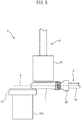
- FIG. 5 is a schematic partial side view of the preform coating device 5 at the time of application of the coating solution.
- the preform coating device 5 further comprises a rotary retention part 9 which retains the preform 1 in the horizontal direction and which rotates the preform 1 about the axis A of the preform 1.
- the rotary retention part 9 includes a chuck 91 for retaining the opening 1a of the preform 1, and a rotary shaft 92 connected to the chuck 91.
- the rotary retention part 9 retains the preform 1 in the horizontal direction by retaining the opening 1a of the preform 1 with the chuck 91.
- the preform 1 is cantilevered by the rotary retention part 9.
- the chuck 91 is, for example, a vacuum chuck that suctions the preform 1 with air, or a mechanical chuck that mechanically retains the preform 1. Note that though the chuck 91 in the present embodiment retains the interior of the opening 1a of the preform 1, the chuck 91 may retain the exterior of the opening 1a of the preform 1.
- the rotary shaft 92 is driven by a motor (not illustrated), and rotates together with the chuck 91.
- the axis of the rotary shaft 92 is co-axial with the axis A of the preform 1.
- the preform 1 can be rotated about the axis A.
- the rotary retention part 9 is connected to the belt 82.
- the conveyance part 8 can convey the preform 1 by moving the rotary retention part 9.
- the dispenser 6 is arranged above the cylindrical body 1b.
- the dispenser 6 houses the coating solution, and discharges the coating solution toward the preform 1.
- the coating solution is supplied to the dispenser 6 by a pump or the like.
- the dispenser 6 has a nozzle 61 for discharging the coating solution toward the cylindrical body 1b of the preform 1.
- a slot is formed in the tip of the nozzle 61.
- the dispenser 6 discharges the coating solution in a planar-like shape from the slot toward the preform 1.
- the width of the slot (the length in the axial direction of the preform 1) can be adjusted, and is, for example, 15 mm to 40 mm.
- the vertical width of the slot (the length in the direction orthogonal to the axial direction of the preform 1) can be adjusted, and is, for example, 0.1 mm to 1.0 mm.
- the dispenser 6 can move in the vertical direction. Thus, the distance between the slot of the nozzle 61 and the cylindrical body 1b of the preform 1 can be adjusted.
- the coating solution is discharged from above the preform 1 in the present embodiment, the coating solution may be discharged in other directions, for example, from below the preform 1.
- the dispenser 6 is configured so that the distance between the slot of the nozzle 61 and the cylindrical body 1b of the preform 1 can be adjusted.
- the conveyance part 8 does not move the rotary retention part 9 while the dispenser 6 discharges coating solution.
- the rotary retention part 9 rotates the preform 1 while the dispenser 6 discharges coating solution.
- the dispenser 6 continues to discharge coating solution while the preform 1 makes substantially one rotation.
- the discharged coating solution is wound up by the outer peripheral surface of the cylindrical body 1b of the preform 1.
- coating solution is applied to the entirety of the outer peripheral surface of the cylindrical body 1b of the preform 1.
- the thickness of the coating solution is prevented from gradually increasing toward the bottom 1c of the preform 1 due to gravity.
- the preform 1 is cantilevered by the rotary retention part 9, the outer peripheral surface of the preform 1 on the bottom 1c side tends to move away from the axis A of the preform 1 by the rotation of the preform 1. In other words, the rotation of the preform 1 causes eccentricity of the preform 1. As a result, the thickness of the coating solution applied to the preform 1 may not be uniform.
- the preform coating device 5 further comprises a preform support part 10.
- the preform support part 10 is supported by a supporting column 21c.
- the preform support part 10 rotatably supports the preform 1 at least while the dispenser 6 discharges the coating solution.
- the preform support part 10 supports the end of the cylindrical body 1b of the preform 1 on the bottom 1c side so as not to contact the applied coating solution.
- At least a portion of the preform support part 10 which contacts the preform 1 is made of a resin, and is preferably made of polyoxymethylene (POM).
- POM polyoxymethylene
- the preform 1 is conveyed to the location of the dryer 7 by the conveyance part 8.
- the conveyance part 8 conveys the preform 1 in a horizontally retained state.
- the dryer 7 is arranged spaced apart from the dispenser 6 along the conveyance path of the conveyance part 8, on the downstream side of the dispenser 6.
- the dryer 7 emits infrared light toward the coating solution applied to the preform 1.
- the coating solution applied to the preform 1 is dried by molecular vibration caused by irradiation with the infrared light.
- the dryer 7 is, for example, a carbon heater or a far-infrared light heater.
- the dryer 7 can extend, for example, along the conveyance path of the conveyance part 8.
- the preform coating device 5 can include a fixture 71 for securing the dryer 7.
- the rotary retention part 9 rotates the preform 1 while the dryer 7 dries the coating solution. As a result, the coating solution applied to the preform 1 can be uniformly dried.
- FIG. 6 is a schematic cross-sectional view taken along line VI-VI of FIG. 4 .
- the preform coating device 5 further comprises a reflector 72.
- the reflector 72 is arranged in a position facing the dyer 7 across the preform 1.
- the reflector 72 can, for example, extend along the conveyance path of the conveyance part 8.
- the reflector 72 is configured so as to redirect the infrared light emitted from the dryer 7 toward the preform 1.
- the surface of the reflector 72 facing the dryer 7 can have, for example, a substantially arc-shaped or substantially U-shaped cross-section.
- the reflector 72 may be, for example, a metal member (for example, a stainless steel or other metal plate) having a mirror-finished surface facing the dryer 7.
- the preform coating device 5 further comprises a first blower mechanism 31 for blowing gas on the preform 1 during drying by the dryer 7, a second blower mechanism 32 for blowing gas onto the surface of the dryer 7, and a third blower mechanism 33 for blowing gas on the preform 1 downstream from the dryer 7.
- the first blower mechanism 31 blows gas on the preform 1 for reducing temperature increases of the preform 1, at a position where the preform 1 is irradiated with infrared light by the dryer 7.
- the first blower mechanism 31 is configured so as to blow gas from an obliquely upward direction, at substantially the center of the dryer 7 on the conveyance path of the conveyance part 8.
- the first blower mechanism 31 may be configured so as to blow gas from another direction, at another location.
- the first blower mechanism 31 has a pipe 31a for blowing gas.
- the pipe 31a can be connected to, for example, an unillustrated blower or compressor.
- the first blower mechanism 31 blows gas on the preform 1 so as to maintain the temperature of the preform 1 at or below a predetermined temperature.
- the first blower mechanism 31 may blow, for example, room temperature gas (e.g., air or another gas) toward the preform 1.
- the room temperature air can be air which has not been intentionally heated or cooled by supplement equipment (e.g. air around a blower or compressor).
- the first blower mechanism 31 may, for example, blow gas which has been heated within a range where temperature increases of the preform 1 can be reduced, or may blow cooled gas, if necessary.
- the preform coating device 5 may include a thermometer (not illustrated) capable of measuring the temperature of at least one of the surface of the preform 1, the surface of the dryer 7, or the periphery of the preform 1 and the dryer 7.
- the first blower mechanism 31 has a flow rate adjustment mechanism 31b for adjusting the flow rate.
- the flow rate adjustment mechanism 31b can have, for example, a flow rate meter and/or a valve.
- the flow rate is too low, there is a risk that temperature increases of the preform 1 cannot be sufficiently reduced.
- the flow rate is too high, there is a risk of rippling of the coating solution applied to the preform 1, whereby there is a risk that the thickness of the coating solution may vary. In this case, there is a risk that the coating solution in portions where the thickness is large may not sufficiently dry.
- the flow rate of the first blower mechanism 31 can be, for example, 100 km 3 /min. It should be noted that this value is merely exemplary.
- the second blower mechanism 32 blows gas on the surface of the dryer 7 for reducing temperature increases of the surface of the dryer 7.
- the second blower mechanism 32 is configured so as to blow gas on the surface of the dryer 7 from the upstream side of the conveyance path of the conveyance part 8.
- the second blower mechanism 32 may be configured to as to blow gas onto the surface of the dryer 7 from the downstream side or from another location.
- the second blower mechanism 32 has a pipe 32a for blowing gas.
- the pipe 32a can be connected to, for example, an unillustrated blower or compressor.
- the second blower mechanism 32 can prevent the transmission of excess heat to the preform 1 by reducing temperature increases of the surface of the dryer 7.
- the second blower mechanism 32 may, for example, blow room temperature gas toward the surface of the dryer 7.
- the second blower mechanism 32 may, for example, blow gas which has been heated within a range where temperature increases of the surface of the dryer 7 can be reduced, or can blow cooled gas, if necessary.
- the second blower mechanism 32 has a flow rate adjustment mechanism 32b for adjusting the flow rate.
- the flow rate adjustment mechanism 32b can have, for example, a flow rate meter and/or a valve.
- the flow rate of the second blower mechanism 32 may be, for example, greater than the flow rate of the first blower mechanism 31, and can be, for example, 500 km 3 /min. It should be noted that this value is merely exemplary.
- the third blower mechanism 33 is arranged spaced apart from the dryer 7 along the conveyance path of the conveyance part 8, on the downstream side of the dryer 7.
- the third blower mechanism 33 blows gas toward the preform 1 irradiated with the infrared light.
- the third blower mechanism 33 has a pipe 33a for blowing gas.
- the pipe 33a can be connected to, for example, an unillustrated blower or compressor.
- the temperature of the preform 1 irradiated with the infrared light does not drop to room temperature for some time.
- the coating solution can be dried by the remaining heat.
- the third blower mechanism 33 may reduce the time for irradiation of the preform 1 with the infrared light by the dryer 7.
- the third blower mechanism 33 may blow, for example, room temperature gas toward the preform 1.
- the third blower mechanism 33 may, for example, blow heated gas or may blow cooled gas, if necessary.
- the third blower mechanism 33 has a flow rate adjustment mechanism 33b for adjusting the flow rate.
- the flow rate adjustment mechanism 33b can have, for example, a flow rate meter and/or a valve.
- the flow rate is excessively low, there is a risk that several minutes will be necessary for the coating solution applied to the preform 1 to dry.
- the flow rate is excessively high, there is a risk of rippling of the coating solution applied to the preform 1, whereby there is a risk that the thickness of the coating solution may vary. In this case, there is a risk that the coating solution in portions where the thickness is large may not sufficiently dry.
- the flow rate of the third blower mechanism 33 can be, for example, 100 km 3 /min. It should be noted that this value is merely exemplary.
- the conveyance part 8 conveys the preform 1 to the downstream of the third blower mechanism 33. Thereafter, the rotary retention part 9 releases the preform 1, and the preform 1 is removed from the preform coating device 5.
- the preform coating device 5 formation of a barrier coating on the outer peripheral surface of the preform 1 can be automated.
- the coating solution used in the present embodiment is, for example, a barrier coating solution having a gas barrier function such as a polyvinyl alcohol (PVA) solution.
- the coating solution may be a solution of a barrier resin such as a water-soluble polyamide, water-soluble polyester, polyvinylidene chloride (PVDC), polyacrylonitrile, ethylene-vinyl alcohol copolymer resin (EVOH), or polyglycolic acid.
- the coating solution may be obtained by adding an inorganic material to any of the solutions described above.
- the viscosity of the barrier coating solution is, for example, 25 mPa ⁇ s or more and 10000 mPa- s or less.
- a protective coating solution for protecting the barrier coating solution may be further applied on the barrier coating solution.
- the protective coating solution is, for example, a water-insoluble coating agent such as a polyolefin dispersion solution, various modified polyolefin dispersion solutions, or polyvinyl butyral (PVB).
- the viscosity of the protective coating solution may be, for example, 0.5 mPa ⁇ s or more and 100 mPa ⁇ s or less.
- the protective coating solution can be applied to the preform 1 using the preform coating device 5.
- the coating solution applied to the preform 1 is dried by molecular vibration caused by the irradiation of infrared light.
- the temperature of the preform 1 is increased due to the irradiation of infrared light.
- softening and/or whitening of the preform 1 may occur.
- gas for reducing temperature increases of the preform 1 is blown toward the preform 1 by the first blower mechanism 31 in the position in which the preform 1 is irradiated with the infrared light by the dryer 7.
- excessive temperature increases of the preform 1 can be prevented. Therefore, the quality of the preform 1 can be increased.
- the preform coating device 5 further comprises a flow rate adjustment mechanism 31b for adjusting the flow rate of the first blower mechanism 31.
- the flow rate can be optimized in order to reduce temperature increases of the preform 1.
- the preform coating device 5 further comprises a reflector 72 arranged in a position opposite the dryer 7 across the preform 1.
- a reflector 72 arranged in a position opposite the dryer 7 across the preform 1.
- the first blower mechanism 31 blows room temperature gas.
- a simple blower mechanism can be adopted, whereby increases in the cost of the device can be avoided.
- the preform coating device 5 further comprises a second blower mechanism 32 for blowing gas on the surface of the dryer 7 for reducing temperature increases of the surface of the dryer 7. Thus, the transmission of excess heat from the surface of the dryer 7 to the preform 1 can be prevented.
- the preform coating device 5 further comprises a flow rate adjustment mechanism 32b for adjusting the flow rate of the second blower mechanism 32.
- the flow rate can be optimized in order to reduce temperature increases of the surface of the dryer 7.
- the second blower mechanism 32 blows room temperature gas.
- a simple blower mechanism can be adopted, whereby increases in the cost of the device can be avoided.
- the third blower mechanism 33 for blowing gas toward the preform 1 is provided on the downstream of the dryer 7.
- the coating solution can be dried by blowing at the downstream of the dryer 7.
- the time for drying the coating solution by the dryer 7 can be reduced, i.e. the time for irradiating the preform 1 with infrared light by the dryer 7 can be reduced, whereby excessive temperature increases of the preform 1 can be prevented. Therefore, the quality of the preform 1 can be improved.
- the preform coating device 5 may further comprise a flow rate adjustment mechanism 33b for adjusting the flow rate of the third blower mechanism 33.
- the flow rate can be optimized in order to dry the coating solution.
- the third blower mechanism 33 blows room temperature gas.
- a simple blower mechanism can be adopted, whereby increases in the cost of the device can be avoided.
- the preform coating device 5 may comprise a plurality of rotary retention parts 9.
- the plurality of rotary retention parts 9 can be arranged along the belt 82 of the conveyance part 8 spaced apart at predetermined intervals, and the conveyance part 8 can continuously convey a plurality of preforms 1. Due to this configuration, a plurality of preforms 1 can be continuously coated, whereby preform 1 productivity can be improved.
- the preform coating device 5 may comprise a plurality of dispensers 6.
- the dispenser 6 may have a plurality of nozzles 61.
- the preform coating device 5 need not comprise a reflector 72.
- the preform coating device 5 may comprise another dryer arranged in a position facing the dryer 7 (arranged below the preform 1).
- the additional dryer may be provided with a second blower mechanism.
- the rotary retention part 9 may retain the preform 1 in a direction other than the horizontal direction.
- Coating Solution PVA solution Amount of applied Coating Solution: 230 mg
- Dryer Heaters arranged above and below the preform
- Flow Rate of First Blower Mechanism 100 km 3 /min (note that when the flow rates of the first blower mechanism and the third blower mechanism were 160 km 3 /min or more, rippling of the coating solution occurred, causing drying defects.)
- Flow Rate of Third Blower Mechanism 100 km 3 /min
- Table 1 The drying times in Table 1 represent the time necessary for the coating solution to dry.
- the drying time by the third blower mechanism (lower value) is also shown as the drying time, in addition to the time of drying by the heater and/or the first blower mechanism (upper value).
- the coating solution was dried by only the heater.
- the heater temperature was 550 °C. This preform had the greatest softening. Whitening occurred in this preform.
- Example 1 the coating solution was dried by the heater and the first blower mechanism.
- the heater temperature was 550 °C. Though this preform had significant softening, whitening did not occur.
- Comparative Example and Example 1 it can be understood use of the first blower mechanism resulted in an increase in the quality of the preform.
- Example 2 the coating solution was dried by the heater, the first blower mechanism, and the third blower mechanism.
- the heater temperature was 550 °C.
- Example 3 the coating solution was dried by the heater, the first blower mechanism, and the third blower mechanism.
- the heater temperature was 300 °C. A slight amount of softening occurred in the preform.
- Example 4 the coating solution was dried by the heater, the first blower mechanism, and the third blower mechanism.
- the heater temperature was 100 °C. No softening occurred in the preform.
- Example 5 the coating solution was dried by the heater and the third blower mechanism.
- the heater temperature was 100 °C. No softening occurred in the preform.
- Coating Solution PVA solution Amount of applied Coating Solution: 230 mg
- Dryer Heaters arranged above and below the preform Dryer Temperature: 300 °C
- Reflector Mirror-finished stainless steel plate
Landscapes
- Engineering & Computer Science (AREA)
- Mechanical Engineering (AREA)
- Manufacturing & Machinery (AREA)
- Physics & Mathematics (AREA)
- Geometry (AREA)
- Life Sciences & Earth Sciences (AREA)
- Wood Science & Technology (AREA)
- Blow-Moulding Or Thermoforming Of Plastics Or The Like (AREA)
- Coating Apparatus (AREA)
- Processing And Handling Of Plastics And Other Materials For Molding In General (AREA)
Applications Claiming Priority (2)
| Application Number | Priority Date | Filing Date | Title |
|---|---|---|---|
| JP2017248463 | 2017-12-25 | ||
| PCT/JP2018/047663 WO2019131678A1 (ja) | 2017-12-25 | 2018-12-25 | プリフォームコーティング装置 |
Publications (2)
| Publication Number | Publication Date |
|---|---|
| EP3733301A1 true EP3733301A1 (de) | 2020-11-04 |
| EP3733301A4 EP3733301A4 (de) | 2021-09-01 |
Family
ID=67067392
Family Applications (1)
| Application Number | Title | Priority Date | Filing Date |
|---|---|---|---|
| EP18895710.4A Withdrawn EP3733301A4 (de) | 2017-12-25 | 2018-12-25 | Vorformbeschichtungsvorrichtung |
Country Status (6)
| Country | Link |
|---|---|
| US (1) | US11453027B2 (de) |
| EP (1) | EP3733301A4 (de) |
| JP (1) | JP7016887B2 (de) |
| CN (1) | CN111372691B (de) |
| AU (1) | AU2018395352B2 (de) |
| WO (1) | WO2019131678A1 (de) |
Family Cites Families (25)
| Publication number | Priority date | Publication date | Assignee | Title |
|---|---|---|---|---|
| US4054630A (en) * | 1976-01-22 | 1977-10-18 | American Can Company | Hot pin parison injection molding technique |
| JPS5412175A (en) * | 1977-06-29 | 1979-01-29 | Toshiba Electric Equip | Device for radiating radiation ray |
| US4192843A (en) * | 1977-12-12 | 1980-03-11 | Rheem Manufacturing Company | Method for blow molding of thermoplastic articles |
| FR2416784A1 (fr) * | 1978-02-13 | 1979-09-07 | Rhone Poulenc Ind | Procede de fabrication de corps creux biorientes |
| JPS59216654A (ja) * | 1983-05-24 | 1984-12-06 | Toyo Seikan Kaisha Ltd | パリソンに塗膜を被覆する装置 |
| JPH0398975U (de) * | 1990-01-30 | 1991-10-15 | ||
| JPH0534068A (ja) * | 1991-07-26 | 1993-02-09 | Setsuo Tate | 乾燥装置 |
| US20050033562A1 (en) * | 2001-02-06 | 2005-02-10 | Takeshi Narushima | Method and device for design of preform |
| BRPI0513163A (pt) * | 2004-07-09 | 2008-04-29 | Advanced Plastics Technologies | aparelho e processo de revestimento para formação de artigos revestidos |
| JP4831353B2 (ja) * | 2007-02-26 | 2011-12-07 | 東洋製罐株式会社 | 空調付きブロー成形機 |
| KR101350703B1 (ko) | 2007-02-26 | 2014-01-10 | 도요세이칸 그룹 홀딩스 가부시키가이샤 | 공조 장착 블로우 성형기 |
| US20110034992A1 (en) * | 2009-08-04 | 2011-02-10 | Papp John E | Stent and Method of Coating Same |
| EP2532600B1 (de) | 2011-06-06 | 2020-01-22 | Kuraray Europe GmbH | Kunststoffbehälter mit gasbarrierebeschichtung und optionaler wasserabweisender innenbeschichtung |
| JP5912762B2 (ja) * | 2012-03-29 | 2016-04-27 | 日東電工株式会社 | ダイコーター及び塗布膜の製造方法 |
| JP6037879B2 (ja) * | 2013-02-13 | 2016-12-07 | サントリーホールディングス株式会社 | ガスバリアコーティングを有するプラスチックボトル用プリフォーム |
| CN104149322A (zh) * | 2013-05-15 | 2014-11-19 | 阿博姆公司 | 用于红外加热塑料预成型件的设备 |
| CN103331904B (zh) * | 2013-06-21 | 2015-09-02 | 杭州中亚机械股份有限公司 | 一种旋转吹瓶机的瓶胚冷却装置 |
| JP2015199012A (ja) | 2014-04-04 | 2015-11-12 | サントリーホールディングス株式会社 | プリフォームコーティング装置、プリフォームの製造方法及びプラスチックボトルの製造方法 |
| DE102014006275A1 (de) * | 2014-05-02 | 2015-11-19 | Khs Corpoplast Gmbh | Verfahren und Vorrichtung zum Temperieren von Vorformlingen |
| CN205048894U (zh) * | 2015-09-10 | 2016-02-24 | 上海热丽科技集团有限公司 | 远红外多功能干燥系统 |
| JP6537429B2 (ja) | 2015-09-30 | 2019-07-03 | サントリーホールディングス株式会社 | プリフォームコーティング装置 |
| JP6537426B2 (ja) | 2015-09-30 | 2019-07-03 | サントリーホールディングス株式会社 | プリフォームコーティング装置及びプリフォームコーティング方法 |
| ES2884873T3 (es) * | 2015-09-30 | 2021-12-13 | Suntory Holdings Ltd | Dispositivo de revestimiento de preformas y método de revestimiento de preformas |
| CN205316846U (zh) * | 2015-11-02 | 2016-06-15 | 浙江绿健胶囊有限公司 | 一种恒温红外线胶囊干燥装置 |
| CN206626912U (zh) * | 2017-04-05 | 2017-11-10 | 何嵬 | 一种密封件的夹紧旋转烘干装置 |
-
2018
- 2018-12-25 EP EP18895710.4A patent/EP3733301A4/de not_active Withdrawn
- 2018-12-25 JP JP2019562052A patent/JP7016887B2/ja active Active
- 2018-12-25 AU AU2018395352A patent/AU2018395352B2/en not_active Ceased
- 2018-12-25 CN CN201880075397.7A patent/CN111372691B/zh not_active Expired - Fee Related
- 2018-12-25 US US16/957,194 patent/US11453027B2/en active Active
- 2018-12-25 WO PCT/JP2018/047663 patent/WO2019131678A1/ja not_active Ceased
Also Published As
| Publication number | Publication date |
|---|---|
| WO2019131678A1 (ja) | 2019-07-04 |
| JPWO2019131678A1 (ja) | 2020-12-24 |
| CN111372691A (zh) | 2020-07-03 |
| JP7016887B2 (ja) | 2022-02-07 |
| US20200331022A1 (en) | 2020-10-22 |
| AU2018395352B2 (en) | 2021-10-07 |
| EP3733301A4 (de) | 2021-09-01 |
| CN111372691B (zh) | 2022-04-19 |
| US11453027B2 (en) | 2022-09-27 |
| AU2018395352A1 (en) | 2020-07-09 |
Similar Documents
| Publication | Publication Date | Title |
|---|---|---|
| JP6537429B2 (ja) | プリフォームコーティング装置 | |
| CN108025330B (zh) | 预塑件涂敷装置及预塑件涂敷方法 | |
| JP6537426B2 (ja) | プリフォームコーティング装置及びプリフォームコーティング方法 | |
| US11260417B2 (en) | Preform coating device | |
| US11453027B2 (en) | Preform coating device | |
| EP3733304A1 (de) | Vorformbeschichtungsvorrichtung | |
| US11511310B2 (en) | Preform coating device |
Legal Events
| Date | Code | Title | Description |
|---|---|---|---|
| STAA | Information on the status of an ep patent application or granted ep patent |
Free format text: STATUS: THE INTERNATIONAL PUBLICATION HAS BEEN MADE |
|
| PUAI | Public reference made under article 153(3) epc to a published international application that has entered the european phase |
Free format text: ORIGINAL CODE: 0009012 |
|
| STAA | Information on the status of an ep patent application or granted ep patent |
Free format text: STATUS: REQUEST FOR EXAMINATION WAS MADE |
|
| 17P | Request for examination filed |
Effective date: 20200618 |
|
| AK | Designated contracting states |
Kind code of ref document: A1 Designated state(s): AL AT BE BG CH CY CZ DE DK EE ES FI FR GB GR HR HU IE IS IT LI LT LU LV MC MK MT NL NO PL PT RO RS SE SI SK SM TR |
|
| AX | Request for extension of the european patent |
Extension state: BA ME |
|
| DAV | Request for validation of the european patent (deleted) | ||
| DAX | Request for extension of the european patent (deleted) | ||
| A4 | Supplementary search report drawn up and despatched |
Effective date: 20210802 |
|
| RIC1 | Information provided on ipc code assigned before grant |
Ipc: B05C 5/00 20060101AFI20210727BHEP Ipc: B05C 9/14 20060101ALI20210727BHEP Ipc: B05C 13/02 20060101ALI20210727BHEP Ipc: B29C 49/22 20060101ALI20210727BHEP Ipc: B29B 11/14 20060101ALI20210727BHEP Ipc: B05D 1/00 20060101ALN20210727BHEP Ipc: B05D 1/26 20060101ALN20210727BHEP Ipc: B29B 11/08 20060101ALN20210727BHEP Ipc: B29C 49/02 20060101ALN20210727BHEP Ipc: B29L 31/00 20060101ALN20210727BHEP Ipc: B29C 49/12 20060101ALN20210727BHEP Ipc: B29K 23/00 20060101ALN20210727BHEP Ipc: B29K 27/00 20060101ALN20210727BHEP Ipc: B29K 31/00 20060101ALN20210727BHEP Ipc: B29L 9/00 20060101ALN20210727BHEP |
|
| REG | Reference to a national code |
Ref country code: DE Ref legal event code: R079 Free format text: PREVIOUS MAIN CLASS: B05C0005000000 Ipc: B29B0011140000 |
|
| GRAP | Despatch of communication of intention to grant a patent |
Free format text: ORIGINAL CODE: EPIDOSNIGR1 |
|
| STAA | Information on the status of an ep patent application or granted ep patent |
Free format text: STATUS: GRANT OF PATENT IS INTENDED |
|
| RIC1 | Information provided on ipc code assigned before grant |
Ipc: B05D 1/16 20060101ALN20230307BHEP Ipc: B05C 9/14 20060101ALN20230307BHEP Ipc: B29C 49/22 20060101ALN20230307BHEP Ipc: B29L 9/00 20060101ALN20230307BHEP Ipc: B29K 31/00 20060101ALN20230307BHEP Ipc: B29K 27/00 20060101ALN20230307BHEP Ipc: B29K 23/00 20060101ALN20230307BHEP Ipc: B29C 49/12 20060101ALN20230307BHEP Ipc: B29L 31/00 20060101ALN20230307BHEP Ipc: B29C 49/02 20060101ALN20230307BHEP Ipc: B29B 11/08 20060101ALN20230307BHEP Ipc: B05D 1/26 20060101ALN20230307BHEP Ipc: B05D 1/00 20060101ALN20230307BHEP Ipc: B05D 7/02 20060101ALI20230307BHEP Ipc: B05D 3/04 20060101ALI20230307BHEP Ipc: B05D 3/02 20060101ALI20230307BHEP Ipc: B05C 13/02 20060101ALI20230307BHEP Ipc: B05C 5/00 20060101ALI20230307BHEP Ipc: B29B 11/14 20060101AFI20230307BHEP |
|
| RIC1 | Information provided on ipc code assigned before grant |
Ipc: B05D 1/16 20060101ALN20230316BHEP Ipc: B05C 9/14 20060101ALN20230316BHEP Ipc: B29C 49/22 20060101ALN20230316BHEP Ipc: B29L 9/00 20060101ALN20230316BHEP Ipc: B29K 31/00 20060101ALN20230316BHEP Ipc: B29K 27/00 20060101ALN20230316BHEP Ipc: B29K 23/00 20060101ALN20230316BHEP Ipc: B29C 49/12 20060101ALN20230316BHEP Ipc: B29L 31/00 20060101ALN20230316BHEP Ipc: B29C 49/02 20060101ALN20230316BHEP Ipc: B29B 11/08 20060101ALN20230316BHEP Ipc: B05D 1/26 20060101ALN20230316BHEP Ipc: B05D 1/00 20060101ALN20230316BHEP Ipc: B05D 7/02 20060101ALI20230316BHEP Ipc: B05D 3/04 20060101ALI20230316BHEP Ipc: B05D 3/02 20060101ALI20230316BHEP Ipc: B05C 13/02 20060101ALI20230316BHEP Ipc: B05C 5/00 20060101ALI20230316BHEP Ipc: B29B 11/14 20060101AFI20230316BHEP |
|
| INTG | Intention to grant announced |
Effective date: 20230404 |
|
| STAA | Information on the status of an ep patent application or granted ep patent |
Free format text: STATUS: THE APPLICATION IS DEEMED TO BE WITHDRAWN |
|
| 18D | Application deemed to be withdrawn |
Effective date: 20230815 |