EP3733302A1 - Vorformbeschichtungsvorrichtung - Google Patents
Vorformbeschichtungsvorrichtung Download PDFInfo
- Publication number
- EP3733302A1 EP3733302A1 EP18896279.9A EP18896279A EP3733302A1 EP 3733302 A1 EP3733302 A1 EP 3733302A1 EP 18896279 A EP18896279 A EP 18896279A EP 3733302 A1 EP3733302 A1 EP 3733302A1
- Authority
- EP
- European Patent Office
- Prior art keywords
- preform
- dispenser
- opening
- coating solution
- coating
- Prior art date
- Legal status (The legal status is an assumption and is not a legal conclusion. Google has not performed a legal analysis and makes no representation as to the accuracy of the status listed.)
- Withdrawn
Links
- 238000000576 coating method Methods 0.000 title claims abstract description 129
- 239000011248 coating agent Substances 0.000 title claims abstract description 128
- 238000007599 discharging Methods 0.000 claims abstract description 6
- 230000014759 maintenance of location Effects 0.000 claims description 43
- 229920003023 plastic Polymers 0.000 claims description 29
- 239000004033 plastic Substances 0.000 claims description 29
- 230000002093 peripheral effect Effects 0.000 claims description 22
- 235000014171 carbonated beverage Nutrition 0.000 claims description 6
- 239000007788 liquid Substances 0.000 abstract 3
- 239000000243 solution Substances 0.000 description 70
- 230000004888 barrier function Effects 0.000 description 16
- -1 polyethylene terephthalate Polymers 0.000 description 6
- 229920000139 polyethylene terephthalate Polymers 0.000 description 6
- 239000005020 polyethylene terephthalate Substances 0.000 description 6
- 238000001035 drying Methods 0.000 description 5
- 239000007789 gas Substances 0.000 description 5
- 238000000465 moulding Methods 0.000 description 5
- 229920005989 resin Polymers 0.000 description 5
- 239000011347 resin Substances 0.000 description 5
- CURLTUGMZLYLDI-UHFFFAOYSA-N Carbon dioxide Chemical compound O=C=O CURLTUGMZLYLDI-UHFFFAOYSA-N 0.000 description 4
- 238000000071 blow moulding Methods 0.000 description 4
- 230000000694 effects Effects 0.000 description 4
- 239000011253 protective coating Substances 0.000 description 4
- 229930040373 Paraformaldehyde Natural products 0.000 description 3
- 239000011247 coating layer Substances 0.000 description 3
- 238000004891 communication Methods 0.000 description 3
- 239000012530 fluid Substances 0.000 description 3
- 229920006324 polyoxymethylene Polymers 0.000 description 3
- 230000000717 retained effect Effects 0.000 description 3
- OKTJSMMVPCPJKN-UHFFFAOYSA-N Carbon Chemical compound [C] OKTJSMMVPCPJKN-UHFFFAOYSA-N 0.000 description 2
- 229920000219 Ethylene vinyl alcohol Polymers 0.000 description 2
- 239000004698 Polyethylene Substances 0.000 description 2
- 239000004743 Polypropylene Substances 0.000 description 2
- 239000004372 Polyvinyl alcohol Substances 0.000 description 2
- QVGXLLKOCUKJST-UHFFFAOYSA-N atomic oxygen Chemical compound [O] QVGXLLKOCUKJST-UHFFFAOYSA-N 0.000 description 2
- 235000013361 beverage Nutrition 0.000 description 2
- 229910052799 carbon Inorganic materials 0.000 description 2
- 229910002092 carbon dioxide Inorganic materials 0.000 description 2
- 239000001569 carbon dioxide Substances 0.000 description 2
- 239000006185 dispersion Substances 0.000 description 2
- 230000005484 gravity Effects 0.000 description 2
- 238000000034 method Methods 0.000 description 2
- 229910052760 oxygen Inorganic materials 0.000 description 2
- 239000001301 oxygen Substances 0.000 description 2
- 229920002037 poly(vinyl butyral) polymer Polymers 0.000 description 2
- 229920000573 polyethylene Polymers 0.000 description 2
- 229920000098 polyolefin Polymers 0.000 description 2
- 229920001155 polypropylene Polymers 0.000 description 2
- 229920002451 polyvinyl alcohol Polymers 0.000 description 2
- 238000012360 testing method Methods 0.000 description 2
- 239000004952 Polyamide Substances 0.000 description 1
- 229920000954 Polyglycolide Polymers 0.000 description 1
- 230000005540 biological transmission Effects 0.000 description 1
- 230000015572 biosynthetic process Effects 0.000 description 1
- 238000000748 compression moulding Methods 0.000 description 1
- 238000001816 cooling Methods 0.000 description 1
- 238000011161 development Methods 0.000 description 1
- 239000004715 ethylene vinyl alcohol Substances 0.000 description 1
- 238000010438 heat treatment Methods 0.000 description 1
- 238000001746 injection moulding Methods 0.000 description 1
- 229910010272 inorganic material Inorganic materials 0.000 description 1
- 239000011147 inorganic material Substances 0.000 description 1
- 238000009434 installation Methods 0.000 description 1
- 238000004519 manufacturing process Methods 0.000 description 1
- 238000012986 modification Methods 0.000 description 1
- 230000004048 modification Effects 0.000 description 1
- 230000035515 penetration Effects 0.000 description 1
- 229920002239 polyacrylonitrile Polymers 0.000 description 1
- 229920002647 polyamide Polymers 0.000 description 1
- 229920000728 polyester Polymers 0.000 description 1
- 239000004633 polyglycolic acid Substances 0.000 description 1
- 239000005033 polyvinylidene chloride Substances 0.000 description 1
- 238000011144 upstream manufacturing Methods 0.000 description 1
Images


Classifications
-
- B—PERFORMING OPERATIONS; TRANSPORTING
- B05—SPRAYING OR ATOMISING IN GENERAL; APPLYING FLUENT MATERIALS TO SURFACES, IN GENERAL
- B05C—APPARATUS FOR APPLYING FLUENT MATERIALS TO SURFACES, IN GENERAL
- B05C5/00—Apparatus in which liquid or other fluent material is projected, poured or allowed to flow on to the surface of the work
- B05C5/02—Apparatus in which liquid or other fluent material is projected, poured or allowed to flow on to the surface of the work the liquid or other fluent material being discharged through an outlet orifice by pressure, e.g. from an outlet device in contact or almost in contact, with the work
-
- B—PERFORMING OPERATIONS; TRANSPORTING
- B29—WORKING OF PLASTICS; WORKING OF SUBSTANCES IN A PLASTIC STATE IN GENERAL
- B29B—PREPARATION OR PRETREATMENT OF THE MATERIAL TO BE SHAPED; MAKING GRANULES OR PREFORMS; RECOVERY OF PLASTICS OR OTHER CONSTITUENTS OF WASTE MATERIAL CONTAINING PLASTICS
- B29B11/00—Making preforms
- B29B11/14—Making preforms characterised by structure or composition
-
- B—PERFORMING OPERATIONS; TRANSPORTING
- B05—SPRAYING OR ATOMISING IN GENERAL; APPLYING FLUENT MATERIALS TO SURFACES, IN GENERAL
- B05B—SPRAYING APPARATUS; ATOMISING APPARATUS; NOZZLES
- B05B15/00—Details of spraying plant or spraying apparatus not otherwise provided for; Accessories
- B05B15/60—Arrangements for mounting, supporting or holding spraying apparatus
- B05B15/65—Mounting arrangements for fluid connection of the spraying apparatus or its outlets to flow conduits
- B05B15/656—Mounting arrangements for fluid connection of the spraying apparatus or its outlets to flow conduits whereby the flow conduit length is changeable
-
- B—PERFORMING OPERATIONS; TRANSPORTING
- B05—SPRAYING OR ATOMISING IN GENERAL; APPLYING FLUENT MATERIALS TO SURFACES, IN GENERAL
- B05C—APPARATUS FOR APPLYING FLUENT MATERIALS TO SURFACES, IN GENERAL
- B05C13/00—Means for manipulating or holding work, e.g. for separate articles
- B05C13/02—Means for manipulating or holding work, e.g. for separate articles for particular articles
- B05C13/025—Means for manipulating or holding work, e.g. for separate articles for particular articles relatively small cylindrical objects, e.g. cans, bottles
-
- B—PERFORMING OPERATIONS; TRANSPORTING
- B05—SPRAYING OR ATOMISING IN GENERAL; APPLYING FLUENT MATERIALS TO SURFACES, IN GENERAL
- B05C—APPARATUS FOR APPLYING FLUENT MATERIALS TO SURFACES, IN GENERAL
- B05C5/00—Apparatus in which liquid or other fluent material is projected, poured or allowed to flow on to the surface of the work
- B05C5/02—Apparatus in which liquid or other fluent material is projected, poured or allowed to flow on to the surface of the work the liquid or other fluent material being discharged through an outlet orifice by pressure, e.g. from an outlet device in contact or almost in contact, with the work
- B05C5/027—Coating heads with several outlets, e.g. aligned transversally to the moving direction of a web to be coated
- B05C5/0275—Coating heads with several outlets, e.g. aligned transversally to the moving direction of a web to be coated flow controlled, e.g. by a valve
- B05C5/0279—Coating heads with several outlets, e.g. aligned transversally to the moving direction of a web to be coated flow controlled, e.g. by a valve independently, e.g. individually, flow controlled
-
- B—PERFORMING OPERATIONS; TRANSPORTING
- B29—WORKING OF PLASTICS; WORKING OF SUBSTANCES IN A PLASTIC STATE IN GENERAL
- B29B—PREPARATION OR PRETREATMENT OF THE MATERIAL TO BE SHAPED; MAKING GRANULES OR PREFORMS; RECOVERY OF PLASTICS OR OTHER CONSTITUENTS OF WASTE MATERIAL CONTAINING PLASTICS
- B29B15/00—Pretreatment of the material to be shaped, not covered by groups B29B7/00 - B29B13/00
-
- B—PERFORMING OPERATIONS; TRANSPORTING
- B29—WORKING OF PLASTICS; WORKING OF SUBSTANCES IN A PLASTIC STATE IN GENERAL
- B29C—SHAPING OR JOINING OF PLASTICS; SHAPING OF MATERIAL IN A PLASTIC STATE, NOT OTHERWISE PROVIDED FOR; AFTER-TREATMENT OF THE SHAPED PRODUCTS, e.g. REPAIRING
- B29C49/00—Blow-moulding, i.e. blowing a preform or parison to a desired shape within a mould; Apparatus therefor
- B29C49/0005—Blow-moulding, i.e. blowing a preform or parison to a desired shape within a mould; Apparatus therefor characterised by the material
-
- B—PERFORMING OPERATIONS; TRANSPORTING
- B29—WORKING OF PLASTICS; WORKING OF SUBSTANCES IN A PLASTIC STATE IN GENERAL
- B29C—SHAPING OR JOINING OF PLASTICS; SHAPING OF MATERIAL IN A PLASTIC STATE, NOT OTHERWISE PROVIDED FOR; AFTER-TREATMENT OF THE SHAPED PRODUCTS, e.g. REPAIRING
- B29C49/00—Blow-moulding, i.e. blowing a preform or parison to a desired shape within a mould; Apparatus therefor
- B29C49/02—Combined blow-moulding and manufacture of the preform or the parison
-
- B—PERFORMING OPERATIONS; TRANSPORTING
- B29—WORKING OF PLASTICS; WORKING OF SUBSTANCES IN A PLASTIC STATE IN GENERAL
- B29C—SHAPING OR JOINING OF PLASTICS; SHAPING OF MATERIAL IN A PLASTIC STATE, NOT OTHERWISE PROVIDED FOR; AFTER-TREATMENT OF THE SHAPED PRODUCTS, e.g. REPAIRING
- B29C49/00—Blow-moulding, i.e. blowing a preform or parison to a desired shape within a mould; Apparatus therefor
- B29C49/071—Preforms or parisons characterised by their configuration, e.g. geometry, dimensions or physical properties
-
- B—PERFORMING OPERATIONS; TRANSPORTING
- B29—WORKING OF PLASTICS; WORKING OF SUBSTANCES IN A PLASTIC STATE IN GENERAL
- B29C—SHAPING OR JOINING OF PLASTICS; SHAPING OF MATERIAL IN A PLASTIC STATE, NOT OTHERWISE PROVIDED FOR; AFTER-TREATMENT OF THE SHAPED PRODUCTS, e.g. REPAIRING
- B29C49/00—Blow-moulding, i.e. blowing a preform or parison to a desired shape within a mould; Apparatus therefor
- B29C49/08—Biaxial stretching during blow-moulding
- B29C49/10—Biaxial stretching during blow-moulding using mechanical means for prestretching
- B29C49/12—Stretching rods
-
- B—PERFORMING OPERATIONS; TRANSPORTING
- B29—WORKING OF PLASTICS; WORKING OF SUBSTANCES IN A PLASTIC STATE IN GENERAL
- B29C—SHAPING OR JOINING OF PLASTICS; SHAPING OF MATERIAL IN A PLASTIC STATE, NOT OTHERWISE PROVIDED FOR; AFTER-TREATMENT OF THE SHAPED PRODUCTS, e.g. REPAIRING
- B29C49/00—Blow-moulding, i.e. blowing a preform or parison to a desired shape within a mould; Apparatus therefor
- B29C49/42—Component parts, details or accessories; Auxiliary operations
- B29C49/4273—Auxiliary operations after the blow-moulding operation not otherwise provided for
- B29C49/42828—Coating or painting the article
-
- B—PERFORMING OPERATIONS; TRANSPORTING
- B05—SPRAYING OR ATOMISING IN GENERAL; APPLYING FLUENT MATERIALS TO SURFACES, IN GENERAL
- B05B—SPRAYING APPARATUS; ATOMISING APPARATUS; NOZZLES
- B05B1/00—Nozzles, spray heads or other outlets, with or without auxiliary devices such as valves, heating means
- B05B1/02—Nozzles, spray heads or other outlets, with or without auxiliary devices such as valves, heating means designed to produce a jet, spray, or other discharge of particular shape or nature, e.g. in single drops, or having an outlet of particular shape
- B05B1/04—Nozzles, spray heads or other outlets, with or without auxiliary devices such as valves, heating means designed to produce a jet, spray, or other discharge of particular shape or nature, e.g. in single drops, or having an outlet of particular shape in flat form, e.g. fan-like, sheet-like
-
- B—PERFORMING OPERATIONS; TRANSPORTING
- B05—SPRAYING OR ATOMISING IN GENERAL; APPLYING FLUENT MATERIALS TO SURFACES, IN GENERAL
- B05B—SPRAYING APPARATUS; ATOMISING APPARATUS; NOZZLES
- B05B1/00—Nozzles, spray heads or other outlets, with or without auxiliary devices such as valves, heating means
- B05B1/14—Nozzles, spray heads or other outlets, with or without auxiliary devices such as valves, heating means with multiple outlet openings; with strainers in or outside the outlet opening
-
- B—PERFORMING OPERATIONS; TRANSPORTING
- B05—SPRAYING OR ATOMISING IN GENERAL; APPLYING FLUENT MATERIALS TO SURFACES, IN GENERAL
- B05C—APPARATUS FOR APPLYING FLUENT MATERIALS TO SURFACES, IN GENERAL
- B05C5/00—Apparatus in which liquid or other fluent material is projected, poured or allowed to flow on to the surface of the work
- B05C5/02—Apparatus in which liquid or other fluent material is projected, poured or allowed to flow on to the surface of the work the liquid or other fluent material being discharged through an outlet orifice by pressure, e.g. from an outlet device in contact or almost in contact, with the work
- B05C5/0254—Coating heads with slot-shaped outlet
-
- B—PERFORMING OPERATIONS; TRANSPORTING
- B29—WORKING OF PLASTICS; WORKING OF SUBSTANCES IN A PLASTIC STATE IN GENERAL
- B29B—PREPARATION OR PRETREATMENT OF THE MATERIAL TO BE SHAPED; MAKING GRANULES OR PREFORMS; RECOVERY OF PLASTICS OR OTHER CONSTITUENTS OF WASTE MATERIAL CONTAINING PLASTICS
- B29B11/00—Making preforms
- B29B11/06—Making preforms by moulding the material
- B29B11/08—Injection moulding
-
- B—PERFORMING OPERATIONS; TRANSPORTING
- B29—WORKING OF PLASTICS; WORKING OF SUBSTANCES IN A PLASTIC STATE IN GENERAL
- B29C—SHAPING OR JOINING OF PLASTICS; SHAPING OF MATERIAL IN A PLASTIC STATE, NOT OTHERWISE PROVIDED FOR; AFTER-TREATMENT OF THE SHAPED PRODUCTS, e.g. REPAIRING
- B29C2949/00—Indexing scheme relating to blow-moulding
- B29C2949/07—Preforms or parisons characterised by their configuration
- B29C2949/0715—Preforms or parisons characterised by their configuration the preform having one end closed
-
- B—PERFORMING OPERATIONS; TRANSPORTING
- B29—WORKING OF PLASTICS; WORKING OF SUBSTANCES IN A PLASTIC STATE IN GENERAL
- B29C—SHAPING OR JOINING OF PLASTICS; SHAPING OF MATERIAL IN A PLASTIC STATE, NOT OTHERWISE PROVIDED FOR; AFTER-TREATMENT OF THE SHAPED PRODUCTS, e.g. REPAIRING
- B29C2949/00—Indexing scheme relating to blow-moulding
- B29C2949/30—Preforms or parisons made of several components
- B29C2949/3016—Preforms or parisons made of several components at body portion
-
- B—PERFORMING OPERATIONS; TRANSPORTING
- B29—WORKING OF PLASTICS; WORKING OF SUBSTANCES IN A PLASTIC STATE IN GENERAL
- B29C—SHAPING OR JOINING OF PLASTICS; SHAPING OF MATERIAL IN A PLASTIC STATE, NOT OTHERWISE PROVIDED FOR; AFTER-TREATMENT OF THE SHAPED PRODUCTS, e.g. REPAIRING
- B29C2949/00—Indexing scheme relating to blow-moulding
- B29C2949/30—Preforms or parisons made of several components
- B29C2949/3032—Preforms or parisons made of several components having components being injected
-
- B—PERFORMING OPERATIONS; TRANSPORTING
- B29—WORKING OF PLASTICS; WORKING OF SUBSTANCES IN A PLASTIC STATE IN GENERAL
- B29C—SHAPING OR JOINING OF PLASTICS; SHAPING OF MATERIAL IN A PLASTIC STATE, NOT OTHERWISE PROVIDED FOR; AFTER-TREATMENT OF THE SHAPED PRODUCTS, e.g. REPAIRING
- B29C2949/00—Indexing scheme relating to blow-moulding
- B29C2949/30—Preforms or parisons made of several components
- B29C2949/3064—Preforms or parisons made of several components having at least one components being applied using techniques not covered by B29C2949/3032 - B29C2949/3062
- B29C2949/3074—Preforms or parisons made of several components having at least one components being applied using techniques not covered by B29C2949/3032 - B29C2949/3062 said at least one component obtained by coating
- B29C2949/3078—Preforms or parisons made of several components having at least one components being applied using techniques not covered by B29C2949/3032 - B29C2949/3062 said at least one component obtained by coating by spray coating
-
- B—PERFORMING OPERATIONS; TRANSPORTING
- B29—WORKING OF PLASTICS; WORKING OF SUBSTANCES IN A PLASTIC STATE IN GENERAL
- B29K—INDEXING SCHEME ASSOCIATED WITH SUBCLASSES B29B, B29C OR B29D, RELATING TO MOULDING MATERIALS OR TO MATERIALS FOR MOULDS, REINFORCEMENTS, FILLERS OR PREFORMED PARTS, e.g. INSERTS
- B29K2023/00—Use of polyalkenes or derivatives thereof as moulding material
- B29K2023/04—Polymers of ethylene
- B29K2023/08—Copolymers of ethylene
- B29K2023/086—EVOH, i.e. ethylene vinyl alcohol copolymer
-
- B—PERFORMING OPERATIONS; TRANSPORTING
- B29—WORKING OF PLASTICS; WORKING OF SUBSTANCES IN A PLASTIC STATE IN GENERAL
- B29K—INDEXING SCHEME ASSOCIATED WITH SUBCLASSES B29B, B29C OR B29D, RELATING TO MOULDING MATERIALS OR TO MATERIALS FOR MOULDS, REINFORCEMENTS, FILLERS OR PREFORMED PARTS, e.g. INSERTS
- B29K2027/00—Use of polyvinylhalogenides or derivatives thereof as moulding material
- B29K2027/08—PVDC, i.e. polyvinylidene chloride
-
- B—PERFORMING OPERATIONS; TRANSPORTING
- B29—WORKING OF PLASTICS; WORKING OF SUBSTANCES IN A PLASTIC STATE IN GENERAL
- B29K—INDEXING SCHEME ASSOCIATED WITH SUBCLASSES B29B, B29C OR B29D, RELATING TO MOULDING MATERIALS OR TO MATERIALS FOR MOULDS, REINFORCEMENTS, FILLERS OR PREFORMED PARTS, e.g. INSERTS
- B29K2031/00—Use of polyvinylesters or derivatives thereof as moulding material
- B29K2031/04—Polymers of vinyl acetate, e.g. PVAc, i.e. polyvinyl acetate
-
- B—PERFORMING OPERATIONS; TRANSPORTING
- B29—WORKING OF PLASTICS; WORKING OF SUBSTANCES IN A PLASTIC STATE IN GENERAL
- B29K—INDEXING SCHEME ASSOCIATED WITH SUBCLASSES B29B, B29C OR B29D, RELATING TO MOULDING MATERIALS OR TO MATERIALS FOR MOULDS, REINFORCEMENTS, FILLERS OR PREFORMED PARTS, e.g. INSERTS
- B29K2995/00—Properties of moulding materials, reinforcements, fillers, preformed parts or moulds
- B29K2995/0037—Other properties
- B29K2995/0065—Permeability to gases
- B29K2995/0067—Permeability to gases non-permeable
-
- B—PERFORMING OPERATIONS; TRANSPORTING
- B29—WORKING OF PLASTICS; WORKING OF SUBSTANCES IN A PLASTIC STATE IN GENERAL
- B29L—INDEXING SCHEME ASSOCIATED WITH SUBCLASS B29C, RELATING TO PARTICULAR ARTICLES
- B29L2009/00—Layered products
- B29L2009/005—Layered products coated
-
- B—PERFORMING OPERATIONS; TRANSPORTING
- B29—WORKING OF PLASTICS; WORKING OF SUBSTANCES IN A PLASTIC STATE IN GENERAL
- B29L—INDEXING SCHEME ASSOCIATED WITH SUBCLASS B29C, RELATING TO PARTICULAR ARTICLES
- B29L2031/00—Other particular articles
- B29L2031/712—Containers; Packaging elements or accessories, Packages
- B29L2031/7158—Bottles
-
- B—PERFORMING OPERATIONS; TRANSPORTING
- B29—WORKING OF PLASTICS; WORKING OF SUBSTANCES IN A PLASTIC STATE IN GENERAL
- B29L—INDEXING SCHEME ASSOCIATED WITH SUBCLASS B29C, RELATING TO PARTICULAR ARTICLES
- B29L2031/00—Other particular articles
- B29L2031/768—Protective equipment
Definitions
- the present invention relates to a preform coating device for coating a plastic bottle preform with a coating solution.
- PET polyethylene terephthalate
- PET bottles plastic containers
- Plastic bottles are molded by inflating a test tube-like preform by stretch blow molding.
- Patent Literature 1 forming a barrier coating on the outer peripheral surface of the preform to reduce the penetration of gases such as oxygen and carbon dioxide into and out of the plastic bottle is known.
- the barrier coating is formed by applying a coating solution to the outer peripheral surface of the preform and drying the applied coating solution.
- the preform coating devices described in, for example, Patent Literature 2 and 3 are known as devices for forming a coating.
- a conveyance part such as a belt conveyor or a chain conveyor, and a coating solution is discharged toward the horizontally retained preform from a dispenser.
- An aspect of the present disclosure provides a preform coating device, comprising a rotary retention part for retaining a preform in the horizontal direction and for rotating the preform about an axis of the preform, the rotary retention part retaining an opening of the preform, a conveyance part for conveying the preform by moving the rotary retention part, a dispenser for discharging a coating solution toward the preform, a preform support part for supporting an end of a cylindrical body of the preform on a bottom side while the dispenser discharges the coating solution, and an opening support part for supporting an outer peripheral surface of the opening of the preform while the dispenser discharges the coating solution.
- the preform coating device comprises a preform support part for supporting an end of a cylindrical body of the preform on a bottom side, and an opening support part for supporting an outer peripheral surface of the opening of the preform.
- the opening support part can support various portions of the outer peripheral surface of the opening of the preform form.
- the opening support part may support the radially outermost protruding portion from the axis.
- the rotary retention part can retain various portions of the opening of the preform.
- the rotary retention part may retain the interior of the opening of the preform.
- the preform may be for plastic bottles for carbonated beverages.
- Plastic bottles for carbonated beverages can be formed so as to have a high strength, and thus, a higher weight in order to withstand internal pressures. Thus, eccentricity of the preform may occur due to the high weight. Therefore, the effect of the present invention can be suitably exhibited.
- a device which can more uniformly form a coating layer on a preform can be provided.
- plastic bottle means a bottle composed of a plastic such as polyethylene terephthalate (PET), polypropylene (PP), or polyethylene (PE), and is not limited to PET bottles.
- PET polyethylene terephthalate
- PP polypropylene
- PE polyethylene
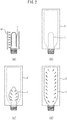
- FIG. 1 shows a plastic bottle preform 1.
- the preform 1 is molded from a resin by injection molding or PCM (preform compression molding).
- the preform 1 comprises an opening 1a fitting with a plastic bottle cap, a cylindrical body 1b adjacent the opening 1a, and a bottom 1c for closing one end of the cylindrical body 1b, and has a test tube-like shape.
- Male threading which engages with female threading of the plastic bottle cap is formed on the outer peripheral surface of the opening 1a.
- the end of the preform 1 on the opening 1a side is open.
- a barrier coating is formed on the outer peripheral surface of the preform 1.
- the barrier coating is formed by applying a coating solution to the outer peripheral surface of the preform 1 and drying the applied coating solution.
- the barrier coating can reduce the transmission of gases such as oxygen and carbon dioxide into and out of the plastic bottle molded from the preform 1 and extend the shelf life of beverages and the like contained in the plastic bottle.
- the barrier coating can also improve the scratch resistance and moisture resistance of the plastic bottle.
- FIGS. 2(a) to (d) show the stretch blow molding method for molding a plastic bottle 3 from a preform 1.
- the preform 1 is heated by a preform heating device 40.
- the preform 1 is inserted into a mold 2 and the mold 2 is closed.
- the preform 1 is stretched longitudinally with a stretching rod (not shown) and transversely with pressurized air.
- FIG. 2(d) once the preform 1 has expanded to the desired shape, the inner surface of the plastic bottle 3 is cooled by cooling air, and the plastic bottle 3 is ultimately removed from the mold 2.
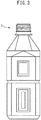
- FIG. 3 shows the plastic bottle 3 molded from the preform 1.
- FIG. 4 is a schematic front view of the main portions of a preform coating device 5 according to the first embodiment of the present invention.
- the preform coating device 5 is configured so as to form a barrier coating on the outer peripheral surface of the preform 1 by applying a coating solution to the preform 1 and drying the applied coating solution.
- the preform coating device 5 comprises a dispenser 6 for applying a coating solution to the preform 1, and a dryer 7 for drying the applied coating solution.
- the dryer 7 is arranged spaced apart from the dispenser 6. In the present embodiment, the dryer 7 is arranged horizontally spaced apart from the dispenser 6.
- the preform coating device 5 further comprises a conveyance part 8 for conveying the preform 1.
- the conveyance part 8 moves the preform 1 from the location of the dispenser 6 toward the location of the dryer 7.
- the conveyance part 8 is a belt conveyor.
- the conveyance part 8 includes two pulleys 81a,81b, and a belt 82 hung on the pulleys 81a,81b.
- the pulleys 81a,81b are rotatably secured to a pulley support plate 20 which extends in the horizontal direction.
- the pulley support plate 20 is supported by two supporting columns 21a,21b which extend in the vertical direction.
- One of the pulleys 81a,81b is driven by a motor (not illustrated).
- the conveyance part 8 can convey a preform 1.
- the number of pulleys may be three or more.
- the conveyance part 8 may be another mechanism such as a chain conveyor, as long as it can convey the preform 1.
- the preform coating device 5 further comprises a plurality (two in the present embodiment) of rotary retention parts 9 which horizontally retain the preform 1 and which rotate the preform 1 about the axis A of the preform 1.
- the plural rotary retention parts 9 are arranged at predetermined intervals along the conveyance path of the conveyance part 8.
- the intervals between the plurality of rotary retention parts 9 can be arbitrarily determined in consideration of, for example, the pitch of the belt or chain of the conveyance part 8 and the diameter of the preform.
- the preform coating device 5 may comprise three or more rotary retention parts 9.
- the preform coating device 5 may comprise a plurality of rotary retention parts 9 along the entire circumference of the conveyance path of the conveyance part 8.
- the intervals between the plurality of rotary retention parts 9 be as small as possible.
- the plurality of rotary retention parts 9 may be divided into a plurality of batches. In this case, the intervals between batches may be different than the intervals between the rotary retention parts 9.
- FIG. 5 is a schematic partial side view of the preform coating device 5 at the time of application of the coating solution. Note that FIG. 5 shows the preform coating device 5 as viewed from the right side in FIG. 4 , and thus, only a single rotary retention part 9 (and only a single nozzle 61) is shown.
- the rotary retention part 9 includes a chuck 91 for retaining the opening 1a of the preform 1, and a rotary shaft 92 connected to the chuck 91.
- the rotary retention part 9 retains the preform 1 in the horizontal direction by retaining the opening 1a of the preform 1 with the chuck 91.
- the preform 1 is cantilevered by the rotary retention part 9.
- the chuck 91 is, for example, a vacuum chuck that suctions the preform 1 with air, or a mechanical chuck that mechanically retains the preform 1. Note that though the chuck 91 in the present embodiment retains the interior of the opening 1a of the preform 1, the chuck 91 may retain the exterior of the opening 1a of the preform 1.
- the rotary shaft 92 is driven by a motor (not illustrated) and rotates together with the chuck 91.
- the axis of the rotary shaft 92 is co-axial with the axis A of the preform 1.
- the preform 1 can be rotated about the axis A thereof.
- the rotary retention parts 9 are connected to the belt 82.
- the conveyance part 8 can convey the preforms 1 by moving the rotary retention part 9.
- the dispenser 6 is arranged above the cylindrical body 1b.
- the dispenser 6 houses the coating solution and discharges the coating solution toward the preform 1.
- the coating solution is supplied to the dispenser 6 by a pump or the like.
- FIG. 6 is a partial front view of the dispenser 6.
- the dispenser 6 comprises a head 60, a shaft 62, a plate 63, and a plurality (two in the present embodiment) of nozzles 61. Note that the dispenser 6 may have three or more nozzles 61.
- the dispenser 6 can be affixed to, for example, an unillustrated frame or floor, with using an arbitrary fastener.
- the head 60 may have a mechanism for feeding coating solution to the nozzles 61, for example, a uniaxial eccentric screw pump or other type of pump, or a pneumatic dispenser which discharges the coating solution by the power of compressed air.
- a mechanism for feeding coating solution to the nozzles 61 for example, a uniaxial eccentric screw pump or other type of pump, or a pneumatic dispenser which discharges the coating solution by the power of compressed air.
- the shaft 62 extends downwardly from the head 60.
- the shaft 62 has a flow path which is in fluid communication with the discharge mechanism of the head 60.
- the plate 63 has an elongate plate-like shape and is attached to the lower end of the shaft 62 so that the longitudinal direction thereof is perpendicular to the central axis of the shaft 62 and is oriented in the conveyance direction of the conveyor part 8.
- the plate 63 has a flow path which is in fluid communication with the flow path of the shaft 62 and this flow path is divided in two directions along the longitudinal direction of the plate 63.
- Each nozzle 61 extends downward from the lower surface of the plate 63.
- the plurality of nozzles 61 are attached to the plate 63 at predetermined intervals along the longitudinal direction of the plate 63 (i.e. along the conveyance path of the conveyance part 8).
- the intervals between the plurality of nozzles 61 are set so as to be equal to the distances between the plurality of rotary retention parts 9.
- Each nozzle 61 has a flow path which is in fluid communication with one of the divided flow paths of the plate 63.
- Each nozzle 61 has a length adjustment mechanism 65 and a flow rate adjustment mechanism 66.
- the length adjustment mechanism 65 includes male threading 65a formed on the upper end of the nozzle 61 and a nut 65b.
- the male threading 65a can engage with female threading (not illustrated) formed in the plate 63, and by securing the nozzle 61 with the nut 65b at a predetermined position relative to the plate 63, the distance from the head 60 to the slot of the respective nozzle 61 can be adjusted independent of the other nozzle 61.
- the flow rate adjustment mechanism 66 may have a structure such as a throttle valve.
- the flow rate adjustment mechanism 66 can be configured, for example, to narrow the flow path of the nozzle 61 by tightening the nut 66a and to widen the flow path of the nozzle 61 by loosening the nut 66a. According to such a configuration, the discharge amount of coating solution from each nozzle 61 can be adjusted.
- a slot is formed in the tip of each nozzle 61.
- Each nozzle 61 discharges the coating solution in a plane-like form from the slot towards the cylindrical body 1b of the preform 1.
- the width of the slot (the length in the axial direction of the preform 1) can be adjusted and is, for example, 15 mm to 40 mm.
- the vertical width of the slot (the length in the direction orthogonal to the axial direction of the preform 1) can be adjusted and is, for example, 0.1 mm to 1.0 mm.
- the dispenser 6 can move in the vertical direction, as illustrated by arrow Z of FIG. 6 .
- the distance between the slot of the nozzle 61 and the cylindrical body 1b of the preform 1 can be adjusted.
- the coating solution is discharged from above the preform 1 in the present embodiment, the coating solution may be discharged in other directions, for example, from below the preform 1.
- the dispenser 6 is configured so that the distance between the slot of the nozzle 61 and the cylindrical body 1b of the preform 1 can be adjusted.
- the conveyance part 8 does not move the rotary retention parts 9 while the dispenser 6 discharges coating solution.
- the rotary retention part 9 rotates the preform 1 while the dispenser 6 discharges coating solution.
- the dispenser 6 continues to discharge coating solution while the preform 1 makes substantially one rotation.
- the discharged coating solution is wound up by the outer peripheral surface of the cylindrical body 1b of the preform 1.
- coating solution is applied to the entirety of the outer peripheral surface of the cylindrical body 1b of the preform 1.
- the thickness of the coating solution is prevented from gradually increasing toward the bottom 1c of the preform 1 due to gravity.
- the preform 1 is cantilevered by the rotary retention part 9, the outer peripheral surface of the preform 1 on the bottom 1c side tends to move away from the axis A of the preform 1 by the rotation of the preform 1. In other words, the rotation of the preform 1 causes eccentricity of the preform 1. As a result, the thickness of the coating solution applied to the preform 1 may not be uniform.
- the preform coating device 5 further comprises a preform support part 10.
- the preform support part 10 can have, for example, a flat surface which comes into contact with the preform 1. Chamfering for smooth contact with the moving preform 1 may be formed on the surface of the preform support part 10 which comes into contact with the preform 1.
- the preform support part 10 is supported and secured by a supporting column 21c.
- the preform support part 10 rotatably supports the preform 1 at least while the dispenser 6 discharges the coating solution.
- the preform support part 10 supports the end of the cylindrical body 1b of the preform 1 at the bottom side 1c so as not to contact the applied coating solution.
- the preform support part 10 which contacts the preform 1 is made of a resin, and is preferably made of polyoxymethylene (POM).
- POM polyoxymethylene
- the preform support part 10 can support a plurality of preforms 1 (refer to FIG. 4 ).
- the present inventors have discovered that in some cases (for example, when the preform 1 is for a plastic bottle for a carbonated beverage and is relatively long and/or heavy), eccentricity of the preform 1 may occur even though the preform 1 is supported at both ends by the rotary retention part 9 and the preform support part 10.
- the present inventors have discovered that the vertical positional accuracy and/or retention accuracy of the chuck 91 of the rotary retention part 9 may influence the eccentricity of the preform 1.
- the present inventors have realized that by supporting the outer peripheral surface of the opening 1a of the preform 1, the eccentricity of the preform 1 can be reduced regardless of the vertical positional accuracy and/or retention accuracy of the chuck 91.
- the preform coating device 5 further comprises an opening support part 11.
- the opening support part 11 can have, for example, a flat surface which comes into contact with the opening 1a. Chamfering for smooth contact with the moving preform 1 may be formed on the surface of the opening support part 11 which comes into contact with the preform 1.
- the opening support part 11 is supported by a supporting column 21d.
- the opening support part 11 rotatably supports the outer peripheral surface of the opening 1a of the preform 1 at least while the dispenser 6 discharges the coating solution.
- the opening 1a of the preform 1 is arranged at a fixed position by the opening support part 11 regardless of the vertical positional accuracy and/or the retention accuracy of the chuck 91.
- eccentricity of the preform 1 can be effectively suppressed.
- the opening support part 11 can support various portions of the outer peripheral surface of the opening 1a (i.e. portions of the preform 1 to which the coating solution is not applied and which include an opening).
- the opening support part 11 may support one or more locations selected from the radially outermost protruding portion from the axis, the portion on which the male threading is formed, and the portion between the radially outermost protruding portion and the cylindrical body 1b.
- the opening support part 11 can support portions which do not interfere with the chuck 91.
- At least the portion of the opening support part 11 which comes into contact with the opening 1a is made of a resin, and is preferably made of polyoxymethylene. This can prevent the opening 1a from being damaged by the contact between the opening support part 11 and the opening 1a.
- the opening support part 11 supports the openings 1a of a plurality of preforms 1.
- the preform 1 is conveyed to the position of the dryer 7 by the conveyance part 8.
- the conveyance part 8 conveys the horizontally retained preform 1.
- the dryer 7 is, for example, a carbon heater or a far-infrared heater. Both a carbon heater and a far-infrared heater may be used as the dryer 7.
- the dryer 7 may be configured so as to dry the coating solution with light or gas.
- the rotary retention part 9 rotates the preform 1 during drying of the coating solution by the dryer 7. As a result, the coating solution applied to the preform 1 can be uniformly dried.
- the conveyance part 8 conveys the preform 1 to downstream of the dryer 7. Thereafter, the rotary retention part 9 releases the preform 1 and the preform 1 is removed from the preform coating device 5.
- the preform coating device 5 formation of a barrier coating on the outer peripheral surface of the preform 1 can be automated.
- the coating solution used in the present embodiment is a barrier coating solution having a gas barrier function, such as a polyvinyl alcohol (PVA) solution.
- the coating solution may be a solution of a barrier resin such as a water-soluble polyamide, water-soluble polyester, polyvinylidene chloride (PVDC), polyacrylonitrile, ethylene-vinyl alcohol copolymer resin (EVOH), or polyglycolic acid.
- the coating solution may be obtained by adding an inorganic material to any of the solutions described above.
- the viscosity of the barrier coating solution is, for example, 25 mPa ⁇ s or more and 10000 mPa ⁇ s or less.
- a protective coating solution for protecting the barrier coating solution may be further applied on the barrier coating solution.
- the protective coating solution is a water-insoluble coating agent such as, for example, a polyolefin dispersion solution, various modified polyolefin dispersion solutions, or polyvinyl butyral (PVB).
- the viscosity of the protective coating solution may be, for example, 0.5 mPa ⁇ s or more and 100 mPa ⁇ s or less.
- the protective coating solution can be applied to the preform 1 using the preform coating device 5.
- the dispenser 6 comprises a plurality of nozzles 61 for a single head 60.
- the coating solution can be discharged simultaneously by a plurality of nozzles 61 without an increase in the number of relatively expensive heads 60.
- the intervals between the plurality of nozzles 61 is set so as to be equal to the intervals between the plurality of retention parts 9.
- a coating can be formed simultaneously on a plurality of preforms 1 without enlarging the conveyance part 8. Therefore, a coating can be formed on a larger number of preforms in a short period of time without increasing the installation area or production costs.
- each nozzle 61 comprises a length adjustment mechanism 65 for adjusting the distance from the head 60 to the slot of the nozzle 61.
- the interval between the slot of the nozzle 61 and the preform 1 can be adjusted without changing the position of the head 60.
- the distance from the head 60 to the slot of the nozzle 61 can be adjusted so that coatings can be equally formed on the plural preforms 1.
- each nozzle 61 comprises a flow rate adjustment mechanism 66 for adjusting the discharge amount of the coating solution from the nozzle 61.
- the discharge amount of the coating solution from the nozzle 61 can be adjusted so that coatings are equally formed on a plurality of preforms 1.
- the preform coating device 5 comprises a preform support part 10 for supporting the end of the cylindrical body 1b of the preform 1 on the bottom side 1c, and an opening support part 11 for supporting the outer peripheral surface of the opening 1a of the preform 1.
- a preform support part 10 for supporting the end of the cylindrical body 1b of the preform 1 on the bottom side 1c
- an opening support part 11 for supporting the outer peripheral surface of the opening 1a of the preform 1.
- the opening support part 11 can support various portions of the outer peripheral surface of the opening 1a of the preform 1.
- the opening support part 11 may support the radially outermost protruding portion from the axis A.
- the rotary retention part 9 can support various portions of the opening 1a of the preform 1.
- the rotary retention part 9 may retain the interior of the opening 1a of the preform 1.
- the preform 1 may be for a plastic bottle for a carbonated beverage.
- Plastic bottles for carbonated beverages may be formed so as to have a high strength and thus a higher weight in order to withstand internal pressures.
- eccentricity of preform 1 may occur due to the high weight. Therefore, the effect of suppressing eccentricity can be suitably exhibited.
- FIG. 7 is a schematic front view of the main portions of the preform coating device 50 according to the second embodiment of the present invention.
- the preform coating device 50 differs from the preform coating device 5 according to the first embodiment mainly in that it comprises two dispensers 6A, 6B.
- the dispenser 6A differs from the dispenser 6 according to the first embodiment in that the intervals of the plurality (two in the present embodiment) of nozzles 61 are larger than the intervals between the plurality of nozzles 61 of the dispenser 6 according to the first embodiment.
- the other components of the dispenser 6A can be configured in the same manner as the corresponding components of the dispenser 6.
- dispenser 6B has the same structure as the dispenser 6A, dispenser 6B is arranged in the opposite direction to the dispenser 6A. Specifically, like the dispenser 6 according to the first embodiment, the dispenser 6A has a plurality of downward-facing nozzles 61 for discharging coating solution downwardly and is arranged above the preform 1 to be coated. In contrast, the dispenser 6B has a plurality of upward-facing nozzles 61 for discharging coating solution upwardly and is arranged below the preform 1 to be coated.
- the plurality of nozzles 61 of the dispenser 6A and the plurality of nozzles 61 of the dispenser 6B are alternatingly arranged in the direction along the conveyance path of the conveyance part 8.
- the dispenser 6A and the dispenser 6B include overlapping regions in the direction along the conveyance path of the conveyance part 8.
- the preform support part 10 and the opening support part 11 (not illustrated in FIG. 7 ), which are arranged below the downward-facing nozzle 61, can be configured in substantially the same manner as in the first embodiment described above. Note that in the present embodiment, a preform support part 10 and an opening support part 11 are provided for each of the plurality of downward-facing nozzles 61, as shown in FIG. 7 . Thus, the preforms 1 are individually supported. Also note that in Fig. 7 , a supporting column 21c on the right side is not illustrated, in order to show the dispenser 6B.
- FIG. 8 is a schematic partial side view of the dispenser 6B including an upward-facing nozzle 61 at the time of application of coating solution. Note that FIG. 8 shows the dispenser 6B as viewed from the right side in FIG. 7 , and thus, only a single nozzle 61 is shown. As shown in FIG. 8 , the upward-facing nozzle 61 discharges coating solution upwardly.
- a preform support part 10 and an opening support part 11 are arranged above the nozzle 61.
- the preform support part 10 and the opening support part 11 can be affixed to, for example, a support 21e and a support 21f, respectively.
- the support 21e and the support 21f can be hung on, for example, a support 21g which extends in the horizontal direction.
- the support 21g can be affixed to, for example, an unillustrated frame, using an arbitrary fastener.
- the preform coating device 50 according to the second embodiment can achieve the same effects as the preform coating device 5 according to the first embodiment.
- the preform coating device 50 further comprises a dispenser 6B having the same structure as the dispenser 6A, the dispenser 6B is arranged below the preform 1, and the dispenser 6A is arranged above the preform 1.
- a dispenser 6B having the same structure as the dispenser 6A
- the dispenser 6B is arranged below the preform 1
- the dispenser 6A is arranged above the preform 1.
- gas may enter from the slot and bubbles may be present inside the dispenser. Since bubbles can affect the quality of the coating, it is preferable that bubbles be removed from inside the dispenser.
- the dispenser 6B which discharges the coating solution upward, air bubbles naturally rise in the nozzle and are discharged from the slot. Therefore bubbles can easily be removed from the dispenser 6B.
- the plurality of nozzles 61 of the dispenser 6A and the plurality of nozzles 61 of the dispenser 6B are alternatingly arranged in the direction of the conveyance path.
- the dispensers 6A,6B have overlapping regions in the direction along the conveyance path.
- the area for arrangement of the dispensers 6A,6B can be reduced.
- enlargement of the device can be prevented.
- the dispensers 6A,6B have overlapping regions in the direction along the conveyance path.
- the dispensers 6A,6B need not have overlapping regions in the direction along the conveyance path, and the plurality of downward-facing nozzles 61 may be arranged upstream or downstream of the plurality of upward-facing nozzles 61.
Landscapes
- Engineering & Computer Science (AREA)
- Mechanical Engineering (AREA)
- Manufacturing & Machinery (AREA)
- Physics & Mathematics (AREA)
- Geometry (AREA)
- Blow-Moulding Or Thermoforming Of Plastics Or The Like (AREA)
- Coating Apparatus (AREA)
- Processing And Handling Of Plastics And Other Materials For Molding In General (AREA)
Applications Claiming Priority (2)
| Application Number | Priority Date | Filing Date | Title |
|---|---|---|---|
| JP2017248456 | 2017-12-25 | ||
| PCT/JP2018/047669 WO2019131681A1 (ja) | 2017-12-25 | 2018-12-25 | プリフォームコーティング装置 |
Publications (2)
| Publication Number | Publication Date |
|---|---|
| EP3733302A1 true EP3733302A1 (de) | 2020-11-04 |
| EP3733302A4 EP3733302A4 (de) | 2021-09-01 |
Family
ID=67063643
Family Applications (1)
| Application Number | Title | Priority Date | Filing Date |
|---|---|---|---|
| EP18896279.9A Withdrawn EP3733302A4 (de) | 2017-12-25 | 2018-12-25 | Vorformbeschichtungsvorrichtung |
Country Status (6)
| Country | Link |
|---|---|
| US (1) | US11260417B2 (de) |
| EP (1) | EP3733302A4 (de) |
| JP (1) | JP7016888B2 (de) |
| CN (1) | CN111491744A (de) |
| AU (1) | AU2018397882B2 (de) |
| WO (1) | WO2019131681A1 (de) |
Families Citing this family (3)
| Publication number | Priority date | Publication date | Assignee | Title |
|---|---|---|---|---|
| ES2884873T3 (es) | 2015-09-30 | 2021-12-13 | Suntory Holdings Ltd | Dispositivo de revestimiento de preformas y método de revestimiento de preformas |
| CN109693361B (zh) * | 2019-01-15 | 2021-02-26 | 亚普汽车部件股份有限公司 | 中空体成型辅具及成型方法 |
| DE102019120274A1 (de) * | 2019-07-26 | 2021-01-28 | Krones Ag | System und Verfahren zum Herstellen eines Behälters |
Family Cites Families (32)
| Publication number | Priority date | Publication date | Assignee | Title |
|---|---|---|---|---|
| CA1019210A (en) | 1972-12-23 | 1977-10-18 | Toyo Ink Mfg. Co. | Coating method and apparatus |
| JPS5226531B2 (de) | 1973-10-19 | 1977-07-14 | ||
| JPS5022840A (de) | 1973-06-28 | 1975-03-11 | ||
| JPS5253947A (en) | 1975-10-28 | 1977-04-30 | Kyowa Denki Kagaku Kk | Method for coting circumference of bottle |
| US4127633A (en) | 1976-04-21 | 1978-11-28 | Imperial Chemical Industries Limited | Process for fabricating biaxially oriented container of polyethylene terephthalate coated with a copolymer of vinylidene chloride |
| JPS59216654A (ja) | 1983-05-24 | 1984-12-06 | Toyo Seikan Kaisha Ltd | パリソンに塗膜を被覆する装置 |
| EP0142583B1 (de) | 1983-11-14 | 1987-05-20 | Kyowa Denki Kagaku K.K. | Verfahren und Vorrichtung zum Beschichten von Behältern mit Beschichtungsmaterial |
| JPS61118757A (ja) | 1984-11-15 | 1986-06-06 | Minolta Camera Co Ltd | 電子写真用感光体ドラムの製造方法 |
| US5039560A (en) | 1989-05-26 | 1991-08-13 | Sweetheart Cup Company | Method for producing high gloss cup |
| JP2983890B2 (ja) | 1995-09-14 | 1999-11-29 | 岐阜プラスチック工業株式会社 | 塗布装置及び同塗布装置を備えたコーティングシステム |
| JPH09276667A (ja) | 1996-04-15 | 1997-10-28 | Kitz Corp | 耐溶剤性中空糸状半透膜型カートリッジ及びその半透膜型モジュール |
| JP4139456B2 (ja) | 1997-10-02 | 2008-08-27 | 三菱レイヨン株式会社 | 脱気膜 |
| TWI250934B (en) * | 1997-10-17 | 2006-03-11 | Advancsd Plastics Technologies | Barrier-coated polyester articles and the fabrication method thereof |
| JP2000126559A (ja) | 1998-10-21 | 2000-05-09 | Fuji Photo Film Co Ltd | 膜脱気モジュールの洗浄方法 |
| JP2001129368A (ja) | 1999-08-20 | 2001-05-15 | Herushii Techno Chem:Kk | 気液分離モジュール |
| US7048975B1 (en) | 1999-10-15 | 2006-05-23 | Kao Corporation | Pulp molded container |
| JP4158962B2 (ja) | 2001-06-01 | 2008-10-01 | 漢拏空調株式会社 | 圧縮機ピストンコーティング方法 |
| DE10226017A1 (de) | 2002-06-12 | 2003-12-24 | Krones Ag | Verfahren und Vorrichtung zum Herstellen von Hohlkörpern |
| EG23499A (en) | 2002-07-03 | 2006-01-17 | Advanced Plastics Technologies | Dip, spray, and flow coating process for forming coated articles |
| US20070082135A1 (en) | 2005-10-06 | 2007-04-12 | Vincent Lee | Coating glass containers and labels |
| JP5154510B2 (ja) | 2009-06-05 | 2013-02-27 | 東京エレクトロン株式会社 | プライミング処理方法及びプライミング処理装置 |
| US20110034992A1 (en) | 2009-08-04 | 2011-02-10 | Papp John E | Stent and Method of Coating Same |
| JP5789546B2 (ja) | 2011-04-26 | 2015-10-07 | 東京エレクトロン株式会社 | 塗布処理装置、塗布現像処理システム、並びに塗布処理方法及びその塗布処理方法を実行させるためのプログラムを記録した記録媒体 |
| EP2532600B1 (de) | 2011-06-06 | 2020-01-22 | Kuraray Europe GmbH | Kunststoffbehälter mit gasbarrierebeschichtung und optionaler wasserabweisender innenbeschichtung |
| JP6037879B2 (ja) | 2013-02-13 | 2016-12-07 | サントリーホールディングス株式会社 | ガスバリアコーティングを有するプラスチックボトル用プリフォーム |
| CN203184149U (zh) * | 2013-04-11 | 2013-09-11 | 浙江凯博压力容器有限公司 | 一种复合气瓶喷涂烘干一体装置 |
| JP2015199012A (ja) | 2014-04-04 | 2015-11-12 | サントリーホールディングス株式会社 | プリフォームコーティング装置、プリフォームの製造方法及びプラスチックボトルの製造方法 |
| FR3035088B1 (fr) | 2015-04-16 | 2019-05-17 | Sidel Participations | "procede d'alignement et de redressement de preformes par centrifugation et dispositif associe" |
| CN105170371B (zh) | 2015-09-22 | 2017-07-21 | 山东龙泉管道工程股份有限公司 | 口径小于1400mm卧式钢筒混凝土管外防腐全自动喷涂装置 |
| JP6537429B2 (ja) | 2015-09-30 | 2019-07-03 | サントリーホールディングス株式会社 | プリフォームコーティング装置 |
| JP6537426B2 (ja) | 2015-09-30 | 2019-07-03 | サントリーホールディングス株式会社 | プリフォームコーティング装置及びプリフォームコーティング方法 |
| ES2884873T3 (es) | 2015-09-30 | 2021-12-13 | Suntory Holdings Ltd | Dispositivo de revestimiento de preformas y método de revestimiento de preformas |
-
2018
- 2018-12-25 JP JP2019562054A patent/JP7016888B2/ja active Active
- 2018-12-25 CN CN201880082691.0A patent/CN111491744A/zh active Pending
- 2018-12-25 AU AU2018397882A patent/AU2018397882B2/en not_active Ceased
- 2018-12-25 EP EP18896279.9A patent/EP3733302A4/de not_active Withdrawn
- 2018-12-25 US US16/957,542 patent/US11260417B2/en not_active Expired - Fee Related
- 2018-12-25 WO PCT/JP2018/047669 patent/WO2019131681A1/ja not_active Ceased
Also Published As
| Publication number | Publication date |
|---|---|
| JP7016888B2 (ja) | 2022-02-07 |
| AU2018397882B2 (en) | 2021-11-11 |
| AU2018397882A1 (en) | 2020-07-30 |
| US11260417B2 (en) | 2022-03-01 |
| JPWO2019131681A1 (ja) | 2020-12-24 |
| US20210060600A1 (en) | 2021-03-04 |
| CN111491744A (zh) | 2020-08-04 |
| WO2019131681A1 (ja) | 2019-07-04 |
| EP3733302A4 (de) | 2021-09-01 |
Similar Documents
| Publication | Publication Date | Title |
|---|---|---|
| CN108025330B (zh) | 预塑件涂敷装置及预塑件涂敷方法 | |
| JP6537429B2 (ja) | プリフォームコーティング装置 | |
| AU2018397882B2 (en) | Preform coating device | |
| US11511310B2 (en) | Preform coating device | |
| AU2018395353B2 (en) | Preform coating device | |
| AU2018395352B2 (en) | Preform coating device |
Legal Events
| Date | Code | Title | Description |
|---|---|---|---|
| STAA | Information on the status of an ep patent application or granted ep patent |
Free format text: STATUS: THE INTERNATIONAL PUBLICATION HAS BEEN MADE |
|
| PUAI | Public reference made under article 153(3) epc to a published international application that has entered the european phase |
Free format text: ORIGINAL CODE: 0009012 |
|
| STAA | Information on the status of an ep patent application or granted ep patent |
Free format text: STATUS: REQUEST FOR EXAMINATION WAS MADE |
|
| 17P | Request for examination filed |
Effective date: 20200709 |
|
| AK | Designated contracting states |
Kind code of ref document: A1 Designated state(s): AL AT BE BG CH CY CZ DE DK EE ES FI FR GB GR HR HU IE IS IT LI LT LU LV MC MK MT NL NO PL PT RO RS SE SI SK SM TR |
|
| AX | Request for extension of the european patent |
Extension state: BA ME |
|
| DAV | Request for validation of the european patent (deleted) | ||
| DAX | Request for extension of the european patent (deleted) | ||
| A4 | Supplementary search report drawn up and despatched |
Effective date: 20210804 |
|
| RIC1 | Information provided on ipc code assigned before grant |
Ipc: B05C 5/00 20060101AFI20210729BHEP Ipc: B05C 9/14 20060101ALI20210729BHEP Ipc: B05C 13/02 20060101ALI20210729BHEP Ipc: B29C 49/22 20060101ALI20210729BHEP Ipc: B29B 11/14 20060101ALI20210729BHEP Ipc: B05D 1/00 20060101ALN20210729BHEP Ipc: B05D 1/26 20060101ALN20210729BHEP Ipc: B29B 11/08 20060101ALN20210729BHEP Ipc: B29C 49/02 20060101ALN20210729BHEP Ipc: B29L 31/00 20060101ALN20210729BHEP Ipc: B29C 49/12 20060101ALN20210729BHEP Ipc: B29K 23/00 20060101ALN20210729BHEP Ipc: B29K 27/00 20060101ALN20210729BHEP Ipc: B29K 31/00 20060101ALN20210729BHEP Ipc: B29L 9/00 20060101ALN20210729BHEP |
|
| REG | Reference to a national code |
Ref country code: DE Ref legal event code: R079 Free format text: PREVIOUS MAIN CLASS: B05C0005000000 Ipc: B29C0049020000 |
|
| GRAP | Despatch of communication of intention to grant a patent |
Free format text: ORIGINAL CODE: EPIDOSNIGR1 |
|
| STAA | Information on the status of an ep patent application or granted ep patent |
Free format text: STATUS: GRANT OF PATENT IS INTENDED |
|
| RIC1 | Information provided on ipc code assigned before grant |
Ipc: B05B 1/14 20060101ALN20230310BHEP Ipc: B05B 1/04 20060101ALN20230310BHEP Ipc: B29L 9/00 20060101ALN20230310BHEP Ipc: B29K 31/00 20060101ALN20230310BHEP Ipc: B29K 27/00 20060101ALN20230310BHEP Ipc: B29K 23/00 20060101ALN20230310BHEP Ipc: B29C 49/12 20060101ALN20230310BHEP Ipc: B29L 31/00 20060101ALN20230310BHEP Ipc: B29B 11/08 20060101ALN20230310BHEP Ipc: B05D 1/26 20060101ALN20230310BHEP Ipc: B05D 1/00 20060101ALN20230310BHEP Ipc: B05C 5/02 20060101ALI20230310BHEP Ipc: B05B 15/65 20180101ALI20230310BHEP Ipc: B05C 13/02 20060101ALI20230310BHEP Ipc: B05C 9/14 20060101ALI20230310BHEP Ipc: B29C 49/22 20060101ALI20230310BHEP Ipc: B29B 11/14 20060101ALI20230310BHEP Ipc: B29C 49/02 20060101AFI20230310BHEP |
|
| INTG | Intention to grant announced |
Effective date: 20230403 |
|
| STAA | Information on the status of an ep patent application or granted ep patent |
Free format text: STATUS: THE APPLICATION IS DEEMED TO BE WITHDRAWN |
|
| 18D | Application deemed to be withdrawn |
Effective date: 20230815 |