EP3733349B1 - Spannvorrichtung für eine schraubverbindung - Google Patents
Spannvorrichtung für eine schraubverbindung Download PDFInfo
- Publication number
- EP3733349B1 EP3733349B1 EP20167492.6A EP20167492A EP3733349B1 EP 3733349 B1 EP3733349 B1 EP 3733349B1 EP 20167492 A EP20167492 A EP 20167492A EP 3733349 B1 EP3733349 B1 EP 3733349B1
- Authority
- EP
- European Patent Office
- Prior art keywords
- clutch
- clamping device
- torque
- support tube
- drive
- Prior art date
- Legal status (The legal status is an assumption and is not a legal conclusion. Google has not performed a legal analysis and makes no representation as to the accuracy of the status listed.)
- Active
Links
Images


Classifications
-
- F—MECHANICAL ENGINEERING; LIGHTING; HEATING; WEAPONS; BLASTING
- F16—ENGINEERING ELEMENTS AND UNITS; GENERAL MEASURES FOR PRODUCING AND MAINTAINING EFFECTIVE FUNCTIONING OF MACHINES OR INSTALLATIONS; THERMAL INSULATION IN GENERAL
- F16B—DEVICES FOR FASTENING OR SECURING CONSTRUCTIONAL ELEMENTS OR MACHINE PARTS TOGETHER, e.g. NAILS, BOLTS, CIRCLIPS, CLAMPS, CLIPS OR WEDGES; JOINTS OR JOINTING
- F16B2/00—Friction-grip releasable fastenings
- F16B2/02—Clamps, i.e. with gripping action effected by positive means other than the inherent resistance to deformation of the material of the fastening
- F16B2/06—Clamps, i.e. with gripping action effected by positive means other than the inherent resistance to deformation of the material of the fastening external, i.e. with contracting action
-
- B—PERFORMING OPERATIONS; TRANSPORTING
- B23—MACHINE TOOLS; METAL-WORKING NOT OTHERWISE PROVIDED FOR
- B23P—METAL-WORKING NOT OTHERWISE PROVIDED FOR; COMBINED OPERATIONS; UNIVERSAL MACHINE TOOLS
- B23P19/00—Machines for simply fitting together or separating metal parts or objects, or metal and non-metal parts, whether or not involving some deformation; Tools or devices therefor so far as not provided for in other classes
- B23P19/04—Machines for simply fitting together or separating metal parts or objects, or metal and non-metal parts, whether or not involving some deformation; Tools or devices therefor so far as not provided for in other classes for assembling or disassembling parts
- B23P19/06—Screw or nut setting or loosening machines
-
- B—PERFORMING OPERATIONS; TRANSPORTING
- B25—HAND TOOLS; PORTABLE POWER-DRIVEN TOOLS; MANIPULATORS
- B25B—TOOLS OR BENCH DEVICES NOT OTHERWISE PROVIDED FOR, FOR FASTENING, CONNECTING, DISENGAGING, OR HOLDING
- B25B17/00—Hand-driven gear-operated wrenches or screwdrivers
-
- B—PERFORMING OPERATIONS; TRANSPORTING
- B25—HAND TOOLS; PORTABLE POWER-DRIVEN TOOLS; MANIPULATORS
- B25B—TOOLS OR BENCH DEVICES NOT OTHERWISE PROVIDED FOR, FOR FASTENING, CONNECTING, DISENGAGING, OR HOLDING
- B25B29/00—Accessories
- B25B29/02—Bolt tensioners
Definitions
- the invention relates to a tensioning device for a screw connection consisting of a threaded bolt and a threaded nut, with a support tube surrounding the threaded nut, a cylinder housing as an extension of the support tube, a piston which can be moved in the cylinder housing by means of hydraulic pressure, an interchangeable bush which can be carried along axially by the piston and which is equipped with a internal thread for screwing the interchangeable socket to the threaded bolt, a driver arranged inside the support tube and connectable to the threaded nut in a non-positive or positive manner, and a gear arrangement between a drive element which is rotatably mounted outside of the support tube and is provided with a tool surface for applying a hand tool, and the taker.
- Clamping devices for clamping screw connections with these features are from DE 10 2004 043 145 B3 , the WO2010/054959 A1 and the WO 2008/092768 A2 known.
- the clamping device has a hydraulic clamping cylinder, which is equipped with a gear on the outside. While hydraulic pressure is fed into the clamping cylinder, the threaded nut is tightened.
- a driver in the form of a rotary sleeve positively surrounding the threaded nut is located in a support tube, which forms the lower part of the clamping cylinder.
- the rotary sleeve is driven manually by means of a torque wrench attached to a tool surface, with a gear arrangement forming the drive path between the tool surface for the torque wrench and the rotary sleeve.
- a drive housing is fastened to the outside of the tensioning device to accommodate and pivot the individual gear elements of the gear arrangement.
- the DE 2 061 037 A1 also shows a clamping device.
- the retightening or turning of the threaded nut is not done by hand, but using a drive designed only for this purpose.
- An electric motor serves as the drive, the power of which is controlled by monitoring the electrical resistance.
- the electrical resistance which increases with the drive load, is used to interrupt the further voltage supply to the electric motor and thus avoid excessive tightening torques on the threaded nut.
- the one in the U.S. 5,452,629 The proposed solution is expensive in terms of equipment, since it requires its own electrical drive only for retightening or turning the threaded nut and control devices in the electrical supply of the drive.
- the invention is based on the object, in a bolt tensioning device working with a hydraulic tensioning cylinder, with mechanical devices that are simple in terms of equipment Means to safely avoid excessive forces when tightening or turning the threaded nut.
- a torque-dependent clutch is part of the gear arrangement, by means of which the threaded nut is turned.
- This clutch can be a friction slip clutch, for example, which slips above a certain torque threshold.
- the torque with which the threaded nut is tightened or turned during activation of the hydraulic clamping cylinder is subject to a clear limitation that cannot be exceeded even in the event of incorrect operation.
- This restriction is largely independent of user actions. This does not depend on initially making settings correctly, such as setting the correct release value when using a manual torque wrench.
- the torque-dependent clutch reliably ensures that maximum values cannot be exceeded.
- the torque-dependent clutch is designed as an overload clutch and preferably as a slip clutch. This enables the power flow until a certain torque value is reached, whereas it interrupts the power flow when this torque value is exceeded.
- components of the torque-dependent clutch are pressure-loaded clutch partners that are supported against one another.
- the first coupling partner is in direct or indirect rotary connection with the drive element.
- the second coupling partner is in direct or indirect rotary connection with the driver.
- a further embodiment is characterized by means for adjusting the size of the pressure load between the coupling partners.
- the clutch partners are supported against one another under pressure by at least one spring element.
- the spring element is preferably supported with its first end against a first spring seat and with its second end against a second spring seat.
- the distance between the spring seats can be adjusted in order to preselect the maximum transmissible torque from which the torque-dependent clutch interrupts the power flow.
- friction surfaces that are supported flat on one another are formed on the coupling partners.
- a further embodiment provides a drive housing which encloses at least parts of the transmission arrangement.
- the drive housing is fixed externally on a peripheral area of the support tube, on which the support tube is provided with an opening.
- a gear element of the gear assembly extends into the opening. This gear element is preferably in engagement with the driver.
- the drive element and the torque-dependent clutch are arranged in the drive housing.
- the drive element and the torque-dependent clutch are components of a clutch module that is detachably attached to the drive housing.
- part of the clutch module is also a form-locking element which is in releasable engagement with a transmission element mounted in the drive housing, with the torque-dependent clutch being arranged between the drive element and the form-locking element.
- the driver is a rotating sleeve which is arranged rotatably in the support tube and is provided on its inside with positive-locking structures for connection to the threaded nut.
- the screw connection 1 includes a threaded bolt 2, z. B. composed of an expanded bolt head and a shank and a threaded portion, and a screwed onto the threaded portion of the threaded bolt 2 threaded nut 3.
- the screw clamped here two machine parts 5, 6 against each other, which are, for example, two flanges.
- further elements can be part of the screw connection, for example a further nut on the side of the machine parts 5, 6 to be clamped which is remote from the threaded nut 3. Additional washers can also be part of the screw connection.
- the screw connection is longitudinally stretched by applying an exclusively axial tensile force.
- the threaded bolt 2 is stretched longitudinally by axial traction on the threaded end section 2A of the threaded bolt 2 protruding beyond the threaded nut 3, with the shank and the threaded section of the threaded bolt 2 being stretched in particular.
- the applied tightening force and/or the tightening pressure applied by means of the hydraulics can be automatically stored in a documentation module using an evaluation unit and is thus available for later testing purposes.
- the threaded nut 3 can be tightened or tightened by turning. This so-called tightening of the nut is done by hand using a hand tool 10, z. B. a polygonal key with or without an integrated ratchet mechanism. The tightening torque that is actually used to turn the nut 3 can also be automatically stored in the documentation module.
- An interchangeable bushing 12 arranged in a longitudinally movable manner in a cylinder housing 7 of the tensioning device is provided with an internal thread 13 at one end.
- the interchangeable bushing 12 is attached to the nut 3 before the clamping process screwed protruding threaded end portion 2A. This unscrewing is also done with the hand tool 10, for which purpose the interchangeable socket 12 has a drive polygon 14 at its other end, to which the hand tool 10 can be attached.
- the exchange bushing 12 screwed onto the threaded bolt 2 is subjected to axial tension by hydraulic pressure, as a result of which the threaded bolt 2 expands in its longitudinal direction.
- the bottom of the nut 3 comes off the pad 5A.
- the nut 3 can be rotated with relatively little resistance and rotated until it rests again, without a gap, on the base 5A.
- the turning is done by means of the hand tool 10. Its rotary or pivoting movement is transferred into a rotary movement of the threaded nut 3 via an interposed gear arrangement 15.
- the nut 3 is turned directly by a driver 16 mounted in a support tube 8.
- the driver 16 is a rotary sleeve surrounding the nut 3, which is provided on its inside with form-fitting structures and in particular with a hexagon that the nut 3 molded hexagon engages in a form-fitting manner.
- the driver or the rotary sleeve 16 is driven by a gear element 17 of the gear arrangement 15 designed as a pinion.
- the gear arrangement 15 is mostly located in a drive housing 18 which is fastened as a module on the outside of the clamping cylinder of the clamping device.
- the hydraulic tensioning mechanism is enclosed by the pressure-resistant cylinder housing 7. Its rigid continuation downwards is formed by the support tube 8 surrounding the threaded nut 3.
- the support tube 8 can be in one piece with the cylinder housing 7, or it can be a separate, z. B. an attached component.
- the support tube 8 is open on its underside and is supported with this underside on that solid base 5A, on which the nut 3 is also supported with its underside.
- a hydraulic connection 20 via which a hydraulic working chamber 21 is connected in a valve-controlled manner to an external hydraulic supply, for example a hydraulic pump.
- a piston 25 is arranged in the cylinder housing 7 so that it can move in the longitudinal direction and is sealed off from the inner wall of the cylinder.
- the piston 25 lifts. This can be done, for example, against the force of a spring acting on the piston 25 from above, which serves as a piston return spring and strives to keep the piston 25 in its basic position, in which the hydraulic working chamber 21 has its minimum.
- the piston 25 annularly surrounds the interchangeable bushing 12. It is provided on its inner edge with a shoulder or step 27 which, facing away from the base 5A, forms a driver surface on which the interchangeable bushing 12 is supported. If the hydraulic pump feeds pressurized fluid into the working chamber 21, the piston 25 lifts and takes the interchangeable sleeve 12 with it axially. Threaded bolt 2 is stretched longitudinally.
- the interchangeable socket 12 is provided with the internal thread 13 on its bolt-side end for screwing onto the threaded bolt 2 .
- the interchangeable socket 12 is provided with the drive polygon 14 to which the hand tool 10 can be attached in order to rotate the interchangeable socket 12 with the hand tool 10 and screw it onto the threaded bolt 2 in preparation for the clamping process.
- the support tube 8 In order to rotate the rotary sleeve 16, the support tube 8 has an opening 28 on the peripheral area on which the drive housing 18 with the gear arrangement 15 is located. The rotary sleeve 16 is therefore driven through the opening 28 .
- the gear arrangement 15 together with the rotary sleeve 16 therefore forms a device for turning the nut 3.
- the nut 3 can, of course, only be turned sensibly as long as the piston 25 is under hydraulic pressure.
- the force required for turning to is z. B. by moving the hand tool 10 designed as a ratchet wrench back and forth until a torque limitation precludes any further increase.
- a component of the transmission arrangement 15 is a torque-dependent clutch 30 of the type of an overload clutch.
- the gear element 17 and a further gear element 37 are mounted on two mutually parallel axes of rotation.
- the gear elements 17, 37 are toothed pinions meshing with one another.
- the gear element 17 also meshes with a toothing which is formed on the outside of the rotating sleeve 16 .
- the gear element 17 protrudes into the opening 28 ( 2 ) with which the support tube 8 is provided at this circumferential position.
- the transmission element 37 is designed in several parts and has, among other things, a tool surface 38 to which the hand tool 10 can be attached with its correspondingly shaped tool surface.
- the drive path within the gear arrangement 15 is such that the gear element 37 is set in rotation by means of the hand tool 10 placed on the tool surface 38, and this movement is transmitted via the intermediate gear element 17 to the rotary sleeve 16 mounted in the support tube 8.
- the gear element 17 as an intermediate pinion ensures that the direction of rotation on the tool surface 38 is in the same direction as the direction of rotation of the threaded nut 3 when turning.
- the torque-dependent working clutch 30 is integrated into the transmission element 37, which is in several parts for this purpose.
- Components of the multi-part transmission element 37 are a first disk 31 provided with teeth on its circumference, a second disk 32 non-rotatably coupled to the first disk 31, and a third disk 33 arranged between the disks 31, 32.
- the three disks 31, 32, 33 with their friction surfaces lying flat against one another are the coupling partners of the overload clutch.
- the middle disc 33 forms the first clutch partner with its two friction surfaces.
- the flat side of the disk 31 abutting against the middle disk 33 is a friction surface
- the flat side of the disk 32 abutting against the middle disk 33 is a friction surface. Therefore, the mutually non-rotatable disks 31, 32 together form the second coupling partner, which is in an indirect rotary connection with the rotary sleeve 16 via the interposed gear element 17.
- the disc 31 is not only the second coupling partner, but with its toothing it is also the pinion, which produces the rotary connection to the rotary sleeve 16 via the intermediate gear element 17 .
- the middle disc 33 of the clutch is an integral part of a drive element 35 rotatably mounted in the drive housing 18.
- the tool surface 38 is formed, to which the hand tool 10 can be attached.
- Bolts 36 with bolt axis parallel to the axis of rotation of the clutch connect the outer discs 31, 32 together without touching the middle disc 33.
- the discs 31, 32 are drawn more towards one another, as a result of which their pressure on the central disc 33 increases. This pressure and thus the friction between the disks 31, 32, 33 determines the maximum torque that can be transmitted by the torque-dependent clutch 30, i.e. up to slippage.
- the drive element 35 provided with the tool surface 38 for attaching the hand tool 10 and the torque-dependent clutch 30 are components of a clutch module 41.
- the clutch module 41 is attached to the drive housing 18 in a detachable manner.
- the individual parts of the gear arrangement 15 are located partly in the drive housing 18 attached to the support tube 8 and partly in the separate clutch module 41.
- Part of the clutch module 41 is a one-part or multi-part housing 45.
- the housing 45 facing away from the drive element 35 rotatable therein, is provided with a positive-locking element 42, for example a square, rigidly formed on the housing 45. Is according to 6 When the clutch module 41 is attached to the drive housing 18, the positive-locking element 42 engages in a corresponding counter-structure on the gear element 37 designed as a pinion ( 4 ).
- the torque-dependent clutch 30 works with two conical friction surfaces.
- the drive element 35 provided with the tool surface 38 has a first cone. This forms the first clutch partner 43 of the overload clutch.
- a corresponding cone on the one-part or multi-part housing 45 forms the second coupling partner 44, which is in an indirect rotary connection with the rotary sleeve 16 via the interposed gear elements 37, 17.
- the transmittable torque is adjustable, for which purpose a spring element 48 is supported with its first end against the drive element 35 and with its second end against a spring seat on the housing 45 .
- the spring element 48 is not supported directly against the housing 45 on the housing side, but against an axial bearing 49 , which in turn is supported in the housing 45 .
- the housing 45 is divided in two and is composed of housing parts 45A, 45B screwed together via a thread 47.
- a transmission element of the transmission arrangement 15 can be provided with a rotation angle sensor. This detects an angle of rotation which is covered in total in the course of tightening the nut 3 until the maximum torque value is reached.
- the angle of rotation detected can either be the angle of rotation of the rotary sleeve 16 and thus of the nut 3 itself, or an angle of rotation which one of the rotating gear elements of the gear arrangement 15 executes.
- the angle value recorded in this way can also be stored in the documentation module.
Landscapes
- Engineering & Computer Science (AREA)
- Mechanical Engineering (AREA)
- General Engineering & Computer Science (AREA)
- Details Of Spanners, Wrenches, And Screw Drivers And Accessories (AREA)
- Hand Tools For Fitting Together And Separating, Or Other Hand Tools (AREA)
Description
- Die Erfindung betrifft eine Spannvorrichtung für eine Schraubverbindung bestehend aus einem Gewindebolzen und einer Gewindemutter, mit einem die Gewindemutter umgebenden Stützrohr, einem Zylindergehäuse in Verlängerung des Stützrohrs, einem in dem Zylindergehäuse mittels Hydraulikdruck bewegbaren Kolben, einer durch den Kolben axial mitnehmbaren Wechselbuchse, welche mit einem Innengewinde zum Verschrauben der Wechselbuchse mit dem Gewindebolzen versehen ist, einem innerhalb des Stützrohrs angeordneten, mit der Gewindemutter kraft- oder formschlüssig verbindbaren Mitnehmer, und einer Getriebeanordnung zwischen einem außerhalb des Stützrohrs drehgelagerten Antriebselement, welches mit einer Werkzeugfläche zum Ansetzen eines Handwerkzeugs versehen ist, und dem Mitnehmer.
- Spannvorrichtungen zum Spannen von Schraubverbindungen mit diesen Merkmalen sind aus der
DE 10 2004 043 145 B3 , derWO2010/054959 A1 und derWO 2008/092768 A2 bekannt. Die Spannvorrichtung verfügt über einen hydraulischen Spannzylinder, der außen mit einem Getriebe versehen ist. Während Hydraulikdruck in den Spannzylinder eingespeist wird, erfolgt das Beidrehen der Gewindemutter. Zu diesem Zweck befindet sich in einem Stützrohr, welches den unteren Teil des Spannzylinders bildet, ein Mitnehmer in der Gestalt einer die Gewindemutter formschlüssig umgebenden Drehhülse. Der Antrieb der Drehhülse erfolgt von Hand mittels eines an eine Werkzeugfläche angesetzten Drehmomentschlüssels, wobei eine Getriebeanordnung den Antriebsweg zwischen der Werkzeugfläche für den Drehmomentschlüssel und der Drehhülse bildet. Zur Aufnahme und zur Drehlagerung der einzelnen Getriebeelemente der Getriebeanordnung ist außen an der Spannvorrichtung ein Antriebsgehäuse befestigt. Die Verwendung des Drehmomentschlüssels als Handwerkzeug zum Beidrehen der Mutter ermöglicht eine Voreinstellung des Auslösewerts, wodurch bei korrekter Handhabung ein zu starkes Anziehen bzw. Beidrehen der Gewindemutter vermieden wird. Vorrausetzung ist allerdings, dass über die Vorwahl des Auslösewerts der für die Schraubverbindung vorgeschriebene Drehmomentwert korrekt eingestellt wird. Dies ist in der Praxis nicht immer gewährleistet, da derselbe Drehmomentschlüssel auch für andere Zwecke eingesetzt wird, etwa für das Aufschrauben der in dem Spannzylinder angeordneten Wechselbuchse auf das freie Ende des Gewindebolzens. Es bedarf daher einer zusätzlichen Kontrolle, ob der aktuell an dem Drehmomentschlüssel eingestellte Auslösewert auf den einen oder auf den anderen Einsatzzweck abgestimmt ist. Außerdem vermag ein Handdrehmomentschlüssel zwar das Erreichen eines bestimmten Drehmoments zu signalisieren, jedoch nicht ein darüber hinausgehendes Drehmoment zu vermeiden. - Die
DE 2 061 037 A1 zeigt ebenfalls eine Spannvorrichtung. - Die Relevanz der genannten Probleme zeigt anschaulich auch die Schraubenspannvorrichtung gemäß der
WO 2010/054959 A1 . Darin wird vorgeschlagen, außen an dem Antriebsgehäuse, welches das Getriebe zum Nachziehen der Gewindemutter aufnimmt, einen ausdrücklichen Hinweis über das maximale Drehmoment anzubringen. - Bei einer aus der
US 5,452,629 bekannten Schraubenspannvorrichtung erfolgt das Nachziehen bzw. Beidrehen der Gewindemutter nicht von Hand, sondern unter Einsatz eines nur dafür bestimmten Antriebs. Als Antrieb dient ein Elektromotor, dessen Leistung durch Überwachung des elektrischen Widerstands kontrolliert wird. Der mit der Antriebslast steigende elektrische Widerstand wird dafür herangezogen, die weitere Spannungsversorgung des Elektromotors zu unterbrechen und so zu hohe Anzugsmomente an der Gewindemutter zu vermeiden. Die in derUS 5,452,629 vorgeschlagene Lösung ist gerätetechnisch aufwendig, da sie einen eigenen elektrischen Antrieb nur für das Nachziehen bzw. Beidrehen der Gewindemutter erfordert sowie Kontrolleinrichtungen in der elektrischen Versorgung des Antriebs. - Der Erfindung liegt die Aufgabe zugrunde, bei einer mit einem hydraulischen Spannzylinder arbeitenden Schraubenspannvorrichtung mit gerätetechnisch einfachen, mechanischen Mitteln zu hohe Kräfte beim Nachziehen bzw. Beidrehen der Gewindemutter sicher zu vermeiden.
- Zur Lösung dieser Aufgabe wird eine Spannvorrichtung für eine Schraubverbindung mit den Merkmalen des Patentanspruchs 1 vorgeschlagen.
- Bei dieser Spannvorrichtung ist Bestandteil der Getriebeanordnung, mittels der das Beidrehen der Gewindemutter durchgeführt wird, eine drehmomentabhängig arbeitende Kupplung. Diese Kupplung kann zum Beispiel eine Reibrutschkupplung sein, welche ab einer bestimmten Drehmomentschwelle durchrutscht. Das Drehmoment, mit dem die Gewindemutter während der Aktivierung des hydraulischen Spannzylinders nachgezogen bzw. beigedreht wird, unterliegt auf diese Weise einer eindeutigen und auch bei Fehlbedienung nicht überschreitbaren Beschränkung. Diese Beschränkung ist weitgehend unabhängig vom Handeln des Benutzers. Dieser ist nicht darauf angewiesen, zunächst Einstellungen korrekt durchzuführen, wie etwa das Einstellen des richtigen Auslösewertes im Fall der Verwendung eines Handdrehmomentschlüssels. Die drehmomentabhängig arbeitende Kupplung stellt zuverlässig sicher, dass Maximalwerte nicht überschritten werden können.
- Die Verwendung eines speziellen Drehmomentschlüssels ist nicht erforderlich. Vielmehr lassen sich auch einfachere Handwerkzeuge zuverlässig verwenden, sofern diese zum Ansetzen an die vorhandene Werkzeugfläche geeignet sind.
- Gemäß einer Ausgestaltung ist die drehmomentabhängig arbeitende Kupplung als eine Überlastkupplung und vorzugsweise als eine Rutschkupplung ausgebildet. Diese ermöglicht bis zum Erreichen eines bestimmten Drehmomentwerts den Kraftfluss, wohingegen sie ab dem Überschreiten dieses Drehmomentwerts den Kraftfluss unterbricht.
- Erfindungsgemäß sind Bestandteile der drehmomentabhängig arbeitenden Kupplung druckbelastet gegeneinander abgestützte Kupplungspartner. Der erste Kupplungspartner steht in einer mittel- oder unmittelbaren Drehverbindung mit dem Antriebselement. Der zweite Kupplungspartner steht in einer mittel- oder unmittelbaren Drehverbindung mit dem Mitnehmer.
- Eine weitere Ausgestaltung ist gekennzeichnet durch Mittel zum Einstellen der Größe der Druckbelastung zwischen den Kupplungspartnern.
- Für eine besonders einfache Bauart der drehmomentabhängig arbeitenden Kupplung ist es von Vorteil, wenn die Kupplungspartner durch mindestens ein Federelement druckbelastet gegeneinander abgestützt sind. In diesem Fall ist das Federelement vorzugsweise mit seinem ersten Ende gegen einen ersten Federsitz, und mit seinem zweiten Ende gegen einen zweiten Federsitz abgestützt. In diesem Fall kann der Abstand der Federsitze zueinander einstellbar sein, um so jenes maximal übertragbare Drehmoment vorzuwählen, ab dem die drehmomentabhängig arbeitende Kupplung den Kraftfluss unterbricht.
- Gemäß einer weiteren Ausgestaltung sind an den Kupplungspartnern jeweils flächig aneinander abgestützte Reibflächen ausgebildet.
- Eine weitere Ausgestaltung sieht ein Antriebsgehäuse vor, welches zumindest Teile der Getriebeanordnung umschließt. Das Antriebsgehäuse ist außen auf einem Umfangsbereich des Stützrohrs befestigt, auf dem das Stützrohr mit einer Öffnung versehen ist. Ein Getriebeelement der Getriebeanordnung erstreckt sich in die Öffnung hinein. Dieses Getriebeelement steht vorzugsweise mit dem Mitnehmer im Eingriff.
- Gemäß einer Variante sind das Antriebselement und die drehmomentabhängig arbeitende Kupplung in dem Antriebsgehäuse angeordnet.
- Bei einer alternativen Variante sind das Antriebselement und die drehmomentabhängig arbeitende Kupplung Bestandteile eines an das Antriebsgehäuse lösbar angesetzten Kupplungsmoduls.
- Bei dieser alternativen Variante ist Bestandteil des Kupplungsmoduls außerdem ein Formschlusselement, welches in lösbarem Eingriff mit einem in dem Antriebsgehäuse gelagerten Getriebeelement steht, wobei die drehmomentabhängig arbeitende Kupplung zwischen dem Antriebselement und dem Formschlusselement angeordnet ist.
- Schließlich wird vorgeschlagen, dass der Mitnehmer eine drehbar in dem Stützrohr angeordnete Drehhülse ist, die an ihrer Innenseite mit Formschlussstrukturen zur Verbindung mit der Gewindemutter versehen ist.
- Nachfolgend werden auf den Zeichnungen dargestellte Ausführungsbeispiele der Erfindung näher erläutert. Es zeigen:
- Fig. 1
- eine Schraubverbindung bestehend aus einem Gewindebolzen und einer Gewindemutter;
- Fig. 2
- in einem Längsschnitt den prinzipiellen Aufbau des Spannzylinders der Spannvorrichtung;
- Fig. 3
- in perspektivischer Ansicht die außen mit einem Antriebsgehäuse versehene Spannvorrichtung, aufgesetzt auf die Schraubverbindung, sowie ein an das Antriebsgehäuse angesetztes Handwerkzeug zum Nachziehen bzw. Beidrehen der Gewindemutter der Schraubverbindung;
- Fig. 4
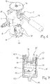
- einen Schnitt durch das Antriebsgehäuse der Spannvorrichtung;
- Fig. 5
- das Antriebsgehäuse in perspektivischer Darstellung;
- Fig. 6
- in perspektivischer Ansicht eine andere Variante der Spannvorrichtung, aufgesetzt auf die Schraubverbindung, sowie ein an die Vorrichtung angesetztes Handwerkzeug zum Nachziehen bzw. Beidrehen der Gewindemutter der Schraubverbindung;
- Fig. 7
- einen Schnitt durch ein gemäß
Fig. 6 verwendetes Kupplungsmodul. - Die Schraubverbindung nach
Fig. 1 umfasst einen Gewindebolzen 2, der sich z. B. aus einem erweiterten Bolzenkopf und einem Schaft- und einem Gewindeabschnitt zusammensetzt, und eine auf den Gewindeabschnitt des Gewindebolzens 2 aufgeschraubte Gewindemutter 3. Die Schraubverbindung verspannt hier zwei Maschinenteile 5, 6 gegeneinander, bei denen es sich z.B. um zwei Flansche handelt. - Neben dem Gewindebolzen 2 und der darauf aufgeschraubten Gewindemutter 3 können weitere Elemente Bestandteil der Schraubverbindung sein, beispielsweise eine weitere Mutter auf der der Gewindemutter 3 abgewandten Seite der zu verspannenden Maschinenteile 5, 6. Auch zusätzliche Unterlegscheiben können Bestandteil der Schraubverbindung sein.
- Mittels einer Spannvorrichtung 11 in der Bauart als hydraulischer Spannzylinder wird die Schraubverbindung durch Aufbringen einer ausschließlich axialen Zugkraft längsgedehnt. Dabei wird durch axialen Zug an dem über die Gewindemutter 3 hinausragenden Gewindeendabschnitt 2A des Gewindebolzens 2 der Gewindebolzen 2 längsgedehnt, wobei sich vor allem der Schaft- und der Gewindeabschnitt des Gewindebolzens 2 dehnt. Die dabei aufgewendete Anzugskraft und/oder der mittels der Hydraulik aufgewendete Anzugsdruck kann unter Einsatz einer Auswerteeinheit automatisch in einem Dokumentationsmodul gespeichert werden, und steht so für spätere Prüfzwecke zur Verfügung.
- Während durch Aktivierung des Spannzylinders für eine gewisse Zeit eine vorgegebene Vorspannkraft auf den Gewindebolzen 2 ausgeübt wird, kann die Gewindemutter 3 durch Drehen angezogen bzw. nachgezogen werden. Dieses sogenannte Beidrehen der Mutter erfolgt von Hand mittels eines Handwerkzeugs 10, z. B. eines Mehrkantschlüssels mit oder ohne integriertem Ratschenmechanismus. Auch das für das Beidrehen der Mutter 3 tatsächlich aufgewendete Anzugsmoment kann automatisch in dem Dokumentationsmodul gespeichert werden.
- Eine zentral in einem Zylindergehäuse 7 der Spannvorrichtung längsbeweglich angeordnete Wechselbuchse 12 ist an einem Ende mit einem Innengewinde 13 versehen. Mit dem Innengewinde 13 wird die Wechselbuchse 12 vor dem Spannprozess auf den über die Mutter 3 hinausragenden Gewindeendabschnitt 2A aufgeschraubt. Dieses Aufschrauben erfolgt ebenfalls mit dem Handwerkzeug 10, wozu die Wechselbuchse 12 an ihrem anderen Ende einen Antriebsmehrkant 14 aufweist, an den sich das Handwerkzeug 10 ansetzen lässt.
- Beim Spannprozess wird die auf den Gewindebolzen 2 aufgeschraubte Wechselbuchse 12 durch Hydraulikdruck unter axialen Zug gesetzt, wodurch sich der Gewindebolzen 2 in seiner Längsrichtung dehnt. Infolge dessen kommt die Unterseite der Mutter 3 von der Unterlage 5A frei. In diesem Zustand lässt sich die Mutter 3 mit relativ wenig Widerstand drehen und bis zu ihrer erneuten, spaltfreien Auflage auf der Unterlage 5A beidrehen. Das Beidrehen erfolgt mittels des Handwerkzeugs 10. Dessen Dreh- oder Schwenkbewegung wird über eine zwischengeschaltete Getriebeanordnung 15 in eine Drehbewegung der Gewindemutter 3 übertragen wird.
- Das unmittelbare Drehen der Mutter 3 erfolgt durch einen in einem Stützrohr 8 gelagerten Mitnehmer 16. Der Mitnehmer 16 ist bei der hier beschriebenen Ausführungsform eine die Mutter 3 umgebende Drehhülse, die an ihrer Innenseite mit Formschlussstrukturen versehen ist und insbesondere mit einem Sechskant, der den an der Mutter 3 angeformten Sechskant formschlüssig umgreift. Angetrieben wird der Mitnehmer bzw. die Drehhülse 16 durch ein als Ritzel ausgebildetes Getriebeelement 17 der Getriebeanordnung 15. Die Getriebeanordnung 15 befindet sich größtenteils in einem Antriebsgehäuse 18, welches als Modul außen an dem Spannzylinder der Spannvorrichtung befestigt ist.
- Umschlossen ist der hydraulische Spannmechanismus von dem druckfesten Zylindergehäuse 7. Dessen starre Fortsetzung nach unten bildet das die Gewindemutter 3 umgebende Stützrohr 8. Das Stützrohr 8 kann einstückig mit dem Zylindergehäuse 7 sein, oder ein gegenüber dem Zylindergehäuse 7 separates, z. B. ein daran angesetztes Bauteil. Das Stützrohr 8 ist an seiner Unterseite offen und stützt sich mit dieser Unterseite auf jener festen Unterlage 5A ab, auf der sich auch die Mutter 3 mit ihrer Unterseite abstützt.
- An dem Zylindergehäuse 7 befindet sich ein Hydraulikanschluss 20, über den ein hydraulischer Arbeitsraum 21 ventilgesteuert mit einer externen Hydraulikversorgung, zum Beispiel einer Hydraulikpumpe, verbunden ist.
- In dem Zylindergehäuse 7 ist, zu der Zylinderinnenwand hin abgedichtet, ein Kolben 25 in Längsrichtung beweglich angeordnet. Durch Einspeisen von hydraulischem Druck in den hydraulischen Arbeitsraum 21 des Spannzylinders hebt der Kolben 25 an. Dies kann beispielsweise entgegen der Kraft einer den Kolben 25 von oben her beaufschlagenden Feder erfolgen, die als Kolbenrückstellfeder dient und bestrebt ist, den Kolben 25 in seiner Grundstellung zu halten, in welcher der hydraulische Arbeitsraum 21 sein Minimum hat.
- Der Kolben 25 umgibt ringförmig die Wechselbuchse 12. Er ist an seinem Innenrand mit einem Absatz oder einer Stufe 27 versehen, die, der Unterlage 5A abgewandt, eine Mitnehmerfläche bildet, an der sich die Wechselbuchse 12 abstützt. Speist die Hydraulikpumpe Druckfluid in den Arbeitsraum 21, so hebt der Kolben 25 an und nimmt die Wechselbuchse 12 axial mit. Es kommt zu dem Längsdehnen des Gewindebolzens 2.
- Die Wechselbuchse 12 ist an ihrem bolzenseitigen Ende mit dem Innengewinde 13 zum Aufschrauben auf den Gewindebolzen 2 versehen. An ihrem anderen Ende ist die Wechselbuchse 12 mit dem Antriebsmehrkant 14 versehen, an den sich das Handwerkzeug 10 ansetzen lässt, um bei der Vorbereitung des Spannprozesses mit dem Handwerkzeug 10 die Wechselbuchse 12 zu drehen und auf den Gewindebolzen 2 aufzuschrauben.
- Zum Drehen der Drehhülse 16 weist das Stützrohr 8 auf jenem Umfangsbereich, auf dem sich das Antriebsgehäuse 18 mit der Getriebeanordnung 15 befindet, eine Öffnung 28 auf. Durch die Öffnung 28 hindurch wird daher die Drehhülse 16 angetrieben. Die Getriebeanordnung 15 bildet daher zusammen mit der Drehhülse 16 eine Einrichtung zum Beidrehen der Mutter 3. Die Mutter 3 kann natürlich nur sinnvoll beigedreht werden, solange der Kolben 25 unter Hydraulikdruck steht.
- Die für das Beidrehen benötigte Kraft wird, z. B. durch Hin- und Herbewegen des als Ratschenschlüssel ausgebildeten Handwerkzeugs 10, solange aufgebracht, bis eine Drehmomentbegrenzung jede weitere Steigerung ausschließt. Dazu ist ein Bestandteil der Getriebeanordnung 15 eine drehmomentabhängig arbeitende Kupplung 30 in der Bauart einer Überlastkupplung.
- Anhand der
Figuren 3, 4 und 5 werden Einzelheiten der Getriebeanordnung 15 bei einer ersten Ausführungsform beschrieben. - In dem Antriebsgehäuse 18, welches außen an dem Stützrohr 8 befestigt ist, sind auf zwei zueinander parallelen Drehachsen das Getriebeelement 17 und ein weiteres Getriebeelement 37 gelagert. Die Getriebeelemente 17, 37 sind miteinander kämmende Zahnritzel. Das Getriebeelement 17 kämmt zudem mit einer Verzahnung, welche außen an der Drehhülse 16 ausgebildet ist. Hierzu ragt das Getriebeelement 17 in die Öffnung 28 (
Fig. 2 ), mit der das Stützrohr 8 auf dieser Umfangsposition versehen ist. - Das Getriebeelement 37 ist mehrteilig ausgebildet und weist unter anderem eine Werkzeugfläche 38 auf, an die sich das Handwerkzeug 10 mit seiner entsprechend geformten Werkzeugfläche ansetzen lässt.
- Der Antriebsweg innerhalb der Getriebeanordnung 15 ist dergestalt, dass mittels des an die Werkzeugfläche 38 angesetzten Handwerkzeugs 10 das Getriebeelement 37 in Drehung versetzt wird, und diese Bewegung über das zwischengeschaltete Getriebeelement 17 auf die in dem Stützrohr 8 gelagerte Drehhülse16 übertragen wird. Durch das Getriebeelement 17 als Zwischenritzel ist sichergestellt, dass die Drehrichtung an der Werkzeugfläche 38 gleichsinnig ist zu der Drehrichtung der Gewindemutter 3 beim Beidrehen.
- Bei der Ausführungsform nach den
Figuren 3, 4 und 5 ist die drehmomentabhängig arbeitende Kupplung 30 in das Getriebeelement 37 integriert, welches zu diesem Zweck mehrteilig ist. Bestandteile des mehrteiligen Getriebeelements 37 sind eine an ihrem Umfang mit einer Verzahnung versehene erste Scheibe 31, eine mit der ersten Scheibe 31 drehfest gekoppelte zweite Scheibe 32 und eine zwischen den Scheiben 31, 32 angeordnete, dritte Scheibe 33. - Die drei Scheiben 31, 32, 33 mit ihren flach gegeneinander anliegenden Reibflächen sind die Kupplungspartner der Überlastkupplung. Die mittlere Scheibe 33 bildet mit ihren beiden Reibflächen den ersten Kupplungspartner. Ferner ist die gegen die mittlere Scheibe 33 anliegende Flachseite der Scheibe 31 eine Reibfläche, und ebenso ist die gegen die mittlere Scheibe 33 anliegende Flachseite der Scheibe 32 eine Reibfläche. Daher bilden die zueinander drehfesten Scheiben 31, 32 gemeinsam den zweiten Kupplungspartner, welcher über das zwischengeschaltete Getriebeelement 17 in einer mittelbaren Drehverbindung mit der Drehhülse 16 steht.
- Gemäß
Fig. 4 ist die Scheibe 31 nicht nur zweiter Kupplungspartner, sondern sie ist mit ihrer Verzahnung zugleich das Ritzel, welches über das zwischengeschaltete Getriebeelement 17 die Drehverbindung zu der Drehhülse 16 herstellt. - Die mittlere Scheibe 33 der Kupplung ist einstückiger Bestandteil eines in dem Antriebsgehäuse 18 drehbar gelagerten Antriebselements 35. An dem Antriebselement 35 ist, hier außerhalb des Antriebsgehäuses 18, jene Werkzeugfläche 38 ausgebildet, an die sich das Handwerkzeug 10 ansetzen lässt.
- Schrauben 36 mit Schraubenachse parallel zur Kupplungsdrehachse verbinden die äußeren Scheiben 31, 32 miteinander, ohne die mittlere Scheibe 33 zu berühren. Durch Anziehen der Schrauben 36 werden die Scheiben 31, 32 stärker zueinander gezogen, wodurch sich ihr Druck auf die mittlere Scheibe 33 erhöht. Dieser Druck und damit die Reibung zwischen den Scheiben 31, 32, 33 bestimmt das von der drehmomentabhängig arbeitenden Kupplung 30 maximal, d.h. bis zum Durchrutschen übertragbare Drehmoment.
- In der Praxis ist eine Veränderung des Drucks und damit der Reibung zwischen den Kupplungspartnern 31, 32, 33 der Überlastkupplung eher selten erforderlich, oder sogar unerwünscht. Daher sind die Schrauben 36 für eine Änderung der Kupplungskraft nur zugänglich, wenn zunächst ein Deckel 39 entfernt wird, welcher Bestandteil des Antriebsgehäuses 18 ist. Der Deckel 39 seinerseits ist durch Schrauben 40 gesichert.
- Anhand der
Figuren 6 und 7 wird nachfolgend eine zweite Ausführungsform der Getriebeanordnung 15 beschrieben. - Bei dieser Ausführungsform sind das mit der Werkzeugfläche 38 für das Ansetzen des Handwerkzeugs 10 versehene Antriebselement 35 und die drehmomentabhängig arbeitende Kupplung 30 Bestandteile eines Kupplungsmoduls 41. Das Kupplungsmodul 41 ist lösbar an das Antriebsgehäuse 18 angesetzt. Die Einzelteile der Getriebeanordnung 15 befinden sich teilweise in dem an dem Stützrohr 8 befestigten Antriebsgehäuse 18, und teilweise in dem separaten Kupplungsmodul 41.
- Bestandteil des Kupplungsmoduls 41 ist ein ein- oder mehrteiliges Gehäuse 45. Das Gehäuse 45 ist, dem darin drehbaren Antriebselement 35 abgewandt, mit einem starr an dem Gehäuse 45 ausgebildeten Formschlusselement 42 versehen ist, z.B. einem Vierkant. Ist gemäß
Fig. 6 das Kupplungsmodul 41 an das Antriebsgehäuse 18 angesetzt, greift das Formschlusselement 42 in eine entsprechende Gegenstruktur an dem als Ritzel ausgebildeten Getriebeelement 37 (Fig. 4 ). - Die drehmomentabhängig arbeitende Kupplung 30 arbeitet bei der zweiten Ausführungsform mit zwei konischen Reibflächen. Das mit der Werkzeugfläche 38 versehene Antriebselement 35 weist einen ersten Konus auf. Dieser bildet den ersten Kupplungspartner 43 der Überlastkupplung. Ein korrespondierender Konus an dem ein- oder mehrteiligen Gehäuse 45 bildet den zweiten Kupplungspartner 44, welcher über die zwischengeschalteten Getriebeelemente 37, 17 in einer mittelbaren Drehverbindung mit der Drehhülse 16 steht.
- Das übertragbare Drehmoment ist einstellbar, wozu sich ein Federelement 48 mit seinem ersten Ende gegen das Antriebselement 35, und mit seinem zweiten Ende gegen einen Federsitz an dem Gehäuse 45 abstützt. Um ein Verwinden des Federelements 48 zu vermeiden, stützt sich das Federelement 48 gehäuseseitig nicht unmittelbar gegen das Gehäuse 45 ab, sondern gegen ein Axiallager 49, welches seinerseits in dem Gehäuse 45 abgestützt ist.
- Der Abstand der Federsitze und damit die Länge des Federelements 48 ist einstellbar. Zu diesem Zweck ist das Gehäuse 45 zweigeteilt und setzt sich aus miteinander über ein Gewinde 47 verschraubten Gehäuseteilen 45A, 45B zusammen.
- Bei beiden beschriebenen Ausführungsformen kann ein Getriebeelement der Getriebeanordnung 15 mit einem Drehwinkelsensor versehen sein. Dieser erfasst einen Drehwinkel, welcher im Laufe des Anziehens der Mutter 3 bis zum Erreichen des Drehmomentmaximalwerts insgesamt zurückgelegt wird. Der erfasste Drehwinkel kann entweder der Drehwinkel der Drehhülse 16 und damit der Mutter 3 selbst sein, oder ein Drehwinkel, den eines der sich drehenden Getriebeelemente der Getriebeanordnung 15 ausführt. Auch der so erfasste Winkelwert kann in dem Dokumentationsmodul gespeichert werden.
-
- 2
- Gewindebolzen
- 2A
- Gewindeendabschnitt
- 3
- Mutter, Gewindemutter
- 5
- Maschinenteil
- 5A
- Unterlage
- 6
- Maschinenteil
- 7
- Zylindergehäuse
- 8
- Stützrohr
- 10
- Handwerkzeug
- 11
- Spannvorrichtung
- 12
- Wechselbuchse
- 13
- Innengewinde
- 14
- Antriebsmehrkant
- 15
- Getriebeanordnung
- 16
- Mitnehmer, Drehhülse
- 17
- Getriebeelement
- 18
- Antriebsgehäuse
- 20
- Hydraulikanschluss
- 21
- Arbeitsraum
- 25
- Kolben
- 27
- Stufe
- 28
- Öffnung
- 30
- drehmomentabhängig arbeitende Kupplung
- 31
- Scheibe, zweiter Kupplungspartner
- 32
- Scheibe, zweiter Kupplungspartner
- 33
- Scheibe, erster Kupplungspartner
- 35
- Antriebselement
- 36
- Schraube
- 37
- Getriebeelement
- 38
- Werkzeugfläche
- 39
- Deckel
- 40
- Schraube
- 41
- Kupplungsmodul
- 42
- Formschlusselement
- 43
- Konus, erster Kupplungspartner
- 44
- Konus, zweiter Kupplungspartner
- 45
- Gehäuse
- 45A
- Gehäuseteil
- 45B
- Gehäuseteil
- 47
- Gewinde
- 48
- Federelement
- 49
- Axiallager
Claims (12)
- Spannvorrichtung für eine Schraubverbindung bestehend aus einem Gewindebolzen und einer Gewindemutter, mit einem die Gewindemutter umgebenden Stützrohr (8), einem Zylindergehäuse (7) in Verlängerung des Stützrohrs (8), einem in dem Zylindergehäuse (7) mittels Hydraulikdruck bewegbaren Kolben (25), einer durch den Kolben (25) axial mitnehmbaren Wechselbuchse (12), welche mit einem Innengewinde (13) zum Verschrauben der Wechselbuchse (12) mit dem Gewindebolzen versehen ist, einem innerhalb des Stützrohrs (8) angeordneten, mit der Gewindemutter kraft- oder formschlüssig verbindbaren Mitnehmer (16), und einer Getriebeanordnung (15) zwischen einem außerhalb des Stützrohrs (8) drehgelagerten Antriebselement (35), welches mit einer Werkzeugfläche (38) zum Ansetzen eines Handwerkzeugs (10) versehen ist, und dem Mitnehmer (16), dadurch gekennzeichnet, dass Bestandteil der Getriebeanordnung (15) eine drehmomentabhängig arbeitende Kupplung (30) ist, wobei Bestandteile der drehmomentabhängig arbeitenden Kupplung (30) druckbelastet gegeneinander abgestützte Kupplungspartner sind, dass ein erster Kupplungspartner (33, 43) in einer mittel- oder unmittelbaren Drehverbindung mit dem Antriebselement (35), und ein zweiter Kupplungspartner (31, 32, 44) in einer mittel- oder unmittelbaren Drehverbindung mit dem Mitnehmer (16) dreht.
- Spannvorrichtung nach Anspruch 1, dadurch gekennzeichnet, dass die drehmomentabhängig arbeitende Kupplung (30) eine Überlastkupplung ist, vorzugsweise eine Rutschkupplung.
- Spannvorrichtung nach Anspruch 1 oder 2, gekennzeichnet durch Mittel (36, 48) zum Einstellen der Größe der Druckbelastung zwischen den Kupplungspartnern (33, 43, 31, 32, 44).
- Spannvorrichtung nach einem der vorangehenden Ansprüche, dadurch gekennzeichnet, dass die Kupplungspartner (43, 44) durch mindestens ein Federelement (48) druckbelastet gegeneinander abgestützt sind.
- Spannvorrichtung nach Anspruch 4, dadurch gekennzeichnet, dass das Federelement (48) mit seinem ersten Ende gegen einen ersten Federsitz und mit seinem zweiten Ende gegen einen zweiten Federsitz abgestützt ist, und dass der Abstand der Federsitze zueinander einstellbar ist.
- Spannvorrichtung nach einem der vorangehenden Ansprüche, dadurch gekennzeichnet, dass an den Kupplungspartnern jeweils flächig aneinander abgestützte Reibflächen ausgebildet sind.
- Spannvorrichtung nach einem der vorangehenden Ansprüche, gekennzeichnet durch ein zumindest Teile der Getriebeanordnung (15) umschließendes Antriebsgehäuse (18), welches außen auf einem Umfangsbereich des Stützrohrs (8) befestigt ist, auf dem das Stützrohr (8) mit einer Öffnung (28) versehen ist, wobei sich ein Getriebeelement (17) der Getriebeanordnung (15) in die Öffnung (28) hinein erstreckt.
- Spannvorrichtung nach Anspruch 7, dadurch gekennzeichnet, dass das Getriebeelement (17) im Eingriff mit dem Mitnehmer (16) steht.
- Spannvorrichtung nach Anspruch 7 oder 8, dadurch gekennzeichnet, dass das Antriebselement (35) und die drehmomentabhängig arbeitende Kupplung (30) in dem Antriebsgehäuse (18) angeordnet sind.
- Spannvorrichtung nach Anspruch 7 oder 8, dadurch gekennzeichnet, dass das Antriebselement (35) und die drehmomentabhängig arbeitende Kupplung (30) Bestandteile eines an das Antriebsgehäuse (18) lösbar angesetzten Kupplungsmoduls (41) sind.
- Spannvorrichtung nach Anspruch 10, dadurch gekennzeichnet, dass Bestandteil des Kupplungsmoduls (41) außerdem ein Formschlusselement (42) ist, welches in lösbarem Eingriff mit einem in dem Antriebsgehäuse (18) gelagerten Getriebeelement (37) steht, wobei die drehmomentabhängig arbeitende Kupplung (30) zwischen dem Antriebselement (35) und dem Formschlusselement (42) angeordnet ist.
- Spannvorrichtung nach einem der vorangehenden Ansprüche, dadurch gekennzeichnet, dass der Mitnehmer (16) eine drehbar in dem Stützrohr (8) angeordnete Drehhülse ist, die an ihrer Innenseite mit Formschlussstrukturen zur Verbindung mit der Gewindemutter versehen ist.
Applications Claiming Priority (1)
| Application Number | Priority Date | Filing Date | Title |
|---|---|---|---|
| DE102019111185.4A DE102019111185A1 (de) | 2019-04-30 | 2019-04-30 | Spannvorrichtung für eine Schraubverbindung |
Publications (2)
| Publication Number | Publication Date |
|---|---|
| EP3733349A1 EP3733349A1 (de) | 2020-11-04 |
| EP3733349B1 true EP3733349B1 (de) | 2022-07-06 |
Family
ID=70154261
Family Applications (1)
| Application Number | Title | Priority Date | Filing Date |
|---|---|---|---|
| EP20167492.6A Active EP3733349B1 (de) | 2019-04-30 | 2020-04-01 | Spannvorrichtung für eine schraubverbindung |
Country Status (5)
| Country | Link |
|---|---|
| US (1) | US11466711B2 (de) |
| EP (1) | EP3733349B1 (de) |
| JP (1) | JP7554576B2 (de) |
| DE (1) | DE102019111185A1 (de) |
| ES (1) | ES2924980T3 (de) |
Families Citing this family (8)
| Publication number | Priority date | Publication date | Assignee | Title |
|---|---|---|---|---|
| ES2775069B2 (es) * | 2017-12-27 | 2021-06-23 | Nabrawind Tech Sl | Sistema de control del pretensado de pernos |
| DE102021102230A1 (de) * | 2021-02-01 | 2022-08-04 | Frank Hohmann | Werkzeugsicherung gegen Schraubenbruch |
| CN113798833B (zh) * | 2021-08-13 | 2022-08-19 | 苏州浪潮智能科技有限公司 | 一种带弹簧螺丝的pcba散热片组装治具 |
| CN113829036B (zh) * | 2021-09-17 | 2022-12-02 | 宁波麦吉克自控设备有限公司 | 一种调压电磁阀的组装设备 |
| CN115070202B (zh) * | 2022-05-31 | 2023-08-29 | 扬州屹丰汽车部件有限公司 | 一种激光切割机的物料导向装置及其使用方法 |
| CN116734054B (zh) * | 2023-06-12 | 2026-06-26 | 烟台中集来福士海洋工程有限公司 | 锁紧设备、立管支撑装置以及立管的安装连接方法 |
| CN119609641A (zh) * | 2024-11-28 | 2025-03-14 | 北京新风航天装备有限公司 | 一种圆螺母自动拧紧方法 |
| CN119703723B (zh) * | 2024-12-23 | 2025-10-10 | 广州丰桥智能装备有限公司 | 一种新能源汽车刹车盘增紧设备及车辆生产线 |
Family Cites Families (16)
| Publication number | Priority date | Publication date | Assignee | Title |
|---|---|---|---|---|
| DE2258859A1 (de) * | 1972-12-01 | 1974-06-12 | Masch Und Bohrgeraete Fabrik | Hydraulische spannvorrichtung |
| JPS6296795A (ja) * | 1985-10-24 | 1987-05-06 | Japan Atom Power Co Ltd:The | インタナルポンプのモ−タ部取付ナツト着脱装置 |
| JP2851652B2 (ja) * | 1989-10-11 | 1999-01-27 | 東洋エンジニアリング株式会社 | フランジボルトナットの締緩装置 |
| US5075950A (en) * | 1990-06-28 | 1991-12-31 | Steinbock Rolf H | Method for loosening jack bolts |
| JPH08142Y2 (ja) * | 1991-03-26 | 1996-01-10 | 株式会社マイティエンジニアリング | トルク制限型の回転力伝達部材 |
| DE4313778A1 (de) * | 1993-04-27 | 1994-11-03 | Westfalia Becorit Ind Tech | Schraubenspannvorrichtung |
| JP3187664B2 (ja) * | 1994-09-07 | 2001-07-11 | 株式会社東日製作所 | インパクトレンチリミッタ |
| JPH11198056A (ja) * | 1998-01-12 | 1999-07-27 | Mitsubishi Heavy Ind Ltd | ボルト着脱装置 |
| DE102004043146B3 (de) * | 2004-09-03 | 2005-11-24 | Hohmann, Jörg | Hydraulische Schraubenspannvorrichtung |
| DE102004043145B3 (de) * | 2004-09-03 | 2006-05-18 | Hohmann, Jörg | Hydraulische Schraubenspannvorrichtung |
| DE102007005284A1 (de) * | 2007-02-02 | 2008-08-07 | Wagner, Paul-Heinz | Verfahren zum Zusammenfügen von Bauteilen durch Spannbolzen |
| US20110271798A1 (en) * | 2008-11-14 | 2011-11-10 | Wagner Vermogensverwaltungs- GMBH & Co.KG | Screw tensioning device |
| DE102013107096A1 (de) * | 2013-07-05 | 2015-01-08 | Ith Gmbh & Co. Kg | Spannvorrichtung zum Dehnen eines Gewindebolzens |
| EP2871027B1 (de) * | 2013-11-11 | 2016-10-05 | HILTI Aktiengesellschaft | Bolzenspannwerkzeug |
| DE102017119676A1 (de) * | 2017-08-28 | 2019-02-28 | Frank Hohmann | Verfahren zum dokumentierten Anziehen oder Nachziehen einer Schraubverbindung |
| GB2580115B (en) * | 2018-12-21 | 2021-08-25 | Caterpillar Energy Solutions Gmbh | Device for tensioning and tightening a screw |
-
2019
- 2019-04-30 DE DE102019111185.4A patent/DE102019111185A1/de not_active Withdrawn
-
2020
- 2020-04-01 ES ES20167492T patent/ES2924980T3/es active Active
- 2020-04-01 EP EP20167492.6A patent/EP3733349B1/de active Active
- 2020-04-22 US US16/855,132 patent/US11466711B2/en active Active
- 2020-04-28 JP JP2020078950A patent/JP7554576B2/ja active Active
Also Published As
| Publication number | Publication date |
|---|---|
| US20200347859A1 (en) | 2020-11-05 |
| US11466711B2 (en) | 2022-10-11 |
| DE102019111185A1 (de) | 2020-11-05 |
| JP2020183030A (ja) | 2020-11-12 |
| JP7554576B2 (ja) | 2024-09-20 |
| EP3733349A1 (de) | 2020-11-04 |
| ES2924980T3 (es) | 2022-10-13 |
Similar Documents
| Publication | Publication Date | Title |
|---|---|---|
| EP3733349A1 (de) | Spannvorrichtung für eine schraubverbindung | |
| EP3708753B1 (de) | Deckelbeschlag zum schwenkbaren befestigen eines deckels an einen möbelkorpus | |
| DE102011055438B4 (de) | Verstellvorrichtung für einen Kraftfahrzeugsitz | |
| DE102007020542A1 (de) | Werkzeug mit Drehmomentverstärkung | |
| EP2837467A1 (de) | Spanneinheit, insbesondere zur Verwendung in einem Bearbeitungszentrum bzw. einem Dreh- bzw. Fräszentrum | |
| EP0747606A1 (de) | Verschluss zur Sicherung einer Kupplungshülse | |
| EP2821182B1 (de) | Spannvorrichtung zum Dehnen eines Gewindebolzens | |
| EP0577981B1 (de) | Handstückkopf für ein ärztliches oder zahnärztliches Handstück mit einem hin- und herbewegbaren Behandlungswerkzeug | |
| WO2012122971A1 (de) | Kraftschrauber-überlastsicherung | |
| DE1478904A1 (de) | Drehschlagschrauber | |
| EP3272207A1 (de) | Arbeitsgerät mit über ein schwenkgelenk verbundenen teilgehäusen | |
| DE102008048076A1 (de) | Schraubwerkzeug | |
| DE2805881C2 (de) | Spanndorn für die koaxiale Außenbearbeitung von Werkstücken mit Innenverzahnung | |
| DE4143218C2 (de) | Vorrichtung zur Verbindung von Schraubendreher-Einsätzen | |
| EP3147079A1 (de) | Vorrichtung zur drehmomentbegrenzung | |
| EP3372343B1 (de) | Anordnung aus einem reaktionsmomente ableitenden stützarm und einem drehschrauber | |
| DE3528757A1 (de) | Rutschkupplung mit einstellbarem ansprechdrehmoment | |
| EP1517050A1 (de) | Selbstsicherndes Schraubelement | |
| EP3909903A1 (de) | Anschlagpunkt | |
| DE3216696C2 (de) | ||
| EP4519047A1 (de) | Hohlkolbenzylinder | |
| DE102007023807B4 (de) | Umschaltmittel für Schrauber mit zwei Abtrieben | |
| DE29618817U1 (de) | Drehmomentverstärkender Schrauber | |
| EP3665001B1 (de) | Presse mit sensor zum messen der presskraft | |
| DE19819251B4 (de) | Handnietgerät zum Setzen von Blindnietmuttern |
Legal Events
| Date | Code | Title | Description |
|---|---|---|---|
| PUAI | Public reference made under article 153(3) epc to a published international application that has entered the european phase |
Free format text: ORIGINAL CODE: 0009012 |
|
| STAA | Information on the status of an ep patent application or granted ep patent |
Free format text: STATUS: THE APPLICATION HAS BEEN PUBLISHED |
|
| AK | Designated contracting states |
Kind code of ref document: A1 Designated state(s): AL AT BE BG CH CY CZ DE DK EE ES FI FR GB GR HR HU IE IS IT LI LT LU LV MC MK MT NL NO PL PT RO RS SE SI SK SM TR |
|
| AX | Request for extension of the european patent |
Extension state: BA ME |
|
| STAA | Information on the status of an ep patent application or granted ep patent |
Free format text: STATUS: REQUEST FOR EXAMINATION WAS MADE |
|
| 17P | Request for examination filed |
Effective date: 20210311 |
|
| RBV | Designated contracting states (corrected) |
Designated state(s): AL AT BE BG CH CY CZ DE DK EE ES FI FR GB GR HR HU IE IS IT LI LT LU LV MC MK MT NL NO PL PT RO RS SE SI SK SM TR |
|
| GRAP | Despatch of communication of intention to grant a patent |
Free format text: ORIGINAL CODE: EPIDOSNIGR1 |
|
| STAA | Information on the status of an ep patent application or granted ep patent |
Free format text: STATUS: GRANT OF PATENT IS INTENDED |
|
| INTG | Intention to grant announced |
Effective date: 20220408 |
|
| GRAS | Grant fee paid |
Free format text: ORIGINAL CODE: EPIDOSNIGR3 |
|
| GRAA | (expected) grant |
Free format text: ORIGINAL CODE: 0009210 |
|
| STAA | Information on the status of an ep patent application or granted ep patent |
Free format text: STATUS: THE PATENT HAS BEEN GRANTED |
|
| AK | Designated contracting states |
Kind code of ref document: B1 Designated state(s): AL AT BE BG CH CY CZ DE DK EE ES FI FR GB GR HR HU IE IS IT LI LT LU LV MC MK MT NL NO PL PT RO RS SE SI SK SM TR |
|
| REG | Reference to a national code |
Ref country code: AT Ref legal event code: REF Ref document number: 1502539 Country of ref document: AT Kind code of ref document: T Effective date: 20220715 Ref country code: CH Ref legal event code: EP |
|
| REG | Reference to a national code |
Ref country code: DE Ref legal event code: R096 Ref document number: 502020001319 Country of ref document: DE |
|
| REG | Reference to a national code |
Ref country code: IE Ref legal event code: FG4D Free format text: LANGUAGE OF EP DOCUMENT: GERMAN |
|
| REG | Reference to a national code |
Ref country code: ES Ref legal event code: FG2A Ref document number: 2924980 Country of ref document: ES Kind code of ref document: T3 Effective date: 20221013 |
|
| REG | Reference to a national code |
Ref country code: LT Ref legal event code: MG9D |
|
| REG | Reference to a national code |
Ref country code: NL Ref legal event code: MP Effective date: 20220706 |
|
| PG25 | Lapsed in a contracting state [announced via postgrant information from national office to epo] |
Ref country code: SE Free format text: LAPSE BECAUSE OF FAILURE TO SUBMIT A TRANSLATION OF THE DESCRIPTION OR TO PAY THE FEE WITHIN THE PRESCRIBED TIME-LIMIT Effective date: 20220706 Ref country code: RS Free format text: LAPSE BECAUSE OF FAILURE TO SUBMIT A TRANSLATION OF THE DESCRIPTION OR TO PAY THE FEE WITHIN THE PRESCRIBED TIME-LIMIT Effective date: 20220706 Ref country code: PT Free format text: LAPSE BECAUSE OF FAILURE TO SUBMIT A TRANSLATION OF THE DESCRIPTION OR TO PAY THE FEE WITHIN THE PRESCRIBED TIME-LIMIT Effective date: 20221107 Ref country code: NO Free format text: LAPSE BECAUSE OF FAILURE TO SUBMIT A TRANSLATION OF THE DESCRIPTION OR TO PAY THE FEE WITHIN THE PRESCRIBED TIME-LIMIT Effective date: 20221006 Ref country code: NL Free format text: LAPSE BECAUSE OF FAILURE TO SUBMIT A TRANSLATION OF THE DESCRIPTION OR TO PAY THE FEE WITHIN THE PRESCRIBED TIME-LIMIT Effective date: 20220706 Ref country code: LV Free format text: LAPSE BECAUSE OF FAILURE TO SUBMIT A TRANSLATION OF THE DESCRIPTION OR TO PAY THE FEE WITHIN THE PRESCRIBED TIME-LIMIT Effective date: 20220706 Ref country code: LT Free format text: LAPSE BECAUSE OF FAILURE TO SUBMIT A TRANSLATION OF THE DESCRIPTION OR TO PAY THE FEE WITHIN THE PRESCRIBED TIME-LIMIT Effective date: 20220706 Ref country code: FI Free format text: LAPSE BECAUSE OF FAILURE TO SUBMIT A TRANSLATION OF THE DESCRIPTION OR TO PAY THE FEE WITHIN THE PRESCRIBED TIME-LIMIT Effective date: 20220706 |
|
| PG25 | Lapsed in a contracting state [announced via postgrant information from national office to epo] |
Ref country code: PL Free format text: LAPSE BECAUSE OF FAILURE TO SUBMIT A TRANSLATION OF THE DESCRIPTION OR TO PAY THE FEE WITHIN THE PRESCRIBED TIME-LIMIT Effective date: 20220706 Ref country code: IS Free format text: LAPSE BECAUSE OF FAILURE TO SUBMIT A TRANSLATION OF THE DESCRIPTION OR TO PAY THE FEE WITHIN THE PRESCRIBED TIME-LIMIT Effective date: 20221106 Ref country code: HR Free format text: LAPSE BECAUSE OF FAILURE TO SUBMIT A TRANSLATION OF THE DESCRIPTION OR TO PAY THE FEE WITHIN THE PRESCRIBED TIME-LIMIT Effective date: 20220706 |
|
| REG | Reference to a national code |
Ref country code: DE Ref legal event code: R097 Ref document number: 502020001319 Country of ref document: DE |
|
| PG25 | Lapsed in a contracting state [announced via postgrant information from national office to epo] |
Ref country code: SM Free format text: LAPSE BECAUSE OF FAILURE TO SUBMIT A TRANSLATION OF THE DESCRIPTION OR TO PAY THE FEE WITHIN THE PRESCRIBED TIME-LIMIT Effective date: 20220706 Ref country code: RO Free format text: LAPSE BECAUSE OF FAILURE TO SUBMIT A TRANSLATION OF THE DESCRIPTION OR TO PAY THE FEE WITHIN THE PRESCRIBED TIME-LIMIT Effective date: 20220706 Ref country code: DK Free format text: LAPSE BECAUSE OF FAILURE TO SUBMIT A TRANSLATION OF THE DESCRIPTION OR TO PAY THE FEE WITHIN THE PRESCRIBED TIME-LIMIT Effective date: 20220706 Ref country code: CZ Free format text: LAPSE BECAUSE OF FAILURE TO SUBMIT A TRANSLATION OF THE DESCRIPTION OR TO PAY THE FEE WITHIN THE PRESCRIBED TIME-LIMIT Effective date: 20220706 |
|
| PLBE | No opposition filed within time limit |
Free format text: ORIGINAL CODE: 0009261 |
|
| STAA | Information on the status of an ep patent application or granted ep patent |
Free format text: STATUS: NO OPPOSITION FILED WITHIN TIME LIMIT |
|
| PG25 | Lapsed in a contracting state [announced via postgrant information from national office to epo] |
Ref country code: SK Free format text: LAPSE BECAUSE OF FAILURE TO SUBMIT A TRANSLATION OF THE DESCRIPTION OR TO PAY THE FEE WITHIN THE PRESCRIBED TIME-LIMIT Effective date: 20220706 Ref country code: EE Free format text: LAPSE BECAUSE OF FAILURE TO SUBMIT A TRANSLATION OF THE DESCRIPTION OR TO PAY THE FEE WITHIN THE PRESCRIBED TIME-LIMIT Effective date: 20220706 |
|
| 26N | No opposition filed |
Effective date: 20230411 |
|
| PG25 | Lapsed in a contracting state [announced via postgrant information from national office to epo] |
Ref country code: AL Free format text: LAPSE BECAUSE OF FAILURE TO SUBMIT A TRANSLATION OF THE DESCRIPTION OR TO PAY THE FEE WITHIN THE PRESCRIBED TIME-LIMIT Effective date: 20220706 |
|
| P01 | Opt-out of the competence of the unified patent court (upc) registered |
Effective date: 20230530 |
|
| PG25 | Lapsed in a contracting state [announced via postgrant information from national office to epo] |
Ref country code: SI Free format text: LAPSE BECAUSE OF FAILURE TO SUBMIT A TRANSLATION OF THE DESCRIPTION OR TO PAY THE FEE WITHIN THE PRESCRIBED TIME-LIMIT Effective date: 20220706 |
|
| REG | Reference to a national code |
Ref country code: CH Ref legal event code: PL |
|
| PG25 | Lapsed in a contracting state [announced via postgrant information from national office to epo] |
Ref country code: LU Free format text: LAPSE BECAUSE OF NON-PAYMENT OF DUE FEES Effective date: 20230401 |
|
| REG | Reference to a national code |
Ref country code: BE Ref legal event code: MM Effective date: 20230430 |
|
| PG25 | Lapsed in a contracting state [announced via postgrant information from national office to epo] |
Ref country code: MC Free format text: LAPSE BECAUSE OF FAILURE TO SUBMIT A TRANSLATION OF THE DESCRIPTION OR TO PAY THE FEE WITHIN THE PRESCRIBED TIME-LIMIT Effective date: 20220706 |
|
| PG25 | Lapsed in a contracting state [announced via postgrant information from national office to epo] |
Ref country code: MC Free format text: LAPSE BECAUSE OF FAILURE TO SUBMIT A TRANSLATION OF THE DESCRIPTION OR TO PAY THE FEE WITHIN THE PRESCRIBED TIME-LIMIT Effective date: 20220706 Ref country code: LI Free format text: LAPSE BECAUSE OF NON-PAYMENT OF DUE FEES Effective date: 20230430 Ref country code: IT Free format text: LAPSE BECAUSE OF FAILURE TO SUBMIT A TRANSLATION OF THE DESCRIPTION OR TO PAY THE FEE WITHIN THE PRESCRIBED TIME-LIMIT Effective date: 20220706 Ref country code: CH Free format text: LAPSE BECAUSE OF NON-PAYMENT OF DUE FEES Effective date: 20230430 |
|
| REG | Reference to a national code |
Ref country code: IE Ref legal event code: MM4A |
|
| PG25 | Lapsed in a contracting state [announced via postgrant information from national office to epo] |
Ref country code: BE Free format text: LAPSE BECAUSE OF NON-PAYMENT OF DUE FEES Effective date: 20230430 |
|
| PG25 | Lapsed in a contracting state [announced via postgrant information from national office to epo] |
Ref country code: IE Free format text: LAPSE BECAUSE OF NON-PAYMENT OF DUE FEES Effective date: 20230401 |
|
| PG25 | Lapsed in a contracting state [announced via postgrant information from national office to epo] |
Ref country code: IE Free format text: LAPSE BECAUSE OF NON-PAYMENT OF DUE FEES Effective date: 20230401 |
|
| PG25 | Lapsed in a contracting state [announced via postgrant information from national office to epo] |
Ref country code: BG Free format text: LAPSE BECAUSE OF FAILURE TO SUBMIT A TRANSLATION OF THE DESCRIPTION OR TO PAY THE FEE WITHIN THE PRESCRIBED TIME-LIMIT Effective date: 20220706 |
|
| PG25 | Lapsed in a contracting state [announced via postgrant information from national office to epo] |
Ref country code: BG Free format text: LAPSE BECAUSE OF FAILURE TO SUBMIT A TRANSLATION OF THE DESCRIPTION OR TO PAY THE FEE WITHIN THE PRESCRIBED TIME-LIMIT Effective date: 20220706 |
|
| PGFP | Annual fee paid to national office [announced via postgrant information from national office to epo] |
Ref country code: AT Payment date: 20250721 Year of fee payment: 5 |
|
| PG25 | Lapsed in a contracting state [announced via postgrant information from national office to epo] |
Ref country code: CY Free format text: LAPSE BECAUSE OF FAILURE TO SUBMIT A TRANSLATION OF THE DESCRIPTION OR TO PAY THE FEE WITHIN THE PRESCRIBED TIME-LIMIT; INVALID AB INITIO Effective date: 20200401 |
|
| PG25 | Lapsed in a contracting state [announced via postgrant information from national office to epo] |
Ref country code: HU Free format text: LAPSE BECAUSE OF FAILURE TO SUBMIT A TRANSLATION OF THE DESCRIPTION OR TO PAY THE FEE WITHIN THE PRESCRIBED TIME-LIMIT; INVALID AB INITIO Effective date: 20200401 |
|
| PG25 | Lapsed in a contracting state [announced via postgrant information from national office to epo] |
Ref country code: GR Free format text: LAPSE BECAUSE OF FAILURE TO SUBMIT A TRANSLATION OF THE DESCRIPTION OR TO PAY THE FEE WITHIN THE PRESCRIBED TIME-LIMIT; INVALID AB INITIO Effective date: 20200401 |
|
| PG25 | Lapsed in a contracting state [announced via postgrant information from national office to epo] |
Ref country code: TR Free format text: LAPSE BECAUSE OF FAILURE TO SUBMIT A TRANSLATION OF THE DESCRIPTION OR TO PAY THE FEE WITHIN THE PRESCRIBED TIME-LIMIT Effective date: 20220706 |
|
| REG | Reference to a national code |
Ref country code: AT Ref legal event code: MM01 Ref document number: 1502539 Country of ref document: AT Kind code of ref document: T Effective date: 20250401 |
|
| PGFP | Annual fee paid to national office [announced via postgrant information from national office to epo] |
Ref country code: ES Payment date: 20260529 Year of fee payment: 7 |
|
| PGFP | Annual fee paid to national office [announced via postgrant information from national office to epo] |
Ref country code: GB Payment date: 20260423 Year of fee payment: 7 |
|
| PGFP | Annual fee paid to national office [announced via postgrant information from national office to epo] |
Ref country code: DE Payment date: 20260422 Year of fee payment: 7 |
|
| PG25 | Lapsed in a contracting state [announced via postgrant information from national office to epo] |
Ref country code: AT Free format text: LAPSE BECAUSE OF NON-PAYMENT OF DUE FEES Effective date: 20250401 |
|
| PGFP | Annual fee paid to national office [announced via postgrant information from national office to epo] |
Ref country code: FR Payment date: 20260420 Year of fee payment: 7 |