EP3733362A1 - Dispositif de protection pour un effecteur d'un manipulateur, dispositif de manipulation de pièces et procédé de fonctionnement d'un dispositif de manipulation de pièces - Google Patents
Dispositif de protection pour un effecteur d'un manipulateur, dispositif de manipulation de pièces et procédé de fonctionnement d'un dispositif de manipulation de pièces Download PDFInfo
- Publication number
- EP3733362A1 EP3733362A1 EP20172011.7A EP20172011A EP3733362A1 EP 3733362 A1 EP3733362 A1 EP 3733362A1 EP 20172011 A EP20172011 A EP 20172011A EP 3733362 A1 EP3733362 A1 EP 3733362A1
- Authority
- EP
- European Patent Office
- Prior art keywords
- protective device
- effector
- robot
- shell
- manipulator
- Prior art date
- Legal status (The legal status is an assumption and is not a legal conclusion. Google has not performed a legal analysis and makes no representation as to the accuracy of the status listed.)
- Granted
Links
Images


Classifications
-
- B—PERFORMING OPERATIONS; TRANSPORTING
- B25—HAND TOOLS; PORTABLE POWER-DRIVEN TOOLS; MANIPULATORS
- B25J—MANIPULATORS; CHAMBERS PROVIDED WITH MANIPULATION DEVICES
- B25J19/00—Accessories fitted to manipulators, e.g. for monitoring, for viewing; Safety devices combined with or specially adapted for use in connection with manipulators
- B25J19/0075—Means for protecting the manipulator from its environment or vice versa
-
- B—PERFORMING OPERATIONS; TRANSPORTING
- B25—HAND TOOLS; PORTABLE POWER-DRIVEN TOOLS; MANIPULATORS
- B25J—MANIPULATORS; CHAMBERS PROVIDED WITH MANIPULATION DEVICES
- B25J15/00—Gripping heads and other end effectors
-
- B—PERFORMING OPERATIONS; TRANSPORTING
- B25—HAND TOOLS; PORTABLE POWER-DRIVEN TOOLS; MANIPULATORS
- B25J—MANIPULATORS; CHAMBERS PROVIDED WITH MANIPULATION DEVICES
- B25J19/00—Accessories fitted to manipulators, e.g. for monitoring, for viewing; Safety devices combined with or specially adapted for use in connection with manipulators
- B25J19/0091—Shock absorbers
-
- B—PERFORMING OPERATIONS; TRANSPORTING
- B25—HAND TOOLS; PORTABLE POWER-DRIVEN TOOLS; MANIPULATORS
- B25J—MANIPULATORS; CHAMBERS PROVIDED WITH MANIPULATION DEVICES
- B25J19/00—Accessories fitted to manipulators, e.g. for monitoring, for viewing; Safety devices combined with or specially adapted for use in connection with manipulators
- B25J19/06—Safety devices
Definitions
- the invention relates to a protective device for an effector of a manipulator, the protective device having a pliable casing and the casing delimiting a pressure chamber that can be filled and / or evacuated.
- the invention also relates to a device for manipulating workpieces, the device having a manipulator with an effector.
- the invention also relates to a method for operating such a device.
- a monitoring system for ensuring safe cooperation between at least one worker and at least one robot in a human-robot cooperation system which contains the at least one robot and at least one workstation for the at least one worker, the monitoring system comprising: a detection unit for detection a position of the worker and / or a movement behavior of at least one body part of the worker; at least one monitoring sensor for defining and monitoring at least one danger area around the robot, in which the worker is not allowed to stay or only to a limited extent, and / or for defining and monitoring at least one boundary of the danger area and for detecting at least one area crossing of the Worker and / or robot in and / or out of the danger zone; and a control unit for processing the detected position and / or the detected movement behavior and at least one possibly detected area crossing and for controlling the robot depending on the detected position and / or the detected movement behavior and the possibly detected area crossing.
- a method for controlling a robot which is designed to be operable in a working mode in which a part of the robot is moved at a speed at which there is a risk of injury to a person if the person collides with the part, the working mode being deactivated if it is recognized by a safety device that the person intrudes into an area of action of the movable part, with the following steps: by means of a sensor unit of the safety device, determining a position and a posture of the person while the person is outside the area of action of the part; by means of a prediction unit of the safety device, determining an area of action of the person, which is defined by locations which are likely to be reached by the person from the determined posture within a predetermined time interval; Using a collision monitoring unit of the safety device, check whether the area of action of the person and the area of action of the moving part overlap and, if necessary, switch the robot from work mode to a safety mode in which the speed of the part is reduced and / or
- an industrial robot that works with a human and that has a base unit and a movable unit movably provided on or above the base unit, the robot comprising: a protective member made of a material having a rigidity lower than is the rigidity of the base unit and the movable unit, the protective element having a circumference of at least the movable unit covers the base unit and the movable unit; and detection means provided on at least one of the base unit and the movable unit for detecting an external force inputted through the protection member.
- a robot with a manipulator device and a robot protective device which at least partially surrounds the manipulator device, the volume of the protective device being variable to adapt to the working conditions and / or to dampen an impact by supplying or discharging a fluid.
- the protective device can have a compressible plastic and elastically dampen a collision.
- the protective device can be surrounded by a holding device which has elastic bands.
- the protective device can have a pressure sensor for detecting a pressure change in the fluid.
- the document JP H09 285992 A relates to a safety device with hollow bodies for a robot. If one of the hollow bodies comes into contact with a worker and a pressure in the hollow body then exceeds a predetermined value, the robot is stopped immediately. From the document JP H09 285992 A it can be seen that a hollow body has three sections which are connected to one another in a communicating manner. According to one embodiment, a transparent protective cover is provided that surrounds a tool. The protective cover is connected to a base, reference being made to the hollow body with regard to the base.
- the invention is based on the object of structurally and / or functionally improving a protective device mentioned at the beginning. In addition, the invention is based on the object of structurally and / or functionally improving a device mentioned at the beginning. In addition, the invention is based on the object of improving the methods mentioned at the beginning.
- the object is achieved with a protective device with the features of claim 1.
- the object is achieved with a device with the features of claim 3.
- the object is achieved with a method with the features of claim 4.
- the object is achieved with a method with the features of claim 5.
- the protective device can serve to protect one and / or from an effector.
- the protective device can serve to protect against an effector and a workpiece located on the effector and / or against an effector and against a workpiece located on the effector.
- the protective device can serve to protect people.
- the effector can be used to handle, assemble and / or process workpieces.
- the effector can be a gripper.
- the envelope can have several chambers.
- the chambers can be separated from one another in a fluid-tight manner individually and / or in groups. Individual chambers and / or chambers which are fluid-tightly separated from one another in groups can form pressure spaces.
- the chambers can be connected to one another in groups so as to communicate with one another in a fluid-permeable manner. Fluid-tight partition walls can be arranged between the chambers.
- the chambers can be interchangeable individually or in groups.
- the chambers can be repaired individually or in groups.
- the user interface can serve for information output.
- the user interface can be used to output information to an operator.
- Information can be status information.
- Information can relate to whether a workpiece is gripped or not.
- Information can relate to a security status.
- Information can relate to an error.
- Information can relate to a required interaction.
- the user interface can have a light module.
- the light module can be used for status projection.
- the light module can have at least one lamp exhibit.
- the at least one light source can be an LED.
- the light module can have an electrical / electronic control device.
- the light module can have at least one electrical power input.
- the light module can have at least one electrical energy store.
- the light module can have at least one electrical signal input.
- the light module can have at least one electrical signal output.
- the light module can have at least one objective.
- the shell can be illuminated at least in sections with the aid of the light module.
- the light module can be arranged inside the shell.
- the light module can be arranged on the inside of the shell.
- the shell can be illuminated from the inside using the light module.
- the light module can be arranged outside the envelope.
- the light module can be arranged on the outside of the shell.
- the shell can be illuminated from the outside with the aid of the light module.
- light of different colors can be generated.
- light of changing colors can be generated.
- red, blue and / or yellow light can be generated.
- mixed colors of red, blue and / or yellow light can be generated.
- Temporal light patterns can be generated with the aid of the light module. Flashing light and / or continuous light can be generated with the aid of the light module.
- Communication signs can be displayed with the aid of the light module. Communication symbols can be graphics and / or illustrations.
- the shell can be transparent or translucent at least in sections.
- the user interface can be used to enter information.
- the user interface can serve to input information to the protective device.
- the user interface can serve to input information to the device for manipulating workpieces.
- the user interface can have a keyboard, a touchpad and / or a touchscreen.
- the keyboard, touchpad and / or touchscreen can / can be arranged on the outside of the shell.
- the keyboard, the touchpad and / or the touchscreen can / can be permanently connected to the case.
- the keyboard, touchpad, and / or touchscreen can be flexible.
- the keyboard, the touchpad and / or the touchscreen can / can be bendable.
- the keyboard, the touchpad and / or the touchscreen can / can be foldable.
- the keyboard, the touchpad and / or the touchscreen can / can have several input sections.
- the keyboard, the touchpad and / or the touchscreen can / can have joints.
- the keyboard, the touchpad and / or the touchscreen can / can have symbols, numbers and / or letters.
- the protective device can have a pliable casing.
- the shell can delimit at least one pressure chamber that can be filled and / or evacuated.
- the shell can have a low modulus of elasticity.
- the shell can have a low tensile strength.
- the shell can be highly deformable when subjected to force and / or moment loads.
- the sheath can be made from a textile material.
- the sheath can be made from a fabric.
- the sheath can be made of polyamide.
- the shell can have an inside. The inside can face the pressure chamber.
- the shell can have an outside.
- the pressure space can be filled with a gas, in particular air.
- the pressure space can be at least approximately gas-tight, in particular airtight.
- the envelope can be inflatable. Gas, in particular air, can be extracted from the pressure chamber.
- the pressure chamber can have at least one inlet.
- the pressure chamber can have at least one outlet.
- the pressure chamber can have at least one combined inlet / outlet.
- the protective device can have a loading module for filling and / or evacuating the pressure chamber.
- the application module can have a pressure generating device.
- the pressure generating device can serve to generate positive and / or negative pressure.
- the loading module can have a pump, in particular a reciprocating piston pump.
- the pump can be operated in a pressure mode and / or in a suction mode.
- the application module can have at least one valve.
- the at least one valve can be actuated electrically, by an electric motor, electromagnetically and / or pneumatically.
- the application module can have a control device for controlling the at least one valve.
- the control device can be an electrical control device.
- the sheath can be elastic at least in sections.
- the sheath can be rubber-elastic at least in sections.
- the sheath can have a predetermined elasticity at least in sections.
- the casing can have at least one section with a higher elasticity and at least one section with a lower elasticity.
- the casing can be reinforced at least in sections.
- the shell can have at least one reinforcement element.
- the at least one reinforcement element can be made from a plastic, from a metal, from leather and / or from another reinforcement material.
- the at least one reinforcement element can have a plate-like shape.
- the at least one reinforcement element can have a shell-like shape.
- the at least one reinforcement element can be arranged at a predetermined location.
- the at least one reinforcement element can be arranged on an inside of the shell.
- the casing When the pressure chamber is filled, the casing can have a double-walled shape.
- the filled pressure space can have an annular cross section.
- the envelope When the pressure chamber is filled, the envelope can have a hood-like shape.
- the casing When the pressure chamber is filled, the casing can have a barrel-like shape.
- the shell When the pressure chamber is evacuated, the shell can have a round shell-like shape.
- the sheath can have a fixed end portion and a free end portion. The sheath can be made in one piece.
- the shell can have several interconnected parts.
- the shell can have a foldable honeycomb structure.
- the casing can be made at least in sections from wood pulp, cellulose, semi-cellulose and / or waste paper.
- the envelope can be made at least in sections from paper or cardboard.
- the at least one first traction means can serve to transmit tractive forces.
- the at least one first traction means can have a low elasticity.
- One end of the at least one first traction means can be connected to the casing in a tensile manner.
- the at least one actuator can have a piston-cylinder arrangement.
- the at least one actuator can be actuated pneumatically.
- the at least one actuator can be actuated by an electric motor or electromagnetically.
- the at least one first traction means can be connected at one end to the at least one actuator in a tension-proof manner.
- the at least one first traction means can be elastic at least in sections.
- the at least one first traction means can be resilient at least in sections.
- the at least one first traction means can be rubber-elastic at least in sections.
- the at least one first traction means can be designed as an electroactive polymer, at least in sections.
- the protective device can have at least one second traction means in order to stabilize the casing in a spatially predetermined shape when the pressure chamber is filled.
- the at least one second traction means can serve to transmit tractive forces.
- the at least one second traction means can have a low elasticity.
- the at least one second traction means can have a predetermined length.
- the at least one second traction means can be connected to the casing in a tensile manner at both ends.
- the protective device can have at least one pressure sensor for detecting a pressure in the pressure chamber.
- the at least one pressure sensor can be connected in a signal-conducting manner to the control device for controlling the at least one valve.
- the protective device can have a fastening module and a shell.
- the fastening module can also be referred to as a flange or airbag flange.
- the cover can also be referred to as an airbag.
- the fastening module and the cover can be connected to one another in a non-destructive detachable manner.
- the fastening module and the cover can be connected to one another with the aid of a quick-change coupling.
- the fastening module and the shell can be connected to one another by means of a screw connection.
- the fastening module and the shell can be connected to one another by means of a bayonet connection.
- the fastening module and the shell can be connected to one another in an airtight manner.
- the fastening module can have a ring-like shape.
- the fastening module can be used for fixed arrangement on a manipulator, in particular on a connection area for an effector.
- the light module can be arranged on the fastening module.
- the device can be an industrial robot.
- the device can have an electrical / electronic control device.
- the control device of the device and the control device of the light module can be connected to one another in a signal-conducting manner.
- the manipulator can have at least one arm section.
- the manipulator can have at least one joint.
- the manipulator can be movable.
- the manipulator can be programmed to move.
- the manipulator can be a robotic arm.
- the manipulator can be an arm of an industrial robot.
- the manipulator can have a free end.
- a connection section for the effector can be arranged at the free end of the manipulator.
- the effector can have a corresponding connection section.
- the manipulator and the effector can be connected to one another in a connection area.
- the manipulator can have torque sensors. Signals from the torque sensors can be made available to the protective device.
- the protective device can be arranged on the connection area.
- the protective device can be arranged on the effector on the connection area side.
- the casing can at least approximately correspond to the effector completely enclose.
- the casing can at least laterally enclose the effector.
- the shell can enclose the effector like a hood.
- the shell can form a protective space open on one side for the effector.
- Predefined minimum radii can be adhered to on the effector. Predefined minimum radii can be adhered to on the effector in order to avoid damage to the casing.
- the pressure space can be filled in order to inflate the envelope.
- the pressure chamber can be evacuated in order to pull in the envelope.
- the at least one first traction device can be released if manipulation of a workpiece is not intended.
- a tensile force can be applied to the at least one first traction device with the aid of the actuator if a manipulation of a workpiece is intended.
- a tensile force can be applied to the at least one first traction means in order to assist in drawing in the casing.
- a pressure in the pressure space can be detected in order to control a pressure in the pressure space.
- the pressure chamber can be filled further if a specified pressure value has not yet been reached. Filling of the pressure chamber can be ended when a predetermined pressure value is reached.
- a release signal can be output. The release signal can serve to release a movement of the manipulator or a movement at an increased speed.
- a pressure in the pressure space can be detected in order to determine a collision.
- a collision can be detected when a specified pressure value is exceeded.
- An error signal can be output if a specified pressure value is exceeded. The error signal can serve to initiate an immediate stop.
- the status information can relate to a workpiece, the casing, a safety status, an error status and / or a required interaction.
- the status information can be signaled using the light module.
- the status information can be signaled using a predetermined color or color combination.
- the status information can be signaled with the aid of a predetermined temporal light pattern.
- the status information can be signaled using a predetermined communication character.
- the need to change the cover can be signaled depending on use and / or time-dependent.
- Use of the envelope may involve inflating and / or retracting the envelope. A number of times of use can be counted. A need to change the cover can be signaled after a predetermined number of uses. A number of usage processes can be compared with a predetermined limit value. If the predetermined limit value is exceeded, a requirement to change the cover can be signaled. A period of use of the cover can be recorded. A requirement to change the cover can be signaled after a predetermined period of use. A period of use can be compared with a predetermined limit value. If the predetermined limit value is exceeded, a requirement to change the cover can be signaled.
- the shell can be clearly identifiable.
- the shell can be clearly identifiable in order to assign information, in particular usage information, about the shell to the shell.
- the shell can be electronically and / or mechanically identifiable.
- the envelope can have a coded transponder.
- the sleeve can have an RFID transponder.
- the fastening module can have a reader.
- the fastening module can be used to identify the shell.
- the fastening module can have an RFID reader.
- the light module can be used to identify the shell.
- the light module and the fastening module can be connected to one another in a signal-conducting manner.
- the invention thus results, among other things, in a robot safety module with a vacuum / compressed air airbag for robot-human interaction.
- An airbag filled with compressed air can be provided. Due to its shape, the airbag can completely or partially enclose a wide variety of end effectors or tools at a robot tool center point. In this way, injuries or damage can be prevented or greatly reduced in the event of a collision with a person or with objects.
- the airbag can protrude around the tool or around a gripper with a gripped workpiece and thus cover hard and sharp edges and form a protective buffer between person and tool / workpiece. Depending on the pressure, a degree of hardness can be set. If the airbag is jammed, it can be used as a buffer zone and / or protection for people. A clamp can be released by releasing air.
- the airbag is arranged in such a way that a tool or workpiece to be joined is not hindered at manipulation points.
- Ropes and / or guide structures can be integrated into the airbag. Air can be removed from the airbag using a vacuum. Overpressure in vacuum chambers allows cylinders to be moved in one direction, pulling the guide ropes upwards so far that the airbag is removed from a work area and manipulation can be carried out without interference.
- the system can be divided into a flange and an airbag.
- the airbag can easily be exchanged by means of an airtight bayonet lock or similar quick-change couplings.
- the airbag can be exchanged quickly and easily after a predetermined number of activations and deactivations or a major collision.
- a maximum number of activation and deactivation processes up to which the security of the system can be guaranteed, can be stored in advance, counted by the electronics and compared with a limit value. If this limit value is reached, either the electronics can block activation until a new airbag has been attached.
- a device can be provided which recognizes whether an attached airbag may still be used. For example, this can be done via an RFID tag in the airbag, which is recorded by the electronics and assigns a unique identity to the airbag.
- the electronics can be connected to the Internet and thus have access to an external database for comparing data.
- the electronics can use the light module to inform a user by means of a predetermined color combination that security is no longer guaranteed with immediate effect.
- the compressed air supply can be implemented via a cylinder piston, which provides the necessary pressure. When it is withdrawn, it can also remove the air from the airbag and vacuum seal it.
- the volume of the cylinder piston can be designed so that a suitable pressure can be applied to the airbag.
- a honeycomb-shaped cell structure made of paper which can thus be folded to a small size, can be arranged around the end effector.
- An actuator for example an electromagnetic motor, can be used to open and close.
- Different sensors can be provided. One that reliably monitors whether the safety guard is fully open or closed. And another sensor system that detects a collision with a person. A simple exchange of the safety-relevant components by a quick-change device or a monitoring of the number of activations and the comparison with a threshold value can take place.
- the security module can have a light module for status projection and information transmission.
- This light module can illuminate the airbag in different colors, especially when the airbag is inflated. Colors can be red, blue, yellow, green, and mixtures of colors, for example. The light can also blink or shine permanently. Status information can be: workpiece gripped or not, safety guaranteed or not, malfunction, waiting for interaction. It is also conceivable to use the entire surface of the airbag as a projection surface in order to display graphics, images or the like here.
- a tactile interface can be accommodated in the airbag. This tactile interface is preferably bendable so that the interface at deactivated airbag can follow the contraction of the airbag.
- the tactile interface can be divided into different zones or formed from several tactile buttons so that different commands can be transmitted from humans to the robot via the tactile interface.
- the person can press one of the buttons, represented by the tactile sensors on the inflated airbag.
- These keys can symbolize various robot, airbag or gripper functions, but also number fields for entering variables.
- a robot safety system can have an airbag, which can also light up in different colors via a light module. These colors can suggest various status information of the gripper. For example, whether or not the gripper has gripped a workpiece when the airbag was activated, or whether the airbag is malfunctioning. Furthermore, “waiting for interaction” or the status information “safety guaranteed” can be communicated to the user via the light module.
- the airbag can be equipped with a flexible tactile sensor system, which implements various robot, airbag or gripper functionalities when pressed. For example, the gripper can be opened or closed using the keypad, the airbag can be deactivated, the robot can be calibrated, a trajectory can be taught in or the robot can be switched to zero gravity mode.
- the light module can have LEDs and electronics.
- the light module can be accommodated in an airbag flange.
- an airbag illuminated in green can mean that the safety of the entire robot system consisting of robot and safety module is guaranteed, the robot can be operated in a human-machine collaboration scenario, and the human being is allowed to be in the work area without the robot stopping.
- a safety module illuminated in red can mean that safety is not guaranteed and that people are not allowed to be in the work area, otherwise the robot will stop. This is conceivable, for example, if the robot is operated at different speeds. Flashing red in turn, it can suggest to a person that the robot is in an error status and has been switched off due to a defect.
- a differentiation between permanently glowing green and flashing green can tell the user whether the robot has gripped a workpiece or not. So whether it is moving with or without a workpiece.
- the robot of the robot system can be equipped with a torque sensor system that allows interaction with humans, so that a trajectory can be programmed into a hand-held robot.
- a blue light can tell the person that the robot is waiting for an interaction, for example learning a trajectory or entering a command, via the user interface.
- the user interface can be designed with a keypad consisting of x keys.
- the buttons can be used, for example, to switch a zero-gravity mode, robot calibration, teach-in a trajectory, open and close a gripper and deactivate the protective airbag when recording a movement sequence.
- the electronics for this can be accommodated in an airbag flange.
- the airbag can be inflated for pressing the buttons.
- the zero gravity mode button is pressed, the robot can then be gently guided around by hand.
- the robot calibration button is pressed, it can be suggested to humans, for example by flashing blue, that they must not touch the robot afterwards, as it is now calibrating itself.
- a sensor offset can be determined in this phase.
- the robot After pressing the button to teach in a trajectory, the robot can then be guided around and the corresponding trajectory is taught in and saved.
- the gripper button When the gripper button is pressed, the gripper can open or close, depending on the status it is currently in. After pressing the airbag deactivation button, the airbag can be deactivated.
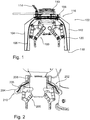
- Fig. 1 shows a gripper 100 for an industrial robot with a protective device 102 with a cover 104 and elastic traction means, such as 106.
- the protective device 102 serves to protect a person cooperating with the industrial robot in its work area from the gripper 100 and possibly a gripped workpiece.
- the protective device 102 has an annular fastening section 108 for fastening to the gripper 100.
- the gripper 100 has a connection flange 110 for connection to a corresponding connection flange of an industrial robot.
- the protective device 102 is fastened with its fastening section 108 to the gripper 100 in the vicinity of the connection flange 110.
- the sleeve 104 is slack and delimits a pressure chamber 112 that can be filled and / or evacuated.
- An air distribution channel is arranged in the fastening section 108.
- the pressure chamber 112 and the air distribution duct are connected to one another in a communicating manner.
- An air hose 114 is arranged on the fastening section 108.
- the air hose 114 is connected to the air distribution duct in a communicating manner.
- the pressure chamber 112 can be filled with air via the air hose 114 and the air distribution channel and / or air can be sucked out of the pressure chamber 112.
- the sheath 104 has a fixed end section 116, which is tightly connected to the fastening section 108, and a free end section 118.
- the elastic traction means 106 are arranged in the pressure chamber 112. In the present case, the traction means 106 are designed as rubber bands.
- the traction means 106 are each connected with one end to the fastening section 108 and with another end at the free end section 118 to the casing 104 in a tensile manner.
- the sleeve 104 has reinforcing elements, such as 120, in areas that bear against the gripper 100 when the pressure chamber 112 is filled.
- the reinforcement elements 120 are in the present case made of a plastic.
- Fig. 2 shows a gripper 200 for an industrial robot with a protective device 202 with a fillable and / or evacuable shell 204, traction means, such as 206, and actuators, such as 208.
- the traction means 206 each have one end with an actuator 208 and another end the free end section 210 is connected to the casing 204 in a tensile manner.
- the traction means 206 have a low elasticity and serve to transfer tensile forces from the actuators 208 to the casing 204.
- the actuators 208 serve to apply a traction force to the traction means 206 and each have a pneumatically actuatable piston-cylinder arrangement.
- Fig. 1 and the associated description.
- Fig. 3 shows an industrial robot 300 with a manipulator 302, a gripper 304 and a protective device 306, such as protective device 102 according to FIG Fig. 1 or protection device 202 according to Fig. 2 , when inflated.
- Fig. 4 shows the industrial robot 300 with protective device 306 in the retracted state.
- the envelope 308 is inflated and encloses the gripper 304, as in FIG Fig. 3 shown hood-like.
- the sleeve 308 is withdrawn and attached to the fastening section 310 of the protective device 306, as in FIG Fig. 4 shown, arranged folded up like a scarf.
- the sheath 308 is withdrawn when a workpiece is picked up or deposited with the aid of the gripper 304, and inflated when the manipulator 302 is moved with the gripper 304 with or without a workpiece. Retraction of the sheath 308 is supported by the traction means and, if necessary, actuators.
- FIGS. 1 and 2 as well as the associated description.
- Fig. 5 shows an industrial robot 400 with a gripper and a protective device 402 for an effector with an information technology user interface 404.
- the user interface 404 is used both for information output and for information input.
- the shell 406 has multiple chambers such as 410, 412.
- the chambers 410, 412 are separated from one another in a fluid-tight manner and form separate ones from one another Pressure rooms. In the event of a defect, in particular damage and / or leakage of individual chambers 410, 412, basic security is maintained.
- the chambers 410, 412 can be individually replaced or repaired.
- the protective device 402 has a light module for information output.
- the light module is arranged within the envelope 406.
- the sheath 406 is made of a translucent material.
- the shell 406 can be illuminated in different colors from the inside with the aid of the light module. This can be used to signal status information, a security status, an error or a required interaction, for example.
- the protective device 402 has a touchpad 408 for information output.
- the touchpad 408 is arranged on the outside of the case 406 and is firmly connected to the case 406.
- the touchpad 408 is flexible in such a way that the sleeve 406 with the touchpad 408 can be withdrawn from the effector.
- the touchpad 408 in the present case has symbols and digits.
- FIGS. 1 and 2 In addition, in particular on FIGS. 1 and 2 , on FIGS. 3 and 4 as well as the associated description.
Landscapes
- Engineering & Computer Science (AREA)
- Robotics (AREA)
- Mechanical Engineering (AREA)
- Manipulator (AREA)
Applications Claiming Priority (3)
| Application Number | Priority Date | Filing Date | Title |
|---|---|---|---|
| DE102016104940.9A DE102016104940A1 (de) | 2016-03-17 | 2016-03-17 | Schutzvorrichtung für einen Effektor eines Manipulators, Vorrichtung zum Manipulieren von Werkstücken und Verfahren zum Betätigen einer Vorrichtung zum Manipulieren von Werkstücken |
| PCT/EP2017/056295 WO2017158120A1 (fr) | 2016-03-17 | 2017-03-16 | Dispositif de protection pour un effecteur de manipulateur, dispositif pour manipuler des pièces et procédé pour actionner un dispositif pour manipuler des pièces |
| EP17711641.5A EP3429807B1 (fr) | 2016-03-17 | 2017-03-16 | Dispositif de protection pour un effecteur de manipulateur |
Related Parent Applications (2)
| Application Number | Title | Priority Date | Filing Date |
|---|---|---|---|
| EP17711641.5A Division-Into EP3429807B1 (fr) | 2016-03-17 | 2017-03-16 | Dispositif de protection pour un effecteur de manipulateur |
| EP17711641.5A Division EP3429807B1 (fr) | 2016-03-17 | 2017-03-16 | Dispositif de protection pour un effecteur de manipulateur |
Publications (2)
| Publication Number | Publication Date |
|---|---|
| EP3733362A1 true EP3733362A1 (fr) | 2020-11-04 |
| EP3733362B1 EP3733362B1 (fr) | 2023-06-07 |
Family
ID=58358600
Family Applications (2)
| Application Number | Title | Priority Date | Filing Date |
|---|---|---|---|
| EP20172011.7A Active EP3733362B1 (fr) | 2016-03-17 | 2017-03-16 | Dispositif de protection pour un effecteur d'un manipulateur, dispositif de manipulation de pièces et procédé de fonctionnement d'un dispositif de manipulation de pièces |
| EP17711641.5A Active EP3429807B1 (fr) | 2016-03-17 | 2017-03-16 | Dispositif de protection pour un effecteur de manipulateur |
Family Applications After (1)
| Application Number | Title | Priority Date | Filing Date |
|---|---|---|---|
| EP17711641.5A Active EP3429807B1 (fr) | 2016-03-17 | 2017-03-16 | Dispositif de protection pour un effecteur de manipulateur |
Country Status (5)
| Country | Link |
|---|---|
| US (1) | US11498226B2 (fr) |
| EP (2) | EP3733362B1 (fr) |
| CN (1) | CN108778643B (fr) |
| DE (1) | DE102016104940A1 (fr) |
| WO (1) | WO2017158120A1 (fr) |
Families Citing this family (32)
| Publication number | Priority date | Publication date | Assignee | Title |
|---|---|---|---|---|
| AT516097B1 (de) * | 2014-07-03 | 2016-09-15 | Blue Danube Robotics Gmbh | Schutzverfahren und Schutzvorrichtung für Handhabungsgerät |
| DE102017108618B4 (de) * | 2017-04-21 | 2021-08-05 | Deutsches Zentrum für Luft- und Raumfahrt e.V. | Verfahren zum Betätigen eines Roboters |
| USD873877S1 (en) * | 2017-06-21 | 2020-01-28 | Deutsches Zentrum für Luft- und Raumfahrt e.V. | Robot airbag |
| ES2760947T3 (es) | 2017-06-23 | 2020-05-18 | Comau Spa | Conjunto funcional para una máquina industrial, en concreto para un robot, que incluye una unidad funcional equipada con una cubierta de seguridad |
| EP3427904B1 (fr) * | 2017-07-13 | 2020-06-10 | Siemens Aktiengesellschaft | Système comprenant un manipulateur et un dispositif de limitation d'un espace de travail |
| US10137580B1 (en) * | 2017-09-15 | 2018-11-27 | Honda Motor Co., Ltd. | Systems and methods for robotic arm guard assemblies |
| USD863388S1 (en) * | 2017-12-20 | 2019-10-15 | Deutsches Zentrum für Luft- und Raumfahrt e.V. | Robot airbag |
| USD873878S1 (en) | 2018-01-17 | 2020-01-28 | Auris Health, Inc. | Robotic arm |
| USD932628S1 (en) | 2018-01-17 | 2021-10-05 | Auris Health, Inc. | Instrument cart |
| USD901694S1 (en) | 2018-01-17 | 2020-11-10 | Auris Health, Inc. | Instrument handle |
| JP7156865B2 (ja) * | 2018-08-30 | 2022-10-19 | 川崎重工業株式会社 | 緩衝装置及びそれを備えるロボット |
| DE102018122703A1 (de) * | 2018-09-17 | 2020-03-19 | E. Zoller Gmbh & Co. Kg | Greifervorrichtung mit einer Schutzeinheit |
| HU231104B1 (hu) * | 2018-10-11 | 2020-09-28 | B & O Kft. | Biztonsági burkolattal ellátott végeffektor szerkezet és eljárás a szerkezet alkalmazására |
| NL2022319B1 (en) * | 2018-12-28 | 2020-07-23 | Bollegraaf Patents And Brands B V | Suction unit for a robotic sorter |
| CN109732637A (zh) * | 2019-03-12 | 2019-05-10 | 哈工大机器人(山东)智能装备研究院 | 一种磁流体模块化机械夹手及工作方法 |
| JP7293844B2 (ja) * | 2019-04-25 | 2023-06-20 | セイコーエプソン株式会社 | ロボット |
| EP4069472A4 (fr) * | 2019-12-05 | 2024-03-20 | MAGNA Powertrain GmbH & Co KG | Procédé et configuration dans le cadre de la robotique sans barrière |
| USD1039578S1 (en) * | 2020-04-19 | 2024-08-20 | Tata Consultancy Services Limited | Robot gripper |
| CN111890406B (zh) * | 2020-08-07 | 2021-09-24 | 江苏昱博自动化设备有限公司 | 一种助力机械手用抱夹式夹具 |
| USD1009111S1 (en) * | 2020-12-15 | 2023-12-26 | Deutsches Zentrum für Luft- und Raumfahrt e.V. | Gripper jaw |
| EP4173780A1 (fr) | 2021-10-29 | 2023-05-03 | Deutsches Zentrum für Luft- und Raumfahrt e.V. | Dispositif de rétraction d'une enveloppe déformable entre une forme active et une forme réactive, dispositif fonctionnel comprenant une enveloppe déformable entre une forme active et un moule actif et procédé de fonctionnement d'un dispositif fonctionnel |
| DE102021128397A1 (de) | 2021-10-29 | 2023-05-04 | Deutsches Zentrum für Luft- und Raumfahrt e.V. | Rückziehvorrichtung für eine befüllbare und/oder evakuierbare biegeschlaffe Hülle, Funktionsvorrichtung mit einer befüllbaren und/oder evakuierbaren biegeschlaffen Hülle und Verfahren zum Betätigen einer Funktionsvorrichtung |
| JP1744835S (ja) * | 2022-10-13 | 2023-05-25 | ロボット用グリッパー | |
| DE202022106663U1 (de) | 2022-11-29 | 2023-04-26 | Deutsches Zentrum für Luft- und Raumfahrt e.V. | Schutzvorrichtung für einen Effektor |
| USD1061655S1 (en) * | 2022-12-21 | 2025-02-11 | Samsung Electronics Co., Ltd. | Hand for robot |
| USD1061656S1 (en) * | 2022-12-21 | 2025-02-11 | Samsung Electronics Co., Ltd. | Robot |
| JPWO2024166467A1 (fr) * | 2023-02-07 | 2024-08-15 | ||
| CN116277160B (zh) * | 2023-05-18 | 2023-08-29 | 深圳市大族机器人有限公司 | 一种防爆型多轴机器人 |
| SK10014Y1 (sk) * | 2023-08-30 | 2024-04-10 | Ing. Friga Peter, PhD. | Modulárne bezpečnostné zariadenie a zapojenie systému riadenia modulárneho bezpečnostného zariadenia |
| DE102023123838A1 (de) * | 2023-09-05 | 2025-03-06 | B. Braun New Ventures GmbH | Medizinisches Robotersystem mit angezeigter Aktivierungstaste sowie Aktivierungsverfahren |
| CN116945139B (zh) * | 2023-09-21 | 2024-01-26 | 连云港市东堡旋耕机械有限公司 | 一种开梗机加工用机械臂 |
| CN118636186B (zh) * | 2024-08-16 | 2024-10-15 | 成都大学 | 一种用于拾取电子元器件的柔性机械爪 |
Citations (11)
| Publication number | Priority date | Publication date | Assignee | Title |
|---|---|---|---|---|
| JPS6339786A (ja) * | 1986-08-05 | 1988-02-20 | 松下電器産業株式会社 | 工業用ロボツトの安全装置 |
| JPH09285992A (ja) | 1996-04-22 | 1997-11-04 | Yoshisuke Ueno | ロボットの安全装置 |
| DE102006044071A1 (de) | 2006-09-20 | 2008-04-03 | Deutsches Zentrum für Luft- und Raumfahrt e.V. | Roboter sowie Roboter-Schutzeinrichtung |
| DE102007062245A1 (de) * | 2007-12-21 | 2009-06-25 | Robert Bosch Gmbh | Kollisionsdetektionsvorrichtung sowie Handhabungsgerät |
| DE102012007242A1 (de) | 2012-03-09 | 2013-09-12 | Fraunhofer-Gesellschaft zur Förderung der angewandten Forschung e.V. | Vorrichtung und Verfahren zur sicheren Mensch-Roboter-Kooperation |
| WO2014008929A1 (fr) | 2012-07-10 | 2014-01-16 | Siemens Aktiengesellschaft | Agencement d'un robot et procédé de commande d'un robot |
| DE102012217764A1 (de) * | 2012-09-28 | 2014-06-12 | Bayerische Motoren Werke Aktiengesellschaft | Werkzeugschutzvorrichtung |
| DE202013105501U1 (de) * | 2013-12-03 | 2015-03-03 | Daimler Ag | Arbeitsvorrichtung |
| DE102014019033A1 (de) | 2013-12-25 | 2015-06-25 | Fanuc Corporation | Industrieroboter, der mit einem Menschen zusammenarbeitet und ein Schutzelement umfasst |
| DE102015005799A1 (de) * | 2015-05-06 | 2015-12-03 | Daimler Ag | Hülle für einen Roboter |
| DE102014221645A1 (de) * | 2014-10-24 | 2016-04-28 | Kuka Systems Gmbh | Flexibler Werkzeugschutz zum Einsatz mit einem Manipulator |
Family Cites Families (20)
| Publication number | Priority date | Publication date | Assignee | Title |
|---|---|---|---|---|
| US3499641A (en) * | 1967-10-02 | 1970-03-10 | Collins Radio Co | Fluid pressure actuated diaphragm workpiece clamping device |
| US3800890A (en) * | 1973-02-15 | 1974-04-02 | Ingersoll Rand Co | Dust control system |
| DE2437735B2 (de) * | 1974-08-06 | 1976-06-24 | Kernforschungsanlage Jülich GmbH, 517OJülich | Manipulator fuer bewegungen von in einem hochvakuumraum angeordneten gegenstaenden |
| US4523100A (en) * | 1982-08-11 | 1985-06-11 | R & D Associates | Optical vernier positioning for robot arm |
| DE9208980U1 (de) * | 1992-07-04 | 1993-11-04 | Kuka Schweißanlagen + Roboter GmbH, 86165 Augsburg | Überlastsicherung für eine Werkzeughalterung von Manipulatoren |
| US5653561A (en) * | 1993-07-23 | 1997-08-05 | May; Robert | Swarf boot |
| JPH1029191A (ja) * | 1996-07-11 | 1998-02-03 | Toyota Motor Corp | ロボット装置 |
| US6690208B2 (en) | 2002-02-23 | 2004-02-10 | Ati Industrial Automation, Inc. | Robot crash protector |
| JP2005231010A (ja) * | 2004-02-23 | 2005-09-02 | Fanuc Ltd | 表示装置 |
| JP2006187854A (ja) * | 2004-12-30 | 2006-07-20 | Jong Oh Kim | 携帯型穿孔機 |
| CN100335241C (zh) * | 2005-06-13 | 2007-09-05 | 西安思源职业学院 | 全气动组合式多功能工业机械手 |
| EP1810795A1 (fr) * | 2006-01-19 | 2007-07-25 | Abb Ab | Dispositif de sécurité pour un robot industriel avec sac élastique étanche comprenant un fluide ou gaz |
| DE102008019021A1 (de) * | 2008-04-15 | 2009-10-29 | Volkswagen Ag | Vorrichtung zum Schutz von Robotern vor Verschmutzung und/oder Beschädigung |
| US8529170B2 (en) * | 2010-08-25 | 2013-09-10 | Ernest Everington, JR. | Retractable drill mounted dust collector |
| CN202964522U (zh) * | 2012-11-23 | 2013-06-05 | 綦江齿轮传动有限公司 | 半自动装配机械手 |
| DE102013020137A1 (de) * | 2013-12-06 | 2015-06-11 | Daimler Ag | Arbeitsstation, insbesondere zum Herstellen eines Kraftwagens, sowie Verfahren zum Betreiben einer Arbeitsstation |
| JP6440385B2 (ja) | 2014-06-10 | 2018-12-19 | キヤノン株式会社 | ロボットアーム、表示装置およびロボットシステム |
| CN204658463U (zh) * | 2014-12-19 | 2015-09-23 | 库卡罗伯特有限公司 | 与机器人一起使用的安全系统 |
| CN106272565A (zh) * | 2016-09-27 | 2017-01-04 | 昆山穿山甲机器人有限公司 | 机器人防护装置 |
| US10328530B2 (en) * | 2016-09-27 | 2019-06-25 | The Boeing Company | Flexible and local laser shroud |
-
2016
- 2016-03-17 DE DE102016104940.9A patent/DE102016104940A1/de not_active Withdrawn
-
2017
- 2017-03-16 WO PCT/EP2017/056295 patent/WO2017158120A1/fr not_active Ceased
- 2017-03-16 EP EP20172011.7A patent/EP3733362B1/fr active Active
- 2017-03-16 CN CN201780017906.6A patent/CN108778643B/zh active Active
- 2017-03-16 EP EP17711641.5A patent/EP3429807B1/fr active Active
- 2017-03-16 US US16/085,783 patent/US11498226B2/en active Active
Patent Citations (11)
| Publication number | Priority date | Publication date | Assignee | Title |
|---|---|---|---|---|
| JPS6339786A (ja) * | 1986-08-05 | 1988-02-20 | 松下電器産業株式会社 | 工業用ロボツトの安全装置 |
| JPH09285992A (ja) | 1996-04-22 | 1997-11-04 | Yoshisuke Ueno | ロボットの安全装置 |
| DE102006044071A1 (de) | 2006-09-20 | 2008-04-03 | Deutsches Zentrum für Luft- und Raumfahrt e.V. | Roboter sowie Roboter-Schutzeinrichtung |
| DE102007062245A1 (de) * | 2007-12-21 | 2009-06-25 | Robert Bosch Gmbh | Kollisionsdetektionsvorrichtung sowie Handhabungsgerät |
| DE102012007242A1 (de) | 2012-03-09 | 2013-09-12 | Fraunhofer-Gesellschaft zur Förderung der angewandten Forschung e.V. | Vorrichtung und Verfahren zur sicheren Mensch-Roboter-Kooperation |
| WO2014008929A1 (fr) | 2012-07-10 | 2014-01-16 | Siemens Aktiengesellschaft | Agencement d'un robot et procédé de commande d'un robot |
| DE102012217764A1 (de) * | 2012-09-28 | 2014-06-12 | Bayerische Motoren Werke Aktiengesellschaft | Werkzeugschutzvorrichtung |
| DE202013105501U1 (de) * | 2013-12-03 | 2015-03-03 | Daimler Ag | Arbeitsvorrichtung |
| DE102014019033A1 (de) | 2013-12-25 | 2015-06-25 | Fanuc Corporation | Industrieroboter, der mit einem Menschen zusammenarbeitet und ein Schutzelement umfasst |
| DE102014221645A1 (de) * | 2014-10-24 | 2016-04-28 | Kuka Systems Gmbh | Flexibler Werkzeugschutz zum Einsatz mit einem Manipulator |
| DE102015005799A1 (de) * | 2015-05-06 | 2015-12-03 | Daimler Ag | Hülle für einen Roboter |
Also Published As
| Publication number | Publication date |
|---|---|
| EP3429807B1 (fr) | 2020-10-28 |
| WO2017158120A1 (fr) | 2017-09-21 |
| EP3733362B1 (fr) | 2023-06-07 |
| US20190047160A1 (en) | 2019-02-14 |
| EP3429807A1 (fr) | 2019-01-23 |
| DE102016104940A1 (de) | 2017-09-21 |
| CN108778643A (zh) | 2018-11-09 |
| US11498226B2 (en) | 2022-11-15 |
| CN108778643B (zh) | 2023-05-30 |
Similar Documents
| Publication | Publication Date | Title |
|---|---|---|
| EP3429807B1 (fr) | Dispositif de protection pour un effecteur de manipulateur | |
| EP3243608B1 (fr) | Procede de surveillance des etats de fonctionnement d'un actionneur commande par pression et actionneur commande par pression | |
| EP2016290B1 (fr) | Procede pour alimenter un cylindre moteur, commande de ce dernier, cylindre moteur et utilisation de celui-ci | |
| DE102014109262B4 (de) | Umsetzvorrichtung zum Ansaugen und Umsetzen eines Objekts | |
| DE102016111173A1 (de) | Verfahren zum Betreiben einer Greif- bzw. Spannvorrichtung | |
| DE202014104509U1 (de) | Schmiedehammer | |
| DE102021111279A1 (de) | Formsteuerung in greifsystemen und verfahren | |
| DE102017109291A1 (de) | Greifmodul | |
| EP3087022B1 (fr) | Dispositif de travail | |
| DE102006044071B4 (de) | Roboter sowie Roboter-Schutzeinrichtung | |
| DE102011119784A1 (de) | Fluidbetätigte Greifvorrichtung mit Sicherheitseinrichtung | |
| DE102014107642A1 (de) | Adaptereinrichtung | |
| DE102017108618B4 (de) | Verfahren zum Betätigen eines Roboters | |
| DE202019102610U1 (de) | Greifervorrichtung | |
| DE202018102683U1 (de) | Greifermodul und Vorrichtung zur Durchführung eines Steuerungsverfahrens für ein solches Greifermodul | |
| EP1166918B1 (fr) | Outil de rivetage | |
| DE202022106663U1 (de) | Schutzvorrichtung für einen Effektor | |
| DE2623013A1 (de) | Sprenggeraet mit im abstand vom sprengwerkzeug befindlichem druckluft- hydraulik-antrieb | |
| WO2023099239A1 (fr) | Dispositif d'usinage et système d'usinage | |
| DE102019107851A1 (de) | Robotergreifer sowie Verfahren zum Betrieb eines Robotergreifers | |
| DE102020108513B4 (de) | Mensch-Roboter-Kollaborations-Anlage | |
| DE102019202898A1 (de) | Antriebssystem | |
| DE102010022095A1 (de) | Sicherheitsvorrichtung zur Verhinderung von Unfällen mit Personenschäden durch Maschinen | |
| DE19806852C1 (de) | Sicherheitsvorrichtung für ein Transportsystem | |
| DE202013104544U1 (de) | Arbeitsvorrichtung |
Legal Events
| Date | Code | Title | Description |
|---|---|---|---|
| PUAI | Public reference made under article 153(3) epc to a published international application that has entered the european phase |
Free format text: ORIGINAL CODE: 0009012 |
|
| STAA | Information on the status of an ep patent application or granted ep patent |
Free format text: STATUS: THE APPLICATION HAS BEEN PUBLISHED |
|
| AC | Divisional application: reference to earlier application |
Ref document number: 3429807 Country of ref document: EP Kind code of ref document: P |
|
| AK | Designated contracting states |
Kind code of ref document: A1 Designated state(s): AL AT BE BG CH CY CZ DE DK EE ES FI FR GB GR HR HU IE IS IT LI LT LU LV MC MK MT NL NO PL PT RO RS SE SI SK SM TR |
|
| STAA | Information on the status of an ep patent application or granted ep patent |
Free format text: STATUS: REQUEST FOR EXAMINATION WAS MADE |
|
| 17P | Request for examination filed |
Effective date: 20210428 |
|
| RBV | Designated contracting states (corrected) |
Designated state(s): AL AT BE BG CH CY CZ DE DK EE ES FI FR GB GR HR HU IE IS IT LI LT LU LV MC MK MT NL NO PL PT RO RS SE SI SK SM TR |
|
| STAA | Information on the status of an ep patent application or granted ep patent |
Free format text: STATUS: EXAMINATION IS IN PROGRESS |
|
| GRAP | Despatch of communication of intention to grant a patent |
Free format text: ORIGINAL CODE: EPIDOSNIGR1 |
|
| STAA | Information on the status of an ep patent application or granted ep patent |
Free format text: STATUS: GRANT OF PATENT IS INTENDED |
|
| 17Q | First examination report despatched |
Effective date: 20221201 |
|
| INTG | Intention to grant announced |
Effective date: 20230103 |
|
| GRAS | Grant fee paid |
Free format text: ORIGINAL CODE: EPIDOSNIGR3 |
|
| GRAA | (expected) grant |
Free format text: ORIGINAL CODE: 0009210 |
|
| STAA | Information on the status of an ep patent application or granted ep patent |
Free format text: STATUS: THE PATENT HAS BEEN GRANTED |
|
| AC | Divisional application: reference to earlier application |
Ref document number: 3429807 Country of ref document: EP Kind code of ref document: P |
|
| AK | Designated contracting states |
Kind code of ref document: B1 Designated state(s): AL AT BE BG CH CY CZ DE DK EE ES FI FR GB GR HR HU IE IS IT LI LT LU LV MC MK MT NL NO PL PT RO RS SE SI SK SM TR |
|
| REG | Reference to a national code |
Ref country code: GB Ref legal event code: FG4D Free format text: NOT ENGLISH |
|
| REG | Reference to a national code |
Ref country code: CH Ref legal event code: EP Ref country code: AT Ref legal event code: REF Ref document number: 1573625 Country of ref document: AT Kind code of ref document: T Effective date: 20230615 Ref country code: DE Ref legal event code: R096 Ref document number: 502017014903 Country of ref document: DE |
|
| REG | Reference to a national code |
Ref country code: LT Ref legal event code: MG9D |
|
| REG | Reference to a national code |
Ref country code: NL Ref legal event code: MP Effective date: 20230607 |
|
| PG25 | Lapsed in a contracting state [announced via postgrant information from national office to epo] |
Ref country code: SE Free format text: LAPSE BECAUSE OF FAILURE TO SUBMIT A TRANSLATION OF THE DESCRIPTION OR TO PAY THE FEE WITHIN THE PRESCRIBED TIME-LIMIT Effective date: 20230607 Ref country code: NO Free format text: LAPSE BECAUSE OF FAILURE TO SUBMIT A TRANSLATION OF THE DESCRIPTION OR TO PAY THE FEE WITHIN THE PRESCRIBED TIME-LIMIT Effective date: 20230907 Ref country code: ES Free format text: LAPSE BECAUSE OF FAILURE TO SUBMIT A TRANSLATION OF THE DESCRIPTION OR TO PAY THE FEE WITHIN THE PRESCRIBED TIME-LIMIT Effective date: 20230607 |
|
| PG25 | Lapsed in a contracting state [announced via postgrant information from national office to epo] |
Ref country code: RS Free format text: LAPSE BECAUSE OF FAILURE TO SUBMIT A TRANSLATION OF THE DESCRIPTION OR TO PAY THE FEE WITHIN THE PRESCRIBED TIME-LIMIT Effective date: 20230607 Ref country code: NL Free format text: LAPSE BECAUSE OF FAILURE TO SUBMIT A TRANSLATION OF THE DESCRIPTION OR TO PAY THE FEE WITHIN THE PRESCRIBED TIME-LIMIT Effective date: 20230607 Ref country code: LV Free format text: LAPSE BECAUSE OF FAILURE TO SUBMIT A TRANSLATION OF THE DESCRIPTION OR TO PAY THE FEE WITHIN THE PRESCRIBED TIME-LIMIT Effective date: 20230607 Ref country code: LT Free format text: LAPSE BECAUSE OF FAILURE TO SUBMIT A TRANSLATION OF THE DESCRIPTION OR TO PAY THE FEE WITHIN THE PRESCRIBED TIME-LIMIT Effective date: 20230607 Ref country code: HR Free format text: LAPSE BECAUSE OF FAILURE TO SUBMIT A TRANSLATION OF THE DESCRIPTION OR TO PAY THE FEE WITHIN THE PRESCRIBED TIME-LIMIT Effective date: 20230607 Ref country code: GR Free format text: LAPSE BECAUSE OF FAILURE TO SUBMIT A TRANSLATION OF THE DESCRIPTION OR TO PAY THE FEE WITHIN THE PRESCRIBED TIME-LIMIT Effective date: 20230908 |
|
| PG25 | Lapsed in a contracting state [announced via postgrant information from national office to epo] |
Ref country code: FI Free format text: LAPSE BECAUSE OF FAILURE TO SUBMIT A TRANSLATION OF THE DESCRIPTION OR TO PAY THE FEE WITHIN THE PRESCRIBED TIME-LIMIT Effective date: 20230607 |
|
| PG25 | Lapsed in a contracting state [announced via postgrant information from national office to epo] |
Ref country code: SK Free format text: LAPSE BECAUSE OF FAILURE TO SUBMIT A TRANSLATION OF THE DESCRIPTION OR TO PAY THE FEE WITHIN THE PRESCRIBED TIME-LIMIT Effective date: 20230607 |
|
| PG25 | Lapsed in a contracting state [announced via postgrant information from national office to epo] |
Ref country code: IS Free format text: LAPSE BECAUSE OF FAILURE TO SUBMIT A TRANSLATION OF THE DESCRIPTION OR TO PAY THE FEE WITHIN THE PRESCRIBED TIME-LIMIT Effective date: 20231007 |
|
| PG25 | Lapsed in a contracting state [announced via postgrant information from national office to epo] |
Ref country code: SM Free format text: LAPSE BECAUSE OF FAILURE TO SUBMIT A TRANSLATION OF THE DESCRIPTION OR TO PAY THE FEE WITHIN THE PRESCRIBED TIME-LIMIT Effective date: 20230607 Ref country code: SK Free format text: LAPSE BECAUSE OF FAILURE TO SUBMIT A TRANSLATION OF THE DESCRIPTION OR TO PAY THE FEE WITHIN THE PRESCRIBED TIME-LIMIT Effective date: 20230607 Ref country code: RO Free format text: LAPSE BECAUSE OF FAILURE TO SUBMIT A TRANSLATION OF THE DESCRIPTION OR TO PAY THE FEE WITHIN THE PRESCRIBED TIME-LIMIT Effective date: 20230607 Ref country code: PT Free format text: LAPSE BECAUSE OF FAILURE TO SUBMIT A TRANSLATION OF THE DESCRIPTION OR TO PAY THE FEE WITHIN THE PRESCRIBED TIME-LIMIT Effective date: 20231009 Ref country code: IS Free format text: LAPSE BECAUSE OF FAILURE TO SUBMIT A TRANSLATION OF THE DESCRIPTION OR TO PAY THE FEE WITHIN THE PRESCRIBED TIME-LIMIT Effective date: 20231007 Ref country code: EE Free format text: LAPSE BECAUSE OF FAILURE TO SUBMIT A TRANSLATION OF THE DESCRIPTION OR TO PAY THE FEE WITHIN THE PRESCRIBED TIME-LIMIT Effective date: 20230607 Ref country code: CZ Free format text: LAPSE BECAUSE OF FAILURE TO SUBMIT A TRANSLATION OF THE DESCRIPTION OR TO PAY THE FEE WITHIN THE PRESCRIBED TIME-LIMIT Effective date: 20230607 |
|
| PG25 | Lapsed in a contracting state [announced via postgrant information from national office to epo] |
Ref country code: PL Free format text: LAPSE BECAUSE OF FAILURE TO SUBMIT A TRANSLATION OF THE DESCRIPTION OR TO PAY THE FEE WITHIN THE PRESCRIBED TIME-LIMIT Effective date: 20230607 |
|
| REG | Reference to a national code |
Ref country code: DE Ref legal event code: R097 Ref document number: 502017014903 Country of ref document: DE |
|
| PLBE | No opposition filed within time limit |
Free format text: ORIGINAL CODE: 0009261 |
|
| STAA | Information on the status of an ep patent application or granted ep patent |
Free format text: STATUS: NO OPPOSITION FILED WITHIN TIME LIMIT |
|
| PG25 | Lapsed in a contracting state [announced via postgrant information from national office to epo] |
Ref country code: DK Free format text: LAPSE BECAUSE OF FAILURE TO SUBMIT A TRANSLATION OF THE DESCRIPTION OR TO PAY THE FEE WITHIN THE PRESCRIBED TIME-LIMIT Effective date: 20230607 |
|
| PG25 | Lapsed in a contracting state [announced via postgrant information from national office to epo] |
Ref country code: SI Free format text: LAPSE BECAUSE OF FAILURE TO SUBMIT A TRANSLATION OF THE DESCRIPTION OR TO PAY THE FEE WITHIN THE PRESCRIBED TIME-LIMIT Effective date: 20230607 |
|
| 26N | No opposition filed |
Effective date: 20240308 |
|
| PG25 | Lapsed in a contracting state [announced via postgrant information from national office to epo] |
Ref country code: SI Free format text: LAPSE BECAUSE OF FAILURE TO SUBMIT A TRANSLATION OF THE DESCRIPTION OR TO PAY THE FEE WITHIN THE PRESCRIBED TIME-LIMIT Effective date: 20230607 Ref country code: IT Free format text: LAPSE BECAUSE OF FAILURE TO SUBMIT A TRANSLATION OF THE DESCRIPTION OR TO PAY THE FEE WITHIN THE PRESCRIBED TIME-LIMIT Effective date: 20230607 |
|
| REG | Reference to a national code |
Ref country code: CH Ref legal event code: PL |
|
| PG25 | Lapsed in a contracting state [announced via postgrant information from national office to epo] |
Ref country code: BG Free format text: LAPSE BECAUSE OF FAILURE TO SUBMIT A TRANSLATION OF THE DESCRIPTION OR TO PAY THE FEE WITHIN THE PRESCRIBED TIME-LIMIT Effective date: 20230607 |
|
| PG25 | Lapsed in a contracting state [announced via postgrant information from national office to epo] |
Ref country code: LU Free format text: LAPSE BECAUSE OF NON-PAYMENT OF DUE FEES Effective date: 20240316 |
|
| PG25 | Lapsed in a contracting state [announced via postgrant information from national office to epo] |
Ref country code: MC Free format text: LAPSE BECAUSE OF FAILURE TO SUBMIT A TRANSLATION OF THE DESCRIPTION OR TO PAY THE FEE WITHIN THE PRESCRIBED TIME-LIMIT Effective date: 20230607 |
|
| GBPC | Gb: european patent ceased through non-payment of renewal fee |
Effective date: 20240316 |
|
| PG25 | Lapsed in a contracting state [announced via postgrant information from national office to epo] |
Ref country code: MC Free format text: LAPSE BECAUSE OF FAILURE TO SUBMIT A TRANSLATION OF THE DESCRIPTION OR TO PAY THE FEE WITHIN THE PRESCRIBED TIME-LIMIT Effective date: 20230607 Ref country code: LU Free format text: LAPSE BECAUSE OF NON-PAYMENT OF DUE FEES Effective date: 20240316 Ref country code: BG Free format text: LAPSE BECAUSE OF FAILURE TO SUBMIT A TRANSLATION OF THE DESCRIPTION OR TO PAY THE FEE WITHIN THE PRESCRIBED TIME-LIMIT Effective date: 20230607 |
|
| REG | Reference to a national code |
Ref country code: BE Ref legal event code: MM Effective date: 20240331 |
|
| PG25 | Lapsed in a contracting state [announced via postgrant information from national office to epo] |
Ref country code: BE Free format text: LAPSE BECAUSE OF NON-PAYMENT OF DUE FEES Effective date: 20240331 |
|
| PG25 | Lapsed in a contracting state [announced via postgrant information from national office to epo] |
Ref country code: GB Free format text: LAPSE BECAUSE OF NON-PAYMENT OF DUE FEES Effective date: 20240316 |
|
| PG25 | Lapsed in a contracting state [announced via postgrant information from national office to epo] |
Ref country code: FR Free format text: LAPSE BECAUSE OF NON-PAYMENT OF DUE FEES Effective date: 20240331 |
|
| PG25 | Lapsed in a contracting state [announced via postgrant information from national office to epo] |
Ref country code: IE Free format text: LAPSE BECAUSE OF NON-PAYMENT OF DUE FEES Effective date: 20240316 |
|
| PG25 | Lapsed in a contracting state [announced via postgrant information from national office to epo] |
Ref country code: IE Free format text: LAPSE BECAUSE OF NON-PAYMENT OF DUE FEES Effective date: 20240316 Ref country code: GB Free format text: LAPSE BECAUSE OF NON-PAYMENT OF DUE FEES Effective date: 20240316 Ref country code: FR Free format text: LAPSE BECAUSE OF NON-PAYMENT OF DUE FEES Effective date: 20240331 Ref country code: BE Free format text: LAPSE BECAUSE OF NON-PAYMENT OF DUE FEES Effective date: 20240331 Ref country code: CH Free format text: LAPSE BECAUSE OF NON-PAYMENT OF DUE FEES Effective date: 20240331 |
|
| REG | Reference to a national code |
Ref country code: AT Ref legal event code: MM01 Ref document number: 1573625 Country of ref document: AT Kind code of ref document: T Effective date: 20240316 |
|
| PG25 | Lapsed in a contracting state [announced via postgrant information from national office to epo] |
Ref country code: AT Free format text: LAPSE BECAUSE OF NON-PAYMENT OF DUE FEES Effective date: 20240316 |
|
| PG25 | Lapsed in a contracting state [announced via postgrant information from national office to epo] |
Ref country code: CY Free format text: LAPSE BECAUSE OF FAILURE TO SUBMIT A TRANSLATION OF THE DESCRIPTION OR TO PAY THE FEE WITHIN THE PRESCRIBED TIME-LIMIT; INVALID AB INITIO Effective date: 20170316 |
|
| PG25 | Lapsed in a contracting state [announced via postgrant information from national office to epo] |
Ref country code: HU Free format text: LAPSE BECAUSE OF FAILURE TO SUBMIT A TRANSLATION OF THE DESCRIPTION OR TO PAY THE FEE WITHIN THE PRESCRIBED TIME-LIMIT; INVALID AB INITIO Effective date: 20170316 |
|
| PG25 | Lapsed in a contracting state [announced via postgrant information from national office to epo] |
Ref country code: TR Free format text: LAPSE BECAUSE OF FAILURE TO SUBMIT A TRANSLATION OF THE DESCRIPTION OR TO PAY THE FEE WITHIN THE PRESCRIBED TIME-LIMIT Effective date: 20230607 |
|
| PGFP | Annual fee paid to national office [announced via postgrant information from national office to epo] |
Ref country code: DE Payment date: 20260213 Year of fee payment: 10 |