EP3733432B1 - Towing arrangement and mine machine - Google Patents
Towing arrangement and mine machine Download PDFInfo
- Publication number
- EP3733432B1 EP3733432B1 EP19172195.0A EP19172195A EP3733432B1 EP 3733432 B1 EP3733432 B1 EP 3733432B1 EP 19172195 A EP19172195 A EP 19172195A EP 3733432 B1 EP3733432 B1 EP 3733432B1
- Authority
- EP
- European Patent Office
- Prior art keywords
- arrangement
- towing
- mine machine
- body part
- hydraulic actuator
- Prior art date
- Legal status (The legal status is an assumption and is not a legal conclusion. Google has not performed a legal analysis and makes no representation as to the accuracy of the status listed.)
- Active
Links
Images



Classifications
-
- B—PERFORMING OPERATIONS; TRANSPORTING
- B60—VEHICLES IN GENERAL
- B60D—VEHICLE CONNECTIONS
- B60D1/00—Traction couplings; Hitches; Draw-gear; Towing devices
- B60D1/14—Draw-gear or towing devices characterised by their type
- B60D1/143—Draw-gear or towing devices characterised by their type characterised by the mounting of the draw-gear on the towed vehicle
-
- B—PERFORMING OPERATIONS; TRANSPORTING
- B60—VEHICLES IN GENERAL
- B60D—VEHICLE CONNECTIONS
- B60D1/00—Traction couplings; Hitches; Draw-gear; Towing devices
- B60D1/01—Traction couplings or hitches characterised by their type
- B60D1/04—Hook or hook-and-hasp couplings
-
- B—PERFORMING OPERATIONS; TRANSPORTING
- B60—VEHICLES IN GENERAL
- B60D—VEHICLE CONNECTIONS
- B60D1/00—Traction couplings; Hitches; Draw-gear; Towing devices
- B60D1/24—Traction couplings; Hitches; Draw-gear; Towing devices characterised by arrangements for particular functions
- B60D1/242—Traction couplings; Hitches; Draw-gear; Towing devices characterised by arrangements for particular functions for supporting braking actions, e.g. braking means integrated with hitches; Braking sensors
-
- B—PERFORMING OPERATIONS; TRANSPORTING
- B60—VEHICLES IN GENERAL
- B60D—VEHICLE CONNECTIONS
- B60D1/00—Traction couplings; Hitches; Draw-gear; Towing devices
- B60D1/24—Traction couplings; Hitches; Draw-gear; Towing devices characterised by arrangements for particular functions
- B60D1/42—Traction couplings; Hitches; Draw-gear; Towing devices characterised by arrangements for particular functions for being adjustable
- B60D1/44—Traction couplings; Hitches; Draw-gear; Towing devices characterised by arrangements for particular functions for being adjustable horizontally
-
- B—PERFORMING OPERATIONS; TRANSPORTING
- B60—VEHICLES IN GENERAL
- B60T—VEHICLE BRAKE CONTROL SYSTEMS OR PARTS THEREOF; BRAKE CONTROL SYSTEMS OR PARTS THEREOF, IN GENERAL; ARRANGEMENT OF BRAKING ELEMENTS ON VEHICLES IN GENERAL; PORTABLE DEVICES FOR PREVENTING UNWANTED MOVEMENT OF VEHICLES; VEHICLE MODIFICATIONS TO FACILITATE COOLING OF BRAKES
- B60T13/00—Transmitting braking action from initiating means to ultimate brake actuator with power assistance or drive; Brake systems incorporating such transmitting means, e.g. air-pressure brake systems
- B60T13/10—Transmitting braking action from initiating means to ultimate brake actuator with power assistance or drive; Brake systems incorporating such transmitting means, e.g. air-pressure brake systems with fluid assistance, drive, or release
- B60T13/12—Transmitting braking action from initiating means to ultimate brake actuator with power assistance or drive; Brake systems incorporating such transmitting means, e.g. air-pressure brake systems with fluid assistance, drive, or release the fluid being liquid
-
- B—PERFORMING OPERATIONS; TRANSPORTING
- B60—VEHICLES IN GENERAL
- B60T—VEHICLE BRAKE CONTROL SYSTEMS OR PARTS THEREOF; BRAKE CONTROL SYSTEMS OR PARTS THEREOF, IN GENERAL; ARRANGEMENT OF BRAKING ELEMENTS ON VEHICLES IN GENERAL; PORTABLE DEVICES FOR PREVENTING UNWANTED MOVEMENT OF VEHICLES; VEHICLE MODIFICATIONS TO FACILITATE COOLING OF BRAKES
- B60T13/00—Transmitting braking action from initiating means to ultimate brake actuator with power assistance or drive; Brake systems incorporating such transmitting means, e.g. air-pressure brake systems
- B60T13/10—Transmitting braking action from initiating means to ultimate brake actuator with power assistance or drive; Brake systems incorporating such transmitting means, e.g. air-pressure brake systems with fluid assistance, drive, or release
- B60T13/66—Electrical control in fluid-pressure brake systems
- B60T13/662—Electrical control in fluid-pressure brake systems characterised by specified functions of the control system components
-
- B—PERFORMING OPERATIONS; TRANSPORTING
- B60—VEHICLES IN GENERAL
- B60T—VEHICLE BRAKE CONTROL SYSTEMS OR PARTS THEREOF; BRAKE CONTROL SYSTEMS OR PARTS THEREOF, IN GENERAL; ARRANGEMENT OF BRAKING ELEMENTS ON VEHICLES IN GENERAL; PORTABLE DEVICES FOR PREVENTING UNWANTED MOVEMENT OF VEHICLES; VEHICLE MODIFICATIONS TO FACILITATE COOLING OF BRAKES
- B60T7/00—Brake-action initiating means
- B60T7/12—Brake-action initiating means for automatic initiation; for initiation not subject to will of driver or passenger
- B60T7/20—Brake-action initiating means for automatic initiation; for initiation not subject to will of driver or passenger specially for trailers, e.g. in case of uncoupling of or overrunning by trailer
-
- B—PERFORMING OPERATIONS; TRANSPORTING
- B60—VEHICLES IN GENERAL
- B60D—VEHICLE CONNECTIONS
- B60D1/00—Traction couplings; Hitches; Draw-gear; Towing devices
- B60D1/48—Traction couplings; Hitches; Draw-gear; Towing devices characterised by the mounting
- B60D1/50—Traction couplings; Hitches; Draw-gear; Towing devices characterised by the mounting resiliently mounted
Definitions
- the invention relates to a towing arrangement for a mine machine.
- the invention further relates to a mine machine.
- a towing arrangement for a mine machine comprising
- a mine machine comprising the towing arrangement mentioned above.
- the towing element comprises a hook.
- the hydraulic actuator 3 comprises a hydraulic cylinder.
- the arrangement comprises at least two hydraulic actuators.
- the arrangement comprises at least two hydraulic actuators being arranged symmetrically in relation to a longitudinal axis of the arrangement.
- the body part comprises at least one extension arranged to extend sideward in relation to the longitudinal axis of the arrangement, the first part of the hydraulic actuator being attached to the extension, and the extension being arranged to forward the movement of the towing element in the hydraulic actuator.
- the arrangement comprises a returning element arranged to return the body part in its initial position in relation to the support element when towing element is released from the towing force.
- the returning element comprises at least one spring element.
- the arrangement comprises a stopper arrangement for transferring towing forces from the body part to the frame of the machine.
- the hydraulic actuator is arranged at least substantially parallel to a moving direction of the body part.
- the hydraulic actuator comprises connectors for connection to a hydraulic circuit of a braking system of the mine machine, and wherein hydraulic pressure created in the hydraulic actuator due to the towing force affecting to the towing element is arranged to release brakes of the mine machine.
- the support element comprises attaching means for attachment the support element to the mine machine.
- the arrangement is formed into a structural module retrofittable in a mine machine.
- a frame part of the mine machine is arranged to perform as the support element.
- Figure 1 is a schematic view of a part of a mine machine.
- the mine machine 6 may be e.g. a wheel loader. However, the mine machine 6 may be any type of a mining vehicle or a construction vehicle. The mine machine 6 may be provided with one or more working devices for executing designed work tasks at the work site. Thus, the mine machine 6 may also be a transport vehicle or dumper, a rock drilling rig, a bolting or reinforcing machine or a measuring machine, for example.
- the mine machine 6 comprises a towing arrangement 100 for towing the machine.
- the towing arrangement 100 comprises a body part (not shown in Figure 1 ) and a towing element 2 for allowing a towing tool to be connected to the towing arrangement 100 and thereby to the mine machine 6.
- the towing arrangement 100 is further provided with a hydraulic actuator (not shown In Figure 1 ) that comprises a first part attached to the body part, and a second part attachable to a support element 5.
- a hydraulic actuator (not shown In Figure 1 ) that comprises a first part attached to the body part, and a second part attachable to a support element 5.
- the support element 5 is fixed to the mine machine 6.
- a frame part 12 of the mine machine 6 is arranged to perform as said support element 5.
- the support element 5 is an additional element, i.e. not a part of the frame of the mine machine 6, that comprises attaching means by which the support element can be attached to the mine machine 6.
- the attaching means may comprise e.g. bolts or screws and corresponding holes.
- the arrangement 100 may be a structural module that is retrofittable in mine machines.
- the body part is movable in relation to the support element 5 in moving directions M so that the body part moves in relation to the support element 5 when a towing force is affecting to the towing element 2.
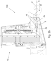
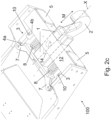
- FIGS 2a - 2d are schematic views of a detail of an arrangement in partial cross-section.
- the arrangement 100 has been arranged to a mine machine 6, in close proximity of a radiator of a cooler arrangement 15 of the mine machine.
- the proximity to the radiator is not necessary, i.e. the function of the arrangement 100 is not dependent on the radiator.
- the towing element 2 comprises a hook. In some another embodiments, such as shown in Figures, the towing element is other type of element, such as a loop.
- the hydraulic actuator 3 comprises a hydraulic cylinder that is arranged at least substantially parallel to a moving direction M of the body part 1.
- the hydraulic actuator is arranged to get shorter along with towing force affecting to the towing element 2.
- the hydraulic cylinder is connected to the hydraulic circuit of the braking system of the mine machine 6 so that hydraulic fluid may flow from the hydraulic cylinder to said hydraulic circuit and vice versa.
- the connection may comprise hydraulic hoses, couplings etc.
- a piston side chamber i.e. side opposite to a chamber of piston rod side, of the hydraulic cylinder is connected to the hydraulic circuit of the braking system of the mine machine 6.
- Volume of the piston side chamber is larger because the volume is not limited by piston rod, and thus a large volume flow of pressure fluid out from the cylinder is achieved compared to outer dimensions of the cylinder. This makes it possible to use smaller cylinders in the arrangement 100.
- hydraulic actuators 3 there are at least two hydraulic actuators 3 arranged parallel in the arrangement 100, as in the embodiment shown in the Figures.
- the hydraulic actuators 3 may be arranged symmetrically in relation to a longitudinal axis X of the arrangement.
- the hydraulic actuators 3, or just one hydraulic actuator 3 is/are arranged asymmetrically in relation to a longitudinal axis X of the arrangement.
- First part 4a of the hydraulic actuator is attached to extension 7 of the body part 1.
- the extension 7 extends sideward in relation to the longitudinal axis X of the arrangement.
- the shown embodiment has two extensions 7 directed opposite directions.
- the attachment of the first part 4a may be realized some other structure, too, provided that the structure may transfer movements of the body part 1 to the first part.
- the extension may extend in any direction in relation to the longitudinal axis X of the arrangement.
- Second part 4b of the hydraulic actuator is attached to a support element 5.
- the support element 5 is attached to a frame part 12 of the mining machine by attaching means 11.
- Said attaching means may comprise screws, bolts, nuts or any fixation means known per se.
- the support element 5 is attached to a frame part 12 by a welded joint.
- the hydraulic actuator 3 comprises connectors 10 for connecting said actuator to a hydraulic circuit of a braking system of the mine machine 6.
- the hydraulic pressure created in the hydraulic actuator 3 due to the towing force affecting to the towing element 2 is arranged to release brakes of the mine machine 6.
- the arrangement 100 comprises just one hydraulic actuator only.
- the hydraulic actuator may be arranged e.g. inside the body part 1.
- the arrangement comprises more than two, for instance three or four, hydraulic actuators.
- the arrangement 100 comprises at least one returning element 8 that is arranged to return the body part 1 in its initial position in relation to the support element 5 when towing element 2 is released from the towing force.
- the arrangement 100 comprises two coil spring elements as the returning element 8.
- the returning element 8 comprises another type of mechanical spring, such as a leaf spring.
- the returning element 8 comprises a gas spring.
- the spring elements are arranged separately from the hydraulic actuators 3.
- the returning element 8 is integrated in the hydraulic actuator 3, either inside or outside thereof.
- the chamber of piston rod side of the hydraulic cylinder is filled with gas, for example nitrogen. Said gas expands and its pressure drops when the cylinder is compressed. As the towing element 2 is released from the towing force, said gas in underpressurized state helps the cylinder to return in its initial length.
- the hydraulic cylinder comprises a spring, such as a coil spring, arranged inside the cylinder or around the exterior of the cylinder.
- the arrangement 100 comprises a stopper arrangement 9 that transfers at least a part of towing forces from the body part 1 to the frame of the machine.
- the stopper arrangement 9 comprises an oblong through hole 14 in the body part 1, and a pin 13 arranged movably in the hole 14.
- the pin 13 is attached to the frame of the machine and arranged perpendicular to the moving direction M of the body part 1.
- the pin abuts against the hole 14 when the machine 6 is being towed.
- the body part 1 comprises an abutting surface or extension (not shown) that abuts against a frame part of the mine machine and thus transfers towing forces in the frame of the mine machine.
- Figure 2c is showing the arrangement 100 in its rest state, i.e. when there is no towing force affecting to the towing element 2.
- the hydraulic actuators 3 and the returning elements 8 are in their extended states and the body part 1 retracted inside the structure of the mine machine. If the mine machine 6, for some reason, has lost vehicle power or hydraulic fluid pressure, an automatic fail-safe braking is on and brakes of the machine prevent the machine from moving.
- Figure 2d is showing the arrangement 100 when a towing force F is affecting to the towing element 2.
- the extensions 7 are pressing the hydraulic actuators 3 that thus get shorter.
- hydraulic fluid flows from the hydraulic actuators 3 to the hydraulic circuit of the braking system of the mine machine 6 releasing brakes thereof, allowing towing the mine machine 6.
- the brakes of the mine machine go on, and the mine machine does not move unintentionally.
- the brakes go on when the towing element 2 and the body part 1 have retracted completely.
- the brakes go on when the towing element 2 and the body part 1 have retracted a predetermined length towards the rest state.
- Said predetermined length may be, e.g. 50 mm - 200 mm, for instance 80 mm, 100 mm, or 150 mm.
Landscapes
- Engineering & Computer Science (AREA)
- Transportation (AREA)
- Mechanical Engineering (AREA)
- Regulating Braking Force (AREA)
- Drilling And Exploitation, And Mining Machines And Methods (AREA)
- Braking Arrangements (AREA)
- Agricultural Machines (AREA)
- Harvester Elements (AREA)
- Soil Working Implements (AREA)
- Motorcycle And Bicycle Frame (AREA)
- Vehicle Body Suspensions (AREA)
- Actuator (AREA)
Priority Applications (10)
| Application Number | Priority Date | Filing Date | Title |
|---|---|---|---|
| PL19172195.0T PL3733432T3 (pl) | 2019-05-02 | 2019-05-02 | Układ holowniczy i maszyna górnicza |
| EP19172195.0A EP3733432B1 (en) | 2019-05-02 | 2019-05-02 | Towing arrangement and mine machine |
| FIEP19172195.0T FI3733432T3 (fi) | 2019-05-02 | 2019-05-02 | Hinausjärjestely ja kaivoskone |
| CN202080030471.0A CN113710509B (zh) | 2019-05-02 | 2020-04-29 | 牵引装置和采掘机械 |
| PCT/EP2020/061879 WO2020221798A1 (en) | 2019-05-02 | 2020-04-29 | Towing arrangement and mine machine |
| EA202192494A EA202192494A1 (ru) | 2019-05-02 | 2020-04-29 | Буксирное устройство и шахтная машина |
| MX2021013403A MX2021013403A (es) | 2019-05-02 | 2020-04-29 | Disposicion de remolcado y maquina de mineria. |
| PE2021001734A PE20212128A1 (es) | 2019-05-02 | 2020-04-29 | Disposicion de remolcado y maquina de mineria |
| ZA2021/07480A ZA202107480B (en) | 2019-05-02 | 2021-10-05 | Towing arrangement and mine machine |
| CL2021002825A CL2021002825A1 (es) | 2019-05-02 | 2021-10-27 | Disposición de remolcado y máquina de minería. |
Applications Claiming Priority (1)
| Application Number | Priority Date | Filing Date | Title |
|---|---|---|---|
| EP19172195.0A EP3733432B1 (en) | 2019-05-02 | 2019-05-02 | Towing arrangement and mine machine |
Publications (2)
| Publication Number | Publication Date |
|---|---|
| EP3733432A1 EP3733432A1 (en) | 2020-11-04 |
| EP3733432B1 true EP3733432B1 (en) | 2023-07-12 |
Family
ID=66379742
Family Applications (1)
| Application Number | Title | Priority Date | Filing Date |
|---|---|---|---|
| EP19172195.0A Active EP3733432B1 (en) | 2019-05-02 | 2019-05-02 | Towing arrangement and mine machine |
Country Status (10)
| Country | Link |
|---|---|
| EP (1) | EP3733432B1 (pl) |
| CN (1) | CN113710509B (pl) |
| CL (1) | CL2021002825A1 (pl) |
| EA (1) | EA202192494A1 (pl) |
| FI (1) | FI3733432T3 (pl) |
| MX (1) | MX2021013403A (pl) |
| PE (1) | PE20212128A1 (pl) |
| PL (1) | PL3733432T3 (pl) |
| WO (1) | WO2020221798A1 (pl) |
| ZA (1) | ZA202107480B (pl) |
Families Citing this family (3)
| Publication number | Priority date | Publication date | Assignee | Title |
|---|---|---|---|---|
| CN113335398B (zh) * | 2021-08-06 | 2021-10-26 | 沛县迅驰专用车辆制造有限公司 | 一种可调节鞍式牵引连接器及其挂车 |
| EP4194234B1 (en) * | 2021-12-08 | 2026-07-01 | Sandvik Mining and Construction Oy | TOWING ARRANGEMENT FOR A BATTERY-POWERED MINING MACHINE AND BATTERY-POWERED MINING MACHINE |
| US12522033B2 (en) * | 2022-10-25 | 2026-01-13 | Toyota Motor Engineering & Manufacturing North America, Inc. | Pivoting tow hook assemblies and vehicles including same |
Family Cites Families (11)
| Publication number | Priority date | Publication date | Assignee | Title |
|---|---|---|---|---|
| GB1224491A (en) * | 1968-01-19 | 1971-03-10 | Ibbett Engineering Company Ltd | Trailer towing assembly |
| GB1367557A (en) * | 1972-08-04 | 1974-09-18 | Beach J M | Draft device |
| US4840256A (en) * | 1988-05-05 | 1989-06-20 | Webb James E | Surge brake apparatus for gooseneck trailers |
| RU2145011C1 (ru) * | 1998-10-13 | 2000-01-27 | Цыпцын Валерий Иванович | Гидравлический амортизатор для жесткого буксирного устройства |
| US8327982B2 (en) * | 2002-04-30 | 2012-12-11 | Titan International, Inc. | Actuator/coupler for towed and towing vehicle combination |
| US6848546B2 (en) * | 2002-10-02 | 2005-02-01 | Cequent Trailer Products, Inc. | Surge brake actuator |
| US8240778B2 (en) * | 2006-05-22 | 2012-08-14 | Continental Teves Ag & Co. Ohg | Hydraulic trailer brake system |
| CN102602255A (zh) * | 2011-03-07 | 2012-07-25 | 绿友机械集团股份有限公司 | 用于拖车的多功能牵引杆装置 |
| CN103434351A (zh) * | 2013-08-20 | 2013-12-11 | 张晓荣 | 一种弹簧拖钩 |
| US20150137482A1 (en) * | 2013-11-18 | 2015-05-21 | Teleswivel, Llc | Intelligent hitch apparatus for vehicles |
| EP3415398B1 (en) * | 2017-06-15 | 2021-08-11 | Sandvik Mining and Construction Oy | Mining machine having a towing hook |
-
2019
- 2019-05-02 PL PL19172195.0T patent/PL3733432T3/pl unknown
- 2019-05-02 EP EP19172195.0A patent/EP3733432B1/en active Active
- 2019-05-02 FI FIEP19172195.0T patent/FI3733432T3/fi active
-
2020
- 2020-04-29 CN CN202080030471.0A patent/CN113710509B/zh active Active
- 2020-04-29 WO PCT/EP2020/061879 patent/WO2020221798A1/en not_active Ceased
- 2020-04-29 PE PE2021001734A patent/PE20212128A1/es unknown
- 2020-04-29 EA EA202192494A patent/EA202192494A1/ru unknown
- 2020-04-29 MX MX2021013403A patent/MX2021013403A/es unknown
-
2021
- 2021-10-05 ZA ZA2021/07480A patent/ZA202107480B/en unknown
- 2021-10-27 CL CL2021002825A patent/CL2021002825A1/es unknown
Also Published As
| Publication number | Publication date |
|---|---|
| EP3733432A1 (en) | 2020-11-04 |
| MX2021013403A (es) | 2021-11-25 |
| FI3733432T3 (fi) | 2023-08-16 |
| CN113710509B (zh) | 2024-01-02 |
| PE20212128A1 (es) | 2021-11-05 |
| WO2020221798A1 (en) | 2020-11-05 |
| ZA202107480B (en) | 2025-04-30 |
| CL2021002825A1 (es) | 2022-06-24 |
| EA202192494A1 (ru) | 2022-03-31 |
| CN113710509A (zh) | 2021-11-26 |
| PL3733432T3 (pl) | 2023-09-25 |
Similar Documents
| Publication | Publication Date | Title |
|---|---|---|
| EP3733432A1 (en) | Towing arrangement and mine machine | |
| US7121185B2 (en) | Hydraulic cylinder having a snubbing valve | |
| EP3138805B1 (en) | Single-cylinder bolt stretching device and crane | |
| US20060022455A1 (en) | Hydraulic quick coupling | |
| US20140062178A1 (en) | Method and system for releasing parking brake of an anchored machine and a machine with the same | |
| CN110709306B (zh) | 牵引钩 | |
| CN112125181A (zh) | 起重机销接吊臂的电动致动组件 | |
| EP3061718B1 (en) | Telescopic boom extension device | |
| WO2017079792A1 (en) | A piston and cylinder system | |
| US7448477B2 (en) | Device for displacing an object a certain distance | |
| CN201647917U (zh) | 可自锁的多级液压伸缩杆机构 | |
| US20080115490A1 (en) | Hydraulic cylinder system | |
| KR100861487B1 (ko) | 향상된 자동안전기능을 갖춘 중장비용 어태치먼트 커플러 | |
| EP3895917B1 (en) | Towing arrangement and mobile work machine | |
| EP2501605B1 (en) | Apparatus for a variable gauge undercarriage | |
| US12325972B2 (en) | Control system for actuated pins | |
| US12449000B2 (en) | Compact actuated shear pin | |
| CN105164346B (zh) | 液压致动器 | |
| EA041554B1 (ru) | Буксирное устройство и шахтная машина | |
| CN210034043U (zh) | 一种储能式锁止机构 | |
| CN101331278A (zh) | 液压联结组件的安全设备 | |
| EP2438241B1 (en) | Kingpost assembly with hydraulically driven sideshift sliding carriage | |
| US20240336458A1 (en) | Jack with hydraulic lock | |
| JP2012512088A (ja) | 軌間可変車台用のロック装置 | |
| AU2020289732A1 (en) | Coupler for use on an Excavator Dipper Arm |
Legal Events
| Date | Code | Title | Description |
|---|---|---|---|
| PUAI | Public reference made under article 153(3) epc to a published international application that has entered the european phase |
Free format text: ORIGINAL CODE: 0009012 |
|
| STAA | Information on the status of an ep patent application or granted ep patent |
Free format text: STATUS: THE APPLICATION HAS BEEN PUBLISHED |
|
| AK | Designated contracting states |
Kind code of ref document: A1 Designated state(s): AL AT BE BG CH CY CZ DE DK EE ES FI FR GB GR HR HU IE IS IT LI LT LU LV MC MK MT NL NO PL PT RO RS SE SI SK SM TR |
|
| AX | Request for extension of the european patent |
Extension state: BA ME |
|
| STAA | Information on the status of an ep patent application or granted ep patent |
Free format text: STATUS: REQUEST FOR EXAMINATION WAS MADE |
|
| 17P | Request for examination filed |
Effective date: 20210504 |
|
| RBV | Designated contracting states (corrected) |
Designated state(s): AL AT BE BG CH CY CZ DE DK EE ES FI FR GB GR HR HU IE IS IT LI LT LU LV MC MK MT NL NO PL PT RO RS SE SI SK SM TR |
|
| GRAP | Despatch of communication of intention to grant a patent |
Free format text: ORIGINAL CODE: EPIDOSNIGR1 |
|
| STAA | Information on the status of an ep patent application or granted ep patent |
Free format text: STATUS: GRANT OF PATENT IS INTENDED |
|
| INTG | Intention to grant announced |
Effective date: 20230130 |
|
| GRAS | Grant fee paid |
Free format text: ORIGINAL CODE: EPIDOSNIGR3 |
|
| GRAA | (expected) grant |
Free format text: ORIGINAL CODE: 0009210 |
|
| STAA | Information on the status of an ep patent application or granted ep patent |
Free format text: STATUS: THE PATENT HAS BEEN GRANTED |
|
| AK | Designated contracting states |
Kind code of ref document: B1 Designated state(s): AL AT BE BG CH CY CZ DE DK EE ES FI FR GB GR HR HU IE IS IT LI LT LU LV MC MK MT NL NO PL PT RO RS SE SI SK SM TR |
|
| P01 | Opt-out of the competence of the unified patent court (upc) registered |
Effective date: 20230603 |
|
| REG | Reference to a national code |
Ref country code: CH Ref legal event code: EP |
|
| REG | Reference to a national code |
Ref country code: DE Ref legal event code: R096 Ref document number: 602019032414 Country of ref document: DE |
|
| REG | Reference to a national code |
Ref country code: IE Ref legal event code: FG4D |
|
| REG | Reference to a national code |
Ref country code: FI Ref legal event code: FGE |
|
| REG | Reference to a national code |
Ref country code: SE Ref legal event code: TRGR |
|
| REG | Reference to a national code |
Ref country code: LT Ref legal event code: MG9D |
|
| REG | Reference to a national code |
Ref country code: NL Ref legal event code: MP Effective date: 20230712 |
|
| REG | Reference to a national code |
Ref country code: AT Ref legal event code: MK05 Ref document number: 1586763 Country of ref document: AT Kind code of ref document: T Effective date: 20230712 |
|
| PG25 | Lapsed in a contracting state [announced via postgrant information from national office to epo] |
Ref country code: NL Free format text: LAPSE BECAUSE OF FAILURE TO SUBMIT A TRANSLATION OF THE DESCRIPTION OR TO PAY THE FEE WITHIN THE PRESCRIBED TIME-LIMIT Effective date: 20230712 |
|
| PG25 | Lapsed in a contracting state [announced via postgrant information from national office to epo] |
Ref country code: GR Free format text: LAPSE BECAUSE OF FAILURE TO SUBMIT A TRANSLATION OF THE DESCRIPTION OR TO PAY THE FEE WITHIN THE PRESCRIBED TIME-LIMIT Effective date: 20231013 |
|
| PG25 | Lapsed in a contracting state [announced via postgrant information from national office to epo] |
Ref country code: ES Free format text: LAPSE BECAUSE OF FAILURE TO SUBMIT A TRANSLATION OF THE DESCRIPTION OR TO PAY THE FEE WITHIN THE PRESCRIBED TIME-LIMIT Effective date: 20230712 |
|
| PG25 | Lapsed in a contracting state [announced via postgrant information from national office to epo] |
Ref country code: IS Free format text: LAPSE BECAUSE OF FAILURE TO SUBMIT A TRANSLATION OF THE DESCRIPTION OR TO PAY THE FEE WITHIN THE PRESCRIBED TIME-LIMIT Effective date: 20231112 |
|
| PG25 | Lapsed in a contracting state [announced via postgrant information from national office to epo] |
Ref country code: RS Free format text: LAPSE BECAUSE OF FAILURE TO SUBMIT A TRANSLATION OF THE DESCRIPTION OR TO PAY THE FEE WITHIN THE PRESCRIBED TIME-LIMIT Effective date: 20230712 Ref country code: PT Free format text: LAPSE BECAUSE OF FAILURE TO SUBMIT A TRANSLATION OF THE DESCRIPTION OR TO PAY THE FEE WITHIN THE PRESCRIBED TIME-LIMIT Effective date: 20231113 Ref country code: NO Free format text: LAPSE BECAUSE OF FAILURE TO SUBMIT A TRANSLATION OF THE DESCRIPTION OR TO PAY THE FEE WITHIN THE PRESCRIBED TIME-LIMIT Effective date: 20231012 Ref country code: LV Free format text: LAPSE BECAUSE OF FAILURE TO SUBMIT A TRANSLATION OF THE DESCRIPTION OR TO PAY THE FEE WITHIN THE PRESCRIBED TIME-LIMIT Effective date: 20230712 Ref country code: LT Free format text: LAPSE BECAUSE OF FAILURE TO SUBMIT A TRANSLATION OF THE DESCRIPTION OR TO PAY THE FEE WITHIN THE PRESCRIBED TIME-LIMIT Effective date: 20230712 Ref country code: IS Free format text: LAPSE BECAUSE OF FAILURE TO SUBMIT A TRANSLATION OF THE DESCRIPTION OR TO PAY THE FEE WITHIN THE PRESCRIBED TIME-LIMIT Effective date: 20231112 Ref country code: HR Free format text: LAPSE BECAUSE OF FAILURE TO SUBMIT A TRANSLATION OF THE DESCRIPTION OR TO PAY THE FEE WITHIN THE PRESCRIBED TIME-LIMIT Effective date: 20230712 Ref country code: GR Free format text: LAPSE BECAUSE OF FAILURE TO SUBMIT A TRANSLATION OF THE DESCRIPTION OR TO PAY THE FEE WITHIN THE PRESCRIBED TIME-LIMIT Effective date: 20231013 Ref country code: ES Free format text: LAPSE BECAUSE OF FAILURE TO SUBMIT A TRANSLATION OF THE DESCRIPTION OR TO PAY THE FEE WITHIN THE PRESCRIBED TIME-LIMIT Effective date: 20230712 Ref country code: AT Free format text: LAPSE BECAUSE OF FAILURE TO SUBMIT A TRANSLATION OF THE DESCRIPTION OR TO PAY THE FEE WITHIN THE PRESCRIBED TIME-LIMIT Effective date: 20230712 |
|
| REG | Reference to a national code |
Ref country code: DE Ref legal event code: R097 Ref document number: 602019032414 Country of ref document: DE |
|
| PG25 | Lapsed in a contracting state [announced via postgrant information from national office to epo] |
Ref country code: SM Free format text: LAPSE BECAUSE OF FAILURE TO SUBMIT A TRANSLATION OF THE DESCRIPTION OR TO PAY THE FEE WITHIN THE PRESCRIBED TIME-LIMIT Effective date: 20230712 Ref country code: RO Free format text: LAPSE BECAUSE OF FAILURE TO SUBMIT A TRANSLATION OF THE DESCRIPTION OR TO PAY THE FEE WITHIN THE PRESCRIBED TIME-LIMIT Effective date: 20230712 Ref country code: EE Free format text: LAPSE BECAUSE OF FAILURE TO SUBMIT A TRANSLATION OF THE DESCRIPTION OR TO PAY THE FEE WITHIN THE PRESCRIBED TIME-LIMIT Effective date: 20230712 Ref country code: DK Free format text: LAPSE BECAUSE OF FAILURE TO SUBMIT A TRANSLATION OF THE DESCRIPTION OR TO PAY THE FEE WITHIN THE PRESCRIBED TIME-LIMIT Effective date: 20230712 Ref country code: SK Free format text: LAPSE BECAUSE OF FAILURE TO SUBMIT A TRANSLATION OF THE DESCRIPTION OR TO PAY THE FEE WITHIN THE PRESCRIBED TIME-LIMIT Effective date: 20230712 |
|
| PLBE | No opposition filed within time limit |
Free format text: ORIGINAL CODE: 0009261 |
|
| STAA | Information on the status of an ep patent application or granted ep patent |
Free format text: STATUS: NO OPPOSITION FILED WITHIN TIME LIMIT |
|
| PG25 | Lapsed in a contracting state [announced via postgrant information from national office to epo] |
Ref country code: IT Free format text: LAPSE BECAUSE OF FAILURE TO SUBMIT A TRANSLATION OF THE DESCRIPTION OR TO PAY THE FEE WITHIN THE PRESCRIBED TIME-LIMIT Effective date: 20230712 |
|
| 26N | No opposition filed |
Effective date: 20240415 |
|
| PG25 | Lapsed in a contracting state [announced via postgrant information from national office to epo] |
Ref country code: SI Free format text: LAPSE BECAUSE OF FAILURE TO SUBMIT A TRANSLATION OF THE DESCRIPTION OR TO PAY THE FEE WITHIN THE PRESCRIBED TIME-LIMIT Effective date: 20230712 |
|
| PG25 | Lapsed in a contracting state [announced via postgrant information from national office to epo] |
Ref country code: BG Free format text: LAPSE BECAUSE OF FAILURE TO SUBMIT A TRANSLATION OF THE DESCRIPTION OR TO PAY THE FEE WITHIN THE PRESCRIBED TIME-LIMIT Effective date: 20230712 |
|
| PG25 | Lapsed in a contracting state [announced via postgrant information from national office to epo] |
Ref country code: BG Free format text: LAPSE BECAUSE OF FAILURE TO SUBMIT A TRANSLATION OF THE DESCRIPTION OR TO PAY THE FEE WITHIN THE PRESCRIBED TIME-LIMIT Effective date: 20230712 |
|
| REG | Reference to a national code |
Ref country code: CH Ref legal event code: PL |
|
| PG25 | Lapsed in a contracting state [announced via postgrant information from national office to epo] |
Ref country code: MC Free format text: LAPSE BECAUSE OF FAILURE TO SUBMIT A TRANSLATION OF THE DESCRIPTION OR TO PAY THE FEE WITHIN THE PRESCRIBED TIME-LIMIT Effective date: 20230712 |
|
| PG25 | Lapsed in a contracting state [announced via postgrant information from national office to epo] |
Ref country code: LU Free format text: LAPSE BECAUSE OF NON-PAYMENT OF DUE FEES Effective date: 20240502 |
|
| GBPC | Gb: european patent ceased through non-payment of renewal fee |
Effective date: 20240502 |
|
| PG25 | Lapsed in a contracting state [announced via postgrant information from national office to epo] |
Ref country code: MC Free format text: LAPSE BECAUSE OF FAILURE TO SUBMIT A TRANSLATION OF THE DESCRIPTION OR TO PAY THE FEE WITHIN THE PRESCRIBED TIME-LIMIT Effective date: 20230712 Ref country code: LU Free format text: LAPSE BECAUSE OF NON-PAYMENT OF DUE FEES Effective date: 20240502 Ref country code: CH Free format text: LAPSE BECAUSE OF NON-PAYMENT OF DUE FEES Effective date: 20240531 |
|
| REG | Reference to a national code |
Ref country code: BE Ref legal event code: MM Effective date: 20240531 |
|
| PG25 | Lapsed in a contracting state [announced via postgrant information from national office to epo] |
Ref country code: IE Free format text: LAPSE BECAUSE OF NON-PAYMENT OF DUE FEES Effective date: 20240502 |
|
| PG25 | Lapsed in a contracting state [announced via postgrant information from national office to epo] |
Ref country code: BE Free format text: LAPSE BECAUSE OF NON-PAYMENT OF DUE FEES Effective date: 20240531 |
|
| PG25 | Lapsed in a contracting state [announced via postgrant information from national office to epo] |
Ref country code: GB Free format text: LAPSE BECAUSE OF NON-PAYMENT OF DUE FEES Effective date: 20240502 |
|
| PG25 | Lapsed in a contracting state [announced via postgrant information from national office to epo] |
Ref country code: CY Free format text: LAPSE BECAUSE OF FAILURE TO SUBMIT A TRANSLATION OF THE DESCRIPTION OR TO PAY THE FEE WITHIN THE PRESCRIBED TIME-LIMIT; INVALID AB INITIO Effective date: 20190502 |
|
| PG25 | Lapsed in a contracting state [announced via postgrant information from national office to epo] |
Ref country code: HU Free format text: LAPSE BECAUSE OF FAILURE TO SUBMIT A TRANSLATION OF THE DESCRIPTION OR TO PAY THE FEE WITHIN THE PRESCRIBED TIME-LIMIT; INVALID AB INITIO Effective date: 20190502 |
|
| PG25 | Lapsed in a contracting state [announced via postgrant information from national office to epo] |
Ref country code: TR Free format text: LAPSE BECAUSE OF FAILURE TO SUBMIT A TRANSLATION OF THE DESCRIPTION OR TO PAY THE FEE WITHIN THE PRESCRIBED TIME-LIMIT Effective date: 20230712 |
|
| PGFP | Annual fee paid to national office [announced via postgrant information from national office to epo] |
Ref country code: PL Payment date: 20260415 Year of fee payment: 8 |
|
| PGFP | Annual fee paid to national office [announced via postgrant information from national office to epo] |
Ref country code: DE Payment date: 20260331 Year of fee payment: 8 |
|
| PGFP | Annual fee paid to national office [announced via postgrant information from national office to epo] |
Ref country code: SE Payment date: 20260402 Year of fee payment: 8 Ref country code: FI Payment date: 20260515 Year of fee payment: 8 |
|
| PGFP | Annual fee paid to national office [announced via postgrant information from national office to epo] |
Ref country code: CZ Payment date: 20260427 Year of fee payment: 8 |
|
| PGFP | Annual fee paid to national office [announced via postgrant information from national office to epo] |
Ref country code: FR Payment date: 20260421 Year of fee payment: 8 |