EP3733448A1 - Système de compensation automatique d'inclinaison à l'intérieur d'un véhicule - Google Patents
Système de compensation automatique d'inclinaison à l'intérieur d'un véhicule Download PDFInfo
- Publication number
- EP3733448A1 EP3733448A1 EP20168220.0A EP20168220A EP3733448A1 EP 3733448 A1 EP3733448 A1 EP 3733448A1 EP 20168220 A EP20168220 A EP 20168220A EP 3733448 A1 EP3733448 A1 EP 3733448A1
- Authority
- EP
- European Patent Office
- Prior art keywords
- assembly
- axis
- pendulum
- air
- pendulum arrangement
- Prior art date
- Legal status (The legal status is an assumption and is not a legal conclusion. Google has not performed a legal analysis and makes no representation as to the accuracy of the status listed.)
- Granted
Links
Images







Classifications
-
- B—PERFORMING OPERATIONS; TRANSPORTING
- B60—VEHICLES IN GENERAL
- B60N—SEATS SPECIALLY ADAPTED FOR VEHICLES; VEHICLE PASSENGER ACCOMMODATION NOT OTHERWISE PROVIDED FOR
- B60N2/00—Seats specially adapted for vehicles; Arrangement or mounting of seats in vehicles
- B60N2/24—Seats specially adapted for vehicles; Arrangement or mounting of seats in vehicles for particular purposes or particular vehicles
- B60N2/38—Seats specially adapted for vehicles; Arrangement or mounting of seats in vehicles for particular purposes or particular vehicles specially constructed for use on tractors or like off-road vehicles
- B60N2/39—Seats tiltable to compensate for roll inclination of vehicles
-
- B—PERFORMING OPERATIONS; TRANSPORTING
- B60—VEHICLES IN GENERAL
- B60N—SEATS SPECIALLY ADAPTED FOR VEHICLES; VEHICLE PASSENGER ACCOMMODATION NOT OTHERWISE PROVIDED FOR
- B60N2/00—Seats specially adapted for vehicles; Arrangement or mounting of seats in vehicles
- B60N2/02—Seats specially adapted for vehicles; Arrangement or mounting of seats in vehicles the seat or part thereof being movable, e.g. adjustable
- B60N2/0224—Non-manual adjustments, e.g. with electrical operation
- B60N2/0244—Non-manual adjustments, e.g. with electrical operation with logic circuits
-
- B—PERFORMING OPERATIONS; TRANSPORTING
- B60—VEHICLES IN GENERAL
- B60N—SEATS SPECIALLY ADAPTED FOR VEHICLES; VEHICLE PASSENGER ACCOMMODATION NOT OTHERWISE PROVIDED FOR
- B60N2/00—Seats specially adapted for vehicles; Arrangement or mounting of seats in vehicles
- B60N2/02—Seats specially adapted for vehicles; Arrangement or mounting of seats in vehicles the seat or part thereof being movable, e.g. adjustable
- B60N2/04—Seats specially adapted for vehicles; Arrangement or mounting of seats in vehicles the seat or part thereof being movable, e.g. adjustable the whole seat being movable
- B60N2/10—Seats specially adapted for vehicles; Arrangement or mounting of seats in vehicles the seat or part thereof being movable, e.g. adjustable the whole seat being movable tiltable
-
- B—PERFORMING OPERATIONS; TRANSPORTING
- B60—VEHICLES IN GENERAL
- B60N—SEATS SPECIALLY ADAPTED FOR VEHICLES; VEHICLE PASSENGER ACCOMMODATION NOT OTHERWISE PROVIDED FOR
- B60N2/00—Seats specially adapted for vehicles; Arrangement or mounting of seats in vehicles
- B60N2/50—Seat suspension devices
- B60N2/501—Seat suspension devices actively controlled suspension, e.g. electronic control
-
- B—PERFORMING OPERATIONS; TRANSPORTING
- B60—VEHICLES IN GENERAL
- B60N—SEATS SPECIALLY ADAPTED FOR VEHICLES; VEHICLE PASSENGER ACCOMMODATION NOT OTHERWISE PROVIDED FOR
- B60N2/00—Seats specially adapted for vehicles; Arrangement or mounting of seats in vehicles
- B60N2/50—Seat suspension devices
- B60N2/502—Seat suspension devices attached to the base of the seat
-
- B—PERFORMING OPERATIONS; TRANSPORTING
- B60—VEHICLES IN GENERAL
- B60N—SEATS SPECIALLY ADAPTED FOR VEHICLES; VEHICLE PASSENGER ACCOMMODATION NOT OTHERWISE PROVIDED FOR
- B60N2/00—Seats specially adapted for vehicles; Arrangement or mounting of seats in vehicles
- B60N2/50—Seat suspension devices
- B60N2/52—Seat suspension devices using fluid means
- B60N2/522—Seat suspension devices using fluid means characterised by dampening means
-
- B—PERFORMING OPERATIONS; TRANSPORTING
- B60—VEHICLES IN GENERAL
- B60N—SEATS SPECIALLY ADAPTED FOR VEHICLES; VEHICLE PASSENGER ACCOMMODATION NOT OTHERWISE PROVIDED FOR
- B60N2/00—Seats specially adapted for vehicles; Arrangement or mounting of seats in vehicles
- B60N2/50—Seat suspension devices
- B60N2/52—Seat suspension devices using fluid means
- B60N2/525—Seat suspension devices using fluid means using gas
Definitions
- the invention relates to a system for automatic inclination compensation within a vehicle according to the preamble of claim 1.
- an inclination compensation is particularly relevant, which is necessary due to rotational movements which vehicles, for example utility vehicles such as tractors, carry out around their main axes when traveling over uneven ground.
- These rotational movements are also known as swaying (rotation around the longitudinal axis) and pitching (rotation around the transverse axis).
- the vehicle drives with its left front wheel over an unevenness such as a large stone.
- the vehicle then experiences both a rotational movement around the longitudinal axis and a rotational movement around the transverse axis. If the vehicle drives on a slope and parallel to it, it only experiences a rotational movement around the longitudinal axis, for example.
- the entire vehicle is thus deflected around the longitudinal axis for the duration of the slope.
- a vehicle seat which is rigidly connected to the body, for example, is accordingly also deflected about the longitudinal axis. It goes without saying that this tendency is unpleasant for the driver after a certain degree and / or a certain duration.
- An assembly that has a center of gravity that is higher than an axis of rotation about which the assembly can perform a rotational movement is known to be unstable. Returning the assembly to the basic position, which in the present case means eliminating the deflection, and thus compensating for inclination, can only function with a restoring force.
- the object of the present invention is therefore to develop a system for automatically resetting the deflection which activates the actuator system in a purely mechanical manner.
- a system for automatic inclination compensation within a vehicle comprising a first assembly and a second assembly that is pivotably connected to the first assembly by means of a first axis, the system further comprising a pendulum arrangement, which by means of one above the first axis and on one The second axis arranged at the upper end of the pendulum assembly is pivotably connected to the second assembly, a deflection of the pendulum assembly relative to the second assembly being detectable.
- the system works with regard to a deflection around the X axis, which for example represents a longitudinal axis of the vehicle, and thus provides roll compensation. Furthermore, the system also functions with regard to a deflection about the Y-axis, which for example represents a transverse axis of the vehicle, and thus provides pitch compensation.
- the system can refer to a body of the vehicle as the first assembly and to the deflection of a vehicle seat as the second assembly (as described in more detail below), but the system is not limited to this.
- an ambulance with a body (first assembly) as well as a couch or a transport device for accident victims (second assembly) could also be provided with such a system for automatic inclination compensation in order to be able to transport an accident victim without inclination.
- the arrangement described ensures that pivoting of the first assembly and / or the second assembly can be detected by means of the arrangement of the pendulum assembly.
- a deflection of the first assembly leads to a deflection of the second assembly and initially, for example, not or also to a deflection of the pendulum arrangement.
- the suspension of the pendulum arrangement at the upper end ensures, however, that this pendulum arrangement can swing freely around the second axis, so that the lower end of the pendulum arrangement follows the force of gravity and relatively quickly returns to a basic position, which it was, for example, before the deflection.
- This provides a simple way of detecting the deflection of the second assembly, the current position of which, for example, deviates from the basic position of the second assembly, relative to the pendulum arrangement.
- the basic positions are present when the coordinate system of the first assembly, the second assembly and / or the pendulum arrangement is each arranged identically to the global coordinate system.
- the global coordinate system is a Cartesian coordinate system with mutually perpendicular axes X (global longitudinal direction), Y (global latitude) and Z (global height direction), the global height direction being arranged parallel to the vector of gravity within the scope of the invention.
- the first axis and the second axis lie on a common straight line which is arranged running in a vertical direction of the vehicle.
- the height direction of the vehicle preferably corresponds to the global height direction at least when the vehicle is in a non-deflected state.
- the global height direction is arranged parallel to the vector of gravity. It should be mentioned, however, that the system also works when the first axis and the second axis do not lie on this common straight line, but rather have an offset in the horizontal direction, for example.
- the first assembly preferably comprises a support beam element, the longitudinal extent of which in the first basic position is arranged parallel to the global width direction.
- the first assembly preferably comprises a bearing element for the first axis, which is rigidly connected to the supporting beam element, preferably to its top side.
- the supporting beam element and the bearing element together form an assembly which, preferably has exactly one mirror symmetry axis.
- the above-mentioned common straight line forms this mirror symmetry axis.
- the pendulum arrangement comprises a pendulum element which can be deflected about the second axis by means of a pivot bearing providing damping.
- a degree of damping of the damping provided can be freely selected within a certain range by a suitable choice of the pivot bearing.
- the degree of deflection of the pendulum arrangement which can also be referred to as amplitude, is presently positively correlated to the duration of the deflection. For example, it is provided that only deflections which last longer than one second can be detected by means of the system according to the invention.
- the pendulum element is designed in a T-shape and / or in the form of a hammer, which or which is arranged upside down at least in the third basic position.
- the pendulum element can have a substantially rectilinear shape between the first and the second end, whereby it is also advantageous here if the center of mass of the pendulum element is arranged as described above.
- the system according to the invention does not require any sensors, actuators and / or any control system for detecting the deflection. It is particularly advantageous if only a single degree of deflection in a first direction and / or a single degree of deflection in a second direction can be detected by means of the system. This refinement makes it possible to construct the system in a simple and cost-conscious manner, in contrast to a system which can determine several or all degrees of deflection.
- this single degree of deflection can be viewed as a limit value up to which deflection is still tolerated. Countermeasures only have to be taken when the limit value is reached. At the same time, a qualitative statement can be made about whether the limit value has already been reached or not; consequently about whether the deflection is still greater than or equal to zero and at the same time smaller than the limit value or whether the deflection has already reached the limit value.
- the second assembly comprises at least one first contact element for closing an electrical circuit. It is also advantageous if the pendulum arrangement has at least one second contact element for closing the circuit at a lower end.
- the at least one first and the at least one second contact element are preferably spaced apart from one another in the second and third basic positions and can be arranged in contact with one another by means of the deflection of the pendulum arrangement relative to the second assembly. The circuit is therefore not closed at least when the second and third basic positions are present together or when the second assembly and the pendulum arrangement have an identical deflection.
- the first and the second contact element for closing a circuit in the contacting state form, for example, a closed circuit, that is, both charge carriers of the circuit flow through them.
- the first contact element contacts the second contact element, the first contact element being designed as a purely mechanical contact element and / or the second contact element as an electrical switch, contactless switch, Hall sensor, magnetic switch, reed switch, etc.
- “contacting” is to be understood to mean that the first and the second contact element approach each other far enough that it is necessary to close the circuit.
- first contact elements and / or at least two second contact elements are arranged for closing the circuit.
- first contact elements and / or at least two second contact elements are arranged for closing the circuit.
- exactly two first contact elements and / or exactly two second contact elements are arranged for closing the circuit.
- the number of first contact elements is preferably identical to the number of second contact elements.
- power line elements such as power cables can be arranged within the system, which are arranged starting from the first contact element via the pendulum arrangement to the second contact element.
- the charge carriers of the circuit are transported at least in sections through electrically conductive sections of the system which are not formed by cables;
- conductive sections are formed by power cables, by one or more sections of the pendulum element and / or by one or more sections of the second assembly.
- the second assembly has a rocker element which is rotatably mounted about the first axis and on the top of which the at least one first contact element is arranged.
- This rocker element offers a solid basis for further elements of the second assembly and at the same time a simple possibility of arranging the at least one first contact element.
- the second assembly has a first bar element which is arranged perpendicular to the rocker element and rigidly connected to it, the pivot bearing for the pendulum element being arranged at an upper end of the first bar element.
- the bar element and the rocker element preferably jointly form the shape of the letter T, which is arranged upside down in relation to the height direction of the second assembly.
- At least one of the elements of the second assembly is preferably arranged mirror-symmetrically to the common straight line and / or to a further straight line.
- the rocker element and / or the bar element are preferably designed in each case mirror-symmetrically to the common straight line and / or to the further straight line.
- the rocker element and / or the bar element are preferably designed in each case mirror-symmetrically to the common straight line and / or to the further straight line.
- first contact elements are arranged, these are preferably arranged mirror-symmetrically to one another in the first and second basic position with respect to the common straight line and / or with respect to the further straight line.
- second contact elements are arranged, they are preferably arranged mirror-symmetrically to one another in the first and second basic position with respect to the common straight line and / or with respect to the further straight line.
- the pendulum element and / or the pendulum assembly is preferably designed to be mirror-symmetrical.
- the axis belonging to the mirror symmetry is the common straight line and / or the further straight line.
- Closing the circuit can therefore advantageously serve as indirect detection of the deflection of the pendulum element.
- the consumer element is designed as an actuator system, by means of which the deflection of the pendulum arrangement relative to the second assembly can be traced back.
- all or more of these variants comprise a device in order to provide a resilient suspension of the vehicle seat.
- This device is, for example, a rotary suspension damping system which enables or cushions and / or dampens a rotation about the first axis.
- a rotary suspension damping system which enables or cushions and / or dampens a rotation about the first axis.
- the system only works statically and / or is not provided with such a device.
- the actuator system preferably comprises a pump, for example an air pump, which works in combination with a pneumatic system. It can also be that the actuator system has a mechanical system that provides a motor and a transmission. A combination of a mechanical and a pneumatic system is also possible.
- air spring and air muscle are used.
- An air muscle describes an element which has devices such as bores at both ends, by means of which it can be connected to other elements particularly securely and, for example, by means of a rotary joint.
- An air spring is connected, for example, to other elements via a mere contact formation, for example along a support surface.
- the actuator system comprises at least one pneumatic element designed as an air muscle or air spring with a first end and a second end and an air reservoir arranged between the first and the second end, an amount of air in the air reservoir of the pneumatic element being variable.
- the first end of the air muscle is arranged above the second end of the air muscle and is rotatably connected to the first assembly, and that the second end of the air muscle is rotatably connected to the second assembly.
- the first end of the air spring is arranged above the second end of the air spring and rotatably connected to the second assembly, and the second end of the air spring is rotatably connected to the first assembly.
- the distance between the first and the second end of the pneumatic element can be changed. This also changes a deflection of the second assembly compared to the first assembly.
- the second end of the at least one pneumatic element designed as an air muscle is arranged between the rocker element and the first assembly or at the same height as the rocker element.
- the first end of the air muscle is, however, arranged above the rocker element.
- the air muscle is preferably arranged above the rocker element.
- the air muscle is preferably arranged above, most preferably completely above, the supporting beam element.
- the first assembly comprises a frame element which is preferably rigidly connected to the support beam element and / or is arranged above it.
- the first end of the air muscle is preferably rotatably connected to the frame element.
- the first end of the air muscle according to the first preferred variant is preferred arranged contacting the first assembly and the second end of the air muscle contacting the second assembly.
- the at least one pneumatic element is designed as an air spring, which is arranged directly between the rocker element and the first assembly.
- the air spring is preferably arranged below, mostly preferably completely below, the rocker element.
- the air spring is preferably arranged above, most preferably completely above the supporting beam element.
- the first and the second end of the air spring are therefore preferably arranged between the rocker element and the first assembly.
- the first end of the air spring is arranged in contact with the second assembly and the second end of the air spring is arranged in contact with the first assembly.
- the actuator system for returning the second assembly according to the first variant comprises exactly one first and exactly one second air muscle and is otherwise free of further air muscles and air springs. It is also preferred that the actuator system for returning the second assembly according to the second variant comprises exactly one first and exactly one second air spring and is otherwise free of further air muscles or air springs.
- These air muscles or air springs are preferably arranged next to one another in the first and second basic position in a global width direction and / or extend in terms of their extent between the first and the second end parallel to the global height direction.
- a first amount of air in the first air muscle or in the first air spring can be controlled independently of a second air amount in the second air muscle or in the second air spring; the same applies preferably vice versa.
- the return of the second assembly to the second basic position can thus take place much faster and more evenly with two air muscles or with two air springs.
- the actuator system comprises at least one first electric drive, by means of which the second assembly can be actively rotated about the first axis.
- This electric drive and / or its transmission elements are preferably connected directly to the first axle.
- the electric drive is preferably arranged in contact with the supporting beam element of the first assembly.
- the supporting beam element of the first assembly preferably represents a bearing device for the electric drive.
- the actuator system comprises at least one second electric drive, by means of which the second axis can be actively rotated, with a second bar element, which is connected at its center to the second axis, by means of at least two spring elements is connected to the rocker element.
- This second electric drive and / or its transmission elements are preferably connected directly to the second axle.
- the second assembly is therefore cushioned by means of the described arrangement and / or returned to the second basic position.
- the second beam element is mounted pivotably directly about the second axis or is rigidly connected to it.
- the second bar element it is possible for the second bar element to be arranged pivotably about a fourth axis, which preferably also lies on the common straight line.
- the fourth axis is arranged on the second beam element; thus the second beam element is indirectly connected to the second axle.
- the first assembly comprises a wheel system of the vehicle and the second assembly comprises a vehicle seat of the vehicle.
- At least one first damper unit is arranged, which by means of a first end with the second assembly, in particular with a third beam element, and by means of a second end also with the second assembly , in particular with the rocker element, is connected.
- the third bar element is preferably arranged pivotably about a third axis arranged on the first bar element.
- the third axis preferably lies on the straight line common to the first and second axes and is connected to the first beam element, for example.
- This first damper unit ensures a reduction in energy in the oscillating system and thus a gentle return of the second assembly to the basic position.
- Precisely two first damper units are preferably arranged, which can be arranged in particular symmetrically to one another with reference to the common straight line of the first and second axis and / or to the further straight line.
- the pendulum arrangement comprises the above-mentioned pivot bearing with a damping function.
- the pendulum arrangement can comprise a brake, for example a silicone brake, which is preferably arranged at the upper end of the pendulum arrangement.
- At least one second damper unit can be arranged which damps the movement of the pendulum element and in particular its movement back into the basic position.
- this second damper unit is arranged perpendicular to the common straight line of the first and second axes and / or perpendicular to the longitudinal direction / longitudinal axis of the pendulum element in its basic position.
- this second damper unit is arranged perpendicular to the common straight line of the first and second axes and / or perpendicular to the longitudinal direction / longitudinal axis of the pendulum element in its basic position.
- exactly two second damper units are arranged, which are arranged in a mirror-inverted manner in relation to the common straight line and / or to the longitudinal direction / longitudinal axis of the pendulum element in its basic position.
- the at least one second damper unit can be in a first state, according to which damping work can be performed, and in a second state, according to which no damping work can be performed; this preferably applies to at least one direction of movement.
- the second state corresponds to the state in which the piston is completely retracted into the cylinder.
- the at least one second damper unit is preferably arranged with one end each contacting the lower end of the pendulum arrangement.
- the pendulum arrangement is designed with the silicone brake and / or two second damper units.
- the present figures each describe a system S according to which the first assembly 10 comprises a wheel system 100 of the vehicle V and the second assembly 20 a vehicle seat 200 of the vehicle V.
- FIG. 1 a greatly simplified schematic diagram of the system S according to the invention for automatic inclination compensation within a vehicle V is shown in advance.
- a Cartesian coordinate system with the global axes X, Y and Z is illustrated, with Z being arranged here parallel to the direction of gravity.
- the axes X and Y span a horizontal plane which is arranged perpendicular to the gravity vector (axis Z). It goes without saying that the exact alignment of the two axes X and Y can be freely selected within the framework of the boundary conditions described.
- the axis X which is perpendicular to Z and Y, is arranged parallel to the longitudinal direction Vx of the vehicle V in the present case.
- the height direction Vz of the vehicle V (apart from the second assembly 20 and the pendulum arrangement 30) also means the height direction of the first assembly 10;
- the subsurface U and thus also the first assembly 10 of the vehicle V have an incline a with respect to the global width direction Y.
- the vehicle V drives parallel to a slope and thus executes a rotational movement about the longitudinal axis Vx (rolling movement).
- the first assembly 10 is therefore compared to its basic position P10 (see Fig. 2a ) deflected about the axis X by the angle a.
- a second assembly 20 is connected to the first assembly 10 so as to be pivotable about an axis A1.
- This second assembly 20 is already shown in its state returned to the second basic position P20; the inclination compensation has already taken place, so that in particular the rocker element 21 of the second assembly 20 shown has already been aligned horizontally again, i.e. within a plane spanned by the X and Y axes of the global coordinate system.
- the longitudinal extension of the rocker element 21 is arranged parallel to the global width direction Y in the present case.
- the longitudinal direction 20x of the second assembly 20 is arranged parallel to the global longitudinal direction X. Furthermore, the width direction 20y of the second assembly 20 is arranged parallel to the global width direction Y. In addition, the height direction 20z of the second assembly 20 is arranged parallel to the global height direction Z. The second assembly 20 is thus in its home position P20.
- system S for automatic inclination compensation within a vehicle V, comprising the first assembly 10 and the second assembly 20 pivotably connected to the first assembly 10 by means of a first axis A1, the system S further comprising a pendulum arrangement 30, which is pivotally connected to the second assembly 20 by means of a second axis A2 arranged above the first axis A1 and at an upper end 31 of the pendulum assembly 30, a deflection of the pendulum assembly 30 relative to the second assembly 20 being detectable.
- the Figures 2a to 2d illustrate a chronological sequence of events that can occur when driving parallel to a slope.
- the vehicle V is initially arranged on a subsurface U which is arranged parallel to the global latitude direction Y. Accordingly, the coordinate systems of the vehicle V, the first assembly 10, the second assembly 20 and the pendulum arrangement 30 are all arranged in accordance with the global coordinate system.
- the first assembly 10, the second assembly 20 and the pendulum arrangement 30 are each in the basic position P10, P20, P30.
- the vehicle V is arranged on a ground U which is arranged at an angle ⁇ to the global latitude direction Y.
- the coordinate systems of the vehicle V, the first assembly 10, the second assembly 20 and the pendulum arrangement 30 at least with respect to their height direction Vz, 20z, 30z and their width direction Vy, 20y, 30y are all offset by the angle ⁇ to the global coordinate system.
- the coordinate systems of the vehicle V, the first assembly 10 and the second assembly 20 are still arranged offset by the angle ⁇ to the global coordinate system, at least with respect to their height direction Vz, 20z and their width direction Vy, 20y.
- the Pendulum arrangement 30 has already been arranged parallel to global height direction Z again with regard to its height axis 30z due to the effect of gravity on pendulum arrangement 30.
- the pendulum arrangement 30 is thus deflected relative to the second assembly 20; alternatively, this could of course also be formulated in such a way that the second assembly 20 is deflected with respect to the pendulum arrangement 30.
- One of the first contact elements 40 and one of the second contact elements 41 thus form contact with one another. This closes a circuit C, whereby a consumer 50 designed as an actuator system 51 is activated within the circuit C (see FIG Fig. 2e ).
- the actuator system 51 now actively returns the second assembly 20 to its home position P20.
- This returned state is simplified as described in accordance with FIG Fig. 1 and again using the Fig. 2d shown. While the pendulum arrangement 30 and the second assembly 20 are already in the basic position P20, P30 again, FIG Fig. 2d that the coordinate systems of the vehicle V and of the first assembly 10 are still arranged offset by the angle ⁇ to the global coordinate system at least with respect to their height direction Vz and their width direction Vy.
- the first axis A1 and the second axis A2 lie on a common straight line 60 which is arranged running in a height direction Vz of the vehicle V.
- the height direction Vz of the vehicle V corresponds to the global height direction Z at least in a non-deflected state of the vehicle V.
- Fig. 2e shows that the first assembly 10 in the present case comprises a support beam element 11, the longitudinal extent of which in the first basic position P10 is arranged parallel to the global width direction Y.
- the first assembly 10 comprises a bearing element 12 for the first axis A1, which is rigidly connected to an upper side of the support beam element 11.
- the support beam element 11 and the bearing element 12 together form an assembly which has exactly one mirror symmetry axis, which in the present case is formed by the common straight line 60.
- the pendulum arrangement 30 in the present case comprises a pendulum element 33 which can be deflected about the second axis A2 by means of a rotary bearing 34 providing damping (see above everything Fig. 2e ).
- a distance d2 between a center of mass M33 of the pendulum element 33 and a lower end 32 of the pendulum arrangement 30 is smaller than a distance d1 between the center of mass M33 of the pendulum element 33 and the upper end 31 of the pendulum arrangement 30.
- the pendulum element 33 is designed in a T-shape and in the form of a hammer, which or which is at least in the third basic position P30 of the pendulum arrangement 30 (see FIG Fig. 2a ) is arranged upside down.
- the system S according to the invention does not require any sensors, actuators and no control to detect the deflection.
- the system S shown only a single degree of deflection in a first direction 300 and a single degree of deflection in a second direction 301 can be detected.
- the second assembly 20 in the present case comprises two first contact elements 40 for closing a circuit C.
- the pendulum arrangement 30 has two second contact elements 41 for closing the circuit C at its lower end 32.
- both first 40 and both second contact elements 41 are in the third basic position P30 (see FIG Fig. 2a ) at a distance from one another and can be arranged in contact with one another by means of the deflection of the pendulum arrangement 30 relative to the second assembly 20 (see FIG Fig. 2e ).
- the circuit C is therefore not closed at least when the second P20 and the third basic position P30 are present together.
- power cables (not shown) are presently arranged within the system S, which are arranged starting from the first contact element 40 via the pendulum arrangement 30 to the second contact element 41.
- the second assembly 20 in the present case has a rocker element 21 which is rotatably mounted about the first axis A1 and on the top side 21a of which the two first contact elements 40 are arranged.
- the second assembly 20 in the present case has a first bar element 22 which is arranged perpendicular to the rocker element 21 and is rigidly connected to it, the pivot bearing 34 for the pendulum element 33 being arranged at an upper end 22a of the first bar element 22.
- the first bar element 22 and the rocker element 21 together form the shape of the letter T in the present case, which is arranged upside down in relation to the height direction 20z of the second assembly 20.
- the rocker element 21 and the bar element 22 are each configured mirror-symmetrically to the common straight line 60.
- the two first contact elements 40 are arranged mirror-symmetrically to one another in relation to the common straight line 60.
- the two second contact elements 41 are arranged mirror-symmetrically to one another in relation to the common straight line 60.
- the pendulum element 33 and the pendulum assembly 30 are designed to be mirror-symmetrical.
- the axis belonging to the mirror symmetry is the common straight line 60.
- Closing the circuit C thus serves in the present case as indirect detection of the deflection of the pendulum element 33 with respect to the second assembly 20.
- a consumer element 50 is arranged within the circuit C.
- the consumer element 50 is designed as an actuator system 51, by means of which the deflection of the pendulum arrangement 30 relative to the second assembly 20 can be traced back.
- the actuator system 51 comprises two air muscles 70, 71, each with a first end 701, 711 and a second end 702, 712 as well as an air reservoir 703, 713 arranged between the first 701, 711 and the second end 702, 712 Air muscle 70, 71 variable, the first end 701, 711 of the air muscle 70, 71 being rotatably connected to the first assembly 10 and the second end 702, 712 of the air muscle 70, 71 being rotatably connected to the second assembly 20.
- the two air muscles 70, 71 are arranged next to one another in the first P10 and second basic position P20 in the global width direction Y and extend between the first 701, 711 and the second end 702, 712 parallel to the global height direction Z.
- a first air volume in the first air reservoir 703 of the first air muscle 70 can be controlled independently of a second air volume in the second air reservoir 713 of the second air muscle 71; the same applies vice versa.
- the sequence of steps for deflecting and returning the second assembly 20 is only based on the first preferred variant ( Figures 2a-2d ) shown.
- the second, third and fourth preferred variant of the system S is shown in such a way that the first assembly 10, the second assembly 20 and the pendulum arrangement 30 are each in the basic position P10, P20, P30. It goes without saying that the four preferred variants of the system S preferably differ only in terms of the actuator system 51 used.
- the actuator system 51 comprises two air springs 70 ', 71', each with a first end 701 ', 711' and a second end 702 ', 712' and one between the first 701 ', 711 and the second end 702', 712 ' arranged air storage 703 ', 713'.
- a quantity of air in the air reservoir 703 ', 713' of the air spring 70 ', 71' can be changed, the first end 701 ', 711' of the air spring 70 ', 71' each being rotatable with the second assembly 20 and the second end 702 ', 712' of the air spring 70 ', 71' is each rotatably connected to the first assembly 10.
- the two air springs 70, 71; 70 ', 71' are arranged next to one another in the first P10 and second basic position P20 in the global width direction Y and extend in terms of their extent between the first 701, 711; 701 ', 711' and the second end 702,712; 702 ', 712' parallel to the global altitude direction Z.
- a first amount of air is in the first air reservoir 703; 703 'of the first air spring 70; 70 'independently of a second air volume in the second air reservoir 713; 713 'of the second air spring 71; 71 'controllable; the same applies vice versa.
- the second end 702, 712 of the air muscles 70, 71 are each arranged at the same height as the rocker element 21.
- the first end 701, 711 of the air muscles 70, 71 is arranged above the rocker element 21 in the present case.
- both air muscles 70, 71 are completely above the supporting beam element 11 arranged.
- the first assembly 10 comprises a frame element 13 which is rigidly connected to the support beam element 11 and is arranged above it.
- the first end 701, 711 of the air muscles 70, 71 are each rotatably connected to the frame element 13 via axes A7, A8.
- the second end 702, 712 of the air muscles 70, 71 is each rotatably connected to the rocker element 21 via axes A9, A10.
- the first end 701, 711 of the air muscles 70, 71 is thus arranged in contact with the first assembly 10 and the second end 702, 712 of the air muscles 70, 71 in contact with the second assembly 20.
- both air springs 70 ′, 71 ′ are arranged directly between the rocker element 21 and the first assembly 10.
- both air springs 70 ′, 71 ′ are arranged completely below the rocker element 21 and completely above the support beam element 11.
- the first 701 ', 711' and the second end 702 ', 712' of the air springs 70 ', 71' are thus arranged between the rocker element 21 and the first assembly 10.
- the first end 701 ', 711' of the air springs 70 ', 71' are each arranged in contact with the second assembly 20 and the second end 702 ', 712' of the air springs 70 ', 71' in each case in contact with the first assembly 10.
- the actuator system 51 comprises a first electric drive 80, by means of which the second assembly 20 can be actively rotated about the first axis A1.
- this third variant does not include any suspension / damping device which resiliently mounts the entire system.
- this electric drive 80 and its transmission elements are directly connected to the first axis A1;
- the first axis A1 is configured by a shaft element which is rigidly connected to the second assembly 20 and is arranged rotatably with respect to the first assembly 10.
- the electric drive 80 is arranged in contact with the supporting beam element 11 of the first assembly 10, so that the supporting beam element 11 of the first assembly 10 represents a bearing device for the electric drive 80.
- the actuator system 51 comprises a second electric drive 81, by means of which the second axis A2 or a shaft element configuring the second axis A2 can be actively rotated, with a second bar element 82, which is connected at its center with the second axis A2 and is present is arranged pivotably directly about the second axis A2, is connected to the rocker element 21 by means of at least two spring elements 83.
- this second electric drive 81 and its transmission elements are directly connected to the second
- the second assembly 20 is therefore cushioned by means of the described arrangement and returned to its basic position P20.
- Figures 6a to 6c each part of the first assembly 10 and the second assembly 20, which is shown here without a vehicle seat. So shows Figure 6a a front view of the system S, the Figure 6b a rear view of the system S and FIG. 6c a side view of the system S.
- the actuator system 51 shown accordingly includes exactly two air muscles 70, 71 with a first end 701, 711 and a second end 702, 712 as well as an air reservoir 703, 713 arranged between the first 701, 711 and the second end 702, 712. An amount of air in the air reservoir 703, 713 can be changed.
- the first end 701, 711 of the air muscles 70, 71 is arranged above the second end 702, 712 of the air muscles 70, 71.
- the first end of the air muscles 70, 71 is rotatably connected to the first assembly 10 and the second end 702, 712 of the air muscles 70, 71 is rotatably connected to the second assembly 20.
- the system S comprises the pendulum arrangement 30, which is pivotably connected to the second assembly 20 by means of the second axis A2 arranged above the first axis A1 and at the upper end 31 of the pendulum arrangement 30.
- the actuator system 51 of the system can include its electric drive, for example the second electric drive 81 or another, by means of which the second axis A2 can be actively rotated, with a fourth bar element 94, which is at its center with the second axis A2 is connected, by means of which two air muscles 70, 71 are connected to the rocker element 21.
- the fourth bar element 94 is arranged to be pivotable about a fifth axis A5, which lies on the common straight line 60.
- the fifth axis A5 is arranged on the first beam element 22; thus the second beam element 82 is indirectly connected to the second axis A2.
- both first damper units 90 are arranged symmetrically to one another with reference to the common straight line 60 of the first A1 and the second axis A2.
- the third bar element 93 is arranged pivotably about a third axis A3 arranged on the first bar element 22, the third axis A3 lying on the common straight line 60 of the first A1 and second axis A3.
- the Figure 6a shows that the pendulum arrangement 30 comprises a pendulum element 33 which can be deflected about the second axis A2 by means of a pivot bearing 34 providing damping.
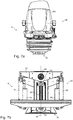
- Figure 7a shows part of the first assembly 10 and the second assembly 20, which comprises a vehicle seat 200 of the vehicle V.
- parts of the system S have been completely or partially omitted in some figures for better clarity.
- Figure 7a a view of the system S with vehicle seat 200
- Figure 7b shows the same view without the vehicle seat 200.
- Figure 7c which shows a rear view of system S with vehicle seat 200
- FIG Figure 7d shows the same view without the vehicle seat 200.
- Figure 7e a top view of the system S with vehicle seat 200
- the Figure 7f shows the same view without the vehicle seat 200.
- Figure 7g a side view of the system S with vehicle seat 200
- Figure 7h shows the same view without the vehicle seat 200.
- the system S comprises the pendulum arrangement 30, which is pivotably connected to the second assembly 20 by means of the second axis A2 arranged above the first axis A1 and at the upper end 31 of the pendulum arrangement 30.
- the actuator system 51 of the system S comprises a second electric drive 81, by means of which the second axis A2 can be actively rotated, with a second beam element 82, which is connected at its center to second axis A2, is connected to rocker element 21 by means of at least two spring elements 83.
- the second beam element 82 is arranged pivotably about a fourth axis A4, which lies on the common straight line 60.
- the fourth axis A4 is arranged on the first beam element 22; thus the second beam element 82 is indirectly connected to the second axis A2.
- FIGS Figures 5a and 5b show in particular the Figure 7b , 7c and 7d that exactly two first damper units 90 are arranged, which are connected by means of a first end 91 to a third bar element 93 of the second assembly 20 and by means of a second end 92 to the rocker element 21 of the second assembly 20.
- both first damper units 90 are arranged symmetrically to one another with reference to the common straight line 60 of the first A1 and the second axis A2.
- the third bar element 93 is arranged pivotably about a third axis A3 arranged on the first bar element 22, the third axis A3 lying on the common straight line 60 of the first A1 and second axis A3.
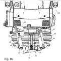
- the Figure 8b shows that the pendulum arrangement 30 comprises a pendulum element 33 which can be deflected about the second axis A2 by means of a pivot bearing 34 providing damping.
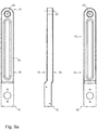
- FIG. 9a A front view, a side view and a rear view of a pendulum element 33 of the pendulum assembly 30 having an upper 31 and a lower end 32 are shown. The position of the second axis A2 is also marked.
- the pendulum arrangement 30 comprises a brake, in this case a silicone brake 96, which in the present case is arranged at the upper end 31 of the pendulum arrangement 30. It is also shown that the pendulum arrangement 30 has two second contact elements 41 at a lower end 32 for closing the circuit C, the second contact elements 41 in the present case being designed as magnetic switches 97.
- the Figure 9c shows an embodiment similar to FIG Figure 9b with silicone brake 96 and reed switch 98.
- two second damper units 95 are arranged perpendicular to the common straight line 60 of the first A1 and second axis A2 and to the longitudinal direction / longitudinal axis of the pendulum element 33 in its basic position, which is in relation to the common straight line 60 and in relation to the longitudinal direction / longitudinal axis of the pendulum element 33 are arranged in mirror image opposite in its basic position.
- the second damper units 95 are shown in a first state, according to which they are each arranged with one end 951 in contact with the lower end 32 of the pendulum arrangement 30.
- this particularly preferred embodiment of the pendulum arrangement 30 it is designed without a silicone brake 96 and the two second damper units 95.
Landscapes
- Engineering & Computer Science (AREA)
- Aviation & Aerospace Engineering (AREA)
- Transportation (AREA)
- Mechanical Engineering (AREA)
- Vehicle Body Suspensions (AREA)
Applications Claiming Priority (1)
| Application Number | Priority Date | Filing Date | Title |
|---|---|---|---|
| DE102019111188.9A DE102019111188B4 (de) | 2019-04-30 | 2019-04-30 | System zum automatischen Neigungsausgleich innerhalb eines Fahrzeugs |
Publications (2)
| Publication Number | Publication Date |
|---|---|
| EP3733448A1 true EP3733448A1 (fr) | 2020-11-04 |
| EP3733448B1 EP3733448B1 (fr) | 2021-10-06 |
Family
ID=70224248
Family Applications (1)
| Application Number | Title | Priority Date | Filing Date |
|---|---|---|---|
| EP20168220.0A Active EP3733448B1 (fr) | 2019-04-30 | 2020-04-06 | Système de compensation automatique d'inclinaison à l'intérieur d'un véhicule |
Country Status (4)
| Country | Link |
|---|---|
| US (1) | US11447048B2 (fr) |
| EP (1) | EP3733448B1 (fr) |
| CN (1) | CN111845489A (fr) |
| DE (1) | DE102019111188B4 (fr) |
Cited By (1)
| Publication number | Priority date | Publication date | Assignee | Title |
|---|---|---|---|---|
| CN115675214A (zh) * | 2022-11-21 | 2023-02-03 | 上海新纪元机器人有限公司 | 一种减振装置、座椅及汽车 |
Families Citing this family (2)
| Publication number | Priority date | Publication date | Assignee | Title |
|---|---|---|---|---|
| US11337523B2 (en) * | 2019-07-25 | 2022-05-24 | Steven W. David | Universal automatic self-leveling mechanism for motorized chair seats |
| DE102020117429B4 (de) | 2020-07-02 | 2022-02-24 | Dr. Ing. H.C. F. Porsche Aktiengesellschaft | Fahrzeugsitz und Fahrzeug mit Fahrzeugsitz |
Citations (2)
| Publication number | Priority date | Publication date | Assignee | Title |
|---|---|---|---|---|
| DE19501087A1 (de) * | 1994-02-25 | 1996-07-18 | Harald Kutzke | Lenkbares ein- oder mehrspuriges Leichtfahrzeug |
| WO1997028981A1 (fr) * | 1996-02-05 | 1997-08-14 | Verward Pty. Limited | Siege pour vehicule automobile a voie etroite |
Family Cites Families (17)
| Publication number | Priority date | Publication date | Assignee | Title |
|---|---|---|---|---|
| US2984290A (en) * | 1958-10-03 | 1961-05-16 | Sears Mfg Co | Seat construction for tractors and like vehicles |
| US3021107A (en) * | 1958-12-18 | 1962-02-13 | Kenneth C Salo | Self leveling tractor and implement seat |
| US3713617A (en) * | 1970-08-26 | 1973-01-30 | Kelsey Hayes Co | Self leveling tractor seat |
| FR2529009B1 (fr) | 1982-06-18 | 1985-08-23 | Jaeger | Commutateur electrique en particulier pour vehicules automobiles |
| DE3715128C2 (de) * | 1987-05-07 | 1997-08-14 | Georg Hagmeier | Sitzanordnung |
| DE4115639A1 (de) * | 1991-05-14 | 1992-11-19 | Helge Katharina Lutz | Krankenwagen |
| CH693590A5 (de) | 1994-11-24 | 2003-10-31 | Matthias Woerndl | Fahrzeug-Sitzanordnung. |
| DE102007009170B4 (de) | 2007-02-21 | 2014-10-30 | Johnson Controls Components Gmbh & Co. Kg | Fahrzeugsitz, insbesondere Nutzfahrzeugsitz |
| DE102010033028B4 (de) | 2010-08-02 | 2014-02-27 | Grammer Aktiengesellschaft | Fahrzeugschwingungsvorrichtung mit einer Horizontalfederungseinrichtung |
| DE102010034857B4 (de) | 2010-08-18 | 2021-01-28 | Grammer Aktiengesellschaft | Fahrzeugschwingungsvorrichtung für Fahrzeugsitze |
| US20120161485A1 (en) * | 2010-12-28 | 2012-06-28 | Alvin Stockwell | Pendulum level ride universal seat |
| US9783086B2 (en) * | 2013-04-23 | 2017-10-10 | Bose Corporation | Seat system for a vehicle |
| US10046677B2 (en) | 2013-04-23 | 2018-08-14 | Clearmotion Acquisition I Llc | Seat system for a vehicle |
| DE102015118442B4 (de) * | 2015-10-28 | 2020-06-04 | Grammer Aktiengesellschaft | Fahrzeugsitz mit einer Vorrichtung zur Sitzstabilisierung |
| CN205168252U (zh) | 2015-11-20 | 2016-04-20 | 皖西学院 | 一种防晕车座椅 |
| US10675999B2 (en) | 2016-10-17 | 2020-06-09 | Clearmotion Acquisition I Llc | Active vibration isolation system |
| DE102018210716A1 (de) * | 2018-04-04 | 2019-10-10 | Adient Engineering and IP GmbH | Schwebesitz |
-
2019
- 2019-04-30 DE DE102019111188.9A patent/DE102019111188B4/de active Active
-
2020
- 2020-04-06 EP EP20168220.0A patent/EP3733448B1/fr active Active
- 2020-04-28 US US16/860,735 patent/US11447048B2/en active Active
- 2020-04-29 CN CN202010356252.3A patent/CN111845489A/zh active Pending
Patent Citations (2)
| Publication number | Priority date | Publication date | Assignee | Title |
|---|---|---|---|---|
| DE19501087A1 (de) * | 1994-02-25 | 1996-07-18 | Harald Kutzke | Lenkbares ein- oder mehrspuriges Leichtfahrzeug |
| WO1997028981A1 (fr) * | 1996-02-05 | 1997-08-14 | Verward Pty. Limited | Siege pour vehicule automobile a voie etroite |
Cited By (1)
| Publication number | Priority date | Publication date | Assignee | Title |
|---|---|---|---|---|
| CN115675214A (zh) * | 2022-11-21 | 2023-02-03 | 上海新纪元机器人有限公司 | 一种减振装置、座椅及汽车 |
Also Published As
| Publication number | Publication date |
|---|---|
| US11447048B2 (en) | 2022-09-20 |
| DE102019111188A1 (de) | 2020-11-05 |
| EP3733448B1 (fr) | 2021-10-06 |
| US20200346563A1 (en) | 2020-11-05 |
| DE102019111188B4 (de) | 2025-02-20 |
| CN111845489A (zh) | 2020-10-30 |
Similar Documents
| Publication | Publication Date | Title |
|---|---|---|
| DE60224010T2 (de) | Aufhängungsvorrichtung für ein kraftfahrzeugrad | |
| DE102010034857B4 (de) | Fahrzeugschwingungsvorrichtung für Fahrzeugsitze | |
| DE102008052960B4 (de) | Federungsschwingungssystem zur Schwingungsreduzierung | |
| DE102014002210B4 (de) | Vorrichtung zum Abfedern eines Federungsoberteils in wenigstens einer Raumrichtung gegenüber einem relativ dazu bewegbaren Federungsunterteil, Sitz und Fahrzeug | |
| DE102015121764B4 (de) | Fahrzeugschwingungsvorrichtung | |
| EP3733448B1 (fr) | Système de compensation automatique d'inclinaison à l'intérieur d'un véhicule | |
| DE102009026503A1 (de) | Wattgestänge-Aufhängungseinrichtung mit integrierter Federung/Dämpfung | |
| DE102012108552B4 (de) | Aktives wankstabilisierungssystem | |
| DE102011053647A1 (de) | Fahrzeugsitz, Kraftfahrzeug und Verfahren zum Federn eines Fahrzeugsitzes | |
| DE102013013324A1 (de) | Radaufhängung für ein Fahrzeug | |
| DE102018131491A1 (de) | Aktive-geometriesteuerung-aufhängung | |
| WO2008071153A1 (fr) | Suspension de roue | |
| DE102020130723A1 (de) | Kupplungsstruktur einer Radaufhängung | |
| EP3835116A1 (fr) | Siège de véhicule pourvu de dispositif support à leviers croisés | |
| DE102021117312B4 (de) | Einzelradaufhängung | |
| DE102009049469A1 (de) | Vorrichtung zur Aufnahme und Führung eines Spritzgestänges einer Feldspritze | |
| DE102015121765B4 (de) | Fahrzeugschwingungsvorrichtung | |
| DE102015118442B4 (de) | Fahrzeugsitz mit einer Vorrichtung zur Sitzstabilisierung | |
| DE102017122025A1 (de) | Aufhängungssystem für ein fahrzeug | |
| DE102015202208B4 (de) | Verfahren zum Betrieb einer Hinterradlenkung sowie Hinterradlenkung für ein Fahrzeug | |
| DE112010005576T5 (de) | Fahrzeugaufhängungsvorrichtung | |
| DE102014214229A1 (de) | Lenkung für eine Verbundlenkerachse | |
| DE202012005687U1 (de) | Wankbewegungsdämpfer für ein Kraftfahrzeug, schwimmend gelagert und ohne Federelemente | |
| DE102005001827B4 (de) | Stabilisator für Kraftfahrzeug | |
| DE102017103845B3 (de) | Kraftfahrzeug und Verfahren zum Betrieb des Kraftfahrzeuges |
Legal Events
| Date | Code | Title | Description |
|---|---|---|---|
| PUAI | Public reference made under article 153(3) epc to a published international application that has entered the european phase |
Free format text: ORIGINAL CODE: 0009012 |
|
| STAA | Information on the status of an ep patent application or granted ep patent |
Free format text: STATUS: THE APPLICATION HAS BEEN PUBLISHED |
|
| AK | Designated contracting states |
Kind code of ref document: A1 Designated state(s): AL AT BE BG CH CY CZ DE DK EE ES FI FR GB GR HR HU IE IS IT LI LT LU LV MC MK MT NL NO PL PT RO RS SE SI SK SM TR |
|
| AX | Request for extension of the european patent |
Extension state: BA ME |
|
| STAA | Information on the status of an ep patent application or granted ep patent |
Free format text: STATUS: REQUEST FOR EXAMINATION WAS MADE |
|
| 17P | Request for examination filed |
Effective date: 20210305 |
|
| RBV | Designated contracting states (corrected) |
Designated state(s): AL AT BE BG CH CY CZ DE DK EE ES FI FR GB GR HR HU IE IS IT LI LT LU LV MC MK MT NL NO PL PT RO RS SE SI SK SM TR |
|
| GRAP | Despatch of communication of intention to grant a patent |
Free format text: ORIGINAL CODE: EPIDOSNIGR1 |
|
| STAA | Information on the status of an ep patent application or granted ep patent |
Free format text: STATUS: GRANT OF PATENT IS INTENDED |
|
| INTG | Intention to grant announced |
Effective date: 20210719 |
|
| GRAS | Grant fee paid |
Free format text: ORIGINAL CODE: EPIDOSNIGR3 |
|
| GRAA | (expected) grant |
Free format text: ORIGINAL CODE: 0009210 |
|
| STAA | Information on the status of an ep patent application or granted ep patent |
Free format text: STATUS: THE PATENT HAS BEEN GRANTED |
|
| AK | Designated contracting states |
Kind code of ref document: B1 Designated state(s): AL AT BE BG CH CY CZ DE DK EE ES FI FR GB GR HR HU IE IS IT LI LT LU LV MC MK MT NL NO PL PT RO RS SE SI SK SM TR |
|
| REG | Reference to a national code |
Ref country code: GB Ref legal event code: FG4D Free format text: NOT ENGLISH |
|
| REG | Reference to a national code |
Ref country code: CH Ref legal event code: EP Ref country code: AT Ref legal event code: REF Ref document number: 1435940 Country of ref document: AT Kind code of ref document: T Effective date: 20211015 |
|
| REG | Reference to a national code |
Ref country code: DE Ref legal event code: R096 Ref document number: 502020000236 Country of ref document: DE |
|
| REG | Reference to a national code |
Ref country code: IE Ref legal event code: FG4D Free format text: LANGUAGE OF EP DOCUMENT: GERMAN |
|
| REG | Reference to a national code |
Ref country code: LT Ref legal event code: MG9D |
|
| REG | Reference to a national code |
Ref country code: NL Ref legal event code: MP Effective date: 20211006 |
|
| PG25 | Lapsed in a contracting state [announced via postgrant information from national office to epo] |
Ref country code: RS Free format text: LAPSE BECAUSE OF FAILURE TO SUBMIT A TRANSLATION OF THE DESCRIPTION OR TO PAY THE FEE WITHIN THE PRESCRIBED TIME-LIMIT Effective date: 20211006 Ref country code: LT Free format text: LAPSE BECAUSE OF FAILURE TO SUBMIT A TRANSLATION OF THE DESCRIPTION OR TO PAY THE FEE WITHIN THE PRESCRIBED TIME-LIMIT Effective date: 20211006 Ref country code: FI Free format text: LAPSE BECAUSE OF FAILURE TO SUBMIT A TRANSLATION OF THE DESCRIPTION OR TO PAY THE FEE WITHIN THE PRESCRIBED TIME-LIMIT Effective date: 20211006 Ref country code: BG Free format text: LAPSE BECAUSE OF FAILURE TO SUBMIT A TRANSLATION OF THE DESCRIPTION OR TO PAY THE FEE WITHIN THE PRESCRIBED TIME-LIMIT Effective date: 20220106 |
|
| PG25 | Lapsed in a contracting state [announced via postgrant information from national office to epo] |
Ref country code: IS Free format text: LAPSE BECAUSE OF FAILURE TO SUBMIT A TRANSLATION OF THE DESCRIPTION OR TO PAY THE FEE WITHIN THE PRESCRIBED TIME-LIMIT Effective date: 20220206 Ref country code: SE Free format text: LAPSE BECAUSE OF FAILURE TO SUBMIT A TRANSLATION OF THE DESCRIPTION OR TO PAY THE FEE WITHIN THE PRESCRIBED TIME-LIMIT Effective date: 20211006 Ref country code: PT Free format text: LAPSE BECAUSE OF FAILURE TO SUBMIT A TRANSLATION OF THE DESCRIPTION OR TO PAY THE FEE WITHIN THE PRESCRIBED TIME-LIMIT Effective date: 20220207 Ref country code: PL Free format text: LAPSE BECAUSE OF FAILURE TO SUBMIT A TRANSLATION OF THE DESCRIPTION OR TO PAY THE FEE WITHIN THE PRESCRIBED TIME-LIMIT Effective date: 20211006 Ref country code: NO Free format text: LAPSE BECAUSE OF FAILURE TO SUBMIT A TRANSLATION OF THE DESCRIPTION OR TO PAY THE FEE WITHIN THE PRESCRIBED TIME-LIMIT Effective date: 20220106 Ref country code: NL Free format text: LAPSE BECAUSE OF FAILURE TO SUBMIT A TRANSLATION OF THE DESCRIPTION OR TO PAY THE FEE WITHIN THE PRESCRIBED TIME-LIMIT Effective date: 20211006 Ref country code: LV Free format text: LAPSE BECAUSE OF FAILURE TO SUBMIT A TRANSLATION OF THE DESCRIPTION OR TO PAY THE FEE WITHIN THE PRESCRIBED TIME-LIMIT Effective date: 20211006 Ref country code: HR Free format text: LAPSE BECAUSE OF FAILURE TO SUBMIT A TRANSLATION OF THE DESCRIPTION OR TO PAY THE FEE WITHIN THE PRESCRIBED TIME-LIMIT Effective date: 20211006 Ref country code: GR Free format text: LAPSE BECAUSE OF FAILURE TO SUBMIT A TRANSLATION OF THE DESCRIPTION OR TO PAY THE FEE WITHIN THE PRESCRIBED TIME-LIMIT Effective date: 20220107 Ref country code: ES Free format text: LAPSE BECAUSE OF FAILURE TO SUBMIT A TRANSLATION OF THE DESCRIPTION OR TO PAY THE FEE WITHIN THE PRESCRIBED TIME-LIMIT Effective date: 20211006 |
|
| REG | Reference to a national code |
Ref country code: DE Ref legal event code: R097 Ref document number: 502020000236 Country of ref document: DE |
|
| PG25 | Lapsed in a contracting state [announced via postgrant information from national office to epo] |
Ref country code: SM Free format text: LAPSE BECAUSE OF FAILURE TO SUBMIT A TRANSLATION OF THE DESCRIPTION OR TO PAY THE FEE WITHIN THE PRESCRIBED TIME-LIMIT Effective date: 20211006 Ref country code: SK Free format text: LAPSE BECAUSE OF FAILURE TO SUBMIT A TRANSLATION OF THE DESCRIPTION OR TO PAY THE FEE WITHIN THE PRESCRIBED TIME-LIMIT Effective date: 20211006 Ref country code: RO Free format text: LAPSE BECAUSE OF FAILURE TO SUBMIT A TRANSLATION OF THE DESCRIPTION OR TO PAY THE FEE WITHIN THE PRESCRIBED TIME-LIMIT Effective date: 20211006 Ref country code: EE Free format text: LAPSE BECAUSE OF FAILURE TO SUBMIT A TRANSLATION OF THE DESCRIPTION OR TO PAY THE FEE WITHIN THE PRESCRIBED TIME-LIMIT Effective date: 20211006 Ref country code: DK Free format text: LAPSE BECAUSE OF FAILURE TO SUBMIT A TRANSLATION OF THE DESCRIPTION OR TO PAY THE FEE WITHIN THE PRESCRIBED TIME-LIMIT Effective date: 20211006 Ref country code: CZ Free format text: LAPSE BECAUSE OF FAILURE TO SUBMIT A TRANSLATION OF THE DESCRIPTION OR TO PAY THE FEE WITHIN THE PRESCRIBED TIME-LIMIT Effective date: 20211006 |
|
| PLBE | No opposition filed within time limit |
Free format text: ORIGINAL CODE: 0009261 |
|
| STAA | Information on the status of an ep patent application or granted ep patent |
Free format text: STATUS: NO OPPOSITION FILED WITHIN TIME LIMIT |
|
| 26N | No opposition filed |
Effective date: 20220707 |
|
| PG25 | Lapsed in a contracting state [announced via postgrant information from national office to epo] |
Ref country code: AL Free format text: LAPSE BECAUSE OF FAILURE TO SUBMIT A TRANSLATION OF THE DESCRIPTION OR TO PAY THE FEE WITHIN THE PRESCRIBED TIME-LIMIT Effective date: 20211006 |
|
| PG25 | Lapsed in a contracting state [announced via postgrant information from national office to epo] |
Ref country code: SI Free format text: LAPSE BECAUSE OF FAILURE TO SUBMIT A TRANSLATION OF THE DESCRIPTION OR TO PAY THE FEE WITHIN THE PRESCRIBED TIME-LIMIT Effective date: 20211006 |
|
| REG | Reference to a national code |
Ref country code: BE Ref legal event code: MM Effective date: 20220430 |
|
| PG25 | Lapsed in a contracting state [announced via postgrant information from national office to epo] |
Ref country code: MC Free format text: LAPSE BECAUSE OF FAILURE TO SUBMIT A TRANSLATION OF THE DESCRIPTION OR TO PAY THE FEE WITHIN THE PRESCRIBED TIME-LIMIT Effective date: 20211006 Ref country code: LU Free format text: LAPSE BECAUSE OF NON-PAYMENT OF DUE FEES Effective date: 20220406 |
|
| PG25 | Lapsed in a contracting state [announced via postgrant information from national office to epo] |
Ref country code: BE Free format text: LAPSE BECAUSE OF NON-PAYMENT OF DUE FEES Effective date: 20220430 |
|
| PG25 | Lapsed in a contracting state [announced via postgrant information from national office to epo] |
Ref country code: IE Free format text: LAPSE BECAUSE OF NON-PAYMENT OF DUE FEES Effective date: 20220406 |
|
| REG | Reference to a national code |
Ref country code: CH Ref legal event code: PL |
|
| PG25 | Lapsed in a contracting state [announced via postgrant information from national office to epo] |
Ref country code: LI Free format text: LAPSE BECAUSE OF NON-PAYMENT OF DUE FEES Effective date: 20230430 Ref country code: CH Free format text: LAPSE BECAUSE OF NON-PAYMENT OF DUE FEES Effective date: 20230430 |
|
| PG25 | Lapsed in a contracting state [announced via postgrant information from national office to epo] |
Ref country code: MK Free format text: LAPSE BECAUSE OF FAILURE TO SUBMIT A TRANSLATION OF THE DESCRIPTION OR TO PAY THE FEE WITHIN THE PRESCRIBED TIME-LIMIT Effective date: 20211006 Ref country code: CY Free format text: LAPSE BECAUSE OF FAILURE TO SUBMIT A TRANSLATION OF THE DESCRIPTION OR TO PAY THE FEE WITHIN THE PRESCRIBED TIME-LIMIT Effective date: 20211006 |
|
| PG25 | Lapsed in a contracting state [announced via postgrant information from national office to epo] |
Ref country code: HU Free format text: LAPSE BECAUSE OF FAILURE TO SUBMIT A TRANSLATION OF THE DESCRIPTION OR TO PAY THE FEE WITHIN THE PRESCRIBED TIME-LIMIT; INVALID AB INITIO Effective date: 20200406 |
|
| PG25 | Lapsed in a contracting state [announced via postgrant information from national office to epo] |
Ref country code: MT Free format text: LAPSE BECAUSE OF FAILURE TO SUBMIT A TRANSLATION OF THE DESCRIPTION OR TO PAY THE FEE WITHIN THE PRESCRIBED TIME-LIMIT Effective date: 20211006 |
|
| PGFP | Annual fee paid to national office [announced via postgrant information from national office to epo] |
Ref country code: AT Payment date: 20250721 Year of fee payment: 5 |
|
| PG25 | Lapsed in a contracting state [announced via postgrant information from national office to epo] |
Ref country code: TR Free format text: LAPSE BECAUSE OF FAILURE TO SUBMIT A TRANSLATION OF THE DESCRIPTION OR TO PAY THE FEE WITHIN THE PRESCRIBED TIME-LIMIT Effective date: 20211006 |
|
| PGFP | Annual fee paid to national office [announced via postgrant information from national office to epo] |
Ref country code: GB Payment date: 20260324 Year of fee payment: 7 |
|
| REG | Reference to a national code |
Ref country code: AT Ref legal event code: MM01 Ref document number: 1435940 Country of ref document: AT Kind code of ref document: T Effective date: 20250406 |
|
| PGFP | Annual fee paid to national office [announced via postgrant information from national office to epo] |
Ref country code: IT Payment date: 20260430 Year of fee payment: 7 |
|
| PGFP | Annual fee paid to national office [announced via postgrant information from national office to epo] |
Ref country code: DE Payment date: 20260420 Year of fee payment: 7 |
|
| PG25 | Lapsed in a contracting state [announced via postgrant information from national office to epo] |
Ref country code: AT Free format text: LAPSE BECAUSE OF NON-PAYMENT OF DUE FEES Effective date: 20250406 |
|
| PGFP | Annual fee paid to national office [announced via postgrant information from national office to epo] |
Ref country code: FR Payment date: 20260423 Year of fee payment: 7 |