EP3733453A1 - Moyen d'éclairage et feu de véhicule le comprenant - Google Patents
Moyen d'éclairage et feu de véhicule le comprenant Download PDFInfo
- Publication number
- EP3733453A1 EP3733453A1 EP19172364.2A EP19172364A EP3733453A1 EP 3733453 A1 EP3733453 A1 EP 3733453A1 EP 19172364 A EP19172364 A EP 19172364A EP 3733453 A1 EP3733453 A1 EP 3733453A1
- Authority
- EP
- European Patent Office
- Prior art keywords
- light
- pixel
- pixels
- illuminant
- lamp
- Prior art date
- Legal status (The legal status is an assumption and is not a legal conclusion. Google has not performed a legal analysis and makes no representation as to the accuracy of the status listed.)
- Granted
Links
Images




Classifications
-
- B—PERFORMING OPERATIONS; TRANSPORTING
- B60—VEHICLES IN GENERAL
- B60Q—ARRANGEMENT OF SIGNALLING OR LIGHTING DEVICES, THE MOUNTING OR SUPPORTING THEREOF OR CIRCUITS THEREFOR, FOR VEHICLES IN GENERAL
- B60Q1/00—Arrangement of optical signalling or lighting devices, the mounting or supporting thereof or circuits therefor
- B60Q1/26—Arrangement of optical signalling or lighting devices, the mounting or supporting thereof or circuits therefor the devices being primarily intended to indicate the vehicle, or parts thereof, or to give signals, to other traffic
- B60Q1/2607—Arrangement of optical signalling or lighting devices, the mounting or supporting thereof or circuits therefor the devices being primarily intended to indicate the vehicle, or parts thereof, or to give signals, to other traffic comprising at least two indicating lamps
-
- B—PERFORMING OPERATIONS; TRANSPORTING
- B60—VEHICLES IN GENERAL
- B60Q—ARRANGEMENT OF SIGNALLING OR LIGHTING DEVICES, THE MOUNTING OR SUPPORTING THEREOF OR CIRCUITS THEREFOR, FOR VEHICLES IN GENERAL
- B60Q1/00—Arrangement of optical signalling or lighting devices, the mounting or supporting thereof or circuits therefor
- B60Q1/26—Arrangement of optical signalling or lighting devices, the mounting or supporting thereof or circuits therefor the devices being primarily intended to indicate the vehicle, or parts thereof, or to give signals, to other traffic
- B60Q1/50—Arrangement of optical signalling or lighting devices, the mounting or supporting thereof or circuits therefor the devices being primarily intended to indicate the vehicle, or parts thereof, or to give signals, to other traffic for indicating other intentions or conditions, e.g. request for waiting or overtaking
-
- B—PERFORMING OPERATIONS; TRANSPORTING
- B60—VEHICLES IN GENERAL
- B60Q—ARRANGEMENT OF SIGNALLING OR LIGHTING DEVICES, THE MOUNTING OR SUPPORTING THEREOF OR CIRCUITS THEREFOR, FOR VEHICLES IN GENERAL
- B60Q1/00—Arrangement of optical signalling or lighting devices, the mounting or supporting thereof or circuits therefor
- B60Q1/26—Arrangement of optical signalling or lighting devices, the mounting or supporting thereof or circuits therefor the devices being primarily intended to indicate the vehicle, or parts thereof, or to give signals, to other traffic
- B60Q1/50—Arrangement of optical signalling or lighting devices, the mounting or supporting thereof or circuits therefor the devices being primarily intended to indicate the vehicle, or parts thereof, or to give signals, to other traffic for indicating other intentions or conditions, e.g. request for waiting or overtaking
- B60Q1/503—Arrangement of optical signalling or lighting devices, the mounting or supporting thereof or circuits therefor the devices being primarily intended to indicate the vehicle, or parts thereof, or to give signals, to other traffic for indicating other intentions or conditions, e.g. request for waiting or overtaking using luminous text or symbol displays in or on the vehicle, e.g. static text
- B60Q1/5035—Arrangement of optical signalling or lighting devices, the mounting or supporting thereof or circuits therefor the devices being primarily intended to indicate the vehicle, or parts thereof, or to give signals, to other traffic for indicating other intentions or conditions, e.g. request for waiting or overtaking using luminous text or symbol displays in or on the vehicle, e.g. static text electronic displays
-
- F—MECHANICAL ENGINEERING; LIGHTING; HEATING; WEAPONS; BLASTING
- F21—LIGHTING
- F21S—NON-PORTABLE LIGHTING DEVICES; SYSTEMS THEREOF; VEHICLE LIGHTING DEVICES SPECIALLY ADAPTED FOR VEHICLE EXTERIORS
- F21S43/00—Signalling devices specially adapted for vehicle exteriors, e.g. brake lamps, direction indicator lights or reversing lights
- F21S43/10—Signalling devices specially adapted for vehicle exteriors, e.g. brake lamps, direction indicator lights or reversing lights characterised by the light source
- F21S43/13—Signalling devices specially adapted for vehicle exteriors, e.g. brake lamps, direction indicator lights or reversing lights characterised by the light source characterised by the type of light source
- F21S43/14—Light emitting diodes [LED]
-
- F—MECHANICAL ENGINEERING; LIGHTING; HEATING; WEAPONS; BLASTING
- F21—LIGHTING
- F21S—NON-PORTABLE LIGHTING DEVICES; SYSTEMS THEREOF; VEHICLE LIGHTING DEVICES SPECIALLY ADAPTED FOR VEHICLE EXTERIORS
- F21S43/00—Signalling devices specially adapted for vehicle exteriors, e.g. brake lamps, direction indicator lights or reversing lights
- F21S43/20—Signalling devices specially adapted for vehicle exteriors, e.g. brake lamps, direction indicator lights or reversing lights characterised by refractors, transparent cover plates, light guides or filters
- F21S43/26—Refractors, transparent cover plates, light guides or filters not provided in groups F21S43/235 - F21S43/255
-
- F—MECHANICAL ENGINEERING; LIGHTING; HEATING; WEAPONS; BLASTING
- F21—LIGHTING
- F21S—NON-PORTABLE LIGHTING DEVICES; SYSTEMS THEREOF; VEHICLE LIGHTING DEVICES SPECIALLY ADAPTED FOR VEHICLE EXTERIORS
- F21S43/00—Signalling devices specially adapted for vehicle exteriors, e.g. brake lamps, direction indicator lights or reversing lights
- F21S43/30—Signalling devices specially adapted for vehicle exteriors, e.g. brake lamps, direction indicator lights or reversing lights characterised by reflectors
- F21S43/31—Optical layout thereof
- F21S43/315—Optical layout thereof using total internal reflection
-
- F—MECHANICAL ENGINEERING; LIGHTING; HEATING; WEAPONS; BLASTING
- F21—LIGHTING
- F21S—NON-PORTABLE LIGHTING DEVICES; SYSTEMS THEREOF; VEHICLE LIGHTING DEVICES SPECIALLY ADAPTED FOR VEHICLE EXTERIORS
- F21S43/00—Signalling devices specially adapted for vehicle exteriors, e.g. brake lamps, direction indicator lights or reversing lights
- F21S43/40—Signalling devices specially adapted for vehicle exteriors, e.g. brake lamps, direction indicator lights or reversing lights characterised by the combination of reflectors and refractors
-
- G—PHYSICS
- G02—OPTICS
- G02B—OPTICAL ELEMENTS, SYSTEMS OR APPARATUS
- G02B19/00—Condensers, e.g. light collectors or similar non-imaging optics
- G02B19/0033—Condensers, e.g. light collectors or similar non-imaging optics characterised by the use
- G02B19/0047—Condensers, e.g. light collectors or similar non-imaging optics characterised by the use for use with a light source
- G02B19/0061—Condensers, e.g. light collectors or similar non-imaging optics characterised by the use for use with a light source the light source comprising a LED
- G02B19/0066—Condensers, e.g. light collectors or similar non-imaging optics characterised by the use for use with a light source the light source comprising a LED in the form of an LED array
-
- G—PHYSICS
- G09—EDUCATION; CRYPTOGRAPHY; DISPLAY; ADVERTISING; SEALS
- G09F—DISPLAYING; ADVERTISING; SIGNS; LABELS OR NAME-PLATES; SEALS
- G09F9/00—Indicating arrangements for variable information in which the information is built-up on a support by selection or combination of individual elements
- G09F9/30—Indicating arrangements for variable information in which the information is built-up on a support by selection or combination of individual elements in which the desired character or characters are formed by combining individual elements
- G09F9/33—Indicating arrangements for variable information in which the information is built-up on a support by selection or combination of individual elements in which the desired character or characters are formed by combining individual elements being semiconductor devices, e.g. diodes
- G09F9/335—Indicating arrangements for variable information in which the information is built-up on a support by selection or combination of individual elements in which the desired character or characters are formed by combining individual elements being semiconductor devices, e.g. diodes being organic light emitting diodes [OLED]
-
- H—ELECTRICITY
- H10—SEMICONDUCTOR DEVICES; ELECTRIC SOLID-STATE DEVICES NOT OTHERWISE PROVIDED FOR
- H10W—GENERIC PACKAGES, INTERCONNECTIONS, CONNECTORS OR OTHER CONSTRUCTIONAL DETAILS OF DEVICES COVERED BY CLASS H10
- H10W90/00—Package configurations
-
- B—PERFORMING OPERATIONS; TRANSPORTING
- B60—VEHICLES IN GENERAL
- B60Q—ARRANGEMENT OF SIGNALLING OR LIGHTING DEVICES, THE MOUNTING OR SUPPORTING THEREOF OR CIRCUITS THEREFOR, FOR VEHICLES IN GENERAL
- B60Q1/00—Arrangement of optical signalling or lighting devices, the mounting or supporting thereof or circuits therefor
- B60Q1/26—Arrangement of optical signalling or lighting devices, the mounting or supporting thereof or circuits therefor the devices being primarily intended to indicate the vehicle, or parts thereof, or to give signals, to other traffic
- B60Q1/50—Arrangement of optical signalling or lighting devices, the mounting or supporting thereof or circuits therefor the devices being primarily intended to indicate the vehicle, or parts thereof, or to give signals, to other traffic for indicating other intentions or conditions, e.g. request for waiting or overtaking
- B60Q1/543—Arrangement of optical signalling or lighting devices, the mounting or supporting thereof or circuits therefor the devices being primarily intended to indicate the vehicle, or parts thereof, or to give signals, to other traffic for indicating other intentions or conditions, e.g. request for waiting or overtaking for indicating other states or conditions of the vehicle
-
- B—PERFORMING OPERATIONS; TRANSPORTING
- B60—VEHICLES IN GENERAL
- B60Q—ARRANGEMENT OF SIGNALLING OR LIGHTING DEVICES, THE MOUNTING OR SUPPORTING THEREOF OR CIRCUITS THEREFOR, FOR VEHICLES IN GENERAL
- B60Q2900/00—Features of lamps not covered by other groups in B60Q
- B60Q2900/50—Arrangements to reconfigure features of lighting or signalling devices, or to choose from a list of pre-defined settings
-
- F—MECHANICAL ENGINEERING; LIGHTING; HEATING; WEAPONS; BLASTING
- F21—LIGHTING
- F21Y—INDEXING SCHEME ASSOCIATED WITH SUBCLASSES F21K, F21L, F21S and F21V, RELATING TO THE FORM OR THE KIND OF THE LIGHT SOURCES OR OF THE COLOUR OF THE LIGHT EMITTED
- F21Y2105/00—Planar light sources
- F21Y2105/10—Planar light sources comprising a two-dimensional [2D] array of point-like light-generating elements
-
- G—PHYSICS
- G09—EDUCATION; CRYPTOGRAPHY; DISPLAY; ADVERTISING; SEALS
- G09F—DISPLAYING; ADVERTISING; SIGNS; LABELS OR NAME-PLATES; SEALS
- G09F21/00—Mobile visual advertising
- G09F21/04—Mobile visual advertising by land vehicles
-
- H—ELECTRICITY
- H10—SEMICONDUCTOR DEVICES; ELECTRIC SOLID-STATE DEVICES NOT OTHERWISE PROVIDED FOR
- H10H—INORGANIC LIGHT-EMITTING SEMICONDUCTOR DEVICES HAVING POTENTIAL BARRIERS
- H10H20/00—Individual inorganic light-emitting semiconductor devices having potential barriers, e.g. light-emitting diodes [LED]
- H10H20/80—Constructional details
- H10H20/85—Packages
- H10H20/855—Optical field-shaping means, e.g. lenses
Definitions
- the invention relates to a lighting means according to the preamble of claim 1 and a vehicle light equipped with such a lighting means according to the preamble of claim 2.
- a vehicle lamp comprises, for example, a lamp interior that is essentially enclosed by a lamp housing and a lens and at least one illuminant accommodated therein, comprising at least one light source, for at least one light function of the vehicle lamp.
- the lens is nowadays usually made of a plastic, transparent cover that closes off the interior of the luminaire and the components housed therein, such as one or more lamps, reflectors and, alternatively or additionally, the light of the individual light functions according to a predetermined light distribution and / or protects deflecting and / or scattering optical elements against the effects of the weather while contributing to such a light distribution.
- vehicle lights are on the front of the vehicle, on the vehicle flanks and / or on the side mirrors as well as on the rear of the vehicle, exit lights, e.g. for ambient lighting, marker lights, brake lights, fog lights, reversing lights, and typically high-set third brake lights, so-called central, high-mounted Braking lights, daytime running lights, headlights and also fog lights used as turning or cornering lights, as well as combinations thereof.
- exit lights e.g. for ambient lighting, marker lights, brake lights, fog lights, reversing lights, and typically high-set third brake lights, so-called central, high-mounted Braking lights, daytime running lights, headlights and also fog lights used as turning or cornering lights, as well as combinations thereof.
- Such a combination is, for example, regularly implemented in the known rear lights.
- repeat indicators, marker lights, brake lights, fog lights and reversing lights are used, to name just one of the many combinations implemented in rear lights. This list does not claim to be exhaustive, nor does it mean that all the lights mentioned have to be combined in a rear light. For example, only two or three of the named or others Lights can be combined with one another in a common light housing of a rear light.
- the luminaire housing or the luminaire interior can be divided into several chambers each with its own light sources and / or lighting means and / or optical elements and optionally light discs, of which several chambers can fulfill the same and / or each chamber can fulfill a different lighting function.
- Each vehicle light in particular an automobile light, fulfills one or more tasks or functions, depending on the configuration.
- a light function of the vehicle light is provided to fulfill each task or function.
- Light functions are, for example, a function that illuminates the roadway when configured as a headlight, or when configured as a signal light, a signal function, such as a repeating flashing light function to indicate the direction of travel or a brake light function to indicate braking activity, a parking light function, such as a rear light function, to ensure visibility of the vehicle during the day and / or night, such as in the case of a configuration as a rear light or daytime running light.
- Each light function must fulfill a legally prescribed light distribution, for example.
- the light distribution defines at least to be complied with, colloquially referred to as brightness in light fluxes in at least to be complied with solid angle areas.
- the individual light functions are partly assigned different brightnesses or visibility ranges and partly different light colors.
- the active light functions For a viewer looking at the lens from outside a vehicle lamp, the active light functions appear as luminous partial areas of a luminous area.
- a well-known example are so-called dynamic light functions, in which the time allowed by law that an incandescent lamp as a legally permitted light source of a light source intended to fulfill a light function needs to achieve its full luminosity is used to achieve a visual effect .
- An example of such a visual effect is wiping in the direction of an intended change of direction of travel in the case of a semiconductor light sources that are arranged next to each other and individually controllable one after the other, such as LEDs (inorganic light emitting diodes) and / or OLEDs (organic light emitting diodes) and / or laser light sources Repeat flashing light function of a direction indicator.
- LEDs inorganic light emitting diodes
- OLEDs organic light emitting diodes
- laser light sources Repeat flashing light function of a direction indicator.
- individual segments of a sub-area of the luminous area assigned to the respective light function, formed by the individually controllable semiconductor light sources, are activated one after the other from the center of the vehicle towards the outside, so that a visual wiping movement occurs when switching on.
- the semiconductor light sources have a very short, barely measurable activation time from the start of the application of current to the emission of light. In contrast to an incandescent lamp, the light is emitted with full luminosity proportional to the current from the first moment the current is applied.
- A1 known vehicle light is provided with at least two light functions and a light interior enclosed by a housing and a lens.
- This houses at least one projection surface that is at least partially visible from the outside through the lens and at least one means for the variable projection of the currently required one or more light functions of the vehicle lamp at least onto the complete part of the projection surface that is visible from the outside through the lens.
- the projection surface can be of a backlit LCD display or a screen
- the projection surface can be encompassed by a luminous surface of a lighting means, the light source of which comprises the backlit LCD display or the screen implemented, for example, in OLED or LED technology.
- a projection surface encompassed by a lamp in this way can represent the entire luminous surface of the vehicle lamp.
- partial areas of the luminous area which are provided for the implementation of a lighting function and whose geometry is formed, for example, by the outer contour, can be suitable for increasing the perceptibility or perceptual power of light functions of a vehicle lamp for other road users.
- such light functions can also contribute to the individualization of vehicles equipped with corresponding vehicle lights.
- changeable light signatures are increasingly being used within a light function. These include, for example, customizable tail light function signatures, multiple light function signatures, functional representations for information, illuminated and staged manufacturer logos, etc.
- Freely programmable displays and / or OLED solutions are often too expensive and also too weak to implement lighting functions in automotive applications.
- the high resolution at the typical viewing distances of lighting devices is also not absolutely necessary.
- segmentable OLEDs a so-called matrix shaft system, or a microLED array.
- Segmentable OLEDs have the disadvantages of only a limited service life due to the lack of temperature stability of the organic materials used for them, high costs, qualitative restrictions due to non-luminous stencil frames around the segments, and a limited light intensity.
- the matrix shaft system has the main disadvantage of the need for visible separators of approx. 2mm between the individual pixels, which leads to an imprecise appearance because the grid structure remains recognizable both in the cold design with the lamp switched off and in the warm design with the lamp switched on .
- the microLED array has the decisive disadvantage that it is very expensive to manufacture and, moreover, not yet suitable for series production. In addition, its appearance is not compatible with existing concepts.
- One object of the invention is to create a cost-effective, high-intensity light source with a pixel size suitable for the implementation of lighting functions of a vehicle lamp, a high degree of homogeneity and a high contrast behavior.
- Another object of the invention is to create a vehicle light equipped with a corresponding illuminant.
- a first subject matter of the invention accordingly relates to a luminous means with a luminous area formed by light exit areas of pixels of a pixel field.
- Each pixel of the pixel field comprises an optic body with a front light exit surface and a rear light coupling surface as well as a side surface connecting the light coupling surface and the light output surface.
- At least the side surface is mirrored in order to avoid coupling of light from one pixel to an adjacent one.
- At least one individually controllable LED is assigned as a light source to the light coupling surface of each optic body, so that each pixel of the pixel field can be illuminated independently of a neighboring pixel field.
- a second subject matter of the invention relates to a vehicle lamp with a lamp interior at least partially enclosed by a lamp housing and a light disc which is transparent at least for the part of the electromagnetic spectrum that is visible to the human eye and which has a lamp with a luminous surface formed by light exit surfaces of pixels of a pixel field of the first subject of the invention.
- the invention accordingly proposes a pixel field of macroscopic pixels with an edge length of preferably approximately 3 mm to 20 mm, each of which is formed by an optical body which is placed in front of an LED.
- the side surfaces and, if applicable, further partial surfaces of the optic bodies are provided with a mirror coating in order to avoid crosstalk between adjacent pixels.
- the pixels can be arranged orthogonally to one another, or nested.
- the individual pixels in the plan view of the luminous area formed by the pixel field can have a rectangular, in particular square, geometry, or they can be hexagonal. A round design is also conceivable. Furthermore, for example, convex-concave combinations of different geometries of the light exit surfaces of the pixels within the pixel field are conceivable.
- the optic body consists at least in part of a volume-dispersing material.
- the invention comprises a luminous area of a luminous means provided or at least contributing to fulfilling one or more light functions of a vehicle lamp, which is formed from the coupling-out areas of a field and / or a plurality of scalable macroscopic pixels with integrated light barrier.
- the main idea on which the invention is based is a scalable, macroscopic pixel with an optic body, preferably with an edge length and / or with a maximum dimension of its light exit surface in a plan view of preferably 3 mm to 20 mm, particularly preferably from 5 mm to 16 mm, and with a light barrier to the neighboring pixel with a thickness dimension in the nanometer range, for example realized via a metallization / vapor deposition process.
- the pixel also called optic body or optic element in the following, is operated by a conventional LED light source.
- this enables not only the implementation of tail light functions, but also the implementation of more light-intensive light functions such as a brake light function and / or a direction indicator formed, for example, by a repeat flashing light function.
- volume-dispersing plastic for the optics which are preferably manufactured using injection molding technology
- standard light sources such as LEDs
- standard processes such as the metallization of plastic surfaces to create the light barrier between the neighboring pixels
- the vehicle light can have individual or a combination of the features described above and / or below in connection with the lighting means, just as the lighting means can have and / or implement individual or a combination of several features described above and / or below in connection with the vehicle light.
- the vehicle light and / or the lighting means can alternatively or additionally be single or a combination of several introductory in connection with the prior art and / or in one or more of the documents mentioned for the prior art and / or in the following description of the in the drawings Have illustrated embodiments described features.
- Illuminant 01 shown entirely or in parts comprises a light exit surfaces 02 of optic bodies 06 from FIG Fig. 1
- luminous area 05 formed by a surrounding oval highlighted by dashed lines of pixels 03 of a pixel field 04.
- Each pixel 03 of the in Fig. 2 , Fig. 3 , Fig. 4 , Fig. 5 , Fig. 6 , Fig. 7 , Fig. 8 , Fig. 9 , Fig. 10 by a surrounding, dashed rectangle highlighted pixel field 04 comprises an optic body 06 with a front light exit surface 02 and a rear light coupling surface 07 comprising, for example, primary optics 10, as well as a light coupling surface 07 and the light output surface running around the light coupling surface 07 and around the light output surface 02 02 connecting side surface 08.
- At least the side surface 08 of each optic body 06 and thus the side surface 08 of the optic body 06 of each pixel 03 is mirrored, for example by means of a mirror coating 09 produced by a metallization and / or vapor deposition process, in order to prevent light from being coupled over from one pixel 03 to an adjacent one .
- the light coupling surface 07 of the optic body 06 of each pixel 03 is assigned at least one individually controllable LED 11 as a light source, so that each pixel 03 of the pixel field 04 can be illuminated independently of a pixel 03 adjacent to the pixel field 04.
- the light exit surfaces 02 of the optics body 06 together form the luminous surface 05 of the luminous means 01.
- FIG. 1 Light emitting from an LED 11 becomes as shown in FIG Fig. 1 shown by arrows 13, directed via the primary optics 10 of the optic body 06 onto the side surface 08 of the optic body 06. From there, the light is directed by total and reflection effects to the light exit surface 02, also referred to for short as the coupling-out surface. In some cases, light is also directed directly from the primary optics 10 to the coupling-out surface forming the light exit surface 02.
- the shape of the light exit surface 02 can be square, hexagonal, round or also trapezoidal. Due to the diffuse, volume-scattering material, the light experiences further scattering effects in any case, which in total lead to a homogeneous appearance on the light exit surface 02 and thus also within the luminous surface 05.
- the metallization layer which is attached to the side surfaces 08 and in part to the light coupling surfaces 07 of the optics body 06 and forms mirror coatings 09 in each case prevents unwanted light transfer to the neighboring element.
- the layer is applied using a standard metalization process.
- the non-vaporized areas are covered with stencils.
- the size of the optic body is scalable, for example between 3 mm and 20 mm edge length, in particular between 5 mm and 20 mm edge length.
- the LEDs 11 of the illuminant 01 can be, for example, LEDs for through-hole assembly (THT; Through Hole Technology), surface-mountable (SMD; Surface Mounted Device) LEDs and LEDs in which the LED chip is bare-walled (COB; Chip On Board) ) is bonded directly to a lamp carrier 12.
- TCT Through Hole Technology
- SMD Surface Mounted Device
- COB Chip On Board
- the lighting means 01 can also include the lighting means carrier 12, which can advantageously be designed as a conductor track carrier for making electrical contact with at least the LEDs 11.
- the conductor track carriers used in connection with a light source carrier 12 are conductor track carriers such as are also used for the electrical interconnection of electronic components, for example for controlling light sources with light sources other than LEDs.
- PCB printed circuit boards
- a printed circuit board is a carrier for electronic components. It is used for mechanical fastening and electrical connection. Almost every electronic device contains one or more printed circuit boards.
- MID technology Molded Interconnect Device Technology
- the electrical connections of an electronic component are used, for example, by surface mounting technology, through-hole mounting technology or by Wire or ACF bonding to be contacted conductor tracks in an injection molded part, which also serves as a carrier for the one or more electronic components, integrated in the injection molding process.
- one or more more or less complex electronic control circuits can be provided, which can be arranged, for example, on one or more lamp carriers of the lamp and housed in the lamp interior.
- the electronic control circuit comprises a series resistor and a protective diode, but depending on the application, it can also contain significantly more electronic components, such as Microcontrollers or controllers, comparators, transistors, protective diodes, electrical resistors e.g. as a series resistor, capacitors, ferrites, etc.
- a lighting means 01 with several LEDs 11 as light sources in addition to one or more LEDs 11 representing electronic components due to their diode structure, can comprise at least one further electronic component mentioned above. Accordingly, a light source 01 with a plurality of LEDs 11 as light sources can have at least one further electronic component in addition to the LEDs 11.
- the LEDs 11 and at least one further electronic component can be arranged on a common light source carrier 12, representing a conductor track carrier, or on spatially separated conductor track carriers, electrically connected to one another, for example by a cable harness or one or more parts of a cable harness, of which at least one forms the light source carrier 12 his.
- the illuminant carrier 12 can also be provided with fastening pins 14 for the arrangement of the illuminant carrier 12 and with this the entire illuminant 01 completely or partially in a lamp interior, for example a vehicle lamp.
- the light exit surfaces 02 of the optic bodies 06 which form the individual pixels 03 in a plan view of the pixel field 04, preferably have a maximum dimension in the plan view, for example one edge length in the plan view of a rectangular, in particular square geometry, or, for example, in the plan view of a rather round geometry , especially circular or polygonal, especially hexagonal geometry has a diameter of 3 mm to 20 mm, particularly preferably from 5 mm to 16 mm.
- the pixels 03 can be arranged orthogonally to one another or nested in a plan view of the luminous surface 05 formed by the light exit surfaces 02 of the optic bodies 06 of the pixels 03.
- FIG. 2 An example of an orthogonal arrangement is in Fig. 2 shown.
- the rows and columns in each row and in each column run orthogonally to one another.
- the pixel field 04 shown has a likewise orthogonal arrangement of its pixels 03, which are arranged in a total of three rows and seven columns, with these alternating convex-concavely into one another within the rows. They lie flat against each other within the columns. Accordingly, the pixel field 04 comprises in Fig. 3 a combination of polygonal geometry as well as orthogonal and nested arrangement of the pixels 03.
- the individual pixels 03 can have a rectangular, in particular square geometry and / or hexagonal, in particular hexagonal, and / or round in the plan view of the luminous area 05 formed by the pixel field 04. Alternatively or additionally, they can merge into one another in a convex-concave manner in rows or rows and / or in columns. Furthermore, for example, convex-concave combinations of different geometries of the light exit surfaces 02 of the optic bodies 06 of the pixels 03 within the pixel field 04 are conceivable, as is the case with the combination in FIG Fig. 3 is already indicated.
- the optic bodies 06 preferably consist at least in part of a volume-dispersing material in order to ensure a particularly homogeneous appearance of the luminous surface 05.
- the light exit surfaces 02 of the optic bodies 06 of neighboring pixels 03 directly adjoin one another.
- a previously described lighting means 01 can be in a light disk which is transparent at least for the part of the electromagnetic spectrum that is visible to the human eye be housed at least partially enclosed light interior of a vehicle light.
- the luminous area 05 of the luminous means 01 is visible through the light disc when looking from outside the interior of the luminaire.
- the luminaire housing or the luminaire interior can be divided into several chambers, each with its own light sources and / or illuminants and / or optical elements serving and / or contributing to light distribution, as well as optionally light discs, of which several chambers are identical and / or each chamber fulfills a different lighting function can.
- the vehicle light can have individual or a combination of the features described above and / or below in connection with the lighting means 01, as well as the lighting means 01 have individual or a combination of several features described above and / or below in connection with the vehicle light and / or can realize.
- the vehicle lamp and / or the lighting means 01 can alternatively or additionally be single or a combination of several introductory in connection with the prior art and / or in one or more of the documents mentioned for the prior art and / or in the description above or below the embodiments shown in the drawings have features described.
- a pixel field 04 made up of macroscopic pixels 03, each of which is formed by an optical body 06 which is placed in front of an LED 11.
- the side surfaces 08 and, if applicable, further partial surfaces of the optics body 06 are provided with a mirror coating 09 in order to avoid crosstalk between adjacent pixels 03.
- the invention accordingly comprises a luminous area 05 of a luminous means 01 provided or at least contributing to one or more light functions of a vehicle lamp, which from the light exit areas 02 of the optics body 06 of a field and / or a large number of scalable macroscopic pixels 03 through the mirroring 09 at least the Side surfaces 08 of the optic body 06 of the individual pixels 03 of the pixel field 04 generated, integrated light partitioning is formed.
- the optic bodies 06 of the pixels 03 of the pixel field 04 are macroscopically designed with maximum dimensions of their respective light exit surface 02 in the plan view of the pixel field 04 of preferably 3 mm to 20 mm, particularly preferably between 5 mm and 16 mm.
- the maximum dimension can be, for example, an edge length of the light exit surface 02 of an optic body 06 of a pixel 03.
- the pixels 03 of the pixel field 04 are also scalable in terms of their maximum dimensions of the light exit surfaces 02 of their optic bodies 06 when viewed from above on the pixel field 04.
- the pixels 03 of the pixel field 04 are also provided with a light barrier to the neighboring pixels with a thickness dimension in the nanometer range. This can be implemented, for example, by means of a mirror coating 09 of the side surfaces 09 of the optic bodies 06 of the pixels 03 of the pixel field 04 produced by metallization and / or vapor deposition.
- Each pixel 03 also referred to below as an optic body or optic element, is operated by a conventional LED 11 as a light source.
- a conventional LED 11 as a light source.
- this enables not only the implementation of tail light functions, but also the implementation of more light-intensive light functions such as a brake light function and / or a direction indicator formed, for example, by a repeating flashing light function.
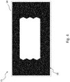
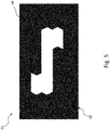
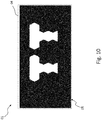
- Scalability Smaller edge lengths increase the resolution, especially for applications such as information symbols, letters, lettering, logos that can be marked ( Fig. 4 , Fig. 5 , Fig. 6 , Fig. 7 , Fig. 8 . Fig. 9 , Fig. 10 ). Larger edge lengths reduce the control costs, especially for applications with multiple function signatures ( Fig. 8 , Fig. 9 , Fig. 10 ).
- the number of pixels 03 of the pixel field 04 is also scalable and only depends on the available installation space and the control.
- Bi-function By using more powerful LEDs, all pixels 03 of the pixel field or even only parts of it can be operated to implement a brake light function or, for example, a repeat flashing light function to indicate the direction of travel. Operation with multi-color LEDs is also possible, so that, for example, the tail light function and the direction indicator can be combined with red and yellow light colors for the various light functions.
- the invention Compared to display and OLED solutions, the invention relies on proven materials and processes.
- the lighting means 01 and a vehicle light equipped with it can provide additional information that can be recognized from outside the vehicle light, for example in FIG Fig. 8 , Fig. 9 , Fig. 10 shown.
- a light signature like in Fig. 9 can be used to indicate a particularly low-emission operation (LO like LOW EMISSION) from outside.
- LO particularly low-emission operation
- an internal combustion engine can also run on fossil fuels through an in Fig. 8 shown light signature (HI like HIGH EMISSION) are displayed outside.
- such light signatures can also be used to show a user of an electric vehicle, for example, the current state of charge before he or she gets into the electric vehicle and / or when he has got out of the electric vehicle again ( Fig. 8 : HI like HIGH; Fig. 9 : LO like LOW) of its power storage.
- the invention can be used commercially in particular in the field of the production of vehicle lights, in particular vehicle lights.
Landscapes
- Engineering & Computer Science (AREA)
- Physics & Mathematics (AREA)
- Mechanical Engineering (AREA)
- Optics & Photonics (AREA)
- General Engineering & Computer Science (AREA)
- Microelectronics & Electronic Packaging (AREA)
- General Physics & Mathematics (AREA)
- Theoretical Computer Science (AREA)
- Non-Portable Lighting Devices Or Systems Thereof (AREA)
Priority Applications (2)
| Application Number | Priority Date | Filing Date | Title |
|---|---|---|---|
| SI201930766T SI3733453T1 (sl) | 2019-05-02 | 2019-05-02 | Luč za vozilo s svetilnim sredstvom |
| EP19172364.2A EP3733453B1 (fr) | 2019-05-02 | 2019-05-02 | Feu de véhicule le comprenant un moyen d'éclairage |
Applications Claiming Priority (1)
| Application Number | Priority Date | Filing Date | Title |
|---|---|---|---|
| EP19172364.2A EP3733453B1 (fr) | 2019-05-02 | 2019-05-02 | Feu de véhicule le comprenant un moyen d'éclairage |
Publications (2)
| Publication Number | Publication Date |
|---|---|
| EP3733453A1 true EP3733453A1 (fr) | 2020-11-04 |
| EP3733453B1 EP3733453B1 (fr) | 2024-04-10 |
Family
ID=66379834
Family Applications (1)
| Application Number | Title | Priority Date | Filing Date |
|---|---|---|---|
| EP19172364.2A Active EP3733453B1 (fr) | 2019-05-02 | 2019-05-02 | Feu de véhicule le comprenant un moyen d'éclairage |
Country Status (2)
| Country | Link |
|---|---|
| EP (1) | EP3733453B1 (fr) |
| SI (1) | SI3733453T1 (fr) |
Citations (9)
| Publication number | Priority date | Publication date | Assignee | Title |
|---|---|---|---|---|
| US4733335A (en) * | 1984-12-28 | 1988-03-22 | Koito Manufacturing Co., Ltd. | Vehicular lamp |
| JPH0968934A (ja) * | 1995-09-01 | 1997-03-11 | Nec Eng Ltd | 表示モジュール |
| US20100039830A1 (en) * | 2008-08-18 | 2010-02-18 | The Hong Kong Polytechnic University | LED automotive tail lamp set |
| US20100331929A1 (en) * | 2008-02-28 | 2010-12-30 | Koninklijke Philips Electronics N.V. | Apparatus for spreading light from multiple sources to eliminate visible boundaries therebetween, light therapy devices including such apparatus, and methods |
| DE102011012297A1 (de) * | 2011-02-24 | 2012-08-30 | Osram Opto Semiconductors Gmbh | Beleuchtungsvorrichtung |
| EP2503222A1 (fr) | 2011-03-15 | 2012-09-26 | Odelo GmbH | Lampe de véhicule automobile et son procédé de fonctionnement |
| CN105179962A (zh) * | 2015-08-10 | 2015-12-23 | 广州市多普光电科技有限公司 | 一种柱状多面体矩阵led光源 |
| GB2554103A (en) * | 2016-09-20 | 2018-03-28 | Truck Lite Europe Ltd | Vehicle lamp |
| DE102018208822A1 (de) * | 2017-06-08 | 2018-12-13 | Seat, S.A. | Leuchtvorrichtung für ein Fahrzeug und zugehörige Heckklappe |
Family Cites Families (1)
| Publication number | Priority date | Publication date | Assignee | Title |
|---|---|---|---|---|
| DE102007033438B4 (de) * | 2007-07-18 | 2012-08-09 | Automotive Lighting Reutlingen Gmbh | Leuchte für Kraftfahrzeuge |
-
2019
- 2019-05-02 EP EP19172364.2A patent/EP3733453B1/fr active Active
- 2019-05-02 SI SI201930766T patent/SI3733453T1/sl unknown
Patent Citations (9)
| Publication number | Priority date | Publication date | Assignee | Title |
|---|---|---|---|---|
| US4733335A (en) * | 1984-12-28 | 1988-03-22 | Koito Manufacturing Co., Ltd. | Vehicular lamp |
| JPH0968934A (ja) * | 1995-09-01 | 1997-03-11 | Nec Eng Ltd | 表示モジュール |
| US20100331929A1 (en) * | 2008-02-28 | 2010-12-30 | Koninklijke Philips Electronics N.V. | Apparatus for spreading light from multiple sources to eliminate visible boundaries therebetween, light therapy devices including such apparatus, and methods |
| US20100039830A1 (en) * | 2008-08-18 | 2010-02-18 | The Hong Kong Polytechnic University | LED automotive tail lamp set |
| DE102011012297A1 (de) * | 2011-02-24 | 2012-08-30 | Osram Opto Semiconductors Gmbh | Beleuchtungsvorrichtung |
| EP2503222A1 (fr) | 2011-03-15 | 2012-09-26 | Odelo GmbH | Lampe de véhicule automobile et son procédé de fonctionnement |
| CN105179962A (zh) * | 2015-08-10 | 2015-12-23 | 广州市多普光电科技有限公司 | 一种柱状多面体矩阵led光源 |
| GB2554103A (en) * | 2016-09-20 | 2018-03-28 | Truck Lite Europe Ltd | Vehicle lamp |
| DE102018208822A1 (de) * | 2017-06-08 | 2018-12-13 | Seat, S.A. | Leuchtvorrichtung für ein Fahrzeug und zugehörige Heckklappe |
Also Published As
| Publication number | Publication date |
|---|---|
| SI3733453T1 (sl) | 2024-07-31 |
| EP3733453B1 (fr) | 2024-04-10 |
Similar Documents
| Publication | Publication Date | Title |
|---|---|---|
| DE10025810B4 (de) | Leuchteneinheit, insbesondere für Außenrückblickspiegel von Fahrzeugen, vorzugsweise von Kraftfahrzeugen | |
| DE102013223717B4 (de) | Kraftfahrzeugbeleuchtungseinrichtung mit zwei oder mehr in die gleiche Richtung strahlenden und in Hauptlichtaustrittsrichtung aufeinanderfolgend angeordneten OLEDs | |
| WO2020114969A1 (fr) | Système d'emblème pour véhicule à moteur | |
| DE102021129672A1 (de) | Beleuchtungsvorrichtung für ein Kraftfahrzeug | |
| EP1523431B1 (fr) | Feu pour vehicules automobiles | |
| DE202015100207U1 (de) | Leuchtmittel und hiermit ausgestattete Fahrzeugleuchte | |
| DE102021122264A1 (de) | Beleuchtungsvorrichtung für ein Fahrzeug | |
| DE102013008192A1 (de) | Beleuchtungsvorrichtung, insbesondere für ein Kraftfahrzeug | |
| DE102013217848A1 (de) | Signalleuchte für ein Kraftfahrzeug | |
| DE102017214656A1 (de) | Scheinwerfer für ein Kraftfahrzeug sowie Verfahren zum Betreiben eines Scheinwerfers | |
| DE202014101538U1 (de) | Kraftfahrzeugleuchte | |
| WO2020104126A1 (fr) | Feu pour véhicule à moteur | |
| DE202018106219U1 (de) | Optikelementeanordnung, Leuchtmittel umfassend eine solche Optikelementeanordnung, sowie mit einem entsprechenden Leuchtmittel ausgestattete Fahrzeugleuchte | |
| EP3788298B1 (fr) | Module d'éclairage de véhicule à moteur | |
| DE102010032946A1 (de) | Kraftfahrzeug mit einem Innenraum, in dem eine Beleuchtungseinrichtung angeordnet ist | |
| DE202020000304U1 (de) | Fahrzeug-Karosseriebauteil | |
| DE102017127925B4 (de) | Leuchtvorrichtung, insbesondere eine Signalleuchte, für Kraftfahrzeuge | |
| EP3466756B1 (fr) | Conduit de lumière en cascade pouvant être animé | |
| DE102022126896A1 (de) | Beleuchtungsvorrichtung für ein Kraftfahrzeug | |
| DE102013225798B4 (de) | Außenspiegelanordnung mit optischer Anzeige | |
| EP3733453B1 (fr) | Feu de véhicule le comprenant un moyen d'éclairage | |
| DE102022134044A1 (de) | Beleuchtungsvorrichtung für ein Kraftfahrzeug | |
| EP2955063A1 (fr) | Lampe de véhicule automobile | |
| EP3553371A1 (fr) | Élément lumineux pour lampes de véhicule automobile comprenant un guide de lumière en forme de plaque et véhicule automobile équipé d'un tel élément lumineux | |
| EP3677831A1 (fr) | Lampe pour véhicule et procédé de génération d'une surface lumineuse minimale dans une fonction d'éclairage d'une lampe pour véhicule |
Legal Events
| Date | Code | Title | Description |
|---|---|---|---|
| PUAI | Public reference made under article 153(3) epc to a published international application that has entered the european phase |
Free format text: ORIGINAL CODE: 0009012 |
|
| STAA | Information on the status of an ep patent application or granted ep patent |
Free format text: STATUS: REQUEST FOR EXAMINATION WAS MADE |
|
| 17P | Request for examination filed |
Effective date: 20200130 |
|
| AK | Designated contracting states |
Kind code of ref document: A1 Designated state(s): AL AT BE BG CH CY CZ DE DK EE ES FI FR GB GR HR HU IE IS IT LI LT LU LV MC MK MT NL NO PL PT RO RS SE SI SK SM TR |
|
| AX | Request for extension of the european patent |
Extension state: BA ME |
|
| STAA | Information on the status of an ep patent application or granted ep patent |
Free format text: STATUS: EXAMINATION IS IN PROGRESS |
|
| 17Q | First examination report despatched |
Effective date: 20220620 |
|
| RIC1 | Information provided on ipc code assigned before grant |
Ipc: H01L 33/58 20100101ALI20231017BHEP Ipc: F21Y 105/10 20160101ALI20231017BHEP Ipc: G02B 19/00 20060101ALI20231017BHEP Ipc: F21V 8/00 20060101ALI20231017BHEP Ipc: H01L 25/075 20060101ALI20231017BHEP Ipc: F21S 43/40 20180101ALI20231017BHEP Ipc: G09F 9/33 20060101ALI20231017BHEP Ipc: G09F 21/04 20060101ALI20231017BHEP Ipc: G09F 9/30 20060101ALI20231017BHEP Ipc: B60Q 1/50 20060101ALI20231017BHEP Ipc: F21S 43/31 20180101ALI20231017BHEP Ipc: F21S 43/20 20180101ALI20231017BHEP Ipc: F21S 43/14 20180101ALI20231017BHEP Ipc: B60Q 1/26 20060101AFI20231017BHEP |
|
| GRAP | Despatch of communication of intention to grant a patent |
Free format text: ORIGINAL CODE: EPIDOSNIGR1 |
|
| STAA | Information on the status of an ep patent application or granted ep patent |
Free format text: STATUS: GRANT OF PATENT IS INTENDED |
|
| INTG | Intention to grant announced |
Effective date: 20231130 |
|
| GRAS | Grant fee paid |
Free format text: ORIGINAL CODE: EPIDOSNIGR3 |
|
| GRAA | (expected) grant |
Free format text: ORIGINAL CODE: 0009210 |
|
| STAA | Information on the status of an ep patent application or granted ep patent |
Free format text: STATUS: THE PATENT HAS BEEN GRANTED |
|
| AK | Designated contracting states |
Kind code of ref document: B1 Designated state(s): AL AT BE BG CH CY CZ DE DK EE ES FI FR GB GR HR HU IE IS IT LI LT LU LV MC MK MT NL NO PL PT RO RS SE SI SK SM TR |
|
| REG | Reference to a national code |
Ref country code: GB Ref legal event code: FG4D Free format text: NOT ENGLISH |
|
| REG | Reference to a national code |
Ref country code: CH Ref legal event code: EP |
|
| REG | Reference to a national code |
Ref country code: DE Ref legal event code: R096 Ref document number: 502019010999 Country of ref document: DE |
|
| REG | Reference to a national code |
Ref country code: IE Ref legal event code: FG4D Free format text: LANGUAGE OF EP DOCUMENT: GERMAN |
|
| REG | Reference to a national code |
Ref country code: LT Ref legal event code: MG9D |
|
| REG | Reference to a national code |
Ref country code: NL Ref legal event code: MP Effective date: 20240410 |
|
| PG25 | Lapsed in a contracting state [announced via postgrant information from national office to epo] |
Ref country code: NL Free format text: LAPSE BECAUSE OF FAILURE TO SUBMIT A TRANSLATION OF THE DESCRIPTION OR TO PAY THE FEE WITHIN THE PRESCRIBED TIME-LIMIT Effective date: 20240410 |
|
| PG25 | Lapsed in a contracting state [announced via postgrant information from national office to epo] |
Ref country code: NL Free format text: LAPSE BECAUSE OF FAILURE TO SUBMIT A TRANSLATION OF THE DESCRIPTION OR TO PAY THE FEE WITHIN THE PRESCRIBED TIME-LIMIT Effective date: 20240410 |
|
| PG25 | Lapsed in a contracting state [announced via postgrant information from national office to epo] |
Ref country code: IS Free format text: LAPSE BECAUSE OF FAILURE TO SUBMIT A TRANSLATION OF THE DESCRIPTION OR TO PAY THE FEE WITHIN THE PRESCRIBED TIME-LIMIT Effective date: 20240810 |
|
| PG25 | Lapsed in a contracting state [announced via postgrant information from national office to epo] |
Ref country code: BG Free format text: LAPSE BECAUSE OF FAILURE TO SUBMIT A TRANSLATION OF THE DESCRIPTION OR TO PAY THE FEE WITHIN THE PRESCRIBED TIME-LIMIT Effective date: 20240410 |
|
| PG25 | Lapsed in a contracting state [announced via postgrant information from national office to epo] |
Ref country code: FI Free format text: LAPSE BECAUSE OF FAILURE TO SUBMIT A TRANSLATION OF THE DESCRIPTION OR TO PAY THE FEE WITHIN THE PRESCRIBED TIME-LIMIT Effective date: 20240410 Ref country code: HR Free format text: LAPSE BECAUSE OF FAILURE TO SUBMIT A TRANSLATION OF THE DESCRIPTION OR TO PAY THE FEE WITHIN THE PRESCRIBED TIME-LIMIT Effective date: 20240410 |
|
| PG25 | Lapsed in a contracting state [announced via postgrant information from national office to epo] |
Ref country code: GR Free format text: LAPSE BECAUSE OF FAILURE TO SUBMIT A TRANSLATION OF THE DESCRIPTION OR TO PAY THE FEE WITHIN THE PRESCRIBED TIME-LIMIT Effective date: 20240711 |
|
| PG25 | Lapsed in a contracting state [announced via postgrant information from national office to epo] |
Ref country code: PT Free format text: LAPSE BECAUSE OF FAILURE TO SUBMIT A TRANSLATION OF THE DESCRIPTION OR TO PAY THE FEE WITHIN THE PRESCRIBED TIME-LIMIT Effective date: 20240812 |
|
| PG25 | Lapsed in a contracting state [announced via postgrant information from national office to epo] |
Ref country code: ES Free format text: LAPSE BECAUSE OF FAILURE TO SUBMIT A TRANSLATION OF THE DESCRIPTION OR TO PAY THE FEE WITHIN THE PRESCRIBED TIME-LIMIT Effective date: 20240410 |
|
| PG25 | Lapsed in a contracting state [announced via postgrant information from national office to epo] |
Ref country code: PL Free format text: LAPSE BECAUSE OF FAILURE TO SUBMIT A TRANSLATION OF THE DESCRIPTION OR TO PAY THE FEE WITHIN THE PRESCRIBED TIME-LIMIT Effective date: 20240410 |
|
| PG25 | Lapsed in a contracting state [announced via postgrant information from national office to epo] |
Ref country code: LV Free format text: LAPSE BECAUSE OF FAILURE TO SUBMIT A TRANSLATION OF THE DESCRIPTION OR TO PAY THE FEE WITHIN THE PRESCRIBED TIME-LIMIT Effective date: 20240410 |
|
| PG25 | Lapsed in a contracting state [announced via postgrant information from national office to epo] |
Ref country code: PT Free format text: LAPSE BECAUSE OF FAILURE TO SUBMIT A TRANSLATION OF THE DESCRIPTION OR TO PAY THE FEE WITHIN THE PRESCRIBED TIME-LIMIT Effective date: 20240812 Ref country code: PL Free format text: LAPSE BECAUSE OF FAILURE TO SUBMIT A TRANSLATION OF THE DESCRIPTION OR TO PAY THE FEE WITHIN THE PRESCRIBED TIME-LIMIT Effective date: 20240410 Ref country code: NO Free format text: LAPSE BECAUSE OF FAILURE TO SUBMIT A TRANSLATION OF THE DESCRIPTION OR TO PAY THE FEE WITHIN THE PRESCRIBED TIME-LIMIT Effective date: 20240710 Ref country code: LV Free format text: LAPSE BECAUSE OF FAILURE TO SUBMIT A TRANSLATION OF THE DESCRIPTION OR TO PAY THE FEE WITHIN THE PRESCRIBED TIME-LIMIT Effective date: 20240410 Ref country code: IS Free format text: LAPSE BECAUSE OF FAILURE TO SUBMIT A TRANSLATION OF THE DESCRIPTION OR TO PAY THE FEE WITHIN THE PRESCRIBED TIME-LIMIT Effective date: 20240810 Ref country code: HR Free format text: LAPSE BECAUSE OF FAILURE TO SUBMIT A TRANSLATION OF THE DESCRIPTION OR TO PAY THE FEE WITHIN THE PRESCRIBED TIME-LIMIT Effective date: 20240410 Ref country code: GR Free format text: LAPSE BECAUSE OF FAILURE TO SUBMIT A TRANSLATION OF THE DESCRIPTION OR TO PAY THE FEE WITHIN THE PRESCRIBED TIME-LIMIT Effective date: 20240711 Ref country code: FI Free format text: LAPSE BECAUSE OF FAILURE TO SUBMIT A TRANSLATION OF THE DESCRIPTION OR TO PAY THE FEE WITHIN THE PRESCRIBED TIME-LIMIT Effective date: 20240410 Ref country code: ES Free format text: LAPSE BECAUSE OF FAILURE TO SUBMIT A TRANSLATION OF THE DESCRIPTION OR TO PAY THE FEE WITHIN THE PRESCRIBED TIME-LIMIT Effective date: 20240410 Ref country code: BG Free format text: LAPSE BECAUSE OF FAILURE TO SUBMIT A TRANSLATION OF THE DESCRIPTION OR TO PAY THE FEE WITHIN THE PRESCRIBED TIME-LIMIT Effective date: 20240410 Ref country code: RS Free format text: LAPSE BECAUSE OF FAILURE TO SUBMIT A TRANSLATION OF THE DESCRIPTION OR TO PAY THE FEE WITHIN THE PRESCRIBED TIME-LIMIT Effective date: 20240710 |
|
| REG | Reference to a national code |
Ref country code: DE Ref legal event code: R082 Ref document number: 502019010999 Country of ref document: DE Representative=s name: BENNINGER, JOHANNES, DIPL.-ING., DE |
|
| REG | Reference to a national code |
Ref country code: CH Ref legal event code: PL |
|
| REG | Reference to a national code |
Ref country code: DE Ref legal event code: R097 Ref document number: 502019010999 Country of ref document: DE |
|
| PG25 | Lapsed in a contracting state [announced via postgrant information from national office to epo] |
Ref country code: DK Free format text: LAPSE BECAUSE OF FAILURE TO SUBMIT A TRANSLATION OF THE DESCRIPTION OR TO PAY THE FEE WITHIN THE PRESCRIBED TIME-LIMIT Effective date: 20240410 |
|
| PG25 | Lapsed in a contracting state [announced via postgrant information from national office to epo] |
Ref country code: LU Free format text: LAPSE BECAUSE OF NON-PAYMENT OF DUE FEES Effective date: 20240502 |
|
| PG25 | Lapsed in a contracting state [announced via postgrant information from national office to epo] |
Ref country code: EE Free format text: LAPSE BECAUSE OF FAILURE TO SUBMIT A TRANSLATION OF THE DESCRIPTION OR TO PAY THE FEE WITHIN THE PRESCRIBED TIME-LIMIT Effective date: 20240410 |
|
| PG25 | Lapsed in a contracting state [announced via postgrant information from national office to epo] |
Ref country code: CZ Free format text: LAPSE BECAUSE OF FAILURE TO SUBMIT A TRANSLATION OF THE DESCRIPTION OR TO PAY THE FEE WITHIN THE PRESCRIBED TIME-LIMIT Effective date: 20240410 |
|
| PG25 | Lapsed in a contracting state [announced via postgrant information from national office to epo] |
Ref country code: SK Free format text: LAPSE BECAUSE OF FAILURE TO SUBMIT A TRANSLATION OF THE DESCRIPTION OR TO PAY THE FEE WITHIN THE PRESCRIBED TIME-LIMIT Effective date: 20240410 Ref country code: RO Free format text: LAPSE BECAUSE OF FAILURE TO SUBMIT A TRANSLATION OF THE DESCRIPTION OR TO PAY THE FEE WITHIN THE PRESCRIBED TIME-LIMIT Effective date: 20240410 |
|
| PG25 | Lapsed in a contracting state [announced via postgrant information from national office to epo] |
Ref country code: SM Free format text: LAPSE BECAUSE OF FAILURE TO SUBMIT A TRANSLATION OF THE DESCRIPTION OR TO PAY THE FEE WITHIN THE PRESCRIBED TIME-LIMIT Effective date: 20240410 |
|
| PG25 | Lapsed in a contracting state [announced via postgrant information from national office to epo] |
Ref country code: SM Free format text: LAPSE BECAUSE OF FAILURE TO SUBMIT A TRANSLATION OF THE DESCRIPTION OR TO PAY THE FEE WITHIN THE PRESCRIBED TIME-LIMIT Effective date: 20240410 Ref country code: SK Free format text: LAPSE BECAUSE OF FAILURE TO SUBMIT A TRANSLATION OF THE DESCRIPTION OR TO PAY THE FEE WITHIN THE PRESCRIBED TIME-LIMIT Effective date: 20240410 Ref country code: RO Free format text: LAPSE BECAUSE OF FAILURE TO SUBMIT A TRANSLATION OF THE DESCRIPTION OR TO PAY THE FEE WITHIN THE PRESCRIBED TIME-LIMIT Effective date: 20240410 Ref country code: LU Free format text: LAPSE BECAUSE OF NON-PAYMENT OF DUE FEES Effective date: 20240502 Ref country code: EE Free format text: LAPSE BECAUSE OF FAILURE TO SUBMIT A TRANSLATION OF THE DESCRIPTION OR TO PAY THE FEE WITHIN THE PRESCRIBED TIME-LIMIT Effective date: 20240410 Ref country code: DK Free format text: LAPSE BECAUSE OF FAILURE TO SUBMIT A TRANSLATION OF THE DESCRIPTION OR TO PAY THE FEE WITHIN THE PRESCRIBED TIME-LIMIT Effective date: 20240410 Ref country code: CZ Free format text: LAPSE BECAUSE OF FAILURE TO SUBMIT A TRANSLATION OF THE DESCRIPTION OR TO PAY THE FEE WITHIN THE PRESCRIBED TIME-LIMIT Effective date: 20240410 Ref country code: CH Free format text: LAPSE BECAUSE OF NON-PAYMENT OF DUE FEES Effective date: 20240531 Ref country code: MC Free format text: LAPSE BECAUSE OF FAILURE TO SUBMIT A TRANSLATION OF THE DESCRIPTION OR TO PAY THE FEE WITHIN THE PRESCRIBED TIME-LIMIT Effective date: 20240410 |
|
| PLBE | No opposition filed within time limit |
Free format text: ORIGINAL CODE: 0009261 |
|
| STAA | Information on the status of an ep patent application or granted ep patent |
Free format text: STATUS: NO OPPOSITION FILED WITHIN TIME LIMIT |
|
| REG | Reference to a national code |
Ref country code: BE Ref legal event code: MM Effective date: 20240531 |
|
| 26N | No opposition filed |
Effective date: 20250113 |
|
| GBPC | Gb: european patent ceased through non-payment of renewal fee |
Effective date: 20240710 |
|
| PG25 | Lapsed in a contracting state [announced via postgrant information from national office to epo] |
Ref country code: IE Free format text: LAPSE BECAUSE OF NON-PAYMENT OF DUE FEES Effective date: 20240502 |
|
| PG25 | Lapsed in a contracting state [announced via postgrant information from national office to epo] |
Ref country code: BE Free format text: LAPSE BECAUSE OF NON-PAYMENT OF DUE FEES Effective date: 20240531 |
|
| PG25 | Lapsed in a contracting state [announced via postgrant information from national office to epo] |
Ref country code: GB Free format text: LAPSE BECAUSE OF NON-PAYMENT OF DUE FEES Effective date: 20240710 |
|
| PGFP | Annual fee paid to national office [announced via postgrant information from national office to epo] |
Ref country code: DE Payment date: 20250618 Year of fee payment: 7 |
|
| REG | Reference to a national code |
Ref country code: AT Ref legal event code: MM01 Ref document number: 1674618 Country of ref document: AT Kind code of ref document: T Effective date: 20240502 |
|
| PGFP | Annual fee paid to national office [announced via postgrant information from national office to epo] |
Ref country code: FR Payment date: 20250620 Year of fee payment: 7 |
|
| PG25 | Lapsed in a contracting state [announced via postgrant information from national office to epo] |
Ref country code: AT Free format text: LAPSE BECAUSE OF NON-PAYMENT OF DUE FEES Effective date: 20240502 |
|
| PGFP | Annual fee paid to national office [announced via postgrant information from national office to epo] |
Ref country code: SI Payment date: 20250605 Year of fee payment: 7 |
|
| PG25 | Lapsed in a contracting state [announced via postgrant information from national office to epo] |
Ref country code: CY Free format text: LAPSE BECAUSE OF FAILURE TO SUBMIT A TRANSLATION OF THE DESCRIPTION OR TO PAY THE FEE WITHIN THE PRESCRIBED TIME-LIMIT; INVALID AB INITIO Effective date: 20190502 |
|
| PG25 | Lapsed in a contracting state [announced via postgrant information from national office to epo] |
Ref country code: HU Free format text: LAPSE BECAUSE OF FAILURE TO SUBMIT A TRANSLATION OF THE DESCRIPTION OR TO PAY THE FEE WITHIN THE PRESCRIBED TIME-LIMIT; INVALID AB INITIO Effective date: 20190502 |
|
| PG25 | Lapsed in a contracting state [announced via postgrant information from national office to epo] |
Ref country code: SE Free format text: LAPSE BECAUSE OF FAILURE TO SUBMIT A TRANSLATION OF THE DESCRIPTION OR TO PAY THE FEE WITHIN THE PRESCRIBED TIME-LIMIT Effective date: 20240410 |
|
| PGFP | Annual fee paid to national office [announced via postgrant information from national office to epo] |
Ref country code: IT Payment date: 20250624 Year of fee payment: 7 |