EP3733491B1 - Stromversorgungsstruktur einer aufbewahrungsbox für sattelfahrzeuge - Google Patents
Stromversorgungsstruktur einer aufbewahrungsbox für sattelfahrzeuge Download PDFInfo
- Publication number
- EP3733491B1 EP3733491B1 EP18894890.5A EP18894890A EP3733491B1 EP 3733491 B1 EP3733491 B1 EP 3733491B1 EP 18894890 A EP18894890 A EP 18894890A EP 3733491 B1 EP3733491 B1 EP 3733491B1
- Authority
- EP
- European Patent Office
- Prior art keywords
- storage box
- stopper
- receiving
- side terminal
- carrier
- Prior art date
- Legal status (The legal status is an assumption and is not a legal conclusion. Google has not performed a legal analysis and makes no representation as to the accuracy of the status listed.)
- Active
Links
Images








Classifications
-
- B—PERFORMING OPERATIONS; TRANSPORTING
- B62—LAND VEHICLES FOR TRAVELLING OTHERWISE THAN ON RAILS
- B62J—CYCLE SADDLES OR SEATS; AUXILIARY DEVICES OR ACCESSORIES SPECIALLY ADAPTED TO CYCLES AND NOT OTHERWISE PROVIDED FOR, e.g. ARTICLE CARRIERS OR CYCLE PROTECTORS
- B62J9/00—Containers specially adapted for cycles, e.g. panniers or saddle bags
- B62J9/20—Containers specially adapted for cycles, e.g. panniers or saddle bags attached to the cycle as accessories
- B62J9/24—Containers specially adapted for cycles, e.g. panniers or saddle bags attached to the cycle as accessories on specially adapted racks, e.g. for top or side cases
-
- B—PERFORMING OPERATIONS; TRANSPORTING
- B62—LAND VEHICLES FOR TRAVELLING OTHERWISE THAN ON RAILS
- B62H—CYCLE STANDS; SUPPORTS OR HOLDERS FOR PARKING OR STORING CYCLES; APPLIANCES PREVENTING OR INDICATING UNAUTHORIZED USE OR THEFT OF CYCLES; LOCKS INTEGRAL WITH CYCLES; DEVICES FOR LEARNING TO RIDE CYCLES
- B62H5/00—Appliances preventing or indicating unauthorised use or theft of cycles; Locks integral with cycles
- B62H5/001—Preventing theft of parts or accessories used on cycles, e.g. lamp, dynamo
-
- B—PERFORMING OPERATIONS; TRANSPORTING
- B62—LAND VEHICLES FOR TRAVELLING OTHERWISE THAN ON RAILS
- B62J—CYCLE SADDLES OR SEATS; AUXILIARY DEVICES OR ACCESSORIES SPECIALLY ADAPTED TO CYCLES AND NOT OTHERWISE PROVIDED FOR, e.g. ARTICLE CARRIERS OR CYCLE PROTECTORS
- B62J45/00—Electrical equipment arrangements specially adapted for use as accessories on cycles, not otherwise provided for
-
- B—PERFORMING OPERATIONS; TRANSPORTING
- B62—LAND VEHICLES FOR TRAVELLING OTHERWISE THAN ON RAILS
- B62J—CYCLE SADDLES OR SEATS; AUXILIARY DEVICES OR ACCESSORIES SPECIALLY ADAPTED TO CYCLES AND NOT OTHERWISE PROVIDED FOR, e.g. ARTICLE CARRIERS OR CYCLE PROTECTORS
- B62J6/00—Arrangement of optical signalling or lighting devices on cycles; Mounting or supporting thereof; Circuits therefor
- B62J6/04—Rear lights
-
- B—PERFORMING OPERATIONS; TRANSPORTING
- B62—LAND VEHICLES FOR TRAVELLING OTHERWISE THAN ON RAILS
- B62J—CYCLE SADDLES OR SEATS; AUXILIARY DEVICES OR ACCESSORIES SPECIALLY ADAPTED TO CYCLES AND NOT OTHERWISE PROVIDED FOR, e.g. ARTICLE CARRIERS OR CYCLE PROTECTORS
- B62J7/00—Luggage carriers
- B62J7/02—Luggage carriers characterised by the arrangement thereof on cycles
- B62J7/04—Luggage carriers characterised by the arrangement thereof on cycles arranged above or behind the rear wheel
-
- B—PERFORMING OPERATIONS; TRANSPORTING
- B62—LAND VEHICLES FOR TRAVELLING OTHERWISE THAN ON RAILS
- B62J—CYCLE SADDLES OR SEATS; AUXILIARY DEVICES OR ACCESSORIES SPECIALLY ADAPTED TO CYCLES AND NOT OTHERWISE PROVIDED FOR, e.g. ARTICLE CARRIERS OR CYCLE PROTECTORS
- B62J9/00—Containers specially adapted for cycles, e.g. panniers or saddle bags
- B62J9/20—Containers specially adapted for cycles, e.g. panniers or saddle bags attached to the cycle as accessories
- B62J9/23—Containers specially adapted for cycles, e.g. panniers or saddle bags attached to the cycle as accessories above or alongside the rear wheel
-
- B—PERFORMING OPERATIONS; TRANSPORTING
- B62—LAND VEHICLES FOR TRAVELLING OTHERWISE THAN ON RAILS
- B62J—CYCLE SADDLES OR SEATS; AUXILIARY DEVICES OR ACCESSORIES SPECIALLY ADAPTED TO CYCLES AND NOT OTHERWISE PROVIDED FOR, e.g. ARTICLE CARRIERS OR CYCLE PROTECTORS
- B62J9/00—Containers specially adapted for cycles, e.g. panniers or saddle bags
- B62J9/20—Containers specially adapted for cycles, e.g. panniers or saddle bags attached to the cycle as accessories
- B62J9/26—Containers specially adapted for cycles, e.g. panniers or saddle bags attached to the cycle as accessories to the saddle, e.g. saddle bags
-
- B—PERFORMING OPERATIONS; TRANSPORTING
- B62—LAND VEHICLES FOR TRAVELLING OTHERWISE THAN ON RAILS
- B62J—CYCLE SADDLES OR SEATS; AUXILIARY DEVICES OR ACCESSORIES SPECIALLY ADAPTED TO CYCLES AND NOT OTHERWISE PROVIDED FOR, e.g. ARTICLE CARRIERS OR CYCLE PROTECTORS
- B62J9/00—Containers specially adapted for cycles, e.g. panniers or saddle bags
- B62J9/20—Containers specially adapted for cycles, e.g. panniers or saddle bags attached to the cycle as accessories
- B62J9/27—Containers specially adapted for cycles, e.g. panniers or saddle bags attached to the cycle as accessories characterised by mounting arrangements, e.g. quick release arrangements
-
- B—PERFORMING OPERATIONS; TRANSPORTING
- B62—LAND VEHICLES FOR TRAVELLING OTHERWISE THAN ON RAILS
- B62J—CYCLE SADDLES OR SEATS; AUXILIARY DEVICES OR ACCESSORIES SPECIALLY ADAPTED TO CYCLES AND NOT OTHERWISE PROVIDED FOR, e.g. ARTICLE CARRIERS OR CYCLE PROTECTORS
- B62J11/00—Supporting arrangements specially adapted for fastening specific devices to cycles, e.g. supports for attaching maps
- B62J11/10—Supporting arrangements specially adapted for fastening specific devices to cycles, e.g. supports for attaching maps for mechanical cables, hoses, pipes or electric wires, e.g. cable guides
Definitions
- the present invention relates to a storage box power supply structure for a saddled vehicle.
- a storage box power supply structure for a saddled vehicle including a storage box having electrical components therein and a carrier configured to detachably mount the storage box on a vehicle body is disclosed (for example, see JP 2016-68766 A ). Since the storage box is attached to the carrier, a carrier-side connector and a storage box-side connector are connected, and electric power can be supplied to the electrical component from a battery of a vehicle.
- EP 0882 644 A2 shows a storage box power supply structure for a saddled vehicle, comprising: a storage box; a carrier provided on a rear section of a vehicle and configured to detachably mount the storage box on a vehicle body; a stopper configured to position the storage box on the carrier; a stopper receiving section configured to receive the stopper; a stopper-side terminal provided on the stopper itself and configured to supply electric power to an electrical component; and a receiving-side terminal provided on the stopper receiving section itself, connected to the stopper-side terminal when the storage box is mounted on the carrier and configured to abut against the stopper-side terminal.
- EP 27380 73 A1 shows a storage box power supply structure for a saddled vehicle, comprising: a storage box; a carrier provided on a vehicle and configured to detachably mount the storage box on a vehicle body; a stopper configured to position the storage box on the carrier; a stopper receiving section configured to receive the stopper; a stopper-side terminal provided on the stopper itself and configured to supply electric power to an electrical component; and a receiving-side terminal provided on the stopper receiving section itself, connected to the stopper-side terminal when the storage box is mounted on the carrier and configured to abut against the stopper-side terminal.
- the plurality of receiving-side terminals (80) are provided at intervals in a vehicle width direction, and the plurality of receiving-side terminals (80) are provided in one stopper receiving section.
- JP 2016-68766 A in order to provide a power supply structure, a new power supply part (a box-side connector) is provided on a bottom section (a box-side facing section facing a carrier-side facing section) of a storage box, and it is necessary to greatly change shapes of the storage box and a carrier.
- a new power supply part a box-side connector
- the oxide film occurs on the terminal on the side of the storage box and the terminal on the side of the carrier or foreign substances such as sand bites or the like are adhered thereto, it is desired that self-cleaning can be actively performed according to an operation of attaching and detaching the storage box.
- An aspect of the present invention is directed to providing a storage box power supply structure for a saddled vehicle in which self-cleaning of a power supply structure using a conventional structure is actively performed according to an operation of attaching and detaching a storage box while a novel power supply part is not provided in the storage box.
- the invention provides a storage box power supply structure for a saddled vehicle according to claim 1.
- the storage box power supply structure for a saddled vehicle since the receiving-side terminal provided on the stopper receiving section, connected to the stopper-side terminal when the storage box is mounted on the carrier and configured to rub against the stopper-side terminal is provided, the following effects are exhibited.
- Self-cleaning of the terminal can be performed by friction when the stopper-side terminal and the receiving-side terminal are connected. It is possible to remove an oxide film of the terminal or remove foreign substances such as sand bites or the like through self-cleaning of the terminal.
- the power supply structure is provided on the stopper and the stopper receiving section, there is no need to provide a new power supply part on a bottom section of the storage box, and also there is no need to greatly change shapes of the storage box and the carrier. Accordingly, self-cleaning can be actively performed according to an operation of attaching and detaching the storage box using a power supply structure having a conventional structure without providing a new power supply part on the storage box.
- the stopper-side terminal and the receiving-side terminal face each other in the forward/rearward direction when the storage box is mounted on the carrier, flexibility in the vehicle width direction can be absorbed by the stopper-side terminal and the receiving-side terminal. Accordingly, variations at the connecting position to the terminal can be absorbed. In addition, friction due to vibrations in the contact portion (hereinafter, referred to as "a contact section") between the stopper-side terminal and the receiving-side terminal can be minimized.
- the biasing member configured to bias at least one of the stopper-side terminal and the receiving-side terminal to the other is further provided, the stopper-side terminal and the receiving-side terminal can easily come into contact with each other.
- the stopper-side terminal and the receiving-side terminal since at least one of the stopper-side terminal and the receiving-side terminal includes the bent section that is bent to protrude toward the other, the following effects are exhibited. In comparison with the case in which both of the stopper-side terminal and the receiving-side terminal are formed in a flat plate shape, the stopper-side terminal and the receiving-side terminal can easily come into contact with each other.
- the storage box power supply structure for a saddled vehicle since the plurality of receiving-side terminals are provided at intervals in the vehicle width direction, the following effects are exhibited.
- connection between the stopper-side terminal and the receiving-side terminal can be reliably performed.
- the terminals can be applied for various uses such as a positive electrode terminal, a negative electrode terminal, a terminal for a stop lamp, or the like.
- the partition wall configured to divide the accommodating spaces of the neighboring two receiving-side terminals is further provided, it is possible to prevent the neighboring two receiving-side terminals from coming in contact with each other.
- the storage box power supply structure for a saddled vehicle since at least a part of the protrusion edge of the partition wall is formed along an external form of the receiving-side terminal, it is possible to prevent the partition wall from becoming an obstacle when the stopper is pushed into the stopper receiving section.
- the protrusion edge of the partition wall is inclined to increase a protrusion height as it is separated from the introduction port of the stopper-side terminal, the following effects are exhibited.
- Rigidity of the stopper receiving section can be increased by the partition wall while preventing the partition wall from becoming an obstacle when the stopper is pushed into the stopper receiving section.
- the stopper is provided on the side of the storage box and the stopper receiving section is provided on the side of the carrier, the following effects are exhibited.
- the stopper-side terminal on the side of the storage box and the receiving-side terminal on the side of the carrier are connected, positioning of the terminal can be easily performed.
- the vertical insertion hole that opens upward and downward in the vicinity of the stopper-side terminal is formed in the stopper receiving section, drainage can be performed through the opening of the vertical insertion hole. For example, even when the storage box is mounted on the carrier when it's raining, it is possible to prevent rain water or the like from being collected in the stopper receiving section.
- the lid member swingably provided on the carrier and configured to cover the introduction port of the stopper-side terminal when the storage box is not mounted on the carrier, the stopper receiving section is not exposed to the outside by the lid member. Accordingly, when the storage box is not mounted on the carrier, it is possible to prevent foreign substances such as water, dust, and the like, from entering the stopper receiving section.
- the stopper since the stopper includes the load receiving section configured to receive a load from the stopper receiving section before the stopper-side terminal and the receiving-side terminal are connected when the storage box is mounted on the carrier, it is possible to prevent an excessive load from being applied to the contact section.
- the stopper-side terminal and the receiving-side terminal are configured to be connected by pushing the stopper into the stopper receiving section after the hook is pushed into the hook receiving section, the following effects are exhibited. Since the stopper-side terminal and the receiving-side terminal are connected after they are positioned by the hook and the hook receiving section, the stopper-side terminal and the receiving-side terminal can be easily connected.
- the storage box power supply structure for a saddled vehicle since the pair of stoppers are provided on left and right sides, the following effects are exhibited. Since the storage box and the carrier are positioned on left and right sides with good balance, in comparison with the case in which only one stopper is provided, the stopper-side terminal and the receiving-side terminal can easily come into contact with each other.
- an arrow FR indicates a forward direction with respect to a vehicle
- an arrow LH indicates a leftward direction with respect to the vehicle
- an arrow UP indicates an upward direction with respect to the vehicle.
- reference sign CL indicates a lateral centerline of a vehicle body.
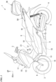
- Fig. 1 shows a unit swing motorcycle 1 as an example of a saddled vehicle.
- the motorcycle 1 includes a front wheel 3 steered by a handle 2, and a rear wheel 4 driven by a power unit 5 including a power source.
- the motorcycle may be simply referred to as "a vehicle.”
- the motorcycle 1 of the embodiment is a scooter type vehicle having step floors 9 on which an occupant sitting on a seat 8 puts his/her legs.
- Steering system parts including the handle 2 and the front wheel 3 are steerably pivoted by a head pipe (not shown) of a front end of a vehicle body frame.
- a head pipe (not shown) of a front end of a vehicle body frame.
- An outer circumference of the vehicle body frame is covered with a vehicle body cover 10.
- reference sign 6 indicates front forks.
- a straddling section 21 having a relatively low height in the vehicle is provided between the handle 2 and the seat 8.
- the step floors 9 are provided on both of left and right sides of the straddling section 21.
- a center tunnel 22 extending forward and rearward to form a convex shape swelling upward is provided between the left and right step floors 9.
- the vehicle body cover 10 includes a front center cover 11 configured to cover a periphery of a head pipe from a forward side, left and right front side covers 12 configured to cover the periphery of the head pipe from a front outward side, a front inner cover 14 configured to cover the periphery of the head pipe from a rearward side and configured to form a front section of the center tunnel 22 and left and right footrests 13, left and right floor front covers 15 continuous with lower rear sides of the left and right front side covers 12, left and right floor side covers 16 continuous with lower downward sides of the left and right floor front covers 15, a center upper cover 17 continuous with a lower rearward side of the front inner cover 14 and configured to form an upper surface of a rear section of the center tunnel 22, left and right center side covers 18 continuous with a rearward side of a lower section of the front inner cover 14 and configured to form a side surface of a rear section of the center tunnel 22, and left and right rear side covers 19 continuous with rearward sides of the center upper cover 17 and the left and right center side covers 18
- a storage box power supply structure 25 configured to supply electric power to electrical components provided in a storage box 30 or the like is provided in the rear section of the vehicle.
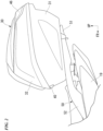
- the storage box power supply structure 25 includes the storage box 30, a carrier 50 configured to detachably mount the storage box 30 on the vehicle body, stoppers 36 (side stoppers 36 shown in Fig. 5 ) configured to position the storage box 30 on the carrier 50, stopper receiving sections 56 (see Fig. 7 ) configured to receive the stoppers 36, stopper-side terminals 70 (see Fig. 13 ) provided on the stoppers 36 and configured to supply electric power to the electrical component 46 (the lid lamp 46 shown in Fig. 2 ), and receiving-side terminals 80 (see Fig. 14 ) provided on the stopper receiving sections 56 and connected to the stopper-side terminals 70 when the storage box 30 is mounted on the carrier 50.
- the storage box 30 is detachably attached to the carrier 50.
- the storage box 30 can store articles such as a helmet and the like.
- the storage box 30 includes a box main body 31 formed in a box shape that opens upward, and a lid 32 provided on an upper section of the box main body 31 to be opened and closed.
- the box main body 31 includes the pair of left and right front hooks 33 disposed on a front lower section of the box main body 31, a rear hook 34 disposed at a center of a rear lower section of the box main body 31, a pair of left and right side stoppers 36 that face each other via the rear hook 34, a pair of left and right leg sections 37 that face each other via the left and right side stoppers 36, and a plurality of (four shown in the drawing) elastic members 38 provided on a lower surface of the box main body 31.
- the pair of left and right front hooks 33 are disposed line-symmetrically with respect to a vehicle body lateral centerline CL as a symmetrical axis. Reinforcement sections of the left and right front hooks 33 are fixed to a front lower section of the box main body 31 by fastening members such as bolts or the like. As shown in Fig. 11 , the left and right front hooks 33 are formed in an L shape extending downward from a front lower section of the box main body 31 and then extending to be bent rearward. When seen in a bottom view of Fig. 4 , rear ends of the left and right front hooks 33 are inclined to be disposed rearward as they go inward in a vehicle width direction.
- the rear hook 34 is movable in conjunction with a pivoting operation of a key (not shown).
- the rear hook 34 is movable between an engaging position and an engagement releasing position with respect to a rear hook receiving section 54 in conjunction with an operation of a rear hook locking mechanism (not shown) in conjunction with a pivoting operation of the key.
- the rear hook 34 is formed in an L shape extending downward from a lower section of the box main body 31 and then extending to be bent rearward.
- the left and right side stoppers 36 and the left and right leg sections 37 protrude downward from a lower surface of the box main body 31.
- a protrusion height of each of the left and right side stoppers 36 is smaller than a protrusion height of each of the left and right leg sections 37.
- the left and right side stoppers 36 function as a load receiving section configured to receive a load in the forward/rearward direction.
- the four elastic members 38 are disposed between the front and rear left and right front hooks 33 and left and right side stoppers 36.
- the four elastic members 38 are disposed at intervals in the forward/rearward direction and the vehicle width direction.
- the elastic members 38 are vibration-proof rubbers.
- a handle 42 is swingably attached to a rear section of the box main body 31.
- the handle 42 In a state in Fig. 5 , the handle 42 is in a receiving state in which the handle 42 is received in a U-shaped groove 31u. In the receiving state, the handle 42 is disposed along a rear surface of the box main body 31.
- the lid 32 is a box-shaped member configured to cover the box main body 31 from above. As shown in Fig. 10 , the lid 32 is swingably attached to a front end portion of the box main body 31 via a rocking shaft 45. The lid 32 can be locked by a lid locking mechanism (not shown).
- the lid lamp 46 serving as an electrical component is provided in a rear section of the lid 32.
- the lid lamp 46 is a light emitting diode (LED).
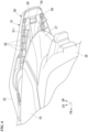
- the lid lamp 46 is connected to the hook-side terminals 70 (see Fig. 13 ) via a cord 47 (see Fig. 3 ) routed on an inner surface of the lid 32.
- a portion 47a (see Fig. 3 ) of the cord 47 close to a front section of the lid 32 is preferably disposed parallel to the rocking shaft 45 (see Fig. 10 ). Accordingly, bending of the cord 47 can be avoided and disconnection thereof can be prevented.
- a portion 47b (see Fig. 3 ) of the cord 47 close to a front section of the box main body 31 is preferably disposed along an inner wall of a corner section of the box main body 31. Accordingly, even when articles such as a helmet and the like are stored in the storage box 30, it is possible to prevent the cord 47 from coming in contact with the articles such as a helmet or the like.
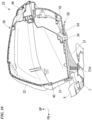
- the carrier 50 is configured to detachably mount the storage box 30 on the vehicle body.
- the carrier 50 includes a carrier main body 51 on which the storage box 30 is mounted, and a pair of left and right grab rails 52 that are grabbed by an occupant.
- the carrier main body 51 and the left and right grab rails 52 are integrally formed of the same member.
- the carrier main body 51 has an external form having a width in the vehicle width direction that is reduced rearward.
- the carrier main body 51 includes the pair of left and right front hook receiving sections 53 (see Fig. 11 ) configured to receive the left and right front hooks 33 (see Fig. 5 ), the rear hook receiving section 54 (see Fig. 10 ) configured to receive the rear hook 34 (see Fig. 5 ), a pair of left and right side insertion holes 56 (see Fig. 12 ) into which the left and right side stoppers 36 (see Fig. 5 ) are inserted, and a seat surface 57 which the elastic members 38 (see Fig. 5 ) abut, when the storage box 30 (see Fig. 2 ) is mounted on the carrier main body 51.
- vertical opening sections 51h that open upward and downward in the vicinity of the front hook receiving sections 53 are provided in the front section of the carrier main body 51.
- the vertical opening sections 51h each have a long hole shape extending to be disposed rearward as it goes inward in the vehicle width direction.
- reference sign 27 designates a tail light
- reference sign 28 designates a rear fender.
- the carrier main body 51 has a pair of left and right opening sections 51i formed in the central section of the carrier main body 51 to open upward and downward, and a front section insertion hole 51m formed in the front section of the carrier main body 51 to open upward and downward.
- the left and right opening sections 51i each have a long hole shape extending forward and rearward.
- the front section insertion hole 51m has a circular shape.
- the front section insertion hole 51m is an insertion hole through which a shaft section of a bolt configured to fix the carrier main body 51 to a rear frame 7 (see Fig. 10 ) is inserted.
- the left and right grab rails 52 extend forward from an outer end portion of the front section of the carrier main body 51 in the vehicle width direction.
- upper edges of the left and right grab rails 52 are inclined to be disposed downward as they go forward.
- inward protrusion sections 52a protruding inward from front end portions of the left and right grab rails 52 in the vehicle width direction are provided on the left and right grab rails 52.
- the inward protrusion sections 52a are fixed to the rear frame 7 (see Fig. 10 ) by fastening members (not shown) such as bolts or the like.
- a plurality of ribs 61 to 66 are provided on a lower section of the carrier 50.
- the plurality of ribs 61 to 66 are a first rib 61 extending forward and rearward to cross a forming section of the front section insertion hole 51m and the rear hook receiving section 54, a second rib 62 extending in the vehicle width direction to cross the forming section of the front section insertion hole 51m and an outer edge of the carrier main body 51 in the vehicle width direction, a third rib 63 extending to cross the left and right front hook receiving sections 53 and the second rib 62, a fourth rib 64 extending to cross forming sections of the stopper receiving sections 56 and the second rib 62, a fifth rib 65 extending to cross from outer edges of the left and right opening sections 51i in the vehicle width direction to an outer edge of the carrier main body 51 in the vehicle width direction, and sixth ribs 66 extending from front lower sections of the left and right grab rails 52 in the vehicle width direction
- the stopper-side terminals 70 are provided on the front sections of the side stoppers 36 (hereinafter, simply referred to as "the stoppers 36").
- the plurality of (in Fig. 13 , two) stopper-side terminals 70 are provided with an interval therebetween in the vehicle width direction.
- the stopper-side terminals 70 are provided on the left and right stoppers 36, respectively.
- the stopper-side terminals 70 extend in the upward/downward direction and each have a plate shape having a thickness in the forward/rearward direction.
- the stopper-side terminals 70 and the receiving-side terminals 80 face each other in the forward/rearward direction when the storage box 30 is mounted on the carrier 50.
- the stoppers 36 When seen in a left side view of Fig. 15(a) , the stoppers 36 each have an external form having a longitudinal width that is reduced downward. Concave escape sections 36a recessed to avoid partition walls 83 when the storage box 30 is mounted on the carrier 50 are provided in the stoppers 36. As shown in Fig. 13 , the two stopper-side terminals 70 are arranged on left and right sides via the concave escape sections 36a.
- the stoppers 36 include load receiving sections 36b configured to receive a load from the stopper receiving sections 56 before the stopper-side terminals 70 and the receiving-side terminals 80 are connected when the storage box 30 is mounted on the carrier 50.
- the load receiving sections 36b are disposed outward from the stopper-side terminals 70 in the vehicle width direction.
- the load receiving sections 36b protrude forward from installation surfaces 36f of the stopper-side terminals 70.
- a height (a thickness) of the stopper-side terminals 70 is smaller than that of protrusion ends of the load receiving sections 36b.
- the stopper-side terminals 70 are disposed further rearward (inward) than the protrusion ends of the load receiving sections 36b of the stoppers 36.
- One end of the cord 47 is connected to the stopper-side terminals 70. Further, the other end of the cord 47 is connected to the lid lamp 46 (see Fig. 5 ).
- the receiving-side terminals 80 are provided on rear sections of vertical walls 56a of the stopper receiving sections 56.
- the plurality of (in Fig. 14(b) , two) receiving-side terminals 80 are provided at an interval in the vehicle width direction.
- the receiving-side terminals 80 are provided in the left and right stopper receiving sections 56, respectively.
- the receiving-side terminals 80 are connected to the stopper-side terminals 70 when the storage box 30 is mounted on the carrier 50.
- the receiving-side terminals 80 are connected to the stopper-side terminals 70 and rub against the stopper-side terminals 70 when the storage box 30 is mounted on the carrier 50.
- the stopper-side terminals 70 and the receiving-side terminals 80 are configured to be connected by pushing the stoppers 36 into the stopper receiving sections 56 after the front hooks 33 are pushed into the hook receiving section 53 (see Fig. 16 ).
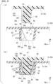
- the receiving-side terminals 80 When seen in a left side view of Fig. 15(b) , the receiving-side terminals 80 include bent sections 80a extending in the upward/downward direction and bent to protrude toward the stopper-side terminals 70. Contact portions between flat surface sections 70a of the stopper-side terminals 70 and the bent sections 80a of the receiving-side terminals 80 become contact sections of the terminals 70 and 80.
- the receiving-side terminals 80 are swingably attached to the vertical walls 56a. Upper end portions of the receiving-side terminals 80 are pivotable around a support shaft (not shown) extending in the vehicle width direction.
- Biasing members 82 configured to bias the receiving-side terminals 80 toward the stopper-side terminals 70 are attached to the receiving-side terminals 80.
- the biasing members 82 are coil springs.
- Portions of the receiving-side terminals 80 opposite to the stopper-side terminals 70 are connected to a battery (not shown) on the side of the vehicle body via the wiring 85.
- Vertical insertion holes 56h that open upward in the vicinity of the receiving-side terminals 80 are provided in the stopper receiving sections 56.
- the vertical insertion holes 56h communicate with introduction ports 56i (hereinafter, referred to as "stopper introduction ports 56i") of the stopper-side terminals 70 in the upward/downward direction.
- the partition walls 83 configured to divide accommodating spaces of the neighboring two receiving-side terminals 80 are provided on the vertical walls 56a of the stopper receiving sections 56.
- the partition walls 83 protrude rearward from the vertical walls 56a and extend upward and downward. Parts of protrusion edges 83a of the partition walls 83 are formed along external forms of the receiving-side terminals 80.
- the protrusion edges 83a of the partition walls 83 are inclined such that a protrusion height increases going away from the introduction ports 56i of the stopper-side terminals 70 (downward).
- the protrusion edges 83a of the partition walls 83 are formed in a linear shape that is inclined to be disposed downward as it goes rearward.
- a protrusion height of the receiving-side terminals 80 is smaller than that of the protrusion edges 83a of the partition walls 83.
- the receiving-side terminals 80 are disposed further forward (inward) than the protrusion edges 83a of the partition walls 83 in the stopper receiving sections 56.
- lid members 90 swingably provided on the carrier 50 and configured to cover the stopper introduction ports 56i when the storage box 30 is not mounted on the carrier 50 may be provided on the stopper receiving sections 56.
- the lid members 90 include rectangular plate-shaped lid main bodies 91 configured to cover the stopper introduction ports 56i, hinge shafts 92 extending in the vehicle width direction and configured to pivotably support the lid main bodies 91, and locking claws 93 protruding from tips of the lid main bodies 91.
- the lid members 90 are normally biased by spring members (not shown) in an arrow K1 direction (see Fig. 15(a) ).
- Claw receiving sections 83c configured to receive the locking claws 93 are provided in upper end portions of the partition walls 83.
- the lid members 90 are pivoted against biasing forces of the spring members in an arrow K2 direction (see Fig. 15(b) ) when the storage box 30 is mounted on the carrier 50.
- escape grooves 83b recessed to avoid the locking claws 93 when the storage box 30 is mounted on the carrier 50 are provided in protrusion ends of the vertical walls 56a.
- the receiving-side terminals 80 (see Fig. 15 ) on the side of the carrier 50 and the stopper-side terminals 70 (see Fig. 15 ) on the side of the storage box 30 are connected to each other.
- the stopper receiving sections 56 receive the stoppers 36 after the front hooks 33 are pushed into the hook receiving section 53 (see Fig. 16 )
- the stopper-side terminals 70 and the receiving-side terminals 80 are connected to each other.
- the receiving-side terminals 80 are pivoted against biasing forces of biasing members 82 in an arrow K3 direction while being connected to the stopper-side terminals 70. Accordingly, electric power can be supplied to the electrical component on the side of the lid 32 (the lid lamp 46 shown in Fig. 5 ) from the battery (not shown) on the side of the vehicle body.
- the storage box 30 can be attached to the carrier 50.
- the storage box 30 can be removed from the carrier 50.
- the storage box power supply structure 25 of the embodiment includes the storage box 30, the carrier 50 configured to detachably mount the storage box 30 on the vehicle body, the stoppers 36 configured to position the storage box 30 on the carrier 50, the stopper receiving sections 56 configured to receive the stoppers 36, the stopper-side terminals 70 provided on the stoppers 36 and configured to supply electric power to the lid lamp 46, and the receiving-side terminals 80 provided on the stopper receiving sections 56, connected to the stopper-side terminals 70 when the storage box 30 is mounted on the carrier 50 and configured to rub against the stopper-side terminals 70.
- the receiving-side terminals 80 provided on the stopper receiving sections 56, connected to the stopper-side terminals 70 when the storage box 30 is mounted on the carrier 50 and configured to rub against the stopper-side terminals 70 are provided, the following effects are exhibited.
- Self-cleaning of the terminals 70 and 80 can be performed by friction when the stopper-side terminals 70 and the receiving-side terminals 80 are connected to each other. It is possible to remove the oxide films of the terminals 70 and 80 through self-cleaning of the terminals 70 and 80 or remove foreign substances such as sand bites or the like.
- the power supply structure is provided on the stopper receiving sections 56, there is no need to provide a novel power supply part on the bottom section of the storage box 30, and also there is no need to greatly change shapes of the storage box 30 and the carrier 50. Accordingly, self-cleaning of a power supply structure using a conventional structure can be actively performed according to an operation of attaching and detaching the storage box 30 while a novel power supply part is not provided in the storage box 30.
- stopper-side terminals 70 and the receiving-side terminals 80 face each other in the forward/rearward direction when the storage box 30 is mounted on the carrier 50, flexibility in the vehicle width direction can be absorbed by the stopper-side terminals 70 and the receiving-side terminals 80. Accordingly, variations at the connecting position to the terminals 70 and 80 can be absorbed. In addition, friction due to vibrations in the contact sections between the stopper-side terminals 70 and the receiving-side terminals 80 can be minimized.
- the biasing members 82 configured to bias the receiving-side terminals 80 toward the stopper-side terminals 70 are further provided, the stopper-side terminals 70 and the receiving-side terminals 80 can easily come into contact with each other.
- the receiving-side terminals 80 include the bent sections 80a that are bent to protrude toward the stopper-side terminals 70, the following effects are exhibited. In comparison with the case in which both of the stopper-side terminals 70 and the receiving-side terminals 80 are formed in a flat plate shape, the stopper-side terminals 70 and the receiving-side terminals 80 can easily come into contact with each other.
- the plurality of receiving-side terminals 80 are provided at an interval in the vehicle width direction, the following effects are exhibited. In comparison with the case in which only one receiving-side terminal 80 is provided, connection of the stopper-side terminals 70 and the receiving-side terminals 80 can be reliably performed. For example, when the plurality of stopper-side terminals 70 corresponding to the plurality of receiving-side terminals 80 are provided, they can be applied to various uses for a positive electrode terminal, a negative electrode terminal, a terminal for a stop lamp, and the like.
- the partition walls 83 configured to divide the accommodating spaces of the neighboring two receiving-side terminals 80 are further provided, it is possible to prevent the neighboring two receiving-side terminals 80 from coming in contact with each other.
- part of the protrusion edges 83a of the partition walls 83 are formed along external forms of the receiving-side terminals 80, it is possible to prevent the partition walls 83 from becoming obstacles when the stoppers 36 are pushed into the stopper receiving sections 56.
- the protrusion edges 83a of the partition walls 83 are inclined to increase a protrusion height as they are separated from the introduction ports 56i of the stopper-side terminals 70, the following effects are exhibited. It is possible for the partition walls 83 to increase rigidity of the stopper receiving sections 56 while the partition walls 83 are prevented from becoming obstacles when the stoppers 36 are pushed into the stopper receiving sections 56.
- the stoppers 36 are provided on the side of the storage box 30 and the stopper receiving sections 56 are provided on the side of the carrier 50, the following effects are exhibited.
- the stopper-side terminals 70 on the side of the storage box 30 and the receiving-side terminals 80 on the side of the carrier 50 are connected to each other, positioning of the terminals 70 and 80 can be easily performed.
- the vertical insertion holes 56h that open upward and downward in the vicinity of the stopper-side terminals 70 are provided in the stopper receiving sections 56, drainage can be performed through openings of the vertical insertion holes 56h.
- the storage box 30 is mounted on the carrier 50 when it's raining, rain water and the like can be prevented from being collected in the stopper receiving sections 56.
- the lid members 90 swingably provided on the carrier 50 and configured to cover the introduction ports 56i of the stopper-side terminals 70 when the storage box 30 is not mounted on the carrier 50 is further provided, the stopper receiving sections 56 are not exposed to the outside by the lid members 90. Accordingly, when the storage box 30 is not mounted on the carrier 50, it is possible to prevent foreign substances such as water, dust, and the like, from entering the stopper receiving sections 56.
- stoppers 36 include the load receiving sections 36b configured to receive a load from the stopper receiving sections 56 before the stopper-side terminals 70 and the receiving-side terminals 80 are connected when the storage box 30 is mounted on the carrier 50, it is possible to prevent an excessive load from being applied to the contact section.
- the stopper-side terminals 70 and the receiving-side terminals 80 are configured to be connected by pushing the stoppers 36 into the stopper receiving sections 56 after the hook 33 are pushed into the hook receiving section 53, the following effects are exhibited. Since the stopper-side terminals 70 and the receiving-side terminals 80 are connected after the hook 33 and the hook receiving section 53 are positioned, the stopper-side terminals 70 and the receiving-side terminals 80 can be easily connected.
- the pair of stoppers 36 are provided on left and right sides, the following effects are exhibited. Since the storage box 30 and the carrier 50 are positioned on left and right sides with good balance, in comparison with the case in which only one stopper 36 is provided, the stopper-side terminals 70 and the receiving-side terminals 80 can easily come into contact with each other.
- the storage box 30 may be provided on a front section of the vehicle or may be provided on a side portion of the vehicle (a side portion of the carrier 50).
- stopper-side terminals 70 are provided on the left and right stoppers 36, respectively, has been exemplarily described in the embodiment, there is no limitation thereto.
- the stopper-side terminals 70 may be provided on only one of the left and right stoppers 36. That is, the stopper-side terminals 70 may be formed on at least one of the left and right stoppers 36.
- the biasing members 82 configured to bias the receiving-side terminals 80 toward the stopper-side terminals 70 has been exemplarily described in the embodiment, there is no limitation thereto.
- the biasing member configured to bias the stopper-side terminals 70 toward the receiving-side terminals 80 may be provided. That is, a biasing member configured to bias at least one of the stopper-side terminals 70 and the receiving-side terminals 80 toward the other may be provided.
- biasing members 82 are the coil springs
- the biasing members 82 may be leaf springs.
- the receiving-side terminals 80 include the bent sections 80a that are bent to protrude toward the stopper-side terminals 70
- the stopper-side terminals 70 may include bent sections that are bent to protrude toward the receiving-side terminals 80. That is, at least one of the stopper-side terminals 70 and the receiving-side terminals 80 may include bent sections that are bent to protrude the other.
- the front hooks 33 each are formed in an L shape extending downward from the front lower section of the box main body 31 and then extending rearward
- the front hooks 33 may be formed in an L shape extending downward from the front lower section of the box main body 31 and then extending rearward.
- the electrical component may be another electrical component such as a USB charger, a solenoid, or the like, or may be other lighting devices than the lid lamp 46.
- a contact portion between a flat surface section 170a (see Fig. 17 ) of a stopper-side terminal 170 and a flat surface section 180a (see Fig. 18 ) of a receiving-side terminal 180 may be a contact section between the terminals 170 and 180.
- reference sign 136b designates load receiving sections that constitute left and right sidewalls of the stoppers 36.
- illustration of the lid members 90 or the like will be omitted.
- the stopper-side terminal 170 may include a longitudinal extension section 171 extending in the forward/rearward direction, and a downward extension section 172 having an L shape extending downward from a front end of the longitudinal extension section 171 to form the flat surface section 170a and then extending rearward.
- the longitudinal extension section 171 is attached to a bottom section of the box main body 31.
- a rear section of the longitudinal extension section 171 is connected to the lid lamp 46 (see Fig. 5 ) via the cord 47.
- the receiving-side terminal 180 may be formed in a C shape (a U shape) having the flat surface section 180a that is able to come in contact with the flat surface section 170a of the downward extension section 172.
- the biasing members 82 configured to bias the receiving-side terminal 180 toward the stopper-side terminal 170 are attached to the receiving-side terminal 180.
- the receiving-side terminals 80 are connected to a battery (not shown) on the side of the vehicle body via the wiring 85.
- the stopper-side terminal 170 and the receiving-side terminal 180 are connected.
- the receiving-side terminal 180 moves against the biasing force of the spring members 82 in an arrow K4 direction while being connected to the stopper-side terminal 170. Accordingly, electric power can be supplied from the battery (not shown) on the side of the vehicle body to the electrical component (the lid lamp 46 shown in Fig. 5 ) on the side of the lid 32.
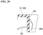
- the receiving-side terminal 80 itself may be constituted by a biasing member such as a coil spring, a leaf spring, or the like. Accordingly, the number of parts can be reduced and reduction in costs can be achieved.
- a receiving-side terminal 280 having a leaf spring shape may be provided.
- the present invention is not limited to the embodiment, and for example, all vehicles on which a driver rides on the vehicle body are included as the saddles vehicle, and in addition to a motorcycle (including a motorized bicycle and a scooter-type vehicle), a three-wheeled vehicle (including a two-front-wheeled and one-rear-wheeled vehicle in addition to one-front-wheeled and two-rear-wheeled vehicle) is also included.
- the present invention may also be applicable to a four-wheeled vehicle such as an automobile or the like, in addition to the motorcycle.
Landscapes
- Engineering & Computer Science (AREA)
- Mechanical Engineering (AREA)
- Battery Mounting, Suspending (AREA)
- Automatic Cycles, And Cycles In General (AREA)
Claims (13)
- Aufbewahrungskasten-Stromversorgungsstruktur für ein Sattelfahrzeug, umfassend:einen Aufbewahrungskasten (30);einen Träger (50), der an einem hinteren Abschnitt eines Fahrzeugs vorgesehen und konfiguriert ist, um den Aufbewahrungskasten (30) an einem Fahrzeugrumpf abnehmbar anzubringen;ein Paar linker und rechter Seitenstopper (36), die so konfiguriert sind, dass sie von einer unteren Seite des Aufbewahrungskastens (30) vorstehen, wobei ein Paar linker und rechter vorderer Haken (33) an einem vorderen unteren Abschnitt des Aufbewahrungskastens (30) angeordnet ist, wobei die linken und rechten Seitenstopper (36) über einen hinteren Haken (34), der an einer Mitte eines hinteren unteren Abschnitts des Aufbewahrungskastens (30) angeordnet ist, einander gegenüberliegen, wobei der hintere Haken (34) zwischen den linken und rechten Seitenstoppern (36) angeordnet ist;ein Paar linker und rechter vorderer Hakenaufnahmeabschnitte (53), die konfiguriert sind, um die linken und rechten vorderen Haken (33) aufzunehmen, wobei die linken und rechten vorderen Hakenaufnahmeabschnitte (53) in einem vorderen Abschnitt des Trägers (50) vorgesehen sind;ein Paar linker und rechter Stopperaufnahmeabschnitte (56), die konfiguriert sind, um das Paar linker und rechter Seitenstopper (36) aufzunehmen, wobei die linken und rechten Stopperaufnahmeabschnitte (56) an einer oberen Seite eines hinteren Abschnitts des Trägers (50) vorgesehen sind;einen stopperseitigen Anschluss (70), der an den linken und rechten Seitenstoppern (36) selbst vorgesehen und konfiguriert ist, um einer elektrischen Komponente (46) elektrischen Strom zuzuführen; undeinen aufnahmeseitigen Anschluss (80), der an den linken und rechten Stopperaufnahmeabschnitten (56) selbst vorgesehen ist, mit dem stopperseitigen Anschluss (70) verbunden ist, wenn der Aufbewahrungskasten (30) an dem Träger (50) angebracht, und konfiguriert ist, um gegen den stopperseitigen Anschluss (70) zu reiben, wobeidie mehreren aufnahmeseitigen Anschlüsse (80) mit Intervallen in Fahrzeugbreitenrichtung vorgesehen sind, wobeidie mehreren aufnahmeseitigen Anschlüsse (80) in einem Stopperaufnahmeabschnitt (56) vorgesehen sind.
- Die Aufbewahrungskasten-Stromversorgungsstruktur für ein Sattelfahrzeug nach Anspruch 1, wobei der stopperseitige Anschluss (70) und der aufnahmeseitige Anschluss (80) in Vorwärts/Rückwärtsrichtung einander gegenüberliegen, wenn der Aufbewahrungskasten (30) an dem Träger (50) angebracht ist.
- Die Aufbewahrungskasten-Stromversorgungsstruktur für ein Sattelfahrzeug nach Anspruch 1 oder 2, die ferner ein Spannelement (82) aufweist, das konfiguriert ist, um zumindest einen des stopperseitigen Anschlusses (70) und des aufnahmeseitigen Anschlusses (80) aufeinander zu zuspannen.
- Die Aufbewahrungskasten-Stromversorgungsstruktur für ein Sattelfahrzeug nach einem der Ansprüche 1 bis 3, wobei zumindest einer des stopperseitigen Anschlusses (70) und des aufnahmeseitigen Anschlusses (80) einen gebogenen Abschnitt (80a) aufweist, der so gebogen ist, dass sie aufeinander zu weisen.
- Die Aufbewahrungskasten-Stromversorgungsstruktur für ein Sattelfahrzeug nach einem der Ansprüche 1 bis 4, die ferner eine Trennwand (83) aufweist, die konfiguriert ist, um die Aufnahmeräume der zwei benachbarten aufnahmeseitigen Anschlüsse (80) zu unterteilen.
- Die Aufbewahrungskasten-Stromversorgungsstruktur für ein Sattelfahrzeug nach Anspruch 5, wobei zumindest ein Teil eines Vorsprungsrands (83a) der Trennwand (83) entlang einer Außenform des aufnahmeseitigen Anschlusses (80) ausgebildet ist.
- Die Aufbewahrungskasten-Stromversorgungsstruktur für ein Sattelfahrzeug nach Anspruch 5 oder 6, wobei der Vorsprungsrand (83a) der Trennwand (83) geneigt ist, um mit zunehmendem Abstand des Vorsprungsrands (83a) von einer Einführöffnung (56i) des stopperseitigen Anschlusses (70) eine Vorsprungshöhe zu vergrößern.
- Die Aufbewahrungskasten-Stromversorgungsstruktur für ein Sattelfahrzeug nach einem der Ansprüche 1 bis 7, wobei ein vertikales Einsetzloch (56h), das sich in der Nähe des stopperseitigen Anschlusses (70) nach oben und unten öffnet, in den linken und rechten Stopperaufnahmeabschnitten (56) ausgebildet ist.
- Die Aufbewahrungskasten-Stromversorgungsstruktur für ein Sattelfahrzeug nach Anspruch 7, die ferner ein Deckelelement (90) aufweist, das auf dem Träger (50) schwenkbar vorgesehen und konfiguriert ist, um die Einführöffnung (56i) des stopperseitigen Anschlusses (70) abzudecken, wenn der Aufbewahrungskasten (30) an dem Träger angebracht ist.
- Die Aufbewahrungskasten-Stromversorgungsstruktur für ein Sattelfahrzeug nach einem der Ansprüche 1 bis 9, wobei die linken und rechten Seitenstopper (36) einen Lastaufnahmeabschnitt (36b) aufweisen, der konfiguriert ist, um eine Last von den linken und rechten Stopperaufnahmeabschnitten (56) aufzunehmen, bevor der stopperseitige Anschluss (70) und der aufnahmeseitige Anschluss (80) verbunden sind, wenn der Aufbewahrungskasten (30) an dem Träger (50) angebracht wird.
- Die Aufbewahrungskasten-Stromversorgungsstruktur für ein Sattelfahrzeug nach einem der Ansprüche 1 bis 10, die ferner aufweist:die linken und rechten vorderen Haken (33), die konfiguriert sind, um den Aufbewahrungskasten (30) mit dem Träger (50) zu verbinden;wobei der stopperseitige Anschluss (70) und der aufnahmeseitige Anschluss (80) konfiguriert sind, um durch Schieben der linken und rechten Seitenstopper (36) in die linken und rechten Stopperaufnahmeabschnitte (56) verbunden zu werden, nachdem die linken und rechten vorderen Haken (33) in die linken und rechten vorderen Hakenaufnahmeabschnitte (53) geschoben sind.
- Die Aufbewahrungskasten-Stromversorgungsstruktur für ein Sattelfahrzeug nach einem der Ansprüche 1 bis 11, die ferner aufweist:ein Paar linker und rechter Beinabschnitte (37) die über die linken und rechten Stopper (36) aufeinander zu weisen,wobei der hintere Haken (34), die linken und rechten Seitenstopper (36) und die linken und rechten Beinabschnitte (37), bei Betrachtung von einer Seite des Fahrzeugs, einander überlappen.
- Die Aufbewahrungskasten-Stromversorgungsstruktur für ein Sattelfahrzeug nach einem der Ansprüche 1 bis 12, die ferner aufweist:ein Paar linker und rechter Beinabschnitte (37), die von der Unterseite des Aufbewahrungskastens (30) nach unten vorstehen,wobei eine Vorsprungshöhe jedes der linken und rechten Beinabschnitte (37) höher ist als eine Vorsprungshöhe jeder der linken und rechten Seitenstopper (36).
Applications Claiming Priority (2)
| Application Number | Priority Date | Filing Date | Title |
|---|---|---|---|
| JP2017254991 | 2017-12-28 | ||
| PCT/JP2018/034429 WO2019130678A1 (ja) | 2017-12-28 | 2018-09-18 | 鞍乗型車両の収納ボックス給電構造 |
Publications (3)
| Publication Number | Publication Date |
|---|---|
| EP3733491A1 EP3733491A1 (de) | 2020-11-04 |
| EP3733491A4 EP3733491A4 (de) | 2021-02-24 |
| EP3733491B1 true EP3733491B1 (de) | 2023-11-22 |
Family
ID=67066947
Family Applications (1)
| Application Number | Title | Priority Date | Filing Date |
|---|---|---|---|
| EP18894890.5A Active EP3733491B1 (de) | 2017-12-28 | 2018-09-18 | Stromversorgungsstruktur einer aufbewahrungsbox für sattelfahrzeuge |
Country Status (4)
| Country | Link |
|---|---|
| US (1) | US11167814B2 (de) |
| EP (1) | EP3733491B1 (de) |
| JP (1) | JP6873277B2 (de) |
| WO (1) | WO2019130678A1 (de) |
Families Citing this family (1)
| Publication number | Priority date | Publication date | Assignee | Title |
|---|---|---|---|---|
| TWI698367B (zh) * | 2019-10-31 | 2020-07-11 | 光陽工業股份有限公司 | 機車的行李箱 |
Family Cites Families (19)
| Publication number | Priority date | Publication date | Assignee | Title |
|---|---|---|---|---|
| CN2141789Y (zh) | 1992-09-10 | 1993-09-08 | 吴式南 | 一种可拆卸车用后置箱装置 |
| FR2703844B1 (fr) | 1993-04-09 | 1995-05-24 | Sepm | Connecteur électrique et plus particulièrement connecteur de charge. |
| JP3662659B2 (ja) * | 1996-02-23 | 2005-06-22 | 朝日電装株式会社 | 圧着摺動スイッチ |
| IT243471Y1 (it) * | 1997-05-30 | 2002-03-04 | Galter Srl | Dispositivo di illuminazione per complesso valigia-pianale permotoveicoli |
| EP1078848A1 (de) | 1999-08-27 | 2001-02-28 | Giuseppe Visenzi | Motorradkoffer mit elektrischen Geräten |
| CN2863609Y (zh) | 2006-01-10 | 2007-01-31 | 伍贻杰 | 电动自行车电池盒连接件 |
| ITMI20080211A1 (it) | 2008-02-11 | 2009-08-12 | Givi Srl | "valigia per motoveicoli con dispositivo di apertura facilitata" |
| CN102267515B (zh) * | 2010-06-03 | 2013-03-06 | 耀马车业(中国)有限公司 | 新型电动车货架装置 |
| JP5594229B2 (ja) * | 2011-05-27 | 2014-09-24 | スズキ株式会社 | スクータ型車両 |
| KR200460263Y1 (ko) | 2011-11-29 | 2012-05-16 | 주식회사 제이아이씨 | 오토바이 공구통의 전원 공급장치 |
| JP2013129348A (ja) * | 2011-12-22 | 2013-07-04 | Yamaha Motor Co Ltd | 鞍乗型電動車両 |
| JP5794636B2 (ja) * | 2012-02-20 | 2015-10-14 | 本田技研工業株式会社 | 電動車両用電源装置の端子台 |
| EP2626233B1 (de) | 2012-02-09 | 2018-05-23 | Honda Motor Co., Ltd. | Anschlusssockel einer Stromversorgungsvorrichtung für ein elektrisches Fahrzeug |
| IN2014CN02362A (de) | 2012-03-02 | 2015-06-19 | Honda Motor Co Ltd | |
| DE202013002458U1 (de) | 2013-03-14 | 2013-04-18 | Ortlieb Sportartikel Gmbh | Adapter zur Befestigung von Taschen oder Behältern an Stangenteilen von Fahrrädern |
| WO2014157372A1 (ja) | 2013-03-29 | 2014-10-02 | 本田技研工業株式会社 | 鞍乗型車両の電源供給構造 |
| CN105705408A (zh) | 2013-11-06 | 2016-06-22 | 雅马哈发动机株式会社 | 骑乘式电动车 |
| JP2016028920A (ja) * | 2014-07-25 | 2016-03-03 | 本田技研工業株式会社 | 鞍乗り型車両用リアキャリヤ |
| JP6113129B2 (ja) | 2014-09-30 | 2017-04-12 | 本田技研工業株式会社 | 鞍乗車両および鞍乗車両用追加収納ボックス |
-
2018
- 2018-09-18 EP EP18894890.5A patent/EP3733491B1/de active Active
- 2018-09-18 WO PCT/JP2018/034429 patent/WO2019130678A1/ja not_active Ceased
- 2018-09-18 US US16/957,395 patent/US11167814B2/en active Active
- 2018-09-18 JP JP2019562747A patent/JP6873277B2/ja active Active
Also Published As
| Publication number | Publication date |
|---|---|
| EP3733491A4 (de) | 2021-02-24 |
| US11167814B2 (en) | 2021-11-09 |
| JP6873277B2 (ja) | 2021-05-19 |
| US20200324843A1 (en) | 2020-10-15 |
| EP3733491A1 (de) | 2020-11-04 |
| JPWO2019130678A1 (ja) | 2020-09-24 |
| WO2019130678A1 (ja) | 2019-07-04 |
Similar Documents
| Publication | Publication Date | Title |
|---|---|---|
| US11554826B2 (en) | Storage box power supply structure for saddled vehicle | |
| JP5965055B2 (ja) | 鞍乗型車両の電源供給構造 | |
| US8864157B2 (en) | Rear portion structure for a saddle type vehicle | |
| US9434436B1 (en) | Rear structure for saddle-ride type vehicle | |
| CN102030056B (zh) | 骑跨式车辆的电池周边构造 | |
| TWI462372B (zh) | 電池單元 | |
| CN100541861C (zh) | 电池安装结构体 | |
| US20120248734A1 (en) | Vehicle body frame and rear fender assembly for a motorcycle, and motorcycle including same | |
| CN101830166B (zh) | 车辆 | |
| US11167814B2 (en) | Storage box power supply structure for saddled vehicle | |
| WO2014181651A1 (ja) | 自動二輪車 | |
| US9334006B2 (en) | Straddle-type vehicle | |
| AU2016204229A1 (en) | Part attachment structure of straddle type vehicle | |
| JP2012201344A (ja) | 電気自動車のブレーキ配管及びパーキングブレーキ配索構造 | |
| EP4094973B1 (de) | Batteriespeichervorrichtung und elektrisches fahrzeug | |
| JP2019119333A (ja) | 鞍乗型車両の収納ボックス給電構造 | |
| JP2020121673A (ja) | ナックルガード | |
| JP2013208948A (ja) | 鞍乗型電動車両 | |
| TWI863537B (zh) | 電池及跨坐型車輛 | |
| JP7736758B2 (ja) | 鞍乗り型車両 | |
| EP2878523B1 (de) | Grätschsitz-Fahrzeug | |
| US20140348581A1 (en) | Mounting System for a Vehicle and Method of Using the Same | |
| JP2023059169A (ja) | 鞍乗り型車両 | |
| CN103223990B (zh) | 骑乘式车辆的链盒结构 | |
| BR112019016527B1 (pt) | Estrutura de armazenamento para veículo do tipo para montar |
Legal Events
| Date | Code | Title | Description |
|---|---|---|---|
| STAA | Information on the status of an ep patent application or granted ep patent |
Free format text: STATUS: THE INTERNATIONAL PUBLICATION HAS BEEN MADE |
|
| PUAI | Public reference made under article 153(3) epc to a published international application that has entered the european phase |
Free format text: ORIGINAL CODE: 0009012 |
|
| STAA | Information on the status of an ep patent application or granted ep patent |
Free format text: STATUS: REQUEST FOR EXAMINATION WAS MADE |
|
| 17P | Request for examination filed |
Effective date: 20200625 |
|
| AK | Designated contracting states |
Kind code of ref document: A1 Designated state(s): AL AT BE BG CH CY CZ DE DK EE ES FI FR GB GR HR HU IE IS IT LI LT LU LV MC MK MT NL NO PL PT RO RS SE SI SK SM TR |
|
| AX | Request for extension of the european patent |
Extension state: BA ME |
|
| A4 | Supplementary search report drawn up and despatched |
Effective date: 20210126 |
|
| RIC1 | Information provided on ipc code assigned before grant |
Ipc: B62J 7/04 20060101ALI20210120BHEP Ipc: B62J 9/24 20200101AFI20210120BHEP Ipc: B62J 9/23 20200101ALI20210120BHEP Ipc: B62J 9/27 20200101ALI20210120BHEP Ipc: B62J 45/00 20200101ALI20210120BHEP |
|
| DAV | Request for validation of the european patent (deleted) | ||
| DAX | Request for extension of the european patent (deleted) | ||
| STAA | Information on the status of an ep patent application or granted ep patent |
Free format text: STATUS: EXAMINATION IS IN PROGRESS |
|
| 17Q | First examination report despatched |
Effective date: 20211013 |
|
| REG | Reference to a national code |
Ref country code: DE Ref legal event code: R079 Free format text: PREVIOUS MAIN CLASS: B62J0009000000 Ipc: B62J0009240000 Ref country code: DE Ref legal event code: R079 Ref document number: 602018061635 Country of ref document: DE Free format text: PREVIOUS MAIN CLASS: B62J0009000000 Ipc: B62J0009240000 |
|
| RIC1 | Information provided on ipc code assigned before grant |
Ipc: B62J 6/04 20200101ALI20230502BHEP Ipc: B62J 45/00 20200101ALI20230502BHEP Ipc: B62J 7/04 20060101ALI20230502BHEP Ipc: B62J 9/23 20200101ALI20230502BHEP Ipc: B62J 9/27 20200101ALI20230502BHEP Ipc: B62J 9/24 20200101AFI20230502BHEP |
|
| GRAP | Despatch of communication of intention to grant a patent |
Free format text: ORIGINAL CODE: EPIDOSNIGR1 |
|
| STAA | Information on the status of an ep patent application or granted ep patent |
Free format text: STATUS: GRANT OF PATENT IS INTENDED |
|
| INTG | Intention to grant announced |
Effective date: 20230616 |
|
| GRAS | Grant fee paid |
Free format text: ORIGINAL CODE: EPIDOSNIGR3 |
|
| GRAA | (expected) grant |
Free format text: ORIGINAL CODE: 0009210 |
|
| STAA | Information on the status of an ep patent application or granted ep patent |
Free format text: STATUS: THE PATENT HAS BEEN GRANTED |
|
| AK | Designated contracting states |
Kind code of ref document: B1 Designated state(s): AL AT BE BG CH CY CZ DE DK EE ES FI FR GB GR HR HU IE IS IT LI LT LU LV MC MK MT NL NO PL PT RO RS SE SI SK SM TR |
|
| REG | Reference to a national code |
Ref country code: GB Ref legal event code: FG4D |
|
| REG | Reference to a national code |
Ref country code: CH Ref legal event code: EP |
|
| REG | Reference to a national code |
Ref country code: DE Ref legal event code: R096 Ref document number: 602018061635 Country of ref document: DE |
|
| REG | Reference to a national code |
Ref country code: IE Ref legal event code: FG4D |
|
| REG | Reference to a national code |
Ref country code: LT Ref legal event code: MG9D |
|
| REG | Reference to a national code |
Ref country code: NL Ref legal event code: MP Effective date: 20231122 |
|
| PG25 | Lapsed in a contracting state [announced via postgrant information from national office to epo] |
Ref country code: GR Free format text: LAPSE BECAUSE OF FAILURE TO SUBMIT A TRANSLATION OF THE DESCRIPTION OR TO PAY THE FEE WITHIN THE PRESCRIBED TIME-LIMIT Effective date: 20240223 |
|
| PG25 | Lapsed in a contracting state [announced via postgrant information from national office to epo] |
Ref country code: IS Free format text: LAPSE BECAUSE OF FAILURE TO SUBMIT A TRANSLATION OF THE DESCRIPTION OR TO PAY THE FEE WITHIN THE PRESCRIBED TIME-LIMIT Effective date: 20240322 |
|
| PG25 | Lapsed in a contracting state [announced via postgrant information from national office to epo] |
Ref country code: LT Free format text: LAPSE BECAUSE OF FAILURE TO SUBMIT A TRANSLATION OF THE DESCRIPTION OR TO PAY THE FEE WITHIN THE PRESCRIBED TIME-LIMIT Effective date: 20231122 |
|
| REG | Reference to a national code |
Ref country code: AT Ref legal event code: MK05 Ref document number: 1633590 Country of ref document: AT Kind code of ref document: T Effective date: 20231122 |
|
| PG25 | Lapsed in a contracting state [announced via postgrant information from national office to epo] |
Ref country code: NL Free format text: LAPSE BECAUSE OF FAILURE TO SUBMIT A TRANSLATION OF THE DESCRIPTION OR TO PAY THE FEE WITHIN THE PRESCRIBED TIME-LIMIT Effective date: 20231122 |
|
| PG25 | Lapsed in a contracting state [announced via postgrant information from national office to epo] |
Ref country code: AT Free format text: LAPSE BECAUSE OF FAILURE TO SUBMIT A TRANSLATION OF THE DESCRIPTION OR TO PAY THE FEE WITHIN THE PRESCRIBED TIME-LIMIT Effective date: 20231122 |
|
| PG25 | Lapsed in a contracting state [announced via postgrant information from national office to epo] |
Ref country code: ES Free format text: LAPSE BECAUSE OF FAILURE TO SUBMIT A TRANSLATION OF THE DESCRIPTION OR TO PAY THE FEE WITHIN THE PRESCRIBED TIME-LIMIT Effective date: 20231122 |
|
| PG25 | Lapsed in a contracting state [announced via postgrant information from national office to epo] |
Ref country code: NL Free format text: LAPSE BECAUSE OF FAILURE TO SUBMIT A TRANSLATION OF THE DESCRIPTION OR TO PAY THE FEE WITHIN THE PRESCRIBED TIME-LIMIT Effective date: 20231122 Ref country code: LT Free format text: LAPSE BECAUSE OF FAILURE TO SUBMIT A TRANSLATION OF THE DESCRIPTION OR TO PAY THE FEE WITHIN THE PRESCRIBED TIME-LIMIT Effective date: 20231122 Ref country code: IS Free format text: LAPSE BECAUSE OF FAILURE TO SUBMIT A TRANSLATION OF THE DESCRIPTION OR TO PAY THE FEE WITHIN THE PRESCRIBED TIME-LIMIT Effective date: 20240322 Ref country code: GR Free format text: LAPSE BECAUSE OF FAILURE TO SUBMIT A TRANSLATION OF THE DESCRIPTION OR TO PAY THE FEE WITHIN THE PRESCRIBED TIME-LIMIT Effective date: 20240223 Ref country code: ES Free format text: LAPSE BECAUSE OF FAILURE TO SUBMIT A TRANSLATION OF THE DESCRIPTION OR TO PAY THE FEE WITHIN THE PRESCRIBED TIME-LIMIT Effective date: 20231122 Ref country code: BG Free format text: LAPSE BECAUSE OF FAILURE TO SUBMIT A TRANSLATION OF THE DESCRIPTION OR TO PAY THE FEE WITHIN THE PRESCRIBED TIME-LIMIT Effective date: 20240222 Ref country code: AT Free format text: LAPSE BECAUSE OF FAILURE TO SUBMIT A TRANSLATION OF THE DESCRIPTION OR TO PAY THE FEE WITHIN THE PRESCRIBED TIME-LIMIT Effective date: 20231122 Ref country code: PT Free format text: LAPSE BECAUSE OF FAILURE TO SUBMIT A TRANSLATION OF THE DESCRIPTION OR TO PAY THE FEE WITHIN THE PRESCRIBED TIME-LIMIT Effective date: 20240322 |
|
| PG25 | Lapsed in a contracting state [announced via postgrant information from national office to epo] |
Ref country code: SE Free format text: LAPSE BECAUSE OF FAILURE TO SUBMIT A TRANSLATION OF THE DESCRIPTION OR TO PAY THE FEE WITHIN THE PRESCRIBED TIME-LIMIT Effective date: 20231122 Ref country code: RS Free format text: LAPSE BECAUSE OF FAILURE TO SUBMIT A TRANSLATION OF THE DESCRIPTION OR TO PAY THE FEE WITHIN THE PRESCRIBED TIME-LIMIT Effective date: 20231122 Ref country code: PL Free format text: LAPSE BECAUSE OF FAILURE TO SUBMIT A TRANSLATION OF THE DESCRIPTION OR TO PAY THE FEE WITHIN THE PRESCRIBED TIME-LIMIT Effective date: 20231122 Ref country code: NO Free format text: LAPSE BECAUSE OF FAILURE TO SUBMIT A TRANSLATION OF THE DESCRIPTION OR TO PAY THE FEE WITHIN THE PRESCRIBED TIME-LIMIT Effective date: 20240222 Ref country code: LV Free format text: LAPSE BECAUSE OF FAILURE TO SUBMIT A TRANSLATION OF THE DESCRIPTION OR TO PAY THE FEE WITHIN THE PRESCRIBED TIME-LIMIT Effective date: 20231122 Ref country code: HR Free format text: LAPSE BECAUSE OF FAILURE TO SUBMIT A TRANSLATION OF THE DESCRIPTION OR TO PAY THE FEE WITHIN THE PRESCRIBED TIME-LIMIT Effective date: 20231122 |
|
| PG25 | Lapsed in a contracting state [announced via postgrant information from national office to epo] |
Ref country code: DK Free format text: LAPSE BECAUSE OF FAILURE TO SUBMIT A TRANSLATION OF THE DESCRIPTION OR TO PAY THE FEE WITHIN THE PRESCRIBED TIME-LIMIT Effective date: 20231122 |
|
| PG25 | Lapsed in a contracting state [announced via postgrant information from national office to epo] |
Ref country code: CZ Free format text: LAPSE BECAUSE OF FAILURE TO SUBMIT A TRANSLATION OF THE DESCRIPTION OR TO PAY THE FEE WITHIN THE PRESCRIBED TIME-LIMIT Effective date: 20231122 |
|
| PG25 | Lapsed in a contracting state [announced via postgrant information from national office to epo] |
Ref country code: SK Free format text: LAPSE BECAUSE OF FAILURE TO SUBMIT A TRANSLATION OF THE DESCRIPTION OR TO PAY THE FEE WITHIN THE PRESCRIBED TIME-LIMIT Effective date: 20231122 |
|
| PG25 | Lapsed in a contracting state [announced via postgrant information from national office to epo] |
Ref country code: SM Free format text: LAPSE BECAUSE OF FAILURE TO SUBMIT A TRANSLATION OF THE DESCRIPTION OR TO PAY THE FEE WITHIN THE PRESCRIBED TIME-LIMIT Effective date: 20231122 Ref country code: SK Free format text: LAPSE BECAUSE OF FAILURE TO SUBMIT A TRANSLATION OF THE DESCRIPTION OR TO PAY THE FEE WITHIN THE PRESCRIBED TIME-LIMIT Effective date: 20231122 Ref country code: RO Free format text: LAPSE BECAUSE OF FAILURE TO SUBMIT A TRANSLATION OF THE DESCRIPTION OR TO PAY THE FEE WITHIN THE PRESCRIBED TIME-LIMIT Effective date: 20231122 Ref country code: EE Free format text: LAPSE BECAUSE OF FAILURE TO SUBMIT A TRANSLATION OF THE DESCRIPTION OR TO PAY THE FEE WITHIN THE PRESCRIBED TIME-LIMIT Effective date: 20231122 Ref country code: DK Free format text: LAPSE BECAUSE OF FAILURE TO SUBMIT A TRANSLATION OF THE DESCRIPTION OR TO PAY THE FEE WITHIN THE PRESCRIBED TIME-LIMIT Effective date: 20231122 Ref country code: CZ Free format text: LAPSE BECAUSE OF FAILURE TO SUBMIT A TRANSLATION OF THE DESCRIPTION OR TO PAY THE FEE WITHIN THE PRESCRIBED TIME-LIMIT Effective date: 20231122 |
|
| REG | Reference to a national code |
Ref country code: DE Ref legal event code: R097 Ref document number: 602018061635 Country of ref document: DE |
|
| REG | Reference to a national code |
Ref country code: DE Ref legal event code: R084 Ref document number: 602018061635 Country of ref document: DE |
|
| PLBE | No opposition filed within time limit |
Free format text: ORIGINAL CODE: 0009261 |
|
| STAA | Information on the status of an ep patent application or granted ep patent |
Free format text: STATUS: NO OPPOSITION FILED WITHIN TIME LIMIT |
|
| PG25 | Lapsed in a contracting state [announced via postgrant information from national office to epo] |
Ref country code: SI Free format text: LAPSE BECAUSE OF FAILURE TO SUBMIT A TRANSLATION OF THE DESCRIPTION OR TO PAY THE FEE WITHIN THE PRESCRIBED TIME-LIMIT Effective date: 20231122 |
|
| 26N | No opposition filed |
Effective date: 20240823 |
|
| PG25 | Lapsed in a contracting state [announced via postgrant information from national office to epo] |
Ref country code: SI Free format text: LAPSE BECAUSE OF FAILURE TO SUBMIT A TRANSLATION OF THE DESCRIPTION OR TO PAY THE FEE WITHIN THE PRESCRIBED TIME-LIMIT Effective date: 20231122 |
|
| PG25 | Lapsed in a contracting state [announced via postgrant information from national office to epo] |
Ref country code: MC Free format text: LAPSE BECAUSE OF FAILURE TO SUBMIT A TRANSLATION OF THE DESCRIPTION OR TO PAY THE FEE WITHIN THE PRESCRIBED TIME-LIMIT Effective date: 20231122 |
|
| REG | Reference to a national code |
Ref country code: CH Ref legal event code: PL |
|
| PG25 | Lapsed in a contracting state [announced via postgrant information from national office to epo] |
Ref country code: LU Free format text: LAPSE BECAUSE OF NON-PAYMENT OF DUE FEES Effective date: 20240918 |
|
| GBPC | Gb: european patent ceased through non-payment of renewal fee |
Effective date: 20240918 |
|
| PG25 | Lapsed in a contracting state [announced via postgrant information from national office to epo] |
Ref country code: GB Free format text: LAPSE BECAUSE OF NON-PAYMENT OF DUE FEES Effective date: 20240918 |
|
| REG | Reference to a national code |
Ref country code: BE Ref legal event code: MM Effective date: 20240930 |
|
| PG25 | Lapsed in a contracting state [announced via postgrant information from national office to epo] |
Ref country code: BE Free format text: LAPSE BECAUSE OF NON-PAYMENT OF DUE FEES Effective date: 20240930 |
|
| PG25 | Lapsed in a contracting state [announced via postgrant information from national office to epo] |
Ref country code: FR Free format text: LAPSE BECAUSE OF NON-PAYMENT OF DUE FEES Effective date: 20240930 |
|
| PG25 | Lapsed in a contracting state [announced via postgrant information from national office to epo] |
Ref country code: CH Free format text: LAPSE BECAUSE OF NON-PAYMENT OF DUE FEES Effective date: 20240930 |
|
| PG25 | Lapsed in a contracting state [announced via postgrant information from national office to epo] |
Ref country code: IE Free format text: LAPSE BECAUSE OF NON-PAYMENT OF DUE FEES Effective date: 20240918 |
|
| PG25 | Lapsed in a contracting state [announced via postgrant information from national office to epo] |
Ref country code: FI Free format text: LAPSE BECAUSE OF FAILURE TO SUBMIT A TRANSLATION OF THE DESCRIPTION OR TO PAY THE FEE WITHIN THE PRESCRIBED TIME-LIMIT Effective date: 20231122 |
|
| PGFP | Annual fee paid to national office [announced via postgrant information from national office to epo] |
Ref country code: DE Payment date: 20250820 Year of fee payment: 8 |
|
| PGFP | Annual fee paid to national office [announced via postgrant information from national office to epo] |
Ref country code: IT Payment date: 20250820 Year of fee payment: 8 |
|
| PG25 | Lapsed in a contracting state [announced via postgrant information from national office to epo] |
Ref country code: CY Free format text: LAPSE BECAUSE OF FAILURE TO SUBMIT A TRANSLATION OF THE DESCRIPTION OR TO PAY THE FEE WITHIN THE PRESCRIBED TIME-LIMIT; INVALID AB INITIO Effective date: 20180918 |
|
| PG25 | Lapsed in a contracting state [announced via postgrant information from national office to epo] |
Ref country code: HU Free format text: LAPSE BECAUSE OF FAILURE TO SUBMIT A TRANSLATION OF THE DESCRIPTION OR TO PAY THE FEE WITHIN THE PRESCRIBED TIME-LIMIT; INVALID AB INITIO Effective date: 20180918 |
|
| PG25 | Lapsed in a contracting state [announced via postgrant information from national office to epo] |
Ref country code: TR Free format text: LAPSE BECAUSE OF FAILURE TO SUBMIT A TRANSLATION OF THE DESCRIPTION OR TO PAY THE FEE WITHIN THE PRESCRIBED TIME-LIMIT Effective date: 20231122 |