EP3733507A1 - Composant de bord d'attaque pour un aéronef - Google Patents
Composant de bord d'attaque pour un aéronef Download PDFInfo
- Publication number
- EP3733507A1 EP3733507A1 EP20171559.6A EP20171559A EP3733507A1 EP 3733507 A1 EP3733507 A1 EP 3733507A1 EP 20171559 A EP20171559 A EP 20171559A EP 3733507 A1 EP3733507 A1 EP 3733507A1
- Authority
- EP
- European Patent Office
- Prior art keywords
- leading
- section
- edge
- component
- aircraft
- Prior art date
- Legal status (The legal status is an assumption and is not a legal conclusion. Google has not performed a legal analysis and makes no representation as to the accuracy of the status listed.)
- Granted
Links
Images


Classifications
-
- B—PERFORMING OPERATIONS; TRANSPORTING
- B64—AIRCRAFT; AVIATION; COSMONAUTICS
- B64C—AEROPLANES; HELICOPTERS
- B64C9/00—Adjustable control surfaces or members, e.g. rudders
- B64C9/14—Adjustable control surfaces or members, e.g. rudders forming slots
- B64C9/22—Adjustable control surfaces or members, e.g. rudders forming slots at the front of the wing
-
- B—PERFORMING OPERATIONS; TRANSPORTING
- B64—AIRCRAFT; AVIATION; COSMONAUTICS
- B64C—AEROPLANES; HELICOPTERS
- B64C3/00—Wings
- B64C3/28—Leading or trailing edges attached to primary structures, e.g. forming fixed slots
-
- B—PERFORMING OPERATIONS; TRANSPORTING
- B64—AIRCRAFT; AVIATION; COSMONAUTICS
- B64C—AEROPLANES; HELICOPTERS
- B64C9/00—Adjustable control surfaces or members, e.g. rudders
- B64C9/14—Adjustable control surfaces or members, e.g. rudders forming slots
- B64C9/22—Adjustable control surfaces or members, e.g. rudders forming slots at the front of the wing
- B64C9/26—Adjustable control surfaces or members, e.g. rudders forming slots at the front of the wing by multiple flaps
-
- B—PERFORMING OPERATIONS; TRANSPORTING
- B64—AIRCRAFT; AVIATION; COSMONAUTICS
- B64C—AEROPLANES; HELICOPTERS
- B64C3/00—Wings
- B64C3/18—Spars; Ribs; Stringers
- B64C3/187—Ribs
-
- B—PERFORMING OPERATIONS; TRANSPORTING
- B64—AIRCRAFT; AVIATION; COSMONAUTICS
- B64C—AEROPLANES; HELICOPTERS
- B64C9/00—Adjustable control surfaces or members, e.g. rudders
- B64C9/14—Adjustable control surfaces or members, e.g. rudders forming slots
- B64C9/22—Adjustable control surfaces or members, e.g. rudders forming slots at the front of the wing
- B64C9/24—Adjustable control surfaces or members, e.g. rudders forming slots at the front of the wing by single flap
-
- Y—GENERAL TAGGING OF NEW TECHNOLOGICAL DEVELOPMENTS; GENERAL TAGGING OF CROSS-SECTIONAL TECHNOLOGIES SPANNING OVER SEVERAL SECTIONS OF THE IPC; TECHNICAL SUBJECTS COVERED BY FORMER USPC CROSS-REFERENCE ART COLLECTIONS [XRACs] AND DIGESTS
- Y02—TECHNOLOGIES OR APPLICATIONS FOR MITIGATION OR ADAPTATION AGAINST CLIMATE CHANGE
- Y02T—CLIMATE CHANGE MITIGATION TECHNOLOGIES RELATED TO TRANSPORTATION
- Y02T50/00—Aeronautics or air transport
- Y02T50/30—Wing lift efficiency
Definitions
- the invention relates to a wing leading-edge component, a wing having a fixed wing body and a wing leading-edge component, as well as an aircraft.
- Aerodynamic components of an aircraft are designed to meet several aerodynamic requirements of the respective aircraft, which lead to a certain shape exposed to an airflow.
- hollow structures are used, which are stiffened by an interior structure.
- a leading edge of a flow body used in a commercial aircraft may comprise a skin and ribs attached to an interior side of the skin.
- a leading-edge component for an aircraft comprising at least a part of a flow body having a front skin and at least one rib, wherein the front skin comprises a top section, a bottom section and a leading edge arranged therebetween, wherein the rib extends from the bottom section to the top section, wherein the rib comprises at least one kink separating the rib into a first section and at least one second section, and wherein main extension planes of the first section and the at least one second section enclose an angle of at least 10°.
- the leading-edge component can be any component that is capable of being arranged at a leading edge of an aircraft.
- it may be a fixed leading-edge component as a part of a wing, of a horizontal tail plane or of a vertical tail plane.
- it may also be a movable component, such as a leading-edge slat or similar, which is designed to move relative to a fixed part of the aircraft.
- the flow body may be considered an aerodynamic body that has a leading edge, which is exposable to an air flow and which is designed according to the invention.
- the leading-edge component may comprise a part of the flow body, such as a part of a fixed leading edge of a wing, or it comprises the whole flow body, such as a movable surface exposed to an airflow.
- the front skin may be based on a surface-like component that comprises a significant curvature about a spanwise axis to form an aerodynamically advantageous leading-edge region.
- the front skin is curved about significantly more than 45°, for example at least 90°.
- a leading edge separates a bottom section and a top section.
- the leading edge is a line that may be close to a stagnation point in a certain flight state, such as the cruise flight.
- a rib is a stiffening component, which is usually arranged parallel to a chordwise axis of the leading-edge component, which may be parallel to the x-axis, i.e. the longitudinal axis of the aircraft or perpendicular to the sweep angle of the flow body. Objects that hit the leading edge of an aircraft may cause a deformation of the material at the leading edge.
- the leading-edge component is more flexible and the front skin is allowed to distinctly deform. Hence, ruptures in the front skin directly adjacent to flanges of the rib or ruptures through a series of connection holes for rivets between the front skin and the flanges can be avoided to a large extent.
- the first section as well as the at least one second section are designed as substantially flat components, which may comprise a surface-like part, which is at least partially surrounded by a radial outer flange that is attachable to the front skin.
- the surface-like part is not necessarily a completely solid planar part. It may also be realized as a framework with distinct recesses or cutouts. The surface-like part spans up the respective main extension plane.
- the kink may be designed to provide an angle between two directly adjacent sections to be at least 10°.
- the kink may extend perpendicular or at least transverse to a chord axis of the respective flow body. It may particularly be substantially parallel to a vertical axis of the aircraft or the flow body in a predetermined installation position, respectively.
- the main extension plane of the first section is not perpendicular to the leading edge.
- the leading edge does not constitute the surface normal of the main extension plane.
- a surface normal of the main extension plane of the first section and the leading edge enclose an angle of at least 10°.
- the main extension plane of the at least one second section may be perpendicular to the leading edge.
- the main extension plane of the at least one second section is parallel to a chord axis of the flow body. This may be comparable to a usual design of a stiffening rib in a movable flow body arranged on an aircraft. However, this also means that the main extension plane of the first section clearly differs from a parallel plane to a chord axis of the flow body.
- the kink between the first section and a directly adjacent second section is designed for at least folding or breaking the first section relative to the second section on an impact of a moving object onto the leading edge.
- the kink may be considered a weakend region that clearly allows to let both sections fold to each other during an impact.
- the kink should therefore be designed in such a manner, that a folding motion is not hindered. It should thus not be stiffened or otherwise modified to maintain its shape.
- the component is designed to be a fixed component rigidly attachable to a structure.
- a component may for example be a fixed leading edge of a wing, a fixed leading edge of a horizontal tail plane or a fixed leading edge of a vertical tail plane.
- many other types of components are conceivable.
- the component may be designed to be a movable component and having a substantially closed surface.
- the movable component may be a leading-edge flap of a wing and thus a part of a high lift system.
- the component may be realized in the form of a droop nose, a slat or any other conceivable element.
- the invention further relates to a wing for an aircraft, having a leading-edge component according to the above description.
- the wing may comprise a distinct sweep angle, in particular if the aircraft is a commercial passenger aircraft. It is conceivable that the angle between the first section and the at least one second section is measured along the sweep angle. For example, if the wing is positively swept, the first section is angled further backwards and outwards. However, it may also be conceivable that the angle between the first section and the at least one second section is measured opposite to the sweep angle. Hence, in this case with a positively swept wing, the first section may be angled further forward and inwards.
- the leading-edge components to be arranged on both wings of a commercial aircraft are designed in a mirror-inverted, symmetrical manner.
- the wing further comprises a fixed leading edge, wherein the leading-edge component is movable between a retracted position directly forward the fixed leading-edge and at least one extended position at a further distance to the fixed leading edge.
- the leading-edge component may be a leading-edge flap, which is movable relative to a fixed leading edge of the wing. It may be a droop nose or a leading edge slat, which is capable of providing a translational and rotational motion.
- the invention still further relates to an aircraft having at least one wing according to the above description or at least one leading-edge component according to the above description.
- the aircraft may preferably be a commercial aircraft, a transport aircraft or a military aircraft. It may comprise at least one turbofan or turboprop engine, leading to significant cruise speed and thus to higher expected impact speeds of foreign objects.
- first section and the at least one second section are parallel to a vertical axis of the aircraft.
- the vertical axis which is also known as z-axis, is the vertical component of an aircraft-fixed coordinate system.
- the fastening means are arranged on a single line in the x-z-plane. This leads to a reduced drag in comparison with a wider, i.e. more spanwise, distribution of the fastening means.
- Fig. 1 shows a schematic illustration of a leading-edge component 2.
- a leading edge 4 is shown, arranged at a distinct sweep angle ⁇ relative to a horizontal axis Y of the component 2 is shown.
- the component 2 comprises a front skin 6 having a top section 8, a bottom section 10 and the leading edge 4 arranged therebetween.
- the front skin 6 and the leading edge 4 are a part of a flow body 12, which may be a movable component or a part of a wing or the such.
- the illustrated coordinate system with X- and Y-axis can be an aircraft fixed coordinate system with the X axis being a longitudinal axis, i.e. a direction of flight, the Y axis being a lateral/horizontal axis.
- a Z-axis is perpendicular to both X and Y axes and defines the vertical axis.
- the sweep angle ⁇ is an angle enclosed by the leading edge 4 and the Y axis. It may be a sweep angle of a wing or a tail plane.
- the flow body 12 may comprise a chord axis 13, which extends along the X axis. In other cases, the flow body 12 may comprise a chord axis, which is substantially perpendicular to the leading edge 4.
- a rib 14 is arranged, which comprises a first section 16 and a directly adjacent second section 18, which are separated by a kink 20.
- Main extension planes of the first section 16 and the second section 18 enclose an angle ⁇ of at least 10°.
- the main extension planes may extend into the drawing plane along the visible lines of the respective sections 16 and 18.
- the reference numerals 16 and 18 of the simplified drawings may also refer to the respective main extension planes.
- an extension plane 23 of the second section 18 is perpendicular to the leading edge 4, such that the leading edge 4 constitutes a surface normal to the extension plane of the second section 18.
- Such an arrangement may be common for leading-edge flaps or slats according to the state of the art.
- the rib 14 is attached to the front skin six through a flange 22 through fastening means 24, which may exemplarily be rivets or the like.
- the flange 22 may enclose an offset 25 to the extension plane 23 of the second section 18, that directly follows on to the first section 16.
- a foreign object 26 which is shown as an illustration only and which moves along the X axis during longitudinal flight, may impact onto the leading edge 4 in flight of the aircraft. Due to the sweep angle ⁇ of the leading edge 4, the object 26 does not impact onto the leading edge 4 perpendicularly. Thus, the impact leads to a force component perpendicular to the leading edge 4 as well as a (smaller) force component parallel to the leading edge 4. Since the rib 14 has a kink 20 from which on the first component 16 is slightly offset along the leading edge 4, the force component parallel to the leading edge 4 leads to a bending moment around the kink 20 and, consequently, a folding motion of the first section 16 to support a deformation of the front skin 6. In doing so, a maximum of kinetic energy due to the impact can be absorbed.
- the front skin 6 distinctly bulges into an interior space 28 of the component 2.
- the rib 14 moves out of the way to avoid a rupture of the front skin 6.
- the component 2 may be deformed without destroying the front skin 6.
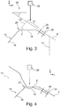
- a slightly modified leading-edge component 29 is shown.
- a flange 30 is arranged at an interior side of the front skin 6, which extends to one side of the first section 16 only.
- the flange 30 thus comprises a larger offset 31 in comparison to the previous exemplary embodiment.
- the deformability is even further improved, as the flange 30 hardly counteracts a folding motion of the first section 16. This can be seen in Fig. 4 , where the front skin 6 reaches a surface of the first section 16 after an impact of the foreign object 26 at a clear distance to the flange 30.
- the flange 30 may provide an avoiding motion in a more spanwise direction.
- the first section 16 and the second section 18 are folded relative to each other and in the shown example, the flange 30 and the first section 16 almost constitute a straight line.
- a rupture of the front skin 6 may be prevented or at least delayed. Due to the design of the rib 14, more impact energy may be absorbed by deforming front skin 6 and folding the rib 14 in comparison with common rib designs.
- Fig. 6 shows an aircraft 32 having wings 34, a horizontal tail plane 36, a vertical tail plane 38 and engines 40. Each of these elements may comprise a leading-edge component 2 or 29 according to the previous illustrations.
- the x-axis is a longitudinal axis parallel to a longitudinal extension of the aircraft 32.
- a vertical axis z is additionally shown.
- the first section 16 and the at least one second section 18 are parallel to the vertical axis z of the aircraft 32.
Landscapes
- Engineering & Computer Science (AREA)
- Aviation & Aerospace Engineering (AREA)
- Mechanical Engineering (AREA)
- Aiming, Guidance, Guns With A Light Source, Armor, Camouflage, And Targets (AREA)
- Tires In General (AREA)
Applications Claiming Priority (1)
| Application Number | Priority Date | Filing Date | Title |
|---|---|---|---|
| DE102019110946 | 2019-04-29 |
Publications (2)
| Publication Number | Publication Date |
|---|---|
| EP3733507A1 true EP3733507A1 (fr) | 2020-11-04 |
| EP3733507B1 EP3733507B1 (fr) | 2024-04-03 |
Family
ID=70470878
Family Applications (1)
| Application Number | Title | Priority Date | Filing Date |
|---|---|---|---|
| EP20171559.6A Active EP3733507B1 (fr) | 2019-04-29 | 2020-04-27 | Composant de bord d'attaque pour un aéronef |
Country Status (3)
| Country | Link |
|---|---|
| US (1) | US11230365B2 (fr) |
| EP (1) | EP3733507B1 (fr) |
| CN (1) | CN111846197B (fr) |
Citations (6)
| Publication number | Priority date | Publication date | Assignee | Title |
|---|---|---|---|---|
| DE69200705T2 (de) * | 1991-08-23 | 1995-03-30 | British Aerospace | Thermoplastische, schmelzverbundene Vorderkante für die aerodynamischen Flächen eines Flugzeuges. |
| EP1371551A1 (fr) * | 2002-06-12 | 2003-12-17 | Honda Giken Kogyo Kabushiki Kaisha | Profil d'aile et sa réalisation dans une aile d'avion |
| DE102005060958A1 (de) * | 2005-12-20 | 2007-06-21 | Airbus Deutschland Gmbh | Schutzvorrichtung |
| US20080237401A1 (en) * | 2004-01-22 | 2008-10-02 | Sonaca S.A. | Mobile Leading Edge Flap for a Main Wing of the Aerofoils of an Aircraft and Main Wing Provided with Such a Flap |
| EP2130762A2 (fr) * | 2008-05-06 | 2009-12-09 | Alenia Aeronautica S.P.A. | Aile et structure de surface portante d'empennage fabriquées en matériau thermoplastique doté d'une configuration à double enveloppe durcie |
| EP3318481A1 (fr) | 2016-11-04 | 2018-05-09 | Airbus Operations, S.L. | Structure de panneau pour aéronef et son procédé de fabrication |
Family Cites Families (10)
| Publication number | Priority date | Publication date | Assignee | Title |
|---|---|---|---|---|
| JP4688661B2 (ja) * | 2005-12-09 | 2011-05-25 | 株式会社イノアックコーポレーション | 車両用衝撃吸収部材 |
| GB201120707D0 (en) * | 2011-12-01 | 2012-01-11 | Airbus Operations Ltd | Leading edge structure |
| CN202953168U (zh) * | 2012-11-09 | 2013-05-29 | 北京航空航天大学 | 一种双梁机翼翼梁新型三角布局结构 |
| US10434731B2 (en) * | 2013-10-31 | 2019-10-08 | Vision Composite Products, Llc | Composite structures having embedded mechanical features |
| CN204250350U (zh) * | 2014-10-11 | 2015-04-08 | 中国航空工业集团公司西安飞机设计研究所 | 一种设置单斜板的飞机前缘抗鸟撞结构 |
| CN204250352U (zh) * | 2014-10-11 | 2015-04-08 | 中国航空工业集团公司西安飞机设计研究所 | 一种飞机机头抗鸟撞翻边结构 |
| JP6782533B2 (ja) * | 2015-08-26 | 2020-11-11 | 三菱航空機株式会社 | 航空機の前縁構造体、航空機の翼及び航空機 |
| CN106697258B (zh) * | 2016-11-28 | 2019-05-10 | 西北工业大学 | 一种能够提高飞机抗鸟撞性能的机翼前缘 |
| CN107082121A (zh) * | 2017-03-30 | 2017-08-22 | 中国航空工业集团公司西安飞机设计研究所 | 一种防鸟撞副油箱 |
| CN108248814A (zh) * | 2018-01-10 | 2018-07-06 | 中国商用飞机有限责任公司 | 飞机抗鸟撞前缘和用于飞机抗鸟撞前缘的支承体 |
-
2020
- 2020-04-20 US US16/852,862 patent/US11230365B2/en active Active
- 2020-04-27 EP EP20171559.6A patent/EP3733507B1/fr active Active
- 2020-04-28 CN CN202010349101.5A patent/CN111846197B/zh active Active
Patent Citations (6)
| Publication number | Priority date | Publication date | Assignee | Title |
|---|---|---|---|---|
| DE69200705T2 (de) * | 1991-08-23 | 1995-03-30 | British Aerospace | Thermoplastische, schmelzverbundene Vorderkante für die aerodynamischen Flächen eines Flugzeuges. |
| EP1371551A1 (fr) * | 2002-06-12 | 2003-12-17 | Honda Giken Kogyo Kabushiki Kaisha | Profil d'aile et sa réalisation dans une aile d'avion |
| US20080237401A1 (en) * | 2004-01-22 | 2008-10-02 | Sonaca S.A. | Mobile Leading Edge Flap for a Main Wing of the Aerofoils of an Aircraft and Main Wing Provided with Such a Flap |
| DE102005060958A1 (de) * | 2005-12-20 | 2007-06-21 | Airbus Deutschland Gmbh | Schutzvorrichtung |
| EP2130762A2 (fr) * | 2008-05-06 | 2009-12-09 | Alenia Aeronautica S.P.A. | Aile et structure de surface portante d'empennage fabriquées en matériau thermoplastique doté d'une configuration à double enveloppe durcie |
| EP3318481A1 (fr) | 2016-11-04 | 2018-05-09 | Airbus Operations, S.L. | Structure de panneau pour aéronef et son procédé de fabrication |
Also Published As
| Publication number | Publication date |
|---|---|
| US11230365B2 (en) | 2022-01-25 |
| CN111846197A (zh) | 2020-10-30 |
| US20210197954A1 (en) | 2021-07-01 |
| EP3733507B1 (fr) | 2024-04-03 |
| CN111846197B (zh) | 2024-06-04 |
Similar Documents
| Publication | Publication Date | Title |
|---|---|---|
| JP6196795B2 (ja) | 性能向上型ウイングレットシステムおよびその方法 | |
| EP0988225B1 (fr) | Extremites d'aile carrossees a bord d'attaque arrondi | |
| EP2397403B1 (fr) | Transition de surface de contrôle du type à morphage | |
| EP3284667B1 (fr) | Agencement d'extrémité d'aile ayant des vortilons fixés à une surface inférieure, aéronef comportant un tel agencement d'extrémité et utilisation des vortilons sur une extrémité | |
| CN103429495B (zh) | 带有后推进系统的飞机 | |
| US9533750B2 (en) | Slat, wing of aircraft, flight control surface of aircraft, and aircraft | |
| US9856013B2 (en) | Deformable wing including a mobile upper surface | |
| CN103373463A (zh) | 飞行器机翼以及具有此种机翼的飞行器 | |
| US12391357B2 (en) | Aircraft design and technology | |
| CN113844648A (zh) | 一种复合式垂直起降固定翼无人机 | |
| US11873095B2 (en) | Leading-edge component for an aircraft | |
| US12172747B2 (en) | Flow control device | |
| US11230365B2 (en) | Leading-edge component for an aircraft | |
| CN112533824B (zh) | 用于改进封闭机翼飞行器概念的方法以及对应的飞行器构造 | |
| CN115783239B (zh) | 一种a字形飞机尾翼前缘的抗鸟撞加强件 | |
| EP3976466B1 (fr) | Composante de bord d'attaque pour aéronef | |
| US12365441B2 (en) | Spoiler | |
| US20250121928A1 (en) | Aircraft assembly |
Legal Events
| Date | Code | Title | Description |
|---|---|---|---|
| PUAI | Public reference made under article 153(3) epc to a published international application that has entered the european phase |
Free format text: ORIGINAL CODE: 0009012 |
|
| STAA | Information on the status of an ep patent application or granted ep patent |
Free format text: STATUS: THE APPLICATION HAS BEEN PUBLISHED |
|
| AK | Designated contracting states |
Kind code of ref document: A1 Designated state(s): AL AT BE BG CH CY CZ DE DK EE ES FI FR GB GR HR HU IE IS IT LI LT LU LV MC MK MT NL NO PL PT RO RS SE SI SK SM TR |
|
| AX | Request for extension of the european patent |
Extension state: BA ME |
|
| STAA | Information on the status of an ep patent application or granted ep patent |
Free format text: STATUS: REQUEST FOR EXAMINATION WAS MADE |
|
| 17P | Request for examination filed |
Effective date: 20210504 |
|
| RBV | Designated contracting states (corrected) |
Designated state(s): AL AT BE BG CH CY CZ DE DK EE ES FI FR GB GR HR HU IE IS IT LI LT LU LV MC MK MT NL NO PL PT RO RS SE SI SK SM TR |
|
| STAA | Information on the status of an ep patent application or granted ep patent |
Free format text: STATUS: EXAMINATION IS IN PROGRESS |
|
| 17Q | First examination report despatched |
Effective date: 20210923 |
|
| GRAP | Despatch of communication of intention to grant a patent |
Free format text: ORIGINAL CODE: EPIDOSNIGR1 |
|
| STAA | Information on the status of an ep patent application or granted ep patent |
Free format text: STATUS: GRANT OF PATENT IS INTENDED |
|
| INTG | Intention to grant announced |
Effective date: 20240124 |
|
| GRAS | Grant fee paid |
Free format text: ORIGINAL CODE: EPIDOSNIGR3 |
|
| GRAA | (expected) grant |
Free format text: ORIGINAL CODE: 0009210 |
|
| STAA | Information on the status of an ep patent application or granted ep patent |
Free format text: STATUS: THE PATENT HAS BEEN GRANTED |
|
| AK | Designated contracting states |
Kind code of ref document: B1 Designated state(s): AL AT BE BG CH CY CZ DE DK EE ES FI FR GB GR HR HU IE IS IT LI LT LU LV MC MK MT NL NO PL PT RO RS SE SI SK SM TR |
|
| REG | Reference to a national code |
Ref country code: CH Ref legal event code: EP |
|
| REG | Reference to a national code |
Ref country code: IE Ref legal event code: FG4D |
|
| REG | Reference to a national code |
Ref country code: DE Ref legal event code: R096 Ref document number: 602020028197 Country of ref document: DE |
|
| REG | Reference to a national code |
Ref country code: LT Ref legal event code: MG9D |
|
| REG | Reference to a national code |
Ref country code: NL Ref legal event code: MP Effective date: 20240403 |
|
| REG | Reference to a national code |
Ref country code: AT Ref legal event code: MK05 Ref document number: 1672024 Country of ref document: AT Kind code of ref document: T Effective date: 20240403 |
|
| PG25 | Lapsed in a contracting state [announced via postgrant information from national office to epo] |
Ref country code: NL Free format text: LAPSE BECAUSE OF FAILURE TO SUBMIT A TRANSLATION OF THE DESCRIPTION OR TO PAY THE FEE WITHIN THE PRESCRIBED TIME-LIMIT Effective date: 20240403 |
|
| PG25 | Lapsed in a contracting state [announced via postgrant information from national office to epo] |
Ref country code: NL Free format text: LAPSE BECAUSE OF FAILURE TO SUBMIT A TRANSLATION OF THE DESCRIPTION OR TO PAY THE FEE WITHIN THE PRESCRIBED TIME-LIMIT Effective date: 20240403 |
|
| PG25 | Lapsed in a contracting state [announced via postgrant information from national office to epo] |
Ref country code: IS Free format text: LAPSE BECAUSE OF FAILURE TO SUBMIT A TRANSLATION OF THE DESCRIPTION OR TO PAY THE FEE WITHIN THE PRESCRIBED TIME-LIMIT Effective date: 20240803 |
|
| PG25 | Lapsed in a contracting state [announced via postgrant information from national office to epo] |
Ref country code: BG Free format text: LAPSE BECAUSE OF FAILURE TO SUBMIT A TRANSLATION OF THE DESCRIPTION OR TO PAY THE FEE WITHIN THE PRESCRIBED TIME-LIMIT Effective date: 20240403 |
|
| PG25 | Lapsed in a contracting state [announced via postgrant information from national office to epo] |
Ref country code: FI Free format text: LAPSE BECAUSE OF FAILURE TO SUBMIT A TRANSLATION OF THE DESCRIPTION OR TO PAY THE FEE WITHIN THE PRESCRIBED TIME-LIMIT Effective date: 20240403 Ref country code: HR Free format text: LAPSE BECAUSE OF FAILURE TO SUBMIT A TRANSLATION OF THE DESCRIPTION OR TO PAY THE FEE WITHIN THE PRESCRIBED TIME-LIMIT Effective date: 20240403 |
|
| PG25 | Lapsed in a contracting state [announced via postgrant information from national office to epo] |
Ref country code: GR Free format text: LAPSE BECAUSE OF FAILURE TO SUBMIT A TRANSLATION OF THE DESCRIPTION OR TO PAY THE FEE WITHIN THE PRESCRIBED TIME-LIMIT Effective date: 20240704 |
|
| PG25 | Lapsed in a contracting state [announced via postgrant information from national office to epo] |
Ref country code: PT Free format text: LAPSE BECAUSE OF FAILURE TO SUBMIT A TRANSLATION OF THE DESCRIPTION OR TO PAY THE FEE WITHIN THE PRESCRIBED TIME-LIMIT Effective date: 20240805 |
|
| PG25 | Lapsed in a contracting state [announced via postgrant information from national office to epo] |
Ref country code: ES Free format text: LAPSE BECAUSE OF FAILURE TO SUBMIT A TRANSLATION OF THE DESCRIPTION OR TO PAY THE FEE WITHIN THE PRESCRIBED TIME-LIMIT Effective date: 20240403 |
|
| PG25 | Lapsed in a contracting state [announced via postgrant information from national office to epo] |
Ref country code: CZ Free format text: LAPSE BECAUSE OF FAILURE TO SUBMIT A TRANSLATION OF THE DESCRIPTION OR TO PAY THE FEE WITHIN THE PRESCRIBED TIME-LIMIT Effective date: 20240403 |
|
| PG25 | Lapsed in a contracting state [announced via postgrant information from national office to epo] |
Ref country code: AT Free format text: LAPSE BECAUSE OF FAILURE TO SUBMIT A TRANSLATION OF THE DESCRIPTION OR TO PAY THE FEE WITHIN THE PRESCRIBED TIME-LIMIT Effective date: 20240403 |
|
| PG25 | Lapsed in a contracting state [announced via postgrant information from national office to epo] |
Ref country code: PL Free format text: LAPSE BECAUSE OF FAILURE TO SUBMIT A TRANSLATION OF THE DESCRIPTION OR TO PAY THE FEE WITHIN THE PRESCRIBED TIME-LIMIT Effective date: 20240403 |
|
| PG25 | Lapsed in a contracting state [announced via postgrant information from national office to epo] |
Ref country code: LV Free format text: LAPSE BECAUSE OF FAILURE TO SUBMIT A TRANSLATION OF THE DESCRIPTION OR TO PAY THE FEE WITHIN THE PRESCRIBED TIME-LIMIT Effective date: 20240403 |
|
| PG25 | Lapsed in a contracting state [announced via postgrant information from national office to epo] |
Ref country code: PT Free format text: LAPSE BECAUSE OF FAILURE TO SUBMIT A TRANSLATION OF THE DESCRIPTION OR TO PAY THE FEE WITHIN THE PRESCRIBED TIME-LIMIT Effective date: 20240805 Ref country code: PL Free format text: LAPSE BECAUSE OF FAILURE TO SUBMIT A TRANSLATION OF THE DESCRIPTION OR TO PAY THE FEE WITHIN THE PRESCRIBED TIME-LIMIT Effective date: 20240403 Ref country code: NO Free format text: LAPSE BECAUSE OF FAILURE TO SUBMIT A TRANSLATION OF THE DESCRIPTION OR TO PAY THE FEE WITHIN THE PRESCRIBED TIME-LIMIT Effective date: 20240703 Ref country code: LV Free format text: LAPSE BECAUSE OF FAILURE TO SUBMIT A TRANSLATION OF THE DESCRIPTION OR TO PAY THE FEE WITHIN THE PRESCRIBED TIME-LIMIT Effective date: 20240403 Ref country code: IS Free format text: LAPSE BECAUSE OF FAILURE TO SUBMIT A TRANSLATION OF THE DESCRIPTION OR TO PAY THE FEE WITHIN THE PRESCRIBED TIME-LIMIT Effective date: 20240803 Ref country code: HR Free format text: LAPSE BECAUSE OF FAILURE TO SUBMIT A TRANSLATION OF THE DESCRIPTION OR TO PAY THE FEE WITHIN THE PRESCRIBED TIME-LIMIT Effective date: 20240403 Ref country code: GR Free format text: LAPSE BECAUSE OF FAILURE TO SUBMIT A TRANSLATION OF THE DESCRIPTION OR TO PAY THE FEE WITHIN THE PRESCRIBED TIME-LIMIT Effective date: 20240704 Ref country code: FI Free format text: LAPSE BECAUSE OF FAILURE TO SUBMIT A TRANSLATION OF THE DESCRIPTION OR TO PAY THE FEE WITHIN THE PRESCRIBED TIME-LIMIT Effective date: 20240403 Ref country code: ES Free format text: LAPSE BECAUSE OF FAILURE TO SUBMIT A TRANSLATION OF THE DESCRIPTION OR TO PAY THE FEE WITHIN THE PRESCRIBED TIME-LIMIT Effective date: 20240403 Ref country code: CZ Free format text: LAPSE BECAUSE OF FAILURE TO SUBMIT A TRANSLATION OF THE DESCRIPTION OR TO PAY THE FEE WITHIN THE PRESCRIBED TIME-LIMIT Effective date: 20240403 Ref country code: BG Free format text: LAPSE BECAUSE OF FAILURE TO SUBMIT A TRANSLATION OF THE DESCRIPTION OR TO PAY THE FEE WITHIN THE PRESCRIBED TIME-LIMIT Effective date: 20240403 Ref country code: AT Free format text: LAPSE BECAUSE OF FAILURE TO SUBMIT A TRANSLATION OF THE DESCRIPTION OR TO PAY THE FEE WITHIN THE PRESCRIBED TIME-LIMIT Effective date: 20240403 Ref country code: RS Free format text: LAPSE BECAUSE OF FAILURE TO SUBMIT A TRANSLATION OF THE DESCRIPTION OR TO PAY THE FEE WITHIN THE PRESCRIBED TIME-LIMIT Effective date: 20240703 |
|
| REG | Reference to a national code |
Ref country code: CH Ref legal event code: PL |
|
| PG25 | Lapsed in a contracting state [announced via postgrant information from national office to epo] |
Ref country code: LU Free format text: LAPSE BECAUSE OF NON-PAYMENT OF DUE FEES Effective date: 20240427 |
|
| REG | Reference to a national code |
Ref country code: BE Ref legal event code: MM Effective date: 20240430 |
|
| PG25 | Lapsed in a contracting state [announced via postgrant information from national office to epo] |
Ref country code: LU Free format text: LAPSE BECAUSE OF NON-PAYMENT OF DUE FEES Effective date: 20240427 |
|
| REG | Reference to a national code |
Ref country code: DE Ref legal event code: R097 Ref document number: 602020028197 Country of ref document: DE |
|
| PG25 | Lapsed in a contracting state [announced via postgrant information from national office to epo] |
Ref country code: DK Free format text: LAPSE BECAUSE OF FAILURE TO SUBMIT A TRANSLATION OF THE DESCRIPTION OR TO PAY THE FEE WITHIN THE PRESCRIBED TIME-LIMIT Effective date: 20240403 |
|
| PG25 | Lapsed in a contracting state [announced via postgrant information from national office to epo] |
Ref country code: BE Free format text: LAPSE BECAUSE OF NON-PAYMENT OF DUE FEES Effective date: 20240430 |
|
| PG25 | Lapsed in a contracting state [announced via postgrant information from national office to epo] |
Ref country code: EE Free format text: LAPSE BECAUSE OF FAILURE TO SUBMIT A TRANSLATION OF THE DESCRIPTION OR TO PAY THE FEE WITHIN THE PRESCRIBED TIME-LIMIT Effective date: 20240403 |
|
| PG25 | Lapsed in a contracting state [announced via postgrant information from national office to epo] |
Ref country code: RO Free format text: LAPSE BECAUSE OF FAILURE TO SUBMIT A TRANSLATION OF THE DESCRIPTION OR TO PAY THE FEE WITHIN THE PRESCRIBED TIME-LIMIT Effective date: 20240403 Ref country code: SK Free format text: LAPSE BECAUSE OF FAILURE TO SUBMIT A TRANSLATION OF THE DESCRIPTION OR TO PAY THE FEE WITHIN THE PRESCRIBED TIME-LIMIT Effective date: 20240403 |
|
| PG25 | Lapsed in a contracting state [announced via postgrant information from national office to epo] |
Ref country code: SM Free format text: LAPSE BECAUSE OF FAILURE TO SUBMIT A TRANSLATION OF THE DESCRIPTION OR TO PAY THE FEE WITHIN THE PRESCRIBED TIME-LIMIT Effective date: 20240403 |
|
| PG25 | Lapsed in a contracting state [announced via postgrant information from national office to epo] |
Ref country code: SM Free format text: LAPSE BECAUSE OF FAILURE TO SUBMIT A TRANSLATION OF THE DESCRIPTION OR TO PAY THE FEE WITHIN THE PRESCRIBED TIME-LIMIT Effective date: 20240403 Ref country code: SK Free format text: LAPSE BECAUSE OF FAILURE TO SUBMIT A TRANSLATION OF THE DESCRIPTION OR TO PAY THE FEE WITHIN THE PRESCRIBED TIME-LIMIT Effective date: 20240403 Ref country code: RO Free format text: LAPSE BECAUSE OF FAILURE TO SUBMIT A TRANSLATION OF THE DESCRIPTION OR TO PAY THE FEE WITHIN THE PRESCRIBED TIME-LIMIT Effective date: 20240403 Ref country code: EE Free format text: LAPSE BECAUSE OF FAILURE TO SUBMIT A TRANSLATION OF THE DESCRIPTION OR TO PAY THE FEE WITHIN THE PRESCRIBED TIME-LIMIT Effective date: 20240403 Ref country code: DK Free format text: LAPSE BECAUSE OF FAILURE TO SUBMIT A TRANSLATION OF THE DESCRIPTION OR TO PAY THE FEE WITHIN THE PRESCRIBED TIME-LIMIT Effective date: 20240403 Ref country code: BE Free format text: LAPSE BECAUSE OF NON-PAYMENT OF DUE FEES Effective date: 20240430 Ref country code: MC Free format text: LAPSE BECAUSE OF FAILURE TO SUBMIT A TRANSLATION OF THE DESCRIPTION OR TO PAY THE FEE WITHIN THE PRESCRIBED TIME-LIMIT Effective date: 20240403 Ref country code: CH Free format text: LAPSE BECAUSE OF NON-PAYMENT OF DUE FEES Effective date: 20240430 |
|
| PLBE | No opposition filed within time limit |
Free format text: ORIGINAL CODE: 0009261 |
|
| STAA | Information on the status of an ep patent application or granted ep patent |
Free format text: STATUS: NO OPPOSITION FILED WITHIN TIME LIMIT |
|
| 26N | No opposition filed |
Effective date: 20250106 |
|
| PG25 | Lapsed in a contracting state [announced via postgrant information from national office to epo] |
Ref country code: IE Free format text: LAPSE BECAUSE OF NON-PAYMENT OF DUE FEES Effective date: 20240427 |
|
| PG25 | Lapsed in a contracting state [announced via postgrant information from national office to epo] |
Ref country code: SI Free format text: LAPSE BECAUSE OF FAILURE TO SUBMIT A TRANSLATION OF THE DESCRIPTION OR TO PAY THE FEE WITHIN THE PRESCRIBED TIME-LIMIT Effective date: 20240403 |
|
| PGFP | Annual fee paid to national office [announced via postgrant information from national office to epo] |
Ref country code: DE Payment date: 20250422 Year of fee payment: 6 |
|
| PGFP | Annual fee paid to national office [announced via postgrant information from national office to epo] |
Ref country code: GB Payment date: 20250423 Year of fee payment: 6 |
|
| PGFP | Annual fee paid to national office [announced via postgrant information from national office to epo] |
Ref country code: FR Payment date: 20250425 Year of fee payment: 6 |
|
| PG25 | Lapsed in a contracting state [announced via postgrant information from national office to epo] |
Ref country code: CY Free format text: LAPSE BECAUSE OF FAILURE TO SUBMIT A TRANSLATION OF THE DESCRIPTION OR TO PAY THE FEE WITHIN THE PRESCRIBED TIME-LIMIT; INVALID AB INITIO Effective date: 20200427 |
|
| PG25 | Lapsed in a contracting state [announced via postgrant information from national office to epo] |
Ref country code: HU Free format text: LAPSE BECAUSE OF FAILURE TO SUBMIT A TRANSLATION OF THE DESCRIPTION OR TO PAY THE FEE WITHIN THE PRESCRIBED TIME-LIMIT; INVALID AB INITIO Effective date: 20200427 |
|
| PG25 | Lapsed in a contracting state [announced via postgrant information from national office to epo] |
Ref country code: SE Free format text: LAPSE BECAUSE OF FAILURE TO SUBMIT A TRANSLATION OF THE DESCRIPTION OR TO PAY THE FEE WITHIN THE PRESCRIBED TIME-LIMIT Effective date: 20240403 |
|
| PG25 | Lapsed in a contracting state [announced via postgrant information from national office to epo] |
Ref country code: IT Free format text: LAPSE BECAUSE OF FAILURE TO SUBMIT A TRANSLATION OF THE DESCRIPTION OR TO PAY THE FEE WITHIN THE PRESCRIBED TIME-LIMIT Effective date: 20240403 |