EP3733581B1 - Algorithmus zur erkennung einer aufzugsbewegungsrichtung - Google Patents
Algorithmus zur erkennung einer aufzugsbewegungsrichtung Download PDFInfo
- Publication number
- EP3733581B1 EP3733581B1 EP20172607.2A EP20172607A EP3733581B1 EP 3733581 B1 EP3733581 B1 EP 3733581B1 EP 20172607 A EP20172607 A EP 20172607A EP 3733581 B1 EP3733581 B1 EP 3733581B1
- Authority
- EP
- European Patent Office
- Prior art keywords
- conveyance
- time
- elevator
- elevator car
- height
- Prior art date
- Legal status (The legal status is an assumption and is not a legal conclusion. Google has not performed a legal analysis and makes no representation as to the accuracy of the status listed.)
- Active
Links
Images


Classifications
-
- B—PERFORMING OPERATIONS; TRANSPORTING
- B66—HOISTING; LIFTING; HAULING
- B66B—ELEVATORS; ESCALATORS OR MOVING WALKWAYS
- B66B1/00—Control systems of elevators in general
- B66B1/34—Details, e.g. call counting devices, data transmission from car to control system, devices giving information to the control system
- B66B1/3492—Position or motion detectors or driving means for the detector
-
- B—PERFORMING OPERATIONS; TRANSPORTING
- B66—HOISTING; LIFTING; HAULING
- B66B—ELEVATORS; ESCALATORS OR MOVING WALKWAYS
- B66B5/00—Applications of checking, fault-correcting, or safety devices in elevators
- B66B5/0006—Monitoring devices or performance analysers
- B66B5/0018—Devices monitoring the operating condition of the elevator system
Definitions
- the embodiments herein relate to the field of conveyance systems, and specifically to a method and apparatus for monitoring a direction of motion of a conveyance apparatus within a conveyance system.
- a precise position and/or direction of motion of a conveyance apparatus within a conveyance systems may be difficult and/or costly to determine.
- EP3450990 describes an electronic speed detection system comprising an accelerometer coupled to a moving object and a hybrid altimeter.
- CN108861917 describes a method for checking elevator operation through a WeChat platform.
- WO2011/032660 describes a consumer control device and a method for actuating at least one consumer of an elevator.
- a method of monitoring a direction of motion of a conveyance apparatus within a conveyance system is provided according to claim 1.
- Some embodiments may include that the conveyance system is an elevator system and the conveyance apparatus is an elevator car.
- Some embodiments may include that the conveyance system is an elevator system and the conveyance apparatus is an elevator car.
- inventions of the present disclosure include determining a direction of motion of a conveyance apparatus within a conveyance system in response to a rate of change in atmospheric pressure within the conveyance system proximate the conveyance apparatus.
- FIG. 1 is a perspective view of an elevator system 101 including an elevator car 103, a counterweight 105, a tension member 107, a guide rail 109, a machine 111, a position reference system 113, and a controller 115.
- the elevator car 103 and counterweight 105 are connected to each other by the tension member 107.
- the tension member 107 may include or be configured as, for example, ropes, steel cables, and/or coated-steel belts.
- the counterweight 105 is configured to balance a load of the elevator car 103 and is configured to facilitate movement of the elevator car 103 concurrently and in an opposite direction with respect to the counterweight 105 within an elevator shaft 117 and along the guide rail 109.
- the tension member 107 engages the machine 111, which is part of an overhead structure of the elevator system 101.
- the machine 111 is configured to control movement between the elevator car 103 and the counterweight 105.
- the position reference system 113 may be mounted on a fixed part at the top of the elevator shaft 117, such as on a support or guide rail, and may be configured to provide position signals related to a position of the elevator car 103 within the elevator shaft 117. In other embodiments, the position reference system 113 may be directly mounted to a moving component of the machine 111, or may be located in other positions and/or configurations as known in the art.
- the position reference system 113 can be any device or mechanism for monitoring a position of an elevator car and/or counter weight, as known in the art.
- the position reference system 113 can be an encoder, sensor, or other system and can include velocity sensing, absolute position sensing, etc., as will be appreciated by those of skill in the art.
- the controller 115 is located, as shown, in a controller room 121 of the elevator shaft 117 and is configured to control the operation of the elevator system 101, and particularly the elevator car 103.
- the controller 115 may provide drive signals to the machine 111 to control the acceleration, deceleration, leveling, stopping, etc. of the elevator car 103.
- the controller 115 may also be configured to receive position signals from the position reference system 113 or any other desired position reference device.
- the elevator car 103 may stop at one or more landings 125 as controlled by the controller 115.
- the controller 115 can be located and/or configured in other locations or positions within the elevator system 101. In one embodiment, the controller may be located remotely or in the cloud.
- the pressure data 314 may include atmospheric air pressure within the elevator shaft 117. It should be appreciated that, although particular systems are separately defined in the schematic block diagrams, each or any of the systems may be otherwise combined or separated via hardware and/or software.
- the sensing apparatus 210 may be a single sensor or may be multiple separate sensors that are interconnected.
- FIG. 4 illustrates a block diagram of the sensing apparatus 210 of the sensing system of FIGs. 2 and 3 . It should be appreciated that, although particular systems are separately defined in the schematic block diagram of FIG. 4 , each or any of the systems may be otherwise combined or separated via hardware and/or software. As shown in FIG. 4 , the sensing apparatus 210 may include a controller 212, a plurality of sensors 217 in communication with the controller 212, a communication module 220 in communication with the controller 212, and a power source 222 electrically connected to the controller 212.
- the sensing apparatus 210 includes a communication module 220 configured to allow the controller 212 of the sensing apparatus 210 to communicate with the remote device 280 and/or controller 115 through at least one of short-range wireless protocols 203 and long-range wireless protocols 204.
- the communication module 220 may be configured to communicate with the remote device 280 using short-range wireless protocols 203, such as, for example, Bluetooth, Wi-Fi, HaLow (801.11ah), Wireless M-Bus, zWave, ZigBee, or other short-range wireless protocol known to one of skill in the art.
- the short-range wireless protocol 203 is sub GHz Wireless M-Bus.
- the long-range wireless protocol is SigFox.
- the long-range wireless protocol is LTE NB-IoT or CAT M1 with 2G fallback.
- the location determination module 330 may then determine the location of the elevator car 103 within the elevator shaft 117 in response to a starting location and a distance traveled away from that starting location.
- the starting location may be based upon tracking the past operation and/or movement of the elevator car 103.
- the baseline pressure may be detected whenever the elevator car 103 is stationary, or at certain intervals when the elevator car 103 is stationary and/or at a known location.
- the acceleration of the elevator car 103 may also need to be detected to know when the elevator car 103 is stationary and then when the elevator car 103 is stationary the sensing apparatus 210 may need to be offset to compensate the sensor drift and environment drift.
- FIG. 5 shows a flow chart of a method 500 of monitoring a direction of motion of a conveyance apparatus within a conveyance system, in accordance with an embodiment of the disclosure.
- the conveyance system is an elevator system 101 and the conveyance apparatus is an elevator car 103.
- the method 500 may be performed by at least one of the sensing apparatus 210, the controller 115, and the remote device 280.
- a height change of the conveyance apparatus within the conveyance system is detected.
- the height change may be determined by detecting a change in atmospheric air pressure within the conveyance system.
- a first atmospheric air pressure is detected within the conveyance system proximate the conveyance apparatus at a first time and a second atmospheric air pressure is detected within the conveyance system proximate the conveyance apparatus at a second time.
- the atmospheric air pressure (e.g., the first atmospheric air pressure and the second atmospheric air pressure) may be detected by the pressure sensor 228 may be associated with a location (e.g., height) within the elevator shaft 117 through either a look up table or a calculation of altitude using the barometric pressure change in two non-limiting embodiments.
- the pressure sensor 228 may need to periodically detect a baseline pressure to account for changes in atmospheric pressure due to local weather conditions or sensor drift. For example, this baseline pressure may need to be detected daily, hourly, or weekly in non-limiting embodiments.
- a change in atmospheric air pressure proximate the conveyance apparatus is determined in response to the first atmospheric air pressure and the second atmospheric air pressure within the conveyance system, which may mean a change in height.
- a height change height change of a conveyance apparatus within the conveyance system between the first time and the second time may be determined in response to the change in atmospheric air pressure within the conveyance system proximate the conveyance apparatus.
- a direction of motion (e.g., upward or downward) of the conveyance apparatus within the conveyance system may be determined in response to the change in height.
- the direction of motion of the conveyance apparatus is determined by blocks 506-516. For example, changes in height over a period of time may indicate motion.
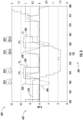
- the method may use an up(t 1 ) function to indicate that the conveyance apparatus is moving up at a first time t 1 and a down(t 2 ) function to indicate that the conveyance apparatus is moving down at a second time t 2 .
- first time t 1 may be equivalent to the second time t 2 (i.e., the same time) and the first time t 1 and the second time t 2 are illustrated as different time in FIG. 6 for ease of explanation so that they may appear separately in FIG. 6 .
- a change in height 602 of the conveyance apparatus over a period of time 604 is detected by a sensing apparatus 210 detecting a change in atmospheric pressure, as shown by line 610 in chart 600.
- Vertical acceleration of the conveyance apparatus is also plotted on chart 600, as shown by line 606, for exemplary purposes.
- the vertical acceleration of the conveyance apparatus may not always by correlated with vertical movement of the conveyance apparatus, as shown by line 610, which may be due to various vibrations experience by the conveyance apparatus while stopped (e.g., doors 104 opening and closing, or passengers moving in and out, etc.).
- the h(t 1 ) is the height of the conveyance apparatus at the first time t 1
- the h(t 1 - ⁇ T 1 ) is the height of the conveyance apparatus at the first selected time period ⁇ T 1 prior to the first time t 1
- the first selected time period ⁇ T 1 may be five seconds and the first selected height change ⁇ h 1 may be 1.5 meters (4.92 feet).
- the up(t 1 ) function is true as shown by line 620 of FIG. 6 and the method 500 moves onto block 510 where it is determined that the height change was upward and then the method 500 may move to block 522.
- the up(t 1 ) function is not true (i.e., FALSE) and the method 500 moves onto block 512.
- an upward corrective value UCV1 is subtracted from the first selected time period ⁇ T 1 and the first time t 1 to shift the first selected time period ⁇ TP 1 and the first time t 1 into the past by the upward corrective value UCV1 because there may be a delay in detecting the upward movement of the conveyance apparatus and actual upward movement.
- the upward corrective value UCV1 shifts the true up(t 1 ) function as shown by line 620 to line 640 of FIG. 6 .
- the upward corrective value UCV1 may be determined from close historical examination (e.g., experimentation) of the time delay in detecting the upward movement of the conveyance apparatus. In one embodiment, the upward corrective value UCV1 may be equal to three seconds.
- the upward corrective value UCV1 is applied to the first time t 1 and the first time period ⁇ T 1 prior to the first time t 1 and it may be determined that the conveyance apparatus was moving in the upward direction in a time period between the first time t 1 minus the upward corrective value UCV1 and the first selected time period ⁇ T 1 prior to the first time t 1 minus the upward corrective value UCV1.
- a downward corrective value DCV1 is subtracted from the first selected time period ⁇ T 1 and the second time t 2 to shift the first selected time period ⁇ TP 1 and the second time t 2 into the past by the downward corrective value DCV1 because there may be a delay in detecting the downward movement of the conveyance apparatus and actual downward movement.
- the downward corrective value DCV1 shifts the true down(t 2 ) function as shown by line 630 to line 650 of FIG. 6 .
- the downward corrective value DCV1 may be determined from close historical examination (e.g., experimentation) of the time delay in detecting the downward movement of the conveyance apparatus. In one embodiment, the downward corrective value DCV1 may be equal to three seconds.
Landscapes
- Engineering & Computer Science (AREA)
- Automation & Control Theory (AREA)
- Computer Networks & Wireless Communication (AREA)
- Indicating And Signalling Devices For Elevators (AREA)
- Maintenance And Inspection Apparatuses For Elevators (AREA)
Claims (4)
- Verfahren zum Überwachen einer Bewegungsrichtung einer Fördervorrichtung (103) innerhalb eines Fördersystems (101), wobei das Verfahren Folgendes umfasst:Erkennen einer ersten Höhe zu einem ersten Zeitpunkt;Erkennen einer zweiten Höhe zu einem ersten ausgewählten Zeitraum vor dem ersten Zeitpunkt;Erkennen einer Höhenänderung einer Fördervorrichtung (103) innerhalb des Fördersystems (101) als Reaktion auf die erste Höhe und die zweite Höhe;Bestimmen, ob die Höhenänderung größer als eine erste ausgewählte Höhenänderung ist; undBestimmen, dass sich die Fördervorrichtung (103) in eine Aufwärtsrichtung bewegt, wenn die Höhenänderung größer als die erste ausgewählte Höhenänderung ist;dadurch gekennzeichnet, dass das Verfahren ferner Folgendes umfasst:Anwenden eines Aufwärtskorrekturwerts auf den ersten Zeitpunkt und den ersten Zeitraum vor dem ersten Zeitpunkt; undBestimmen, dass sich die Fördervorrichtung (103) in einem Zeitraum zwischen dem ersten Zeitpunkt abzüglich des Aufwärtskorrekturwerts und dem ersten ausgewählten Zeitraum vor dem ersten Zeitpunkt abzüglich des Aufwärtskorrekturwerts in Aufwärtsrichtung bewegte.
- Verfahren nach Anspruch 1, wobei das Fördersystem (101) ein Aufzugssystem und die Fördervorrichtung (103) eine Aufzugskabine ist.
- Verfahren zum Überwachen einer Bewegungsrichtung einer Fördervorrichtung (103) innerhalb eines Fördersystems (101), wobei das Verfahren Folgendes umfasst:Erkennen einer ersten Höhe zu einem ersten Zeitpunkt;Erkennen einer zweiten Höhe zu einem ersten ausgewählten Zeitraum vor dem ersten Zeitpunkt;Erkennen einer Höhenänderung einer Fördervorrichtung (103) innerhalb des Fördersystems (101) als Reaktion auf die erste Höhe und die zweite Höhe;Bestimmen, ob die Höhenänderung kleiner als eine erste ausgewählte Höhenänderung ist; undBestimmen, dass sich die Fördervorrichtung (103) in eine Abwärtsrichtung bewegt, wenn die Höhenänderung kleiner als die erste ausgewählte Höhenänderung ist;dadurch gekennzeichnet, dass das Verfahren ferner Folgendes umfasst:Anwenden eines Abwärtskorrekturwerts auf den ersten Zeitpunkt und den ersten Zeitraum vor dem ersten Zeitpunkt; undBestimmen, dass sich die Fördervorrichtung (103) in einem Zeitraum zwischen dem ersten Zeitpunkt abzüglich des Abwärtskorrekturwerts und dem ersten ausgewählten Zeitraum vor dem ersten Zeitpunkt abzüglich des Abwärtskorrekturwerts in Abwärtsrichtung bewegte.
- Verfahren nach Anspruch 3, wobei das Fördersystem (101) ein Aufzugssystem und die Fördervorrichtung (103) eine Aufzugskabine ist.
Applications Claiming Priority (1)
| Application Number | Priority Date | Filing Date | Title |
|---|---|---|---|
| US16/400,448 US11987472B2 (en) | 2019-05-01 | 2019-05-01 | Air pressure sensor algorithm to detect elevator direction of motion |
Publications (2)
| Publication Number | Publication Date |
|---|---|
| EP3733581A1 EP3733581A1 (de) | 2020-11-04 |
| EP3733581B1 true EP3733581B1 (de) | 2024-12-18 |
Family
ID=70482498
Family Applications (1)
| Application Number | Title | Priority Date | Filing Date |
|---|---|---|---|
| EP20172607.2A Active EP3733581B1 (de) | 2019-05-01 | 2020-05-01 | Algorithmus zur erkennung einer aufzugsbewegungsrichtung |
Country Status (4)
| Country | Link |
|---|---|
| US (1) | US11987472B2 (de) |
| EP (1) | EP3733581B1 (de) |
| CN (1) | CN111874763A (de) |
| ES (1) | ES3015264T3 (de) |
Families Citing this family (2)
| Publication number | Priority date | Publication date | Assignee | Title |
|---|---|---|---|---|
| CN113104690B (zh) * | 2021-03-16 | 2022-08-30 | 嘉兴市特种设备检验检测院 | 用于检测高速电梯轿厢内气压的检测装置和检测系统 |
| CN114212640B (zh) * | 2022-02-22 | 2022-05-13 | 深圳市海清视讯科技有限公司 | 楼层定位方法及设备 |
Family Cites Families (19)
| Publication number | Priority date | Publication date | Assignee | Title |
|---|---|---|---|---|
| JPS56117969A (en) | 1980-02-22 | 1981-09-16 | Hitachi Ltd | Device and method of controlling elevator |
| US4939679A (en) * | 1988-08-09 | 1990-07-03 | Otis Elevator Company | Recalibrating an elevator load measuring system |
| DE102006033605B8 (de) | 2006-07-18 | 2008-07-10 | Fraba Ag | Vorrichtung und Verfahren zur Bestimmung von Vertikalpositionen |
| DE102009041330A1 (de) | 2009-09-15 | 2011-04-07 | Henning Gmbh | Verbrauchersteuereinrichtung und Verfahren zur Betätigung wenigstens eines Verbrauchers eines Aufzugs |
| JP5518915B2 (ja) * | 2012-02-20 | 2014-06-11 | 東芝エレベータ株式会社 | エレベータのかご移動制御装置及びかご移動制御方法 |
| JP5986125B2 (ja) | 2014-02-28 | 2016-09-06 | ファナック株式会社 | 無線センサを有する機械システム |
| US20170225921A1 (en) * | 2014-07-28 | 2017-08-10 | Otis Elevator Company | Elevator car location sensing system |
| CN104909232A (zh) | 2015-06-29 | 2015-09-16 | 周志鸿 | 一种电梯运行高度检测装置和系统 |
| CN105712142B (zh) | 2016-03-22 | 2018-01-12 | 上海点络信息技术有限公司 | 一种电梯运行状态的检测系统及检测方法 |
| US10578639B2 (en) | 2017-08-28 | 2020-03-03 | Otis Elevator Company | Hybrid altimeter for measuring vertical velocity |
| CN108408516A (zh) | 2018-03-08 | 2018-08-17 | 宁夏电通物联网科技股份有限公司 | 基于激光测距技术的电梯楼层检测装置及电梯系统及方法 |
| CN108861917A (zh) | 2018-06-22 | 2018-11-23 | 广西烽火信息技术有限公司 | 一种通过微信平台查看电梯运行的方法 |
| CN108726299B (zh) | 2018-06-22 | 2020-09-04 | 广西数百益物联科技有限公司 | 一种基于气压变化监控电梯运行位置的方法 |
| CN108946367B (zh) | 2018-09-12 | 2021-05-25 | 广州瓦良格机器人科技有限公司 | 基于相对气压及高度误差校正的电梯运行检测方法及装置 |
| US10822199B2 (en) * | 2019-03-28 | 2020-11-03 | Otis Elevator Company | Sensor fusion of acceleration sensor and air pressure sensor information to estimate elevator floor level and position |
| US12084310B2 (en) * | 2019-07-31 | 2024-09-10 | Otis Elevator Company | Pressure sensor algorithm to detect elevator status information |
| US12202705B2 (en) * | 2019-09-20 | 2025-01-21 | Otis Elevator Company | Estimation and presentation of area of interest for condition based monitoring on doors: door health heat map |
| US12319539B2 (en) * | 2019-09-20 | 2025-06-03 | Otis Elevator Company | Air pressure floor table detection: statistical analysis of location |
| US12139370B2 (en) * | 2019-09-27 | 2024-11-12 | Otis Elevator Company | Air pressure and acceleration sensor floor correction by elevator status information |
-
2019
- 2019-05-01 US US16/400,448 patent/US11987472B2/en active Active
-
2020
- 2020-04-28 CN CN202010349180.XA patent/CN111874763A/zh active Pending
- 2020-05-01 ES ES20172607T patent/ES3015264T3/es active Active
- 2020-05-01 EP EP20172607.2A patent/EP3733581B1/de active Active
Also Published As
| Publication number | Publication date |
|---|---|
| CN111874763A (zh) | 2020-11-03 |
| EP3733581A1 (de) | 2020-11-04 |
| US11987472B2 (en) | 2024-05-21 |
| ES3015264T3 (en) | 2025-04-30 |
| US20200346891A1 (en) | 2020-11-05 |
Similar Documents
| Publication | Publication Date | Title |
|---|---|---|
| EP3733580B1 (de) | Sensorfusion von beschleunigungssensor- und luftdrucksensorinformationen zur schätzung der aufzugsstockwerksebene und -position | |
| EP3771680B1 (de) | Drucksensoralgorithmus zur erkennung von aufzugsstatusinformationen | |
| EP3798170B1 (de) | Luftdruck- und beschleunigungssensorbodenkorrektur durch aufzugsstatusinformationen | |
| EP3693311B1 (de) | Fördervorrichtungpositionsbestimmung mithilfe von wahrscheinlichkeit | |
| EP3626668A1 (de) | Überwachung der schwingungssignaturen eines fördersystems | |
| CN111348498B (zh) | 用于电梯监测的虚拟传感器 | |
| EP3575258A1 (de) | Funksensor zur überwachung von förderanlagen | |
| EP3733583B1 (de) | Verteiltes gesundheitsniveau eines aufzugsschachts | |
| EP3715301A1 (de) | Verifizierung eines alarms eines eingeschlossenen passagiers | |
| EP3733581B1 (de) | Algorithmus zur erkennung einer aufzugsbewegungsrichtung | |
| EP3750840B1 (de) | Türstatuserkennung mittels sensorfusion | |
| EP3981721B1 (de) | Verfahren zum überwachen einer fördervorrichtung innerhalb eines fördersystems |
Legal Events
| Date | Code | Title | Description |
|---|---|---|---|
| PUAI | Public reference made under article 153(3) epc to a published international application that has entered the european phase |
Free format text: ORIGINAL CODE: 0009012 |
|
| STAA | Information on the status of an ep patent application or granted ep patent |
Free format text: STATUS: THE APPLICATION HAS BEEN PUBLISHED |
|
| AK | Designated contracting states |
Kind code of ref document: A1 Designated state(s): AL AT BE BG CH CY CZ DE DK EE ES FI FR GB GR HR HU IE IS IT LI LT LU LV MC MK MT NL NO PL PT RO RS SE SI SK SM TR |
|
| AX | Request for extension of the european patent |
Extension state: BA ME |
|
| STAA | Information on the status of an ep patent application or granted ep patent |
Free format text: STATUS: REQUEST FOR EXAMINATION WAS MADE |
|
| 17P | Request for examination filed |
Effective date: 20210429 |
|
| RBV | Designated contracting states (corrected) |
Designated state(s): AL AT BE BG CH CY CZ DE DK EE ES FI FR GB GR HR HU IE IS IT LI LT LU LV MC MK MT NL NO PL PT RO RS SE SI SK SM TR |
|
| STAA | Information on the status of an ep patent application or granted ep patent |
Free format text: STATUS: EXAMINATION IS IN PROGRESS |
|
| 17Q | First examination report despatched |
Effective date: 20220502 |
|
| GRAP | Despatch of communication of intention to grant a patent |
Free format text: ORIGINAL CODE: EPIDOSNIGR1 |
|
| STAA | Information on the status of an ep patent application or granted ep patent |
Free format text: STATUS: GRANT OF PATENT IS INTENDED |
|
| INTG | Intention to grant announced |
Effective date: 20240725 |
|
| GRAS | Grant fee paid |
Free format text: ORIGINAL CODE: EPIDOSNIGR3 |
|
| GRAA | (expected) grant |
Free format text: ORIGINAL CODE: 0009210 |
|
| STAA | Information on the status of an ep patent application or granted ep patent |
Free format text: STATUS: THE PATENT HAS BEEN GRANTED |
|
| AK | Designated contracting states |
Kind code of ref document: B1 Designated state(s): AL AT BE BG CH CY CZ DE DK EE ES FI FR GB GR HR HU IE IS IT LI LT LU LV MC MK MT NL NO PL PT RO RS SE SI SK SM TR |
|
| REG | Reference to a national code |
Ref country code: CH Ref legal event code: EP |
|
| REG | Reference to a national code |
Ref country code: DE Ref legal event code: R096 Ref document number: 602020043230 Country of ref document: DE |
|
| REG | Reference to a national code |
Ref country code: IE Ref legal event code: FG4D |
|
| REG | Reference to a national code |
Ref country code: LT Ref legal event code: MG9D |
|
| PG25 | Lapsed in a contracting state [announced via postgrant information from national office to epo] |
Ref country code: HR Free format text: LAPSE BECAUSE OF FAILURE TO SUBMIT A TRANSLATION OF THE DESCRIPTION OR TO PAY THE FEE WITHIN THE PRESCRIBED TIME-LIMIT Effective date: 20241218 |
|
| PG25 | Lapsed in a contracting state [announced via postgrant information from national office to epo] |
Ref country code: FI Free format text: LAPSE BECAUSE OF FAILURE TO SUBMIT A TRANSLATION OF THE DESCRIPTION OR TO PAY THE FEE WITHIN THE PRESCRIBED TIME-LIMIT Effective date: 20241218 |
|
| PG25 | Lapsed in a contracting state [announced via postgrant information from national office to epo] |
Ref country code: BG Free format text: LAPSE BECAUSE OF FAILURE TO SUBMIT A TRANSLATION OF THE DESCRIPTION OR TO PAY THE FEE WITHIN THE PRESCRIBED TIME-LIMIT Effective date: 20241218 |
|
| PG25 | Lapsed in a contracting state [announced via postgrant information from national office to epo] |
Ref country code: NO Free format text: LAPSE BECAUSE OF FAILURE TO SUBMIT A TRANSLATION OF THE DESCRIPTION OR TO PAY THE FEE WITHIN THE PRESCRIBED TIME-LIMIT Effective date: 20250318 |
|
| REG | Reference to a national code |
Ref country code: NL Ref legal event code: MP Effective date: 20241218 |
|
| PG25 | Lapsed in a contracting state [announced via postgrant information from national office to epo] |
Ref country code: GR Free format text: LAPSE BECAUSE OF FAILURE TO SUBMIT A TRANSLATION OF THE DESCRIPTION OR TO PAY THE FEE WITHIN THE PRESCRIBED TIME-LIMIT Effective date: 20250319 Ref country code: LV Free format text: LAPSE BECAUSE OF FAILURE TO SUBMIT A TRANSLATION OF THE DESCRIPTION OR TO PAY THE FEE WITHIN THE PRESCRIBED TIME-LIMIT Effective date: 20241218 |
|
| PG25 | Lapsed in a contracting state [announced via postgrant information from national office to epo] |
Ref country code: RS Free format text: LAPSE BECAUSE OF FAILURE TO SUBMIT A TRANSLATION OF THE DESCRIPTION OR TO PAY THE FEE WITHIN THE PRESCRIBED TIME-LIMIT Effective date: 20250318 |
|
| REG | Reference to a national code |
Ref country code: ES Ref legal event code: FG2A Ref document number: 3015264 Country of ref document: ES Kind code of ref document: T3 Effective date: 20250430 |
|
| PG25 | Lapsed in a contracting state [announced via postgrant information from national office to epo] |
Ref country code: NL Free format text: LAPSE BECAUSE OF FAILURE TO SUBMIT A TRANSLATION OF THE DESCRIPTION OR TO PAY THE FEE WITHIN THE PRESCRIBED TIME-LIMIT Effective date: 20241218 |
|
| REG | Reference to a national code |
Ref country code: AT Ref legal event code: MK05 Ref document number: 1752117 Country of ref document: AT Kind code of ref document: T Effective date: 20241218 |
|
| PG25 | Lapsed in a contracting state [announced via postgrant information from national office to epo] |
Ref country code: SM Free format text: LAPSE BECAUSE OF FAILURE TO SUBMIT A TRANSLATION OF THE DESCRIPTION OR TO PAY THE FEE WITHIN THE PRESCRIBED TIME-LIMIT Effective date: 20241218 |
|
| PG25 | Lapsed in a contracting state [announced via postgrant information from national office to epo] |
Ref country code: PL Free format text: LAPSE BECAUSE OF FAILURE TO SUBMIT A TRANSLATION OF THE DESCRIPTION OR TO PAY THE FEE WITHIN THE PRESCRIBED TIME-LIMIT Effective date: 20241218 |
|
| PGFP | Annual fee paid to national office [announced via postgrant information from national office to epo] |
Ref country code: DE Payment date: 20250423 Year of fee payment: 6 |
|
| PGFP | Annual fee paid to national office [announced via postgrant information from national office to epo] |
Ref country code: GB Payment date: 20250423 Year of fee payment: 6 Ref country code: ES Payment date: 20250602 Year of fee payment: 6 |
|
| PG25 | Lapsed in a contracting state [announced via postgrant information from national office to epo] |
Ref country code: IS Free format text: LAPSE BECAUSE OF FAILURE TO SUBMIT A TRANSLATION OF THE DESCRIPTION OR TO PAY THE FEE WITHIN THE PRESCRIBED TIME-LIMIT Effective date: 20250418 |
|
| PG25 | Lapsed in a contracting state [announced via postgrant information from national office to epo] |
Ref country code: PT Free format text: LAPSE BECAUSE OF FAILURE TO SUBMIT A TRANSLATION OF THE DESCRIPTION OR TO PAY THE FEE WITHIN THE PRESCRIBED TIME-LIMIT Effective date: 20250421 |
|
| PG25 | Lapsed in a contracting state [announced via postgrant information from national office to epo] |
Ref country code: EE Free format text: LAPSE BECAUSE OF FAILURE TO SUBMIT A TRANSLATION OF THE DESCRIPTION OR TO PAY THE FEE WITHIN THE PRESCRIBED TIME-LIMIT Effective date: 20241218 |
|
| PGFP | Annual fee paid to national office [announced via postgrant information from national office to epo] |
Ref country code: FR Payment date: 20250423 Year of fee payment: 6 |
|
| PG25 | Lapsed in a contracting state [announced via postgrant information from national office to epo] |
Ref country code: AT Free format text: LAPSE BECAUSE OF FAILURE TO SUBMIT A TRANSLATION OF THE DESCRIPTION OR TO PAY THE FEE WITHIN THE PRESCRIBED TIME-LIMIT Effective date: 20241218 Ref country code: RO Free format text: LAPSE BECAUSE OF FAILURE TO SUBMIT A TRANSLATION OF THE DESCRIPTION OR TO PAY THE FEE WITHIN THE PRESCRIBED TIME-LIMIT Effective date: 20241218 |
|
| PG25 | Lapsed in a contracting state [announced via postgrant information from national office to epo] |
Ref country code: SK Free format text: LAPSE BECAUSE OF FAILURE TO SUBMIT A TRANSLATION OF THE DESCRIPTION OR TO PAY THE FEE WITHIN THE PRESCRIBED TIME-LIMIT Effective date: 20241218 |
|
| PG25 | Lapsed in a contracting state [announced via postgrant information from national office to epo] |
Ref country code: CZ Free format text: LAPSE BECAUSE OF FAILURE TO SUBMIT A TRANSLATION OF THE DESCRIPTION OR TO PAY THE FEE WITHIN THE PRESCRIBED TIME-LIMIT Effective date: 20241218 |
|
| PG25 | Lapsed in a contracting state [announced via postgrant information from national office to epo] |
Ref country code: IT Free format text: LAPSE BECAUSE OF FAILURE TO SUBMIT A TRANSLATION OF THE DESCRIPTION OR TO PAY THE FEE WITHIN THE PRESCRIBED TIME-LIMIT Effective date: 20241218 |
|
| PG25 | Lapsed in a contracting state [announced via postgrant information from national office to epo] |
Ref country code: SE Free format text: LAPSE BECAUSE OF FAILURE TO SUBMIT A TRANSLATION OF THE DESCRIPTION OR TO PAY THE FEE WITHIN THE PRESCRIBED TIME-LIMIT Effective date: 20241218 |
|
| REG | Reference to a national code |
Ref country code: DE Ref legal event code: R097 Ref document number: 602020043230 Country of ref document: DE |
|
| PG25 | Lapsed in a contracting state [announced via postgrant information from national office to epo] |
Ref country code: DK Free format text: LAPSE BECAUSE OF FAILURE TO SUBMIT A TRANSLATION OF THE DESCRIPTION OR TO PAY THE FEE WITHIN THE PRESCRIBED TIME-LIMIT Effective date: 20241218 |
|
| PLBE | No opposition filed within time limit |
Free format text: ORIGINAL CODE: 0009261 |
|
| STAA | Information on the status of an ep patent application or granted ep patent |
Free format text: STATUS: NO OPPOSITION FILED WITHIN TIME LIMIT |
|
| REG | Reference to a national code |
Ref country code: CH Ref legal event code: L10 Free format text: ST27 STATUS EVENT CODE: U-0-0-L10-L00 (AS PROVIDED BY THE NATIONAL OFFICE) Effective date: 20251029 |
|
| 26N | No opposition filed |
Effective date: 20250919 |
|
| REG | Reference to a national code |
Ref country code: CH Ref legal event code: H13 Free format text: ST27 STATUS EVENT CODE: U-0-0-H10-H13 (AS PROVIDED BY THE NATIONAL OFFICE) Effective date: 20251223 |
|
| PG25 | Lapsed in a contracting state [announced via postgrant information from national office to epo] |
Ref country code: LU Free format text: LAPSE BECAUSE OF NON-PAYMENT OF DUE FEES Effective date: 20250501 |
|
| PG25 | Lapsed in a contracting state [announced via postgrant information from national office to epo] |
Ref country code: CH Free format text: LAPSE BECAUSE OF NON-PAYMENT OF DUE FEES Effective date: 20250531 |
|
| REG | Reference to a national code |
Ref country code: BE Ref legal event code: MM Effective date: 20250531 |
|
| PG25 | Lapsed in a contracting state [announced via postgrant information from national office to epo] |
Ref country code: MC Free format text: LAPSE BECAUSE OF FAILURE TO SUBMIT A TRANSLATION OF THE DESCRIPTION OR TO PAY THE FEE WITHIN THE PRESCRIBED TIME-LIMIT Effective date: 20241218 |
|
| PG25 | Lapsed in a contracting state [announced via postgrant information from national office to epo] |
Ref country code: IE Free format text: LAPSE BECAUSE OF NON-PAYMENT OF DUE FEES Effective date: 20250501 |
|
| PG25 | Lapsed in a contracting state [announced via postgrant information from national office to epo] |
Ref country code: BE Free format text: LAPSE BECAUSE OF NON-PAYMENT OF DUE FEES Effective date: 20250531 |