EP3733894B1 - Tube ou tuyau en acier soudé par résistance électrique et méthode de production d'un tube ou d'un tuyau en acier soudé par résistance électrique - Google Patents
Tube ou tuyau en acier soudé par résistance électrique et méthode de production d'un tube ou d'un tuyau en acier soudé par résistance électrique Download PDFInfo
- Publication number
- EP3733894B1 EP3733894B1 EP18894950.7A EP18894950A EP3733894B1 EP 3733894 B1 EP3733894 B1 EP 3733894B1 EP 18894950 A EP18894950 A EP 18894950A EP 3733894 B1 EP3733894 B1 EP 3733894B1
- Authority
- EP
- European Patent Office
- Prior art keywords
- less
- electric resistance
- content
- tube
- mass
- Prior art date
- Legal status (The legal status is an assumption and is not a legal conclusion. Google has not performed a legal analysis and makes no representation as to the accuracy of the status listed.)
- Active
Links
Images



Classifications
-
- C—CHEMISTRY; METALLURGY
- C21—METALLURGY OF IRON
- C21D—MODIFYING THE PHYSICAL STRUCTURE OF FERROUS METALS; GENERAL DEVICES FOR HEAT TREATMENT OF FERROUS OR NON-FERROUS METALS OR ALLOYS; MAKING METAL MALLEABLE, e.g. BY DECARBURISATION OR TEMPERING
- C21D9/00—Heat treatment, e.g. annealing, hardening, quenching or tempering, adapted for particular articles; Furnaces therefor
- C21D9/08—Heat treatment, e.g. annealing, hardening, quenching or tempering, adapted for particular articles; Furnaces therefor for tubular bodies or pipes
-
- C—CHEMISTRY; METALLURGY
- C22—METALLURGY; FERROUS OR NON-FERROUS ALLOYS; TREATMENT OF ALLOYS OR NON-FERROUS METALS
- C22C—ALLOYS
- C22C38/00—Ferrous alloys, e.g. steel alloys
- C22C38/04—Ferrous alloys, e.g. steel alloys containing manganese
-
- C—CHEMISTRY; METALLURGY
- C22—METALLURGY; FERROUS OR NON-FERROUS ALLOYS; TREATMENT OF ALLOYS OR NON-FERROUS METALS
- C22C—ALLOYS
- C22C38/00—Ferrous alloys, e.g. steel alloys
- C22C38/001—Ferrous alloys, e.g. steel alloys containing N
-
- B—PERFORMING OPERATIONS; TRANSPORTING
- B23—MACHINE TOOLS; METAL-WORKING NOT OTHERWISE PROVIDED FOR
- B23K—SOLDERING OR UNSOLDERING; WELDING; CLADDING OR PLATING BY SOLDERING OR WELDING; CUTTING BY APPLYING HEAT LOCALLY, e.g. FLAME CUTTING; WORKING BY LASER BEAM
- B23K11/00—Resistance welding; Severing by resistance heating
- B23K11/002—Resistance welding; Severing by resistance heating specially adapted for particular articles or work
- B23K11/0073—Butt welding of long articles advanced axially
-
- B—PERFORMING OPERATIONS; TRANSPORTING
- B23—MACHINE TOOLS; METAL-WORKING NOT OTHERWISE PROVIDED FOR
- B23K—SOLDERING OR UNSOLDERING; WELDING; CLADDING OR PLATING BY SOLDERING OR WELDING; CUTTING BY APPLYING HEAT LOCALLY, e.g. FLAME CUTTING; WORKING BY LASER BEAM
- B23K11/00—Resistance welding; Severing by resistance heating
- B23K11/08—Seam welding not restricted to one of the preceding subgroups
- B23K11/087—Seam welding not restricted to one of the preceding subgroups for rectilinear seams
- B23K11/0873—Seam welding not restricted to one of the preceding subgroups for rectilinear seams of the longitudinal seam of tubes
-
- B—PERFORMING OPERATIONS; TRANSPORTING
- B23—MACHINE TOOLS; METAL-WORKING NOT OTHERWISE PROVIDED FOR
- B23K—SOLDERING OR UNSOLDERING; WELDING; CLADDING OR PLATING BY SOLDERING OR WELDING; CUTTING BY APPLYING HEAT LOCALLY, e.g. FLAME CUTTING; WORKING BY LASER BEAM
- B23K11/00—Resistance welding; Severing by resistance heating
- B23K11/16—Resistance welding; Severing by resistance heating taking account of the properties of the material to be welded
-
- B—PERFORMING OPERATIONS; TRANSPORTING
- B23—MACHINE TOOLS; METAL-WORKING NOT OTHERWISE PROVIDED FOR
- B23K—SOLDERING OR UNSOLDERING; WELDING; CLADDING OR PLATING BY SOLDERING OR WELDING; CUTTING BY APPLYING HEAT LOCALLY, e.g. FLAME CUTTING; WORKING BY LASER BEAM
- B23K31/00—Processes relevant to this subclass, specially adapted for particular articles or purposes, but not covered by any single one of main groups B23K1/00 - B23K28/00
- B23K31/02—Processes relevant to this subclass, specially adapted for particular articles or purposes, but not covered by any single one of main groups B23K1/00 - B23K28/00 relating to soldering or welding
- B23K31/027—Making tubes by soldering or welding
-
- B—PERFORMING OPERATIONS; TRANSPORTING
- B23—MACHINE TOOLS; METAL-WORKING NOT OTHERWISE PROVIDED FOR
- B23K—SOLDERING OR UNSOLDERING; WELDING; CLADDING OR PLATING BY SOLDERING OR WELDING; CUTTING BY APPLYING HEAT LOCALLY, e.g. FLAME CUTTING; WORKING BY LASER BEAM
- B23K31/00—Processes relevant to this subclass, specially adapted for particular articles or purposes, but not covered by any single one of main groups B23K1/00 - B23K28/00
- B23K31/12—Processes relevant to this subclass, specially adapted for particular articles or purposes, but not covered by any single one of main groups B23K1/00 - B23K28/00 relating to investigating the properties, e.g. the weldability, of materials
-
- C—CHEMISTRY; METALLURGY
- C21—METALLURGY OF IRON
- C21D—MODIFYING THE PHYSICAL STRUCTURE OF FERROUS METALS; GENERAL DEVICES FOR HEAT TREATMENT OF FERROUS OR NON-FERROUS METALS OR ALLOYS; MAKING METAL MALLEABLE, e.g. BY DECARBURISATION OR TEMPERING
- C21D1/00—General methods or devices for heat treatment, e.g. annealing, hardening, quenching or tempering
- C21D1/26—Methods of annealing
- C21D1/28—Normalising
-
- C—CHEMISTRY; METALLURGY
- C21—METALLURGY OF IRON
- C21D—MODIFYING THE PHYSICAL STRUCTURE OF FERROUS METALS; GENERAL DEVICES FOR HEAT TREATMENT OF FERROUS OR NON-FERROUS METALS OR ALLOYS; MAKING METAL MALLEABLE, e.g. BY DECARBURISATION OR TEMPERING
- C21D6/00—Heat treatment of ferrous alloys
- C21D6/001—Heat treatment of ferrous alloys containing Ni
-
- C—CHEMISTRY; METALLURGY
- C21—METALLURGY OF IRON
- C21D—MODIFYING THE PHYSICAL STRUCTURE OF FERROUS METALS; GENERAL DEVICES FOR HEAT TREATMENT OF FERROUS OR NON-FERROUS METALS OR ALLOYS; MAKING METAL MALLEABLE, e.g. BY DECARBURISATION OR TEMPERING
- C21D6/00—Heat treatment of ferrous alloys
- C21D6/002—Heat treatment of ferrous alloys containing Cr
-
- C—CHEMISTRY; METALLURGY
- C21—METALLURGY OF IRON
- C21D—MODIFYING THE PHYSICAL STRUCTURE OF FERROUS METALS; GENERAL DEVICES FOR HEAT TREATMENT OF FERROUS OR NON-FERROUS METALS OR ALLOYS; MAKING METAL MALLEABLE, e.g. BY DECARBURISATION OR TEMPERING
- C21D6/00—Heat treatment of ferrous alloys
- C21D6/005—Heat treatment of ferrous alloys containing Mn
-
- C—CHEMISTRY; METALLURGY
- C21—METALLURGY OF IRON
- C21D—MODIFYING THE PHYSICAL STRUCTURE OF FERROUS METALS; GENERAL DEVICES FOR HEAT TREATMENT OF FERROUS OR NON-FERROUS METALS OR ALLOYS; MAKING METAL MALLEABLE, e.g. BY DECARBURISATION OR TEMPERING
- C21D6/00—Heat treatment of ferrous alloys
- C21D6/008—Heat treatment of ferrous alloys containing Si
-
- C—CHEMISTRY; METALLURGY
- C21—METALLURGY OF IRON
- C21D—MODIFYING THE PHYSICAL STRUCTURE OF FERROUS METALS; GENERAL DEVICES FOR HEAT TREATMENT OF FERROUS OR NON-FERROUS METALS OR ALLOYS; MAKING METAL MALLEABLE, e.g. BY DECARBURISATION OR TEMPERING
- C21D9/00—Heat treatment, e.g. annealing, hardening, quenching or tempering, adapted for particular articles; Furnaces therefor
- C21D9/50—Heat treatment, e.g. annealing, hardening, quenching or tempering, adapted for particular articles; Furnaces therefor for welded joints
-
- C—CHEMISTRY; METALLURGY
- C22—METALLURGY; FERROUS OR NON-FERROUS ALLOYS; TREATMENT OF ALLOYS OR NON-FERROUS METALS
- C22C—ALLOYS
- C22C38/00—Ferrous alloys, e.g. steel alloys
-
- C—CHEMISTRY; METALLURGY
- C22—METALLURGY; FERROUS OR NON-FERROUS ALLOYS; TREATMENT OF ALLOYS OR NON-FERROUS METALS
- C22C—ALLOYS
- C22C38/00—Ferrous alloys, e.g. steel alloys
- C22C38/002—Ferrous alloys, e.g. steel alloys containing In, Mg, or other elements not provided for in one single group C22C38/001 - C22C38/60
-
- C—CHEMISTRY; METALLURGY
- C22—METALLURGY; FERROUS OR NON-FERROUS ALLOYS; TREATMENT OF ALLOYS OR NON-FERROUS METALS
- C22C—ALLOYS
- C22C38/00—Ferrous alloys, e.g. steel alloys
- C22C38/02—Ferrous alloys, e.g. steel alloys containing silicon
-
- C—CHEMISTRY; METALLURGY
- C22—METALLURGY; FERROUS OR NON-FERROUS ALLOYS; TREATMENT OF ALLOYS OR NON-FERROUS METALS
- C22C—ALLOYS
- C22C38/00—Ferrous alloys, e.g. steel alloys
- C22C38/06—Ferrous alloys, e.g. steel alloys containing aluminium
-
- C—CHEMISTRY; METALLURGY
- C22—METALLURGY; FERROUS OR NON-FERROUS ALLOYS; TREATMENT OF ALLOYS OR NON-FERROUS METALS
- C22C—ALLOYS
- C22C38/00—Ferrous alloys, e.g. steel alloys
- C22C38/08—Ferrous alloys, e.g. steel alloys containing nickel
-
- C—CHEMISTRY; METALLURGY
- C22—METALLURGY; FERROUS OR NON-FERROUS ALLOYS; TREATMENT OF ALLOYS OR NON-FERROUS METALS
- C22C—ALLOYS
- C22C38/00—Ferrous alloys, e.g. steel alloys
- C22C38/14—Ferrous alloys, e.g. steel alloys containing titanium or zirconium
-
- C—CHEMISTRY; METALLURGY
- C22—METALLURGY; FERROUS OR NON-FERROUS ALLOYS; TREATMENT OF ALLOYS OR NON-FERROUS METALS
- C22C—ALLOYS
- C22C38/00—Ferrous alloys, e.g. steel alloys
- C22C38/18—Ferrous alloys, e.g. steel alloys containing chromium
- C22C38/20—Ferrous alloys, e.g. steel alloys containing chromium with copper
-
- C—CHEMISTRY; METALLURGY
- C22—METALLURGY; FERROUS OR NON-FERROUS ALLOYS; TREATMENT OF ALLOYS OR NON-FERROUS METALS
- C22C—ALLOYS
- C22C38/00—Ferrous alloys, e.g. steel alloys
- C22C38/18—Ferrous alloys, e.g. steel alloys containing chromium
- C22C38/24—Ferrous alloys, e.g. steel alloys containing chromium with vanadium
-
- C—CHEMISTRY; METALLURGY
- C22—METALLURGY; FERROUS OR NON-FERROUS ALLOYS; TREATMENT OF ALLOYS OR NON-FERROUS METALS
- C22C—ALLOYS
- C22C38/00—Ferrous alloys, e.g. steel alloys
- C22C38/18—Ferrous alloys, e.g. steel alloys containing chromium
- C22C38/28—Ferrous alloys, e.g. steel alloys containing chromium with titanium or zirconium
-
- C—CHEMISTRY; METALLURGY
- C22—METALLURGY; FERROUS OR NON-FERROUS ALLOYS; TREATMENT OF ALLOYS OR NON-FERROUS METALS
- C22C—ALLOYS
- C22C38/00—Ferrous alloys, e.g. steel alloys
- C22C38/18—Ferrous alloys, e.g. steel alloys containing chromium
- C22C38/32—Ferrous alloys, e.g. steel alloys containing chromium with boron
-
- C—CHEMISTRY; METALLURGY
- C22—METALLURGY; FERROUS OR NON-FERROUS ALLOYS; TREATMENT OF ALLOYS OR NON-FERROUS METALS
- C22C—ALLOYS
- C22C38/00—Ferrous alloys, e.g. steel alloys
- C22C38/18—Ferrous alloys, e.g. steel alloys containing chromium
- C22C38/38—Ferrous alloys, e.g. steel alloys containing chromium with more than 1.5% by weight of manganese
-
- C—CHEMISTRY; METALLURGY
- C22—METALLURGY; FERROUS OR NON-FERROUS ALLOYS; TREATMENT OF ALLOYS OR NON-FERROUS METALS
- C22C—ALLOYS
- C22C38/00—Ferrous alloys, e.g. steel alloys
- C22C38/18—Ferrous alloys, e.g. steel alloys containing chromium
- C22C38/40—Ferrous alloys, e.g. steel alloys containing chromium with nickel
- C22C38/42—Ferrous alloys, e.g. steel alloys containing chromium with nickel with copper
-
- C—CHEMISTRY; METALLURGY
- C22—METALLURGY; FERROUS OR NON-FERROUS ALLOYS; TREATMENT OF ALLOYS OR NON-FERROUS METALS
- C22C—ALLOYS
- C22C38/00—Ferrous alloys, e.g. steel alloys
- C22C38/18—Ferrous alloys, e.g. steel alloys containing chromium
- C22C38/40—Ferrous alloys, e.g. steel alloys containing chromium with nickel
- C22C38/44—Ferrous alloys, e.g. steel alloys containing chromium with nickel with molybdenum or tungsten
-
- C—CHEMISTRY; METALLURGY
- C22—METALLURGY; FERROUS OR NON-FERROUS ALLOYS; TREATMENT OF ALLOYS OR NON-FERROUS METALS
- C22C—ALLOYS
- C22C38/00—Ferrous alloys, e.g. steel alloys
- C22C38/18—Ferrous alloys, e.g. steel alloys containing chromium
- C22C38/40—Ferrous alloys, e.g. steel alloys containing chromium with nickel
- C22C38/48—Ferrous alloys, e.g. steel alloys containing chromium with nickel with niobium or tantalum
-
- C—CHEMISTRY; METALLURGY
- C22—METALLURGY; FERROUS OR NON-FERROUS ALLOYS; TREATMENT OF ALLOYS OR NON-FERROUS METALS
- C22C—ALLOYS
- C22C38/00—Ferrous alloys, e.g. steel alloys
- C22C38/18—Ferrous alloys, e.g. steel alloys containing chromium
- C22C38/40—Ferrous alloys, e.g. steel alloys containing chromium with nickel
- C22C38/54—Ferrous alloys, e.g. steel alloys containing chromium with nickel with boron
-
- C—CHEMISTRY; METALLURGY
- C22—METALLURGY; FERROUS OR NON-FERROUS ALLOYS; TREATMENT OF ALLOYS OR NON-FERROUS METALS
- C22C—ALLOYS
- C22C38/00—Ferrous alloys, e.g. steel alloys
- C22C38/18—Ferrous alloys, e.g. steel alloys containing chromium
- C22C38/40—Ferrous alloys, e.g. steel alloys containing chromium with nickel
- C22C38/58—Ferrous alloys, e.g. steel alloys containing chromium with nickel with more than 1.5% by weight of manganese
-
- B—PERFORMING OPERATIONS; TRANSPORTING
- B23—MACHINE TOOLS; METAL-WORKING NOT OTHERWISE PROVIDED FOR
- B23K—SOLDERING OR UNSOLDERING; WELDING; CLADDING OR PLATING BY SOLDERING OR WELDING; CUTTING BY APPLYING HEAT LOCALLY, e.g. FLAME CUTTING; WORKING BY LASER BEAM
- B23K2101/00—Articles made by soldering, welding or cutting
- B23K2101/04—Tubular or hollow articles
- B23K2101/06—Tubes
-
- B—PERFORMING OPERATIONS; TRANSPORTING
- B23—MACHINE TOOLS; METAL-WORKING NOT OTHERWISE PROVIDED FOR
- B23K—SOLDERING OR UNSOLDERING; WELDING; CLADDING OR PLATING BY SOLDERING OR WELDING; CUTTING BY APPLYING HEAT LOCALLY, e.g. FLAME CUTTING; WORKING BY LASER BEAM
- B23K2101/00—Articles made by soldering, welding or cutting
- B23K2101/04—Tubular or hollow articles
- B23K2101/10—Pipe-lines
-
- B—PERFORMING OPERATIONS; TRANSPORTING
- B23—MACHINE TOOLS; METAL-WORKING NOT OTHERWISE PROVIDED FOR
- B23K—SOLDERING OR UNSOLDERING; WELDING; CLADDING OR PLATING BY SOLDERING OR WELDING; CUTTING BY APPLYING HEAT LOCALLY, e.g. FLAME CUTTING; WORKING BY LASER BEAM
- B23K2103/00—Materials to be soldered, welded or cut
- B23K2103/02—Iron or ferrous alloys
- B23K2103/04—Steel or steel alloys
Definitions
- the present invention relates to an electric resistance welded steel pipe or tube, and particularly relates to an electric resistance welded steel pipe or tube that has excellent fatigue durability after rapid and short-time heating quenching treatment and is suitable for use as material of a hollow stabilizer and the like.
- the present invention also relates to a production method for the electric resistance welded steel pipe or tube.
- a hollow part such as a hollow stabilizer is typically produced by cold forming a steel pipe or tube into a desired shape and then subjecting the steel pipe or tube to quenching or quenching-tempering to impart required strength.
- a steel pipe or tube a seamless steel pipe or tube, an electric resistance welded steel pipe or tube, or a drawn steel pipe or tube obtained by cold drawing the seamless steel pipe or tube or the electric resistance welded steel pipe or tube is mainly used.
- electric resistance welded steel pipes or tubes are widely used as material for hollow parts, because they are relatively inexpensive and have excellent dimensional accuracy and surface quality without drawing ( JP H01-058264 B2 (PTL 1), JP S61-045688 B2 (PTL 2), and JP H06-093339 A (PTL 3) and HP2007056283 (PTL 5)).
- the conventional electric resistance welded steel pipes or tubes as described in PTL 1 to PTL 3 and PTL 5 lack fatigue durability, especially lack the fatigue durability of an electric resistance weld portion.
- a hollow part is typically produced by cold forming a steel pipe or tube and then quenching it. If quenching in the electric resistance weld portion in the electric resistance welded steel pipe or tube is insufficient, the hardness (quenching hardness) of the electric resistance weld portion after the quenching is lower than that of the base metal portion (the portion other than the electric resistance weld portion).
- Such insufficient quenching hardness in the electric resistance weld portion is particularly noticeable in the case where the electric resistance welded steel pipe or tube is heated rapidly for a short time by electrical resistance heating and quenched (hereafter referred to as "rapid and short-time heating quenching treatment").
- This rapid and short-time heating quenching treatment contributes to high productivity and is also effective in suppressing decarburization during heating, and thus is widely used.
- Known methods for preventing decarburization during quenching include not only such a method of performing rapid heating to shorten the heating time, but also a method of performing heating in an atmosphere appropriately adjusted so as not to cause decarburization.
- an atmosphere that does not cause decarburization is usually harmful to humans and induces poisoning and also has high danger of explosion, and accordingly is not easy to handle.
- special measures are necessary in the prompt removal to prevent leakage of atmosphere gas from the furnace and entry of air into the furnace. Such measures are difficult particularly in the case of quenching a part of a long, complex shape such as a hollow stabilizer.
- the technique described in PTL 4 has the problem of being applicable only to steel pipes or tubes with narrow bond width, such as hot finished electric resistance welded steel pipes or tubes.
- typical steel pipes or tubes as electric resistance welded which are 40 ⁇ m or more in bond width, there are no appropriate short-time heating conditions that enable sufficient carbon restoration of the electric resistance weld portion.
- carbon restoration is possible by extending the heating time, decarburization cannot be prevented as a result of the increase of the heating time in such a case.
- the method thus has the problem of being unable to achieve both improvement in quenching hardness in the electric resistance weld portion and prevention of decarburization in quenching of a member having a typical bond width.
- the term "rapid and short-time heating quenching treatment” denotes quenching treatment under the conditions that the maximum heating temperature is 900 °C or more, the average heating rate from the room temperature to the maximum heating temperature is 10 °C/s or more, and the residence time in a temperature range of 900 °C or more is 1 min or less.
- An electric resistance welded steel pipe or tube according to the present invention is therefore very suitable for use as an open pipe or tube for hollow parts such as hollow stabilizers.
- An electric resistance welded steel pipe or tube according to the present invention has a feature that its base metal is a steel sheet having the foregoing chemical composition.
- its base metal is a steel sheet having the foregoing chemical composition.
- “%” denotes “mass%” unless otherwise specified.
- a steel sheet used as material when producing the electric resistance welded steel pipe or tube can have the same chemical composition as the base metal of the electric resistance welded steel pipe or tube.
- the C is a useful element that increases the strength of the steel as a result of dissolving and precipitates as carbide and/or carbonitride to increase the strength after tempering.
- the C content is 0.15 % or more, and preferably 0.20 % or more. If the C content is more than 0.40 %, the toughness after quenching treatment decreases. The C content is therefore 0.40 % or less, and preferably 0.35 % or less.
- Si is an element that acts as a deoxidizer.
- the Si content needs to be 0.05 % or more.
- the Si content is therefore 0.05 % or more, and preferably 0.10 % or more. If the Si content is more than 0.50 %, the deoxidizing effect is saturated, and the effect commensurate with the content cannot be expected, which is economically disadvantageous. Besides, inclusions tend to form during electric resistance welding and adversely affect the soundness of the electric resistance weld portion.
- the Si content is therefore 0.50 % or less, and preferably 0.30 % or less.
- Mn is an element that increases the strength of the steel as a result of dissolving and improves the hardenability of the steel. To ensure the desired strength, the Mn content is 0.30 % or more. If the Mn content is more than 2.00 %, retained austenite forms, and the toughness after tempering decreases. The Mn content is therefore 2.00 % or less, and preferably 1.60 % or less.
- Al is an element that acts as a deoxidizer and has an effect of ensuring the amount of solute B effective in hardenability improvement by fixing N.
- the Al content is 0.01 % or more, and preferably 0.02 % or more. If the Al content is more than 0.10 %, more inclusions form, and fatigue life decreases. The Al content is therefore 0.10 % or less, and preferably 0.05 % or less.
- Ti acts as a N fixing element, and has an effect of ensuring the amount of solute B effective in hardenability improvement. Ti also precipitates as fine carbide, and suppresses coarsening of crystal grains during welding or heat treatment and contributes to improved toughness.
- the Ti content is 0.001 % or more, and preferably 0.02 % or more. If the Ti content is more than 0.04 %, inclusions form considerably, and toughness decreases. The Ti content is therefore 0.04 % or less, and preferably 0.03 % or less.
- B is an effective element that improves the hardenability of the steel. B also acts to strengthen grain boundaries, and has an effect of preventing quench cracking. To achieve the effects, the B content is 0.0005 % or more, and preferably 0.0010 % or more. If the B content is more than 0.0050 %, the effects are saturated, which is economically disadvantageous. Besides, if the B content is more than 0.0050 %, coarse B-containing precipitates form, and toughness decreases. The B content is therefore 0.0050 % or less, and preferably 0.0025 % or less.
- N is an element that combines with alloying elements in the steel and forms nitride and/or carbonitride to ensure the strength after tempering.
- the N content is 0.0010 % or more. If the N content is more than 0.0100 %, nitride coarsens, and toughness and fatigue life decrease. The N content is therefore 0.0100 % or less.
- the chemical composition of the steel sheet according to the invention has the balance consisting of Fe and inevitable impurities.
- the content of the inevitable impurities is not limited, it is preferable to limit the content of each of P, S, and O to the following range independently.
- P is an element that adversely affects weld cracking resistance and toughness.
- the P content as an inevitable impurity is therefore preferably limited to 0.020 % or less, and more preferably limited to 0.015 % or less.
- P is an impurity element, and the P content is desirably as low as possible. Accordingly, no lower limit is placed on the P content, and the P content may be 0. Excessive reduction, however, can cause an increase in cost. Hence, in terms of cost reduction, the P content is preferably 0.001 % or more, and more preferably 0.005 % or more.
- S is an element that exists as a sulfide-based inclusion in the steel and decreases the workability, toughness, and fatigue life of the steel pipe or tube and increases reheating crack sensitivity.
- the S content as an inevitable impurity is therefore preferably limited to 0.010 % or less, and more preferably limited to 0.005 % or less.
- S is an impurity element, and the S content is desirably as low as possible. Accordingly, no lower limit is placed on the S content, and the S content may be 0. Excessive reduction, however, can cause an increase in cost.
- the S content is preferably 0.0005 % or more, and more preferably 0.0010 % or more.
- O is an element that exists in the steel mainly as an oxide-based inclusion and decreases the workability, toughness, and fatigue life of the steel pipe or tube.
- the O content as an inevitable impurity is therefore preferably limited to 0.005 % or less, and more preferably limited to 0.0021 % or less.
- O is an impurity element, and the O content is desirably as low as possible. Accordingly, no lower limit is placed on the O content, and the O content may be 0. Excessive reduction, however, can cause an increase in cost.
- the O content is preferably 0.0005 % or more, and more preferably 0.0010 % or more.
- the electric resistance welded pipe or tube chemical composition optionally further contains one or more selected from the group consisting of Cr, Mo, W, Ni, and Cu each in the following content.
- the Cr is an element that has an action of forming fine carbide and increasing strength, in addition to improving hardenability. If the Cr content is more than 1.0 %, the effects are saturated, which is economically disadvantageous. Besides, inclusions tend to form during electric resistance welding and adversely affect the soundness of the electric resistance weld portion. Accordingly, in the case of adding Cr, the Cr content is 1.0 % or less, and preferably 0.30 % or less. Although no lower limit is placed on the Cr content, in terms of achieving sufficient effect of adding Cr, the Cr content is preferably 0.05 % or more, and more preferably 0.10 % or more.
- Mo is an element that has an action of forming fine carbide and increasing strength, in addition to improving hardenability. If the Mo content is more than 1.0 %, the effects are saturated, which is economically disadvantageous. Besides, coarse carbide forms, and toughness decreases. Accordingly, in the case of adding Mo, the Mo content is 1.0 % or less, and preferably 0.30 % or less. Although no lower limit is placed on the Mo content, in terms of achieving sufficient effect of adding Mo, the Mo content is preferably 0.05 % or more, and more preferably 0.10 % or more.
- W is an element that has an action of improving the balance between hardness and toughness after thermal refining treatment, in addition to improving hardenability. If the W content is more than 1.0 %, the effects are saturated, which is economically disadvantageous. Accordingly, in the case of adding W, the W content is 1.0 % or less, and preferably 0.30 % or less. Although no lower limit is placed on the W content, in terms of achieving sufficient effect of adding W, the W content is preferably 0.05 % or more, and more preferably 0.10 % or more.
- Ni is an element that contributes to improved toughness, in addition to improving hardenability. If the Ni content is more than 1.0 %, the effects are saturated, which is economically disadvantageous. Besides, workability decreases. Accordingly, in the case of adding Ni, the Ni content is 1.0 % or less, and preferably 0.50 % or less. Although no lower limit is placed on the Ni content, in terms of achieving sufficient effect of adding Ni, the Ni content is preferably 0.05 % or more, and more preferably 0.10 % or more.
- Cu is an element that is effective in delayed fracture prevention, in addition to improving hardenability. If the Cu content is more than 1.0 %, the effects are saturated, which is economically disadvantageous. Besides, workability decreases. Accordingly, in the case of adding Cu, the Cu content is 1.0 % or less, and preferably 0.30 % or less. Although no lower limit is placed on the Cu content, in terms of achieving sufficient effect of adding Cu, the Cu content is preferably 0.05 % or more, and more preferably 0.10 % or more.
- the foregoing chemical composition optionally further contains one or both of Nb and V each in the following content.
- Nb is an element that forms carbide and contributes to higher strength, and may be optionally contained. If the Nb content is more than 0.2 %, the effect is saturated, which is economically disadvantageous. Accordingly, in the case of adding Nb, the Nb content is 0.2 % or less. Although no lower limit is placed on the Nb content, in terms of achieving sufficient effect of adding Nb, the Nb content is preferably 0.01 % or more.
- V 0.2 % or less
- V is an element that forms carbide and contributes to higher strength as with Nb, and may be optionally contained. If the V content is more than 0.2 %, the effect is saturated, which is economically disadvantageous. Accordingly, in the case of adding V, the V content is 0.2 % or less. Although no lower limit is placed on the V content, in terms of achieving sufficient effect of adding V, the V content is preferably 0.01 % or more.
- the foregoing chemical composition optionally further contains Ca in the following content.
- Ca is an element that controls the chemical form of inclusions such as sulfide and improves workability, and may be optionally contained. If the Ca content is more than 0.0050 %, the cleanliness of the steel decreases. Accordingly, in the case of adding Ca, the Ca content is 0.0050 % or less, and preferably 0.0010 % or less. Although no lower limit is placed on the Ca content, in terms of achieving sufficient effect of adding Ca, the Ca content is preferably 0.0001 % or more, and more preferably 0.0003 % or more.
- the Ti content and the N content in the chemical composition of the steel sheet need to satisfy the following Formula (1): N / 14 ⁇ Ti / 47.9 where N denotes the N content (mass%) and Ti denotes the Ti content (mass%).
- B is an element that has an action of improving hardenability as described above, but, when B combines with N and precipitates as BN, the hardenability improving effect decreases significantly.
- the Ti content and the N content do not satisfy Formula (1), fixing of N by Ti is insufficient, and the amount of solute B in quenching cannot be ensured.
- R defined by the following Formula (a) needs to be less than 1.
- R is preferably 0.90 or less, and more preferably 0.80 or less. While no lower limit is placed on R, the N content and the Ti content each need to be within the foregoing range.
- R N / 14 / Ti / 47.9
- the steel sheet has a chemical composition that, in mass%, consists of
- the electric resistance welded steel pipe or tube according to the present invention has a feature that the bond width and the C content of the electric resistance weld portion satisfy the following conditions.
- the electric resistance welded steel pipe or tube is produced by forming the steel sheet as material into an approximately cylindrical open pipe or tube that is a cylindrical strip before welding and then butting the ends of the open pipe or tube together and electric resistance welding them.
- a carbon-reduced layer whose C content is less than that of the base metal is formed. The width of the carbon-reduced layer and the C content in the carbon-reduced layer significantly influence the properties of the electric resistance welded steel pipe or tube.
- the width of the carbon-reduced layer can be measured by various methods, such as a method of analyzing the amount of C by EPMA (Electron Probe Micro Analyzer) as illustrated in the upper part of FIG. 1 and a method of measuring the width of a white layer observed by nital etching the weld as illustrated in the middle part of FIG. 1 .
- EPMA Electro Probe Micro Analyzer
- the width of a bond portion which is a region where no segregation lines are observed can be measured relatively easily and clearly.
- the width of the bond portion (bond width) closely matches the width of the carbon-reduced layer measured by the foregoing method.
- the width of the carbon-reduced layer measured by EPMA or the width of the white layer observed as a result of nital etching is used as the bond width.
- Bond width 40 ⁇ 10 -6 m or more and 120 ⁇ 10 -6 m or less
- the bond width is preferably narrow, in terms of the quenching hardness of the electric resistance weld portion.
- the bond width is therefore 120 ⁇ 10 -6 m or less. If the bond width is excessively narrow, workability and robustness during electric resistance welding decrease.
- the bond width is therefore 40 ⁇ 10 -6 m or more.
- the bond width can be measured by the foregoing method, specifically, the method described in the EXAMPLES section.
- the technique described in PTL 4 can be applied only to steel pipes or tubes with narrow bond width, to enable sufficient carbon restoration in rapid and short-time heating quenching treatment.
- the steel pipe or tube is subjected to working such as diameter-reducing rolling to narrow the bond width.
- the quenching treatment described in PTL 4 is performed on a typical steel pipe or tube having a bond width of 40 ⁇ 10 -6 m or more without working such as diameter-reducing rolling, a steel pipe or tube satisfying the conditions according to the present invention cannot be produced.
- C 0 - C 1 i.e. the difference between C 1 (mass%) which is the minimum C content of the electric resistance weld portion and C 0 (mass%) which is the C content of the steel sheet as the base metal, is 0.05 mass% or less, and preferably 0.04 mass% or less.
- C 0 - C 1 is desirably as low as possible, in terms of ensuring the quenching hardness of the electric resistance weld portion.
- C 0 - C 1 no lower limit is placed on C 0 - C 1 .
- C 0 > C 1 and therefore C 0 - C 1 may be more than 0 mass%.
- C 0 - C 1 is preferably 0.01 mass% or more, and more preferably 0.02 mass% or more.
- C 1 which is the minimum C content of the electric resistance weld portion can be determined by measuring the C content in the electric resistance weld portion by EPMA along the pipe or tube circumferential direction at a position of 200 ⁇ m (depth: 200 ⁇ m) in the thickness direction from the outer surface of the steel pipe or tube.
- Total decarburization depth 50 ⁇ 10 -6 m or less
- the depth of the total decarburized layer in each of the inner surface layer and the outer surface layer of the electric resistance welded steel pipe or tube is 50 ⁇ 10 -6 m or less, and preferably 30 ⁇ 10 -6 m or less.
- the depth of the total decarburized layer in each of the inner surface layer and the outer surface layer is preferably 6 ⁇ 10 -6 m or more, and more preferably 12 ⁇ 10 -6 m or more.
- the depth of the total decarburized layer is influenced by the heat treatment conditions. However, by performing normalizing under the below-described conditions, decarburization can be prevented and the depth of the total decarburized layer can be limited to the foregoing range.
- the decarburized layer depth is also influenced by the decarburized layer depth of a steel strip used as the material of the electric resistance welded steel pipe or tube. Hence, for example in the case of using a hot-rolled steel sheet as the material, it is preferable to lower the coiling temperature in the production of the hot-rolled steel sheet or perform high-pressure descaling to reduce scale thickness.
- the depth of the total decarburized layer can be measured in accordance with the "microscopic measurement method" defined in JIS G 0558 "Steels-Determination of depth of decarburization". Specific measurement can be performed by the method described in the EXAMPLES section.
- the outer diameter (D) of the electric resistance welded steel pipe or tube according to the present disclosure is not limited, and may be any value.
- the outer diameter is preferably 20 mm or more.
- the outer diameter is preferably 40 mm or less.
- the thickness (t) of the electric resistance welded steel pipe or tube according to the present disclosure is not limited, and may be any value.
- the thickness is preferably 2 mm or more, the thickness is preferably 8 mm or less.
- the ratio (t/D) of the thickness t to the outer diameter D is preferably 0.14 or more.
- the ratio (t/D) is preferably 0.28 or less.
- the electric resistance welded steel pipe or tube according to the present invention is obtained by electric resistance welding a steel sheet as material to form an electric resistance welded steel pipe or tube and normalizing the electric resistance welded steel pipe or tube under specific conditions. Each process will be described in detail below.
- the steel sheet as material may be any steel sheet such as a hot-rolled steel sheet or a cold-rolled steel sheet, as long as it has the claimed chemical composition.
- a hot-rolled steel sheet is preferably used.
- the term "steel sheet” includes “steel strip”.
- the steel sheet is electric resistance welded to obtain an electric resistance welded steel pipe or tube.
- the method of electric resistance welding is not limited.
- the steel sheet is roll formed to obtain an approximately cylindrical open pipe or tube, and then the ends of the open pipe or tube are butted together and electric resistance welding is performed.
- the butted surfaces are typically formed from surfaces as sheared. In terms of preventing welding defects, it is also preferable to form the butted surfaces by cutting.
- the electric resistance welding is preferably performed by high frequency resistance welding. Particularly in terms of preventing surface defects, induction heating is preferable to contact electrode type.
- the blank steel sheet is preferably subjected to descaling.
- the descaling may be performed by any method such as pickling.
- the bond width of the electric resistance welded steel pipe or tube is set to 40 ⁇ 10 -6 m or more and 120 ⁇ 10 -6 m or less, and the depth of the total decarburized layer in each of the inner surface layer and the outer surface layer of the electric resistance welded steel pipe or tube is set to 50 ⁇ 10 -6 m or less.
- the reasons for limiting the bond width and the depth of the total decarburized layer to these ranges are as described above.
- the obtained electric resistance welded steel pipe or tube is then subjected to normalizing (pre-quenching heat treatment).
- normalizing pre-quenching heat treatment
- C 0 - C* 1 i.e. the difference between C* 1 (mass%) which is a calculated value of the minimum C content of the electric resistance weld portion according to the following Formula (2) and C 0 (mass%) which is the C content of the steel sheet, is 0.05 mass% or less.
- C ⁇ 1 C 0 ⁇ C 0 ⁇ 0.09 erf h ′
- Formula (2) is a formula for calculating the C content at the bond width center position after the normalizing based on the diffusion of C during the normalizing.
- the use of Formula (2) enables estimation of the minimum C content (C* 1 ) in the electric resistance weld portion after the normalizing.
- C 0 - C 1 can be limited to 0.05 mass% or less, where C 0 - C 1 is the difference between C 1 (mass%) which is the actual minimum C content in the electric resistance weld portion of the electric resistance welded steel pipe or tube after the normalizing and C 0 (mass%) which is the C content of the steel sheet.
- the normalizing can be performed by any method, as long as the foregoing conditions are satisfied.
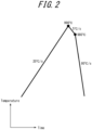
- the steel pipe or tube may be heated to the maximum heating temperature T, held (soaked) at the maximum heating temperature, and then cooled, as in typical normalizing.
- the conditions of the cooling are not limited, and may be determined depending on the chemical composition of the steel pipe or tube and the heating temperature.
- the average cooling rate from the cooling start to 650 °C is preferably 10 °C/s or less. If the average cooling rate from the cooling start to 650 °C is 10 °C/s or less, microstructure composed of one or both of ferrite and pearlite and containing no hard phase can be obtained.
- the steel pipe or tube in the cooling, is preferably cooled in the below-described first atmosphere or second atmosphere at least until 650 °C is reached, and more preferably cooled in the below-described first atmosphere or second atmosphere at least until 450 °C is reached.
- the normalizing can be performed using any line, as long as the claimed atmosphere is used.
- a continuous-type heat treatment furnace (continuous furnace) is preferably used.
- a bright annealing furnace commonly used for bright annealing is preferably used for the heat treatment.
- the normalizing needs to be performed in an atmosphere that does not cause decarburization. If the atmosphere is not appropriate, decarburization of the base metal portion which is a supply source of carbon for carbon restoration to the electric resistance weld portion progresses, and carbon restoration to the electric resistance weld portion does not progress. Examples of the atmosphere that does not cause decarburization refer to the following two atmospheres.
- G C ⁇ is the free energy of C in austenite phase
- G C gr is the free energy of C in graphite
- ⁇ FeC ⁇ is an interaction coefficient between C and Fe in austenite phase
- W MC ⁇ is an interaction coefficient between C and element A in austenite phase.
- the reason that the parameters in austenite phase are used is because, when the steel pipe or tube formed by the steel sheet having the claimed chemical composition is subjected to normalizing, the microstructure of the steel becomes a microstructure substantially composed of austenite single phase. Accordingly, the mole fractions of C, Si, Mn, and Cr in austenite phase are equal to the mole fractions of the respective elements in the steel. Thus, in the calculation of Formulas (3) and (4), the values of the mole fractions in the steel can be used as the mole fractions in austenite phase. Moreover, since austenite single phase is formed as a result of the normalizing as mentioned above, the microstructure of the steel before the normalizing can be any microstructure.
- the method of preparing the atmosphere is not limited, and may be any method.
- the atmosphere can be prepared by removing CO 2 and H 2 O from gas obtained by incompletely combusting methane, propane, or the like.
- the gas neutral to C and Fe for example, one or both of N 2 and Ar may be used.
- the normalizing is performed in an atmosphere that contains, in mole fraction, H 2 : 0 % to 10 % and O 2 : 80 ppm or less with the balance consisting of H 2 O and N 2 and has a dew point of 0 °C or less.
- H 2 is a component that can be added optionally, and its mole fraction may be 0.
- H 2 is a component having an effect of suppressing oxidation or decarburization of the steel pipe or tube, and therefore is preferably added.
- the mole fraction of H 2 is preferably 1 % or more, and more preferably 2 % or more. If H 2 is added excessively, the additive effect is saturated, and an explosion tends to occur.
- the mole fraction of H 2 is therefore 10 % or less, preferably 7 % or less, and more preferably 5 % or less.
- O 2 and H 2 O are components that cause decarburization.
- O 2 and H 2 O also oxidize iron to form oxide scale, and, in the case where oxidation is significant, cause a decrease in surface properties such as an increase of surface roughness.
- the amounts of O 2 and H 2 O in the atmosphere are therefore desirably low. Specifically, if the mole fraction of O 2 is more than 80 ppm, these adverse effects are noticeable.
- the mole fraction of O 2 is therefore 80 ppm or less, preferably 40 ppm or less, and more preferably 20 ppm or less.
- H 2 O if the dew point is more than 0 °C, the adverse effects are noticeable.
- the dew point is therefore 0 °C or less, preferably -20 °C or less, and more preferably -40 °C or less. In terms of easiness of atmosphere adjustment, the dew point is preferably -60 °C or more, and more preferably -50 °C or more.
- the depth of the total decarburized layer in each of the inner surface layer and the outer surface layer of the electric resistance welded steel pipe or tube after the normalizing can be limited to 50 ⁇ 10 -6 m or less.
- the electric resistance welded steel pipe or tube according to the present invention can be produced according to the procedure described above.
- the electric resistance welded steel pipe or tube obtained in this way has excellent fatigue durability after rapid and short-time heating quenching treatment, and is suitable for use as material of a hollow stabilizer and the like.
- the electric resistance welded steel pipe or tube produced in the foregoing method can be used for any applications.
- the electric resistance welded steel pipe or tube can be used as material of a hollow part such as a hollow stabilizer as mentioned above.
- the electric resistance welded steel pipe or tube into a desired member shape and then subject the electric resistance welded steel pipe or tube to rapid and short-time heating quenching treatment.
- the working may be any working, but cold working is preferably used.
- the rapid and short-time heating quenching treatment is performed under the conditions that the maximum heating temperature is 900 °C or more, the average heating rate from the room temperature to the maximum heating temperature is 10 °C/s or more, and the residence time in a temperature range of 900 °C or more is 1 min or less.
- the heating in the quenching may be performed by any method, such as high-frequency heating or electrical resistance heating.
- the quenching start temperature Tq in the rapid and short-time heating quenching treatment is higher than the Ar3 transformation point of the electric resistance weld portion. If Tq is not higher than the Ar3 transformation point of the electric resistance weld portion, ferrite transformation or bainite transformation occurs before the start of quenching (rapid cooling), as a result of which the electric resistance weld portion cannot have a microstructure composed of 100 % martensite. Consequently, the desired quenching hardness cannot be ensured, and the fatigue durability decreases.
- the Ar3 transformation point of the electric resistance weld portion is a value calculated according to the following Formula (5). This value deviates from the actual Ar3 transformation point to the high temperature side, and thus is a value on the safe side in the determination of the rapid cooling start temperature.
- the calculation formula of the Ac3 transformation point is quoted from William C. Leslie, The Physical Metallurgy of Steels (trans. by N. Koda: 1985, Maruzen, p. 273).
- the cooling rate in the quenching may be any cooling condition with which 100 % martensite microstructure can be formed.
- the cooling condition with which 100 % martensite microstructure is obtained depends on the chemical composition of the steel sheet as the material, in the present invention, it is preferable to cool the electric resistance welded steel pipe or tube from the quenching start temperature Tq to the room temperature at an average cooling rate of 30 °C/s or more and preferably 80 °C/s or more.
- the rapid cooling (secondary cooling) in the quenching treatment is preferably performed using a coolant such as water or a mixture of water and a polymer, in terms of productivity and maintenance.
- a coolant such as water or a mixture of water and a polymer
- oil quenching may be used.
- tempering treatment to improve toughness may be optionally performed.
- the heating temperature (tempering temperature) in the tempering treatment is preferably 150 °C to 450 °C. If the heating temperature is less than 150 °C, the desired toughness may not be ensured. If the heating temperature is more than 450 °C, the hardness may decrease and the desired durability may not be ensured.
- electric resistance welded steel pipes or tubes were produced according to the following procedure. First, each hot-rolled steel sheet was pickled, and scale was removed. The hot-rolled steel sheet was then subjected to continuous cold roll forming, to obtain an approximately cylindrical open pipe or tube. The ends of the open pipe or tube were then butted together, and electric resistance welding was performed by high frequency resistance welding to obtain an electric resistance welded steel pipe or tube. The obtained electric resistance welded steel pipe or tube had an outer diameter of 25.4 mm and a thickness of 4.5 mm.
- the welding conditions were changed to adjust the bond width of the electric resistance weld portion to the value listed in Tables 2 and 3.
- the bond width was determined by collecting a test piece for microstructure observation including the electric resistance weld portion from the obtained electric resistance welded steel pipe or tube and performing microstructure observation.
- the test piece for microstructure observation was cut out so that a cross-section perpendicular to the longitudinal (pipe or tube axial) direction of the electric resistance welded steel pipe or tube was the observation plane.
- the cross-section of the cut test piece was polished.
- the surface of the test piece after the polishing was etched using a metal flow etching solution (5 % picric acid + surfactant). After this, the cross-sectional microstructure was observed using an optical microscope (magnification: 400 times). The maximum width of a region (layer) in which no segregation line was observed in the cross-sectional microstructure was measured and taken to be the bond width.
- the surface of the test piece after the polishing was etched using a nital etching solution (5 % nitric acid alcohol). After this, the cross-sectional microstructure was observed using an optical microscope (magnification: 400 times). The maximum width of a region (white layer) observed bright in the cross-sectional microstructure was measured and taken to be the bond width.
- the depth of the total decarburized layer in each of the inner surface layer and the outer surface layer was measured in accordance with the "microscopic measurement method" defined in JIS G 0558 "Steels-Determination of depth of decarburization".
- the electric resistance welded steel pipe or tube was cut at the center in the longitudinal direction, and the maximum value of the decarburized layer depth in the cross-section was adopted.
- the depth of the decarburized ferrite layer was also measured by the same method. The measurement results are listed in Tables 2 and 3.
- the electric resistance welded steel pipe or tube (as electric resistance welded) after the electric resistance welding was then subjected to normalizing under the conditions listed in Tables 2 and 3.
- the normalizing included the following processes (1) to (3):
- t (s) defined as the time during which the steel pipe or tube was held in a temperature range of (T - 50 K) to T in the processes (1) to (3) is as listed in Tables 2 and 3.
- the maximum heating temperature T was expressed not in absolute temperature (K) but in degree Celsius (°C), for the sake of convenience.
- C* 1 (mass%) which is a calculated value of the minimum C content of the electric resistance weld portion was calculated according to Formula (2).
- the obtained value of C* 1 and the value of C 0 - C* 1 i.e. the difference between C* 1 and C 0 which is the C content of the steel sheet, are listed in Tables 2 and 3.
- C 0 which is the C content of the steel sheet the value of the C content in Table 1 was used.
- the atmosphere in Table 4 corresponds to the first atmosphere, and is composed of CO, CO 2 , H 2 , H 2 O, and N 2 .
- N 2 is a gas neutral to C and Fe.
- the atmosphere in Table 5 corresponds to the second atmosphere, and is composed of H 2 , O 2 , H 2 O, and the balance consisting of N 2 . In Table 5, the amount of H 2 O is shown as dew point.
- C 1 mass% which is the minimum C content of the electric resistance weld portion was measured.
- the measurement method is as follows. The measurement was performed before the below-described quenching treatment.
- the C content in the electric resistance weld portion of the obtained electric resistance welded steel pipe or tube was determined based on the result of EPMA measurement.
- the measurement position was a position of 200 ⁇ m (depth: 200 ⁇ m) in the thickness direction from the outer surface in a cross-section perpendicular to the longitudinal direction of the steel pipe or tube and including the electric resistance weld portion.
- the measurement was performed according to the following procedure. First, a sample was cut out of the electric resistance welded steel pipe or tube so that a cross-section perpendicular to the longitudinal direction was the measurement position. Next, the cross-section was subjected to EPMA measurement in lines of bond width + 200 ⁇ m in length in the circumferential direction centering at the bond portion, to measure the X-ray intensity derived from C.
- the average value A of X-ray intensities in a range of ⁇ (bond width ⁇ 0.4) centering at the bond portion in the lines was calculated.
- the average value B of X-ray intensities in a range of a position 20 ⁇ m away from the end of the bond portion to a position 80 ⁇ m away from the end of the bond portion in the lines was calculated.
- the measurement position of the average intensity B corresponds to the base metal portion.
- C 1 which is the minimum C content of the electric resistance weld portion was calculated as the C content of the steel sheet: C 0 ⁇ (average value of A)/(average value of B).
- C 0 - C 1 The value of C 0 - C 1 , i.e. the difference between C 1 which is the obtained minimum C content of the electric resistance weld portion and C 0 which is the C content of the steel sheet, is listed in Tables 6 and 7. As C 0 which is the C content of the steel sheet, the value of the C content in Table 1 was used. Each measured value of C 0 - C 1 in Tables 6 and 7 closely matches the calculated value of C 0 - C* 1 in Tables 2 and 3, except Comparative Examples Nos. 7 to 9, 21, and 22 in which the normalizing atmosphere was outside the range according to the present disclosure and decarburization progressed. This demonstrates that, in the case where the normalizing atmosphere is within the range according to the present disclosure, the minimum C content of the electric resistance weld portion after the normalizing can be estimated using Formula (2).
- Hv 0 which is the Vickers hardness in the base metal portion
- Hv 1 which is the Vickers hardness in the electric resistance weld portion
- a test piece for hardness measurement was collected from the obtained electric resistance welded steel pipe or tube, and the Vickers hardness (HV0.5) of each of the electric resistance weld portion and the base metal portion was measured in the sheet thickness direction by a Vickers hardness meter (load: 4.9 N). The measurement was performed at a 0.2 mm pitch in a range of 1 mm from each of the outer surface and the inner surface, and an arithmetic mean of the obtained values was taken to be the hardness in each of the electric resistance weld portion and the base metal portion of the steel pipe or tube.
- the electric resistance welded steel pipe or tube after the quenching was further subjected to tempering for 20 min at the tempering temperature listed in Tables 6 and 7.
- Hv 0 which is the Vickers hardness in the base metal portion
- Hv 1 which is the Vickers hardness in the electric resistance weld portion were measured by the same method as for the electric resistance welded steel pipe or tube after the quenching. The measurement results are listed in Tables 6 and 7.
- a test material for a fatigue test (pipe or tube axial length: 250 mm) was collected from the electric resistance welded steel pipe or tube after the tempering, and subjected to a completely reversed torsional fatigue test in accordance with JIS Z 2273.
- stress ⁇ was 380 MPa for each steel pipe or tube using any of the steel sheets ID A, B, E, F, G, I, and J, and 470 MPa for each steel pipe or tube using any of the steel sheets ID C, D, and H.
- the fracture state was observed. The case where abnormal cracking along the electric resistance weld portion occurred was evaluated as poor, and the case where other cracking occurred was evaluated as good.
- the evaluation results and the number of repetitions Nf until fracture are listed in Tables 6 and 7.
- FIG. 3 is a graph illustrating the relationship between C 0 - C 1 and Hv 0 -Hv 1 , where C 0 - C 1 is the difference between C 1 (mass%) which is the minimum C content of the electric resistance weld portion and C 0 (mass%) which is the C content of the steel sheet, and Hv 0 -Hv 1 is the difference between Hv 1 which is the Vickers hardness of the electric resistance weld portion and Hv 0 which is the Vickers hardness of the base metal portion after the tempering.
- each white dot indicates the case where abnormal cracking along the electric resistance weld portion occurred in the torsional fatigue test
- each black dot indicates the case where no abnormal cracking along the electric resistance weld portion occurred in the torsional fatigue test.
- FIG. 4 is a graph in which the horizontal axis represents C 0 - C* 1 and the vertical axis represents C 0 - C 1 , where C 0 - C* 1 is the difference between C* 1 (mass%) which is the calculated value of the minimum C content of the electric resistance weld portion according to Formula (2) and C 0 (mass%) which is the C content of the steel sheet, and C 0 - C 1 is the measured value.
- C* 1 which is the minimum C content of the electric resistance weld portion calculated using Formula (2) closely matches C 1 which is the measured minimum C content of the electric resistance weld portion.
Landscapes
- Chemical & Material Sciences (AREA)
- Engineering & Computer Science (AREA)
- Mechanical Engineering (AREA)
- Materials Engineering (AREA)
- Metallurgy (AREA)
- Organic Chemistry (AREA)
- Physics & Mathematics (AREA)
- Thermal Sciences (AREA)
- Crystallography & Structural Chemistry (AREA)
- Heat Treatment Of Articles (AREA)
Claims (2)
- Tube ou tuyau en acier soudé par résistance électrique comprenant :
un métal de base qui est une tôle d'acier ayant une composition chimique constituée, en % en masse, de :C : 0,15 % à 0,40 %,Si : 0,05 % à 0,50 %,Mn : 0,30 % à 2,00 %,AI : 0,01 % à 0,10 %,Ti : 0,001 % à 0,04 %,B : 0,0005 % à 0,0050 %,N : 0,0010 % à 0,0100 %, etéventuellement, en % en masse, un ou plusieurs éléments choisis dans le groupe constitué parCr : 1,0 % ou moins,Mo : 1,0 % ou moins,W : 1,0 % ou moins,Ni : 1,0 % ou moins,Cu : 1,0 % ou moins,Nb : 0,2 % ou moins,V : 0,2 % ou moins, etCa : 0,0050 % ou moins,avec un reliquat constitué de Fe et d'impuretés inévitables, dans lequel P est égal ou inférieur à 0,020 %, S est égal ou inférieur à 0,010 % et O est égal ou inférieur à 0,005 %, une teneur en Ti et une teneur en N satisfaisant à la Formule (1) suivante, où N est la teneur en N en % en masse et Ti est la teneur en Ti en % en masse, etune partie de soudure par résistance électrique ayant une largeur de liaison de 40 × 10-6 m ou plus et 120 × 10-6 m ou moins, mesurée par la méthode selon la description,dans lequelC0 - C1 est égale ou inférieure à 0,05 % en masse, mesurée par le procédé selon la description, où C0 - C1 est une différence entre C1 en % en masse qui est une teneur minimum en C de la partie de soudure par résistance électrique et C0 en % en masse qui est une teneur en C de la tôle d'acier, etune profondeur d'une couche décarburée totale dans chacune d'une couche de surface interne et d'une couche de surface externe du tube ou du tuyau en acier soudé par résistance électrique, mesurée par la méthode selon la description, est égale ou inférieure à 50 × 10-6 m.
 - Procédé de production d'un tube ou d'un tuyau en acier soudé par résistance électrique, le procédé comprenant :le soudage par résistance électrique d'une tôle d'acier pour former un tube ou un tuyau en acier soudé par résistance électrique qui comporte une partie de soudure par résistance électrique ayant une largeur de liaison de 40 × 10-6 m ou plus et 120 × 10-6 m ou moins et dans lequel une profondeur d'une couche décarburée totale dans chacune d'une couche de surface interne et d'une couche de surface externe est égale ou inférieure à 50 × 10-6 m, la tôle d'acier ayant une composition chimique constituée, en % en masse, deC : 0,15 % à 0,40 %,Si : 0,05 % à 0,50 %,Mn : 0,30 % à 2,00 %,AI : 0,01 % à 0,10 %,Ti : 0,001 % à 0,04 %,B : 0,0005 % à 0,0050 % etN : 0,0010 % à 0,0100 %éventuellement, en % en masse, un ou plusieurs éléments choisis dans le groupe constitué parCr : 1,0 % ou moins,Mo : 1,0 % ou moins,W : 1,0 % ou moins,Ni : 1,0 % ou moins,Cu : 1,0 % ou moins,Nb : 0,2 % ou moins,V : 0,2 % ou moins, etCa : 0,0050 % ou moins,avec un reliquat constitué de Fe et d'impuretés inévitables, dans lequel P est égal ou inférieur à 0,020 %, S est égal ou inférieur à 0,010 % et O est égal ou inférieur à 0,005 %, une teneur en Ti et une teneur en N satisfaisant à la Formule (1) suivante,
 où N est la teneur en N en % en masse et Ti est la teneur en Ti en % en masse ;
etaprès cela la normalisation du tube ou du tuyau en acier soudé par résistance électrique dans des conditions telles que C0 - C*1 est égale ou inférieure à 0,05 % en masse, où C0 - C*1 est une différence entre C*1 et C0, C0 en % en masse est une teneur en C de la tôle d'acier et C*1 en % en masse est une valeur calculée d'une teneur minimum en C de la partie de soudure par résistance électrique selon la Formule (2) suivante oùC0 est la teneur en C en % en masse de la tôle d'acier,
 h est la largeur de liaison divisée par 2 et exprimée en mètres,D exprimée en m2/s = D0 exp(-Q/RT),

 T est une température de chauffage maximale en Kelvin pendant la normalisation, ett est un temps exprimé en secondes pendant lequel le tube ou le tuyau en acier soudé par résistance électrique est maintenu dans une plage de température de (T - 50 K) à T pendant la normalisation, et où la normalisation est en outre effectuée dans une première atmosphère ou une seconde atmosphère, où la première atmosphère est composée de CO, CO2, H2, H2O et d'un gaz neutre vis-à-vis de C et Fe et satisfait aux formules (3) et (4) suivantes,


 Pco est une pression partielle exprimée en atm de CO dans une atmosphère de four,PCO2 est une pression partielle exprimée en atm de CO2 dans l'atmosphère de four,PH2 est une pression partielle exprimée en atm de H2 dans l'atmosphère de four,PH2O est une pression partielle exprimée en atm de H2O dans l'atmosphère de four,R = 8,31 J/mol·K,T est la température de chauffage maximale en Kelvin pendant la normalisation,aC γ est une activité de C dans la phase austénite,xC γ est une fraction molaire de C dans la phase austénite,xSi γ est une fraction molaire de Si dans la phase austénite,xMn γ est une fraction molaire de Mn dans la phase austénite,xCr γ est une fraction molaire de Cr dans la phase austénite,GC γ est une énergie libre de C dans la phase austénite,GC gr est une énergie libre de C dans le graphite, et oùla seconde atmosphère est composée, en fraction molaire dans une atmosphère de four, de H2 : 0 % à 10 % et O2 : 80 ppm ou moins, avec un reliquat constitué de H2O et de N2 et a un point de rosée de 0 °C ou moins.
Applications Claiming Priority (2)
| Application Number | Priority Date | Filing Date | Title |
|---|---|---|---|
| JP2017251999 | 2017-12-27 | ||
| PCT/JP2018/047972 WO2019131813A1 (fr) | 2017-12-27 | 2018-12-26 | Tuyau en acier soudé par résistance électrique et son procédé de fabrication |
Publications (4)
| Publication Number | Publication Date |
|---|---|
| EP3733894A1 EP3733894A1 (fr) | 2020-11-04 |
| EP3733894A4 EP3733894A4 (fr) | 2020-11-04 |
| EP3733894B1 true EP3733894B1 (fr) | 2024-04-03 |
| EP3733894B8 EP3733894B8 (fr) | 2024-05-29 |
Family
ID=67067488
Family Applications (1)
| Application Number | Title | Priority Date | Filing Date |
|---|---|---|---|
| EP18894950.7A Active EP3733894B8 (fr) | 2017-12-27 | 2018-12-26 | Tube ou tuyau en acier soudé par résistance électrique et méthode de production d'un tube ou d'un tuyau en acier soudé par résistance électrique |
Country Status (6)
| Country | Link |
|---|---|
| US (2) | US11512361B2 (fr) |
| EP (1) | EP3733894B8 (fr) |
| JP (1) | JP6649531B2 (fr) |
| KR (1) | KR102390423B1 (fr) |
| CN (1) | CN111511946B (fr) |
| WO (1) | WO2019131813A1 (fr) |
Families Citing this family (9)
| Publication number | Priority date | Publication date | Assignee | Title |
|---|---|---|---|---|
| WO2020129337A1 (fr) * | 2018-12-19 | 2020-06-25 | Jfeスチール株式会社 | Tuyau en acier soudé par résistance électrique |
| TWI697563B (zh) * | 2019-09-26 | 2020-07-01 | 中國鋼鐵股份有限公司 | 鋼胚加熱爐及抑制鋼胚表面脫碳層之厚度增加的方法 |
| WO2022065223A1 (fr) * | 2020-09-24 | 2022-03-31 | Ntn株式会社 | Cage soudée pour roulement à rouleaux, rouleau à cage, procédé de discrimination de partie de jonction soudée et procédé d'examen de qualité de cage soudée pour roulement à rouleaux |
| JP7783712B2 (ja) * | 2021-09-06 | 2025-12-10 | Ntn株式会社 | ころ軸受用溶接保持器、保持器付きころ、溶融接合部の判別方法、およびころ軸受用溶接保持器の品質確認方法 |
| JP7597540B2 (ja) * | 2020-09-24 | 2024-12-10 | Ntn株式会社 | ころ軸受用溶接保持器、保持器付きころ、および軸受用溶接保持器の検査方法 |
| CN112522607A (zh) * | 2020-11-17 | 2021-03-19 | 马鞍山钢铁股份有限公司 | 一种q125钢级sew石油套管及其制造方法 |
| KR102492994B1 (ko) | 2020-12-18 | 2023-01-30 | 주식회사 포스코 | 균일한 인장재질 및 용접부 횡크랙 저항성이 우수한 강판, 강관 및 이들의 제조방법 |
| JP7472826B2 (ja) * | 2021-03-03 | 2024-04-23 | Jfeスチール株式会社 | 電縫溶接鋼管およびその製造方法 |
| JP7001213B1 (ja) * | 2021-06-07 | 2022-01-19 | 日本製鉄株式会社 | 機械構造部品用電縫鋼管及びその製造方法 |
Family Cites Families (13)
| Publication number | Priority date | Publication date | Assignee | Title |
|---|---|---|---|---|
| JPS57126917A (en) | 1981-01-30 | 1982-08-06 | Nisshin Steel Co Ltd | Production of hollow stabilizer |
| JPS58123858A (ja) | 1982-01-16 | 1983-07-23 | Nisshin Steel Co Ltd | 中空状スタビライザ−用電縫鋼管用鋼 |
| JPS6145688A (ja) | 1984-08-08 | 1986-03-05 | Sharp Corp | ビデオデイスク再生装置 |
| JPH0787861B2 (ja) | 1987-08-28 | 1995-09-27 | 田中貴金属工業株式会社 | 医療用貴金属網の製造方法 |
| JPH05117809A (ja) * | 1990-12-29 | 1993-05-14 | Nkk Corp | 電縫部機械的性質の優れたドアインパクトバー用高強度電縫鋼管 |
| JP2814882B2 (ja) | 1992-07-27 | 1998-10-27 | 住友金属工業株式会社 | 高強度高延性電縫鋼管の製造方法 |
| JPH07266837A (ja) * | 1994-03-29 | 1995-10-17 | Horikiri Bane Seisakusho:Kk | 中空スタビライザの製造法 |
| JP2007056283A (ja) | 2005-08-22 | 2007-03-08 | Nippon Steel Corp | 焼入れ性及び耐脱炭性に優れた高強度厚肉電縫溶接鋼管およびその製造方法 |
| JP5303842B2 (ja) | 2007-02-26 | 2013-10-02 | Jfeスチール株式会社 | 偏平性に優れた熱処理用電縫溶接鋼管の製造方法 |
| JP5353256B2 (ja) * | 2008-01-21 | 2013-11-27 | Jfeスチール株式会社 | 中空部材およびその製造方法 |
| JP5845623B2 (ja) | 2010-05-27 | 2016-01-20 | Jfeスチール株式会社 | 耐ねじり疲労特性に優れた電縫鋼管及びその製造方法 |
| EP2952601B1 (fr) | 2013-01-31 | 2017-09-27 | JFE Steel Corporation | Tube d'acier soudé par résistance électrique |
| EP3476953B1 (fr) * | 2016-10-24 | 2022-01-05 | JFE Steel Corporation | Tuyau en acier soudé par résistance électrique destiné à un stabilisateur creux mince à haute résistance et son procédé de fabrication |
-
2018
- 2018-12-26 JP JP2019533138A patent/JP6649531B2/ja active Active
- 2018-12-26 KR KR1020207021308A patent/KR102390423B1/ko active Active
- 2018-12-26 US US16/958,736 patent/US11512361B2/en active Active
- 2018-12-26 EP EP18894950.7A patent/EP3733894B8/fr active Active
- 2018-12-26 CN CN201880084274.XA patent/CN111511946B/zh active Active
- 2018-12-26 WO PCT/JP2018/047972 patent/WO2019131813A1/fr not_active Ceased
-
2022
- 2022-10-18 US US18/047,331 patent/US12234524B2/en active Active
Also Published As
| Publication number | Publication date |
|---|---|
| US20200332381A1 (en) | 2020-10-22 |
| US20230079323A1 (en) | 2023-03-16 |
| CN111511946B (zh) | 2021-12-07 |
| WO2019131813A1 (fr) | 2019-07-04 |
| JP6649531B2 (ja) | 2020-02-19 |
| EP3733894A1 (fr) | 2020-11-04 |
| EP3733894A4 (fr) | 2020-11-04 |
| US12234524B2 (en) | 2025-02-25 |
| CN111511946A (zh) | 2020-08-07 |
| KR20200096652A (ko) | 2020-08-12 |
| EP3733894B8 (fr) | 2024-05-29 |
| KR102390423B1 (ko) | 2022-04-22 |
| US11512361B2 (en) | 2022-11-29 |
| JPWO2019131813A1 (ja) | 2019-12-26 |
Similar Documents
| Publication | Publication Date | Title |
|---|---|---|
| EP3733894B1 (fr) | Tube ou tuyau en acier soudé par résistance électrique et méthode de production d'un tube ou d'un tuyau en acier soudé par résistance électrique | |
| EP2540854B1 (fr) | Feuille d'acier laminée à froid de super-haute résistance ayant d'excellentes propriétés de flexion | |
| EP2692890B1 (fr) | Tôle d'acier ou feuille d'acier et son procédé de fabrication | |
| EP2239343B1 (fr) | Elément creux et procédé pour sa fabrication | |
| EP2695960B1 (fr) | Tôle d'acier résistant à l'abrasion qui présente une excellente résistance à une fissuration par corrosion sous tension et procédé de production de cette dernière | |
| EP3128029B1 (fr) | Matériau en acier destiné à des tuyaux de canalisation fortement déformables et présentant des caractéristiques de vieillissement après déformation et des caractéristiques anti-hic supérieures, son procédé de fabrication et tuyau en acier soudé | |
| JP5928405B2 (ja) | 耐水素誘起割れ性に優れた調質鋼板及びその製造方法 | |
| EP3604592B1 (fr) | Plaque d'acier haute résistance pour tuyau de canalisation résistant à l'acidité, son procédé de fabrication, et tuyau en acier haute résistance utilisant une plaque d'acier haute résistance pour tuyau de canalisation résistant à l'acidité | |
| WO2015151468A1 (fr) | Matériau en acier pour tuyaux de canalisation hautement déformables ayant des caractéristiques de vieillissement après déformation et caractéristiques anti-hic supérieures, procédé de fabrication de ce dernier et tuyau en acier soudé | |
| EP4458993A1 (fr) | Tôle en acier, et procédé de fabrication de celle-ci | |
| JP6796472B2 (ja) | 中空部材及びその製造方法 | |
| EP3971307B1 (fr) | Tuyau en acier soudé par résistance électrique pour stabilisateur creux | |
| JP2009235499A (ja) | 中空スタビライザーの製造方法 | |
| EP2891725B1 (fr) | Tuyau d'acier sans soudure et son procédé de fabrication | |
| CN115298340A (zh) | 耐酸管线用高强度钢板及其制造方法以及使用耐酸管线用高强度钢板的高强度钢管 | |
| EP4043594A1 (fr) | Tôle en acier hautement résistante ainsi que procédé de fabrication de celle-ci, et élément d'absorption de chocs | |
| JP7754273B2 (ja) | 耐水素脆化特性に優れたラインパイプ用鋼管、その製造方法、ラインパイプ用鋼材およびその製造方法 | |
| EP4675003A1 (fr) | Tuyau d'acier et son procédé de fabrication | |
| EP4502220A1 (fr) | Tôle d'acier haute résistance pour un tuyau de canalisation résistant à l'acidité, ainsi que son procédé de production, et tuyau en acier haute résistance utilisant une tôle d'acier haute résistance pour un tuyau de canalisation résistant à l'acidité | |
| JP4765680B2 (ja) | 焼戻し効率性および焼戻し安定性に優れるマルテンサイト系ステンレス鋼 | |
| WO2023162507A1 (fr) | Tôle en acier, et procédé de fabrication de celle-ci | |
| CN117280062A (zh) | 机械结构部件用电焊钢管及其制造方法 |
Legal Events
| Date | Code | Title | Description |
|---|---|---|---|
| STAA | Information on the status of an ep patent application or granted ep patent |
Free format text: STATUS: THE INTERNATIONAL PUBLICATION HAS BEEN MADE |
|
| PUAI | Public reference made under article 153(3) epc to a published international application that has entered the european phase |
Free format text: ORIGINAL CODE: 0009012 |
|
| STAA | Information on the status of an ep patent application or granted ep patent |
Free format text: STATUS: REQUEST FOR EXAMINATION WAS MADE |
|
| 17P | Request for examination filed |
Effective date: 20200626 |
|
| A4 | Supplementary search report drawn up and despatched |
Effective date: 20200925 |
|
| AK | Designated contracting states |
Kind code of ref document: A1 Designated state(s): AL AT BE BG CH CY CZ DE DK EE ES FI FR GB GR HR HU IE IS IT LI LT LU LV MC MK MT NL NO PL PT RO RS SE SI SK SM TR |
|
| AX | Request for extension of the european patent |
Extension state: BA ME |
|
| DAV | Request for validation of the european patent (deleted) | ||
| DAX | Request for extension of the european patent (deleted) | ||
| GRAJ | Information related to disapproval of communication of intention to grant by the applicant or resumption of examination proceedings by the epo deleted |
Free format text: ORIGINAL CODE: EPIDOSDIGR1 |
|
| STAA | Information on the status of an ep patent application or granted ep patent |
Free format text: STATUS: GRANT OF PATENT IS INTENDED |
|
| GRAP | Despatch of communication of intention to grant a patent |
Free format text: ORIGINAL CODE: EPIDOSNIGR1 |
|
| INTG | Intention to grant announced |
Effective date: 20231012 |
|
| RIN1 | Information on inventor provided before grant (corrected) |
Inventor name: GUNJI, MAKIO Inventor name: KAWABATA, YOSHIKAZU |
|
| GRAS | Grant fee paid |
Free format text: ORIGINAL CODE: EPIDOSNIGR3 |
|
| GRAA | (expected) grant |
Free format text: ORIGINAL CODE: 0009210 |
|
| STAA | Information on the status of an ep patent application or granted ep patent |
Free format text: STATUS: THE PATENT HAS BEEN GRANTED |
|
| AK | Designated contracting states |
Kind code of ref document: B1 Designated state(s): AL AT BE BG CH CY CZ DE DK EE ES FI FR GB GR HR HU IE IS IT LI LT LU LV MC MK MT NL NO PL PT RO RS SE SI SK SM TR |
|
| REG | Reference to a national code |
Ref country code: GB Ref legal event code: FG4D |
|
| REG | Reference to a national code |
Ref country code: CH Ref legal event code: EP |
|
| REG | Reference to a national code |
Ref country code: DE Ref legal event code: R081 Ref document number: 602018067687 Country of ref document: DE Owner name: JFE STEEL CORPORATION, JP Free format text: FORMER OWNERS: JFE STEEL CORPORATION, TOKYO, JP; JFE WELDED PIPE MANUFACTURING CO., LTD., TOKYO, JP |
|
| REG | Reference to a national code |
Ref country code: IE Ref legal event code: FG4D |
|
| REG | Reference to a national code |
Ref country code: DE Ref legal event code: R096 Ref document number: 602018067687 Country of ref document: DE |
|
| RAP2 | Party data changed (patent owner data changed or rights of a patent transferred) |
Owner name: JFE STEEL CORPORATION |
|
| REG | Reference to a national code |
Ref country code: CH Ref legal event code: PK Free format text: BERICHTIGUNG B8 |
|
| REG | Reference to a national code |
Ref country code: LT Ref legal event code: MG9D |
|
| REG | Reference to a national code |
Ref country code: NL Ref legal event code: MP Effective date: 20240403 |
|
| REG | Reference to a national code |
Ref country code: AT Ref legal event code: MK05 Ref document number: 1672380 Country of ref document: AT Kind code of ref document: T Effective date: 20240403 |
|
| PG25 | Lapsed in a contracting state [announced via postgrant information from national office to epo] |
Ref country code: NL Free format text: LAPSE BECAUSE OF FAILURE TO SUBMIT A TRANSLATION OF THE DESCRIPTION OR TO PAY THE FEE WITHIN THE PRESCRIBED TIME-LIMIT Effective date: 20240403 |
|
| PG25 | Lapsed in a contracting state [announced via postgrant information from national office to epo] |
Ref country code: NL Free format text: LAPSE BECAUSE OF FAILURE TO SUBMIT A TRANSLATION OF THE DESCRIPTION OR TO PAY THE FEE WITHIN THE PRESCRIBED TIME-LIMIT Effective date: 20240403 |
|
| PG25 | Lapsed in a contracting state [announced via postgrant information from national office to epo] |
Ref country code: IS Free format text: LAPSE BECAUSE OF FAILURE TO SUBMIT A TRANSLATION OF THE DESCRIPTION OR TO PAY THE FEE WITHIN THE PRESCRIBED TIME-LIMIT Effective date: 20240803 |
|
| PG25 | Lapsed in a contracting state [announced via postgrant information from national office to epo] |
Ref country code: BG Free format text: LAPSE BECAUSE OF FAILURE TO SUBMIT A TRANSLATION OF THE DESCRIPTION OR TO PAY THE FEE WITHIN THE PRESCRIBED TIME-LIMIT Effective date: 20240403 |
|
| PG25 | Lapsed in a contracting state [announced via postgrant information from national office to epo] |
Ref country code: FI Free format text: LAPSE BECAUSE OF FAILURE TO SUBMIT A TRANSLATION OF THE DESCRIPTION OR TO PAY THE FEE WITHIN THE PRESCRIBED TIME-LIMIT Effective date: 20240403 Ref country code: HR Free format text: LAPSE BECAUSE OF FAILURE TO SUBMIT A TRANSLATION OF THE DESCRIPTION OR TO PAY THE FEE WITHIN THE PRESCRIBED TIME-LIMIT Effective date: 20240403 |
|
| PG25 | Lapsed in a contracting state [announced via postgrant information from national office to epo] |
Ref country code: GR Free format text: LAPSE BECAUSE OF FAILURE TO SUBMIT A TRANSLATION OF THE DESCRIPTION OR TO PAY THE FEE WITHIN THE PRESCRIBED TIME-LIMIT Effective date: 20240704 |
|
| PG25 | Lapsed in a contracting state [announced via postgrant information from national office to epo] |
Ref country code: PT Free format text: LAPSE BECAUSE OF FAILURE TO SUBMIT A TRANSLATION OF THE DESCRIPTION OR TO PAY THE FEE WITHIN THE PRESCRIBED TIME-LIMIT Effective date: 20240805 |
|
| PG25 | Lapsed in a contracting state [announced via postgrant information from national office to epo] |
Ref country code: ES Free format text: LAPSE BECAUSE OF FAILURE TO SUBMIT A TRANSLATION OF THE DESCRIPTION OR TO PAY THE FEE WITHIN THE PRESCRIBED TIME-LIMIT Effective date: 20240403 |
|
| PG25 | Lapsed in a contracting state [announced via postgrant information from national office to epo] |
Ref country code: CZ Free format text: LAPSE BECAUSE OF FAILURE TO SUBMIT A TRANSLATION OF THE DESCRIPTION OR TO PAY THE FEE WITHIN THE PRESCRIBED TIME-LIMIT Effective date: 20240403 |
|
| PG25 | Lapsed in a contracting state [announced via postgrant information from national office to epo] |
Ref country code: AT Free format text: LAPSE BECAUSE OF FAILURE TO SUBMIT A TRANSLATION OF THE DESCRIPTION OR TO PAY THE FEE WITHIN THE PRESCRIBED TIME-LIMIT Effective date: 20240403 |
|
| PG25 | Lapsed in a contracting state [announced via postgrant information from national office to epo] |
Ref country code: PL Free format text: LAPSE BECAUSE OF FAILURE TO SUBMIT A TRANSLATION OF THE DESCRIPTION OR TO PAY THE FEE WITHIN THE PRESCRIBED TIME-LIMIT Effective date: 20240403 |
|
| PG25 | Lapsed in a contracting state [announced via postgrant information from national office to epo] |
Ref country code: LV Free format text: LAPSE BECAUSE OF FAILURE TO SUBMIT A TRANSLATION OF THE DESCRIPTION OR TO PAY THE FEE WITHIN THE PRESCRIBED TIME-LIMIT Effective date: 20240403 |
|
| PG25 | Lapsed in a contracting state [announced via postgrant information from national office to epo] |
Ref country code: PT Free format text: LAPSE BECAUSE OF FAILURE TO SUBMIT A TRANSLATION OF THE DESCRIPTION OR TO PAY THE FEE WITHIN THE PRESCRIBED TIME-LIMIT Effective date: 20240805 Ref country code: PL Free format text: LAPSE BECAUSE OF FAILURE TO SUBMIT A TRANSLATION OF THE DESCRIPTION OR TO PAY THE FEE WITHIN THE PRESCRIBED TIME-LIMIT Effective date: 20240403 Ref country code: NO Free format text: LAPSE BECAUSE OF FAILURE TO SUBMIT A TRANSLATION OF THE DESCRIPTION OR TO PAY THE FEE WITHIN THE PRESCRIBED TIME-LIMIT Effective date: 20240703 Ref country code: LV Free format text: LAPSE BECAUSE OF FAILURE TO SUBMIT A TRANSLATION OF THE DESCRIPTION OR TO PAY THE FEE WITHIN THE PRESCRIBED TIME-LIMIT Effective date: 20240403 Ref country code: IS Free format text: LAPSE BECAUSE OF FAILURE TO SUBMIT A TRANSLATION OF THE DESCRIPTION OR TO PAY THE FEE WITHIN THE PRESCRIBED TIME-LIMIT Effective date: 20240803 Ref country code: HR Free format text: LAPSE BECAUSE OF FAILURE TO SUBMIT A TRANSLATION OF THE DESCRIPTION OR TO PAY THE FEE WITHIN THE PRESCRIBED TIME-LIMIT Effective date: 20240403 Ref country code: GR Free format text: LAPSE BECAUSE OF FAILURE TO SUBMIT A TRANSLATION OF THE DESCRIPTION OR TO PAY THE FEE WITHIN THE PRESCRIBED TIME-LIMIT Effective date: 20240704 Ref country code: FI Free format text: LAPSE BECAUSE OF FAILURE TO SUBMIT A TRANSLATION OF THE DESCRIPTION OR TO PAY THE FEE WITHIN THE PRESCRIBED TIME-LIMIT Effective date: 20240403 Ref country code: ES Free format text: LAPSE BECAUSE OF FAILURE TO SUBMIT A TRANSLATION OF THE DESCRIPTION OR TO PAY THE FEE WITHIN THE PRESCRIBED TIME-LIMIT Effective date: 20240403 Ref country code: CZ Free format text: LAPSE BECAUSE OF FAILURE TO SUBMIT A TRANSLATION OF THE DESCRIPTION OR TO PAY THE FEE WITHIN THE PRESCRIBED TIME-LIMIT Effective date: 20240403 Ref country code: BG Free format text: LAPSE BECAUSE OF FAILURE TO SUBMIT A TRANSLATION OF THE DESCRIPTION OR TO PAY THE FEE WITHIN THE PRESCRIBED TIME-LIMIT Effective date: 20240403 Ref country code: AT Free format text: LAPSE BECAUSE OF FAILURE TO SUBMIT A TRANSLATION OF THE DESCRIPTION OR TO PAY THE FEE WITHIN THE PRESCRIBED TIME-LIMIT Effective date: 20240403 Ref country code: RS Free format text: LAPSE BECAUSE OF FAILURE TO SUBMIT A TRANSLATION OF THE DESCRIPTION OR TO PAY THE FEE WITHIN THE PRESCRIBED TIME-LIMIT Effective date: 20240703 |
|
| REG | Reference to a national code |
Ref country code: DE Ref legal event code: R097 Ref document number: 602018067687 Country of ref document: DE |
|
| PG25 | Lapsed in a contracting state [announced via postgrant information from national office to epo] |
Ref country code: DK Free format text: LAPSE BECAUSE OF FAILURE TO SUBMIT A TRANSLATION OF THE DESCRIPTION OR TO PAY THE FEE WITHIN THE PRESCRIBED TIME-LIMIT Effective date: 20240403 |
|
| PG25 | Lapsed in a contracting state [announced via postgrant information from national office to epo] |
Ref country code: EE Free format text: LAPSE BECAUSE OF FAILURE TO SUBMIT A TRANSLATION OF THE DESCRIPTION OR TO PAY THE FEE WITHIN THE PRESCRIBED TIME-LIMIT Effective date: 20240403 |
|
| PG25 | Lapsed in a contracting state [announced via postgrant information from national office to epo] |
Ref country code: SK Free format text: LAPSE BECAUSE OF FAILURE TO SUBMIT A TRANSLATION OF THE DESCRIPTION OR TO PAY THE FEE WITHIN THE PRESCRIBED TIME-LIMIT Effective date: 20240403 Ref country code: RO Free format text: LAPSE BECAUSE OF FAILURE TO SUBMIT A TRANSLATION OF THE DESCRIPTION OR TO PAY THE FEE WITHIN THE PRESCRIBED TIME-LIMIT Effective date: 20240403 |
|
| PG25 | Lapsed in a contracting state [announced via postgrant information from national office to epo] |
Ref country code: SM Free format text: LAPSE BECAUSE OF FAILURE TO SUBMIT A TRANSLATION OF THE DESCRIPTION OR TO PAY THE FEE WITHIN THE PRESCRIBED TIME-LIMIT Effective date: 20240403 |
|
| PG25 | Lapsed in a contracting state [announced via postgrant information from national office to epo] |
Ref country code: SM Free format text: LAPSE BECAUSE OF FAILURE TO SUBMIT A TRANSLATION OF THE DESCRIPTION OR TO PAY THE FEE WITHIN THE PRESCRIBED TIME-LIMIT Effective date: 20240403 Ref country code: SK Free format text: LAPSE BECAUSE OF FAILURE TO SUBMIT A TRANSLATION OF THE DESCRIPTION OR TO PAY THE FEE WITHIN THE PRESCRIBED TIME-LIMIT Effective date: 20240403 Ref country code: RO Free format text: LAPSE BECAUSE OF FAILURE TO SUBMIT A TRANSLATION OF THE DESCRIPTION OR TO PAY THE FEE WITHIN THE PRESCRIBED TIME-LIMIT Effective date: 20240403 Ref country code: EE Free format text: LAPSE BECAUSE OF FAILURE TO SUBMIT A TRANSLATION OF THE DESCRIPTION OR TO PAY THE FEE WITHIN THE PRESCRIBED TIME-LIMIT Effective date: 20240403 Ref country code: DK Free format text: LAPSE BECAUSE OF FAILURE TO SUBMIT A TRANSLATION OF THE DESCRIPTION OR TO PAY THE FEE WITHIN THE PRESCRIBED TIME-LIMIT Effective date: 20240403 |
|
| PLBE | No opposition filed within time limit |
Free format text: ORIGINAL CODE: 0009261 |
|
| STAA | Information on the status of an ep patent application or granted ep patent |
Free format text: STATUS: NO OPPOSITION FILED WITHIN TIME LIMIT |
|
| 26N | No opposition filed |
Effective date: 20250106 |
|
| PG25 | Lapsed in a contracting state [announced via postgrant information from national office to epo] |
Ref country code: SI Free format text: LAPSE BECAUSE OF FAILURE TO SUBMIT A TRANSLATION OF THE DESCRIPTION OR TO PAY THE FEE WITHIN THE PRESCRIBED TIME-LIMIT Effective date: 20240403 |
|
| PG25 | Lapsed in a contracting state [announced via postgrant information from national office to epo] |
Ref country code: MC Free format text: LAPSE BECAUSE OF FAILURE TO SUBMIT A TRANSLATION OF THE DESCRIPTION OR TO PAY THE FEE WITHIN THE PRESCRIBED TIME-LIMIT Effective date: 20240403 |
|
| REG | Reference to a national code |
Ref country code: CH Ref legal event code: PL |
|
| PG25 | Lapsed in a contracting state [announced via postgrant information from national office to epo] |
Ref country code: LU Free format text: LAPSE BECAUSE OF NON-PAYMENT OF DUE FEES Effective date: 20241226 |
|
| GBPC | Gb: european patent ceased through non-payment of renewal fee |
Effective date: 20241226 |
|
| PG25 | Lapsed in a contracting state [announced via postgrant information from national office to epo] |
Ref country code: SE Free format text: LAPSE BECAUSE OF FAILURE TO SUBMIT A TRANSLATION OF THE DESCRIPTION OR TO PAY THE FEE WITHIN THE PRESCRIBED TIME-LIMIT Effective date: 20240403 |
|
| REG | Reference to a national code |
Ref country code: BE Ref legal event code: MM Effective date: 20241231 |
|
| PG25 | Lapsed in a contracting state [announced via postgrant information from national office to epo] |
Ref country code: GB Free format text: LAPSE BECAUSE OF NON-PAYMENT OF DUE FEES Effective date: 20241226 Ref country code: BE Free format text: LAPSE BECAUSE OF NON-PAYMENT OF DUE FEES Effective date: 20241231 |
|
| PG25 | Lapsed in a contracting state [announced via postgrant information from national office to epo] |
Ref country code: FR Free format text: LAPSE BECAUSE OF NON-PAYMENT OF DUE FEES Effective date: 20241231 |
|
| PG25 | Lapsed in a contracting state [announced via postgrant information from national office to epo] |
Ref country code: CH Free format text: LAPSE BECAUSE OF NON-PAYMENT OF DUE FEES Effective date: 20241231 |
|
| PG25 | Lapsed in a contracting state [announced via postgrant information from national office to epo] |
Ref country code: IE Free format text: LAPSE BECAUSE OF NON-PAYMENT OF DUE FEES Effective date: 20241226 |
|
| PGFP | Annual fee paid to national office [announced via postgrant information from national office to epo] |
Ref country code: DE Payment date: 20251028 Year of fee payment: 8 |
|
| PG25 | Lapsed in a contracting state [announced via postgrant information from national office to epo] |
Ref country code: IT Free format text: LAPSE BECAUSE OF FAILURE TO SUBMIT A TRANSLATION OF THE DESCRIPTION OR TO PAY THE FEE WITHIN THE PRESCRIBED TIME-LIMIT Effective date: 20240403 |