EP3733979B1 - Support de chargeur - Google Patents
Support de chargeur Download PDFInfo
- Publication number
- EP3733979B1 EP3733979B1 EP20173557.8A EP20173557A EP3733979B1 EP 3733979 B1 EP3733979 B1 EP 3733979B1 EP 20173557 A EP20173557 A EP 20173557A EP 3733979 B1 EP3733979 B1 EP 3733979B1
- Authority
- EP
- European Patent Office
- Prior art keywords
- parking
- loader
- support
- stand
- wall
- Prior art date
- Legal status (The legal status is an assumption and is not a legal conclusion. Google has not performed a legal analysis and makes no representation as to the accuracy of the status listed.)
- Active
Links
Images





Classifications
-
- E—FIXED CONSTRUCTIONS
- E02—HYDRAULIC ENGINEERING; FOUNDATIONS; SOIL SHIFTING
- E02F—DREDGING; SOIL-SHIFTING
- E02F3/00—Dredgers; Soil-shifting machines
- E02F3/04—Dredgers; Soil-shifting machines mechanically-driven
- E02F3/627—Devices to connect beams or arms to tractors or similar self-propelled machines, e.g. drives therefor
- E02F3/6273—Devices to connect beams or arms to tractors or similar self-propelled machines, e.g. drives therefor using legs to support the beams or arms on the ground during the connecting process
-
- E—FIXED CONSTRUCTIONS
- E02—HYDRAULIC ENGINEERING; FOUNDATIONS; SOIL SHIFTING
- E02F—DREDGING; SOIL-SHIFTING
- E02F3/00—Dredgers; Soil-shifting machines
- E02F3/04—Dredgers; Soil-shifting machines mechanically-driven
- E02F3/96—Dredgers; Soil-shifting machines mechanically-driven with arrangements for alternate or simultaneous use of different digging elements
- E02F3/968—Storing, handling or otherwise manipulating tools when detached from the machine
Definitions
- the present disclosure relates to a parking stand for a loader of a tractor.
- Tractors equipped with front loaders can perform a variety of functions. Because a tractor may not always require the front loader for a given task, the front loader can be mounted on or decoupled from a frame bracket provided on the tractor.
- the front loader typically includes two arms that extend forward from the tractor and are equipped with an implement, such as a bucket, a hay bale fork, a grapple, a blade, or the like. The arms and the implement are moved with actuators, which are typically hydraulic or electrical.
- Parking stand units connected to the arms of the front loader often include a pivotable parking support that can be placed and locked in a parking position.
- the front loader In the parking position, the front loader can be decoupled from the tractor and be supported on the parking support in such a manner that the arms of the loader are held in an upright coupling and decoupling position when the loader is parked. In this manner, simple maneuvering of the tractor can line up the connection regions between the arms of the loader and the tractor frame to remount the loader at a later time.
- Many parking stand units further include an additional locking brace that extends between the arm and the parking support.
- the locking brace is pivotally connected to the arm and is releasably connected to the parking support to lock the parking support in position relative to the arm.
- a user operating the tractor in the process of placing the loader in a parking position can inadvertently overload the parking stand units by moving the loader arms too far downwardly. This downward motion beyond a threshold distance causes the front end of the tractor to lift off the ground such that the tractor is supported by the back wheels and the loader instead of the back wheels and front wheels.
- US 8162586 describes a loader parking stand which includes a support leg pivoted to a loader arm which is movable between an extended and a retracted position.
- a retaining latch can releasably secure of lock the stand in the extended position and the retaining latch can be unlocked or released to unlock the support leg by motion of or engagement with a movable portion of the loader.
- the parking stand To support the loader, the parking stand includes a parking support moved to a parking position in which the parking support is angled relative to the respective arm of the loader.
- a parking stand must be able to lock in the parking position at a given angle to properly support the loader when the tractor is no longer connected to the loader.
- a parking stand of standard dimensions for use with all types of tractors and/or loaders would be preferable.
- the parking stand must then be capable of locking the parking support in a variety of angles in order to be useful for various types of tractors and/or loaders.
- This variable angle assembly can include multiple connection regions between the parking support and the lock brace to keep the parking support at the proper angle.
- the disclosure provides a loader for a tractor including a loader arm, a parking support, and a lock brace.
- the parking support includes a support pivot end pivotally coupled to the loader arm, a ground engagement end opposite the support pivot end, and a plurality of connection regions disposed between the support pivot end and the ground engagement end. At least one connection region of the plurality of connection regions includes an obstruction.
- the lock brace includes a brace pivot end pivotally coupled to the loader arm and an attachment end opposite the brace pivot end. The attachment end is made to removably couple to any of the connection regions. The obstruction obstructs coupling of the attachment end of the lock brace to the respective connection region of the parking support.
- the disclosure provides a parking stand for connection to a loader arm of a loader.
- the parking stand includes a parking support and a lock brace.
- the parking support includes a support pivot end able to pivotally couple to the loader arm, a ground engagement end opposite the support pivot end, and a wall disposed between the support pivot end and the ground engagement end.
- the wall includes a row of discrete removable sections.
- the lock brace includes a brace pivot end able to pivotally couple to the loader arm and an attachment end opposite the brace pivot end.
- the attachment end includes a fastener receiving attachment hole. Removal of a respective removable section leaves a through hole defined in the wall of the parking support.
- the attachment hole of the lock brace and the through hole of the wall are alignable to receive a fastener therethrough.
- the disclosure provides a method of assembling a parking stand with a loader arm of a loader.
- the method includes connecting a parking support to the loader arm at a parking support pivot connection, connecting a lock brace to the loader arm at a lock brace pivot connection, and removing one of a plurality of removable obstructions of the parking support to create a through hole in the parking support.
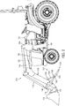
- FIGS. 1 and 2 illustrate a loader 100 that can be coupled to a utility vehicle, such as a tractor 102, and operated thereon.
- the loader 100 includes loader arms 104, which are couplable to the tractor 102 by a mast section 106 and a bracket 108 mounted on the tractor 102.
- a first actuator (e.g., a first hydraulic cylinder assembly) 110 is connected to the loader arm 104 and the mast section 106 to raise and lower the loader arm 104.
- An implement attachment bracket 112 which is equipped with an interchangeable implement (e.g., a bucket) 114 is arranged at a distal end of the loader arm 104.
- the implement attachment bracket 112 and thus also the implement 114, can be pivoted relative to the loader arm 104 by an actuation linkage 116, which can be controlled by a second actuator (e.g., a second hydraulic cylinder assembly) 118.
- actuation linkage 116 which can be controlled by a second actuator (e.g., a second hydraulic cylinder assembly) 118.
- Another linkage 120 is used for parallel guidance of the implement attachment bracket 112 and/or the implement 114 while the loader arm 104 is being raised and lowered.
- the loader 100 further includes a parking stand 122 disposed on the loader arm 104 and movable between a storage configuration ( FIG. 3 ) and a parking configuration ( FIG. 4 ).
- the parking stand 122 includes a lock brace 124 and a parking support 126.
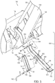
- the lock brace 124 is illustrated as a U-shaped channel member and includes a brace pivot end 128 pivotally coupled to the loader arm 104.
- the brace pivot end 128 is pivotally coupled to the loader arm 104 by a pivot pin 130 passing through brace pivot openings 132 defined in the lock brace 124.
- the pivot pin 130 is illustrated in FIG. 5 including two clips 134, which keep the pivot pin 130 laterally in place relative to the lock brace 124.
- the pivot pin 130 also passes through corresponding bracket openings 136 of the loader arm 104 to pivotally connect the lock brace 124 to the loader arm 104.
- the lock brace 124 further includes an attachment end 138 opposite the brace pivot end 128.
- the lock brace 124 includes two attachment holes 140 defined therein adjacent the attachment end 138 of the lock brace 124.
- the lock brace 124 is connectable to the parking support 126 by a retention pin 142 passing through the attachment holes 140 of the lock brace 124. The connection of the lock brace 124 to the parking support 126 will be discussed further below.
- the parking support 126 is illustrated as a generally U-shaped channel member and has a support pivot end 144 pivotally coupled to the loader arm 104.
- the support pivot end 144 is pivotally coupled to the loader arm 104 by a fastener (e.g., a bolt) 146 passing through support pivot openings 148 defined in the parking support 126 as shown in FIG. 5 .
- the fastener 146 also passes through a corresponding arm opening 150 of the loader arm 104 to pivotally connect the parking support 126 to the loader arm 104.
- the parking support 126 includes a ground engagement end 152 opposite the support pivot end 144.
- the ground engagement end 152 includes a foot 154.
- the parking support 126 further includes a storage opening 156 defined therein adjacent the ground engagement end 152.
- the loader arm 104 includes a corresponding storage aperture 158 defined therein.
- the parking support 126 is in the storage position as shown in FIG. 3 , the storage opening 156 of the parking support 126 aligns with the storage aperture 158 of the loader arm 104.
- a user may insert the retention pin 142 through both the storage opening 156 of the parking support 126 and the storage aperture 158 of the loader arm 104 to maintain the parking support 126 in the storage position during, for instance, operation of the tractor 102.
- the lock brace 124 is disconnected from the parking support 126 and nests in the U-shaped channel of the parking support 126.
- the parking support 126 also includes a wall, or a connection plate, 160 disposed between the support pivot end 144 and the ground engagement end 152.
- the connection plate 160 includes a plurality of connection regions 162 defined therein.
- the parking support 126 is originally manufactured with an obstruction 164 at each connection region 162.
- Each obstruction 164 is positioned to prevent a user from being able to removably couple the attachment end 138 of the lock brace 124 to the respective connection region 162 of the parking support 126.
- the illustrated embodiment includes obstructions 164 that are integral with the connection plate 160 of the parking support 126.
- each obstruction 164 is integrally formed as one piece with the connection plate 160.
- the obstructions 164 bridge each respective connection region 162 in a closed state.
- a continuous portion of the material between the obstruction 164 and the connection plate 160 is relatively narrow and, therefore, weak compared to the remainder of the connection plate 160.
- each obstruction 164 is partially surrounded by two diametrically opposed arcuate slots 166 defined in the connection plate 160, forming a stress concentration in the relatively narrow portion of material joining the obstruction 164 and the connection plate 160. In this manner, each obstruction 164 is removable from the parking support 126 by breaking the obstruction 164 away from the parking support 126 at the continuous portion of the material between the obstruction 164 and the connection plate 160.
- each obstruction 164 further includes a tool receiving portion in the form of a tool receiving hole 168 defined therein.
- a tool such as a screwdriver, 170 may be inserted in the tool receiving hole 168. The tool 170 is then used to twist the obstruction 164 relative to the parking support 126 until the continuities between the obstruction 164 and the parking support 126 break, thereby permanently detaching the obstruction 164 from the parking support 126.
- connection region 162 can be considered to be in an open state.
- the connection region 162 includes a through hole 172 defined in the connection plate 160.
- the attachment holes 140 of the lock brace 124 can then be aligned with the through hole 172 of the connection plate 160.
- the retention pin 142 is positioned in the attachment holes 140 and the through hole 172 to lock the parking stand 122 in the parking positon as shown in FIG. 4 .
- connection plate 160 includes two parallel connection plates 160 with connection regions 162 disposed on each connection plate 160.
- the connection regions 162 on one of the two parallel connection plates 160 of the parking support 126 are aligned with the connection regions 162 on the other of the two parallel connection plates 160 to facilitate insertion of the retention pin 142 in the through holes 172 when two corresponding connection regions 162 are in the open state.
- the lock brace 124 may also include a passage, or bushing, 174 to make insertion of the retention pin 142 through the attachment holes 140 and the through holes 172 easier for a user.
- the passage 174 may be welded to the lock brace 124 such that it defines a single attachment hole 140.
- connection regions 162 may include connection regions 162 that have a protrusion or a cavity instead of a through hole 172.
- the obstruction 164 may be a structure that at least partially surrounds the connection region 162.
- the obstruction 164 may be substantially similar to the removable wall section described above.
- the obstructions 164 may alternatively be a plug, pin, lock, or some other structure that is attached to the connection plate 160.
- the obstructions 164 are removable by either irreparably breaking the obstructions 164 or by specialized access with, for example, a key. In this manner, a user may not access a given connection region 162 by mistake.
- another illustrated embodiment includes connection regions 262 with respective obstructions 264 each partially surrounded by one arcuate slot 266 defined in the connection plate 260. Some embodiments further include the one arcuate slot 266 extending about a majority of the obstruction 264 such that the obstruction 264 is connected to the connection plate 260 by only a single relatively narrow portion of material. As illustrated in FIG. 8 , the single arcuate slot 266 is merged with the tool receiving portion in the form of a tool receiving hole 268. Stated another way, the tool receiving hole 268 is a continuous opening with the arcuate slot 266 in the illustrated embodiment in FIG. 8 . This embodiment may reduce the number of cutting steps in producing the parking support 226.
- the present disclosure also relates to a method of assembling a parking stand 122 with a loader arm 104 of a loader 100.
- the manufacturer attaches the parking support 126 to the loader arm 104 with a fastener 146 at a parking support pivot connection.
- the manufacturer also attaches the lock brace 124 to the loader arm 104 with a pivot pin 130 at a lock brace pivot connection.
- the parking support pivot connection is positioned closer to the implement attachment bracket 112, or the implement attachment end of the loader arm 104, than the lock brace pivot connection.
- connection region 162 is appropriate for the given loader 100 such that an end-user cannot overload the parking stand 122 when properly positioning the implement 114, the loader arms 104, and the tractor 102 to park the loader 100.
- the manufacturer may irreversibly break away the corresponding obstruction 164, thereby creating a through hole 172 in the connection plate 160.
- the proper connection region 162 allows the lock brace 124 to connect to the parking support 126 at an angle and position such that the ground engagement end 152 of the parking support 126 is even with or slightly elevated compared to a bottom surface of the implement 114 when the implement 114 is fully tilted back. In this manner, the implement 114 would experience all or a large majority of the loading force if the user accidentally lifts the front wheels of the tractor 102 off the ground by moving the loader arms 104 too far downward.
- an end-user cannot easily select and utilize an improper connection region 162 that would allow the parking stand 122 to experience an overloaded condition. If an end-user were to forcefully use an improper connection region 162, it would be evident to the manufacturer that the parking stand 122 has been improperly tampered with.
Landscapes
- Engineering & Computer Science (AREA)
- Mechanical Engineering (AREA)
- Mining & Mineral Resources (AREA)
- Civil Engineering (AREA)
- General Engineering & Computer Science (AREA)
- Structural Engineering (AREA)
- Shovels (AREA)
- Agricultural Machines (AREA)
Claims (15)
- Béquille de stationnement (122) pour raccordement à un bras de chargeur (104) d'un chargeur (100), la béquille de stationnement (122) comprenant :un support de stationnement (126) comprenantune extrémité de pivotement du support (144) configurée pour s'accoupler de manière pivotante au bras du chargeur (104),une extrémité d'engagement au sol (152) à l'opposé de l'extrémité de pivotement du support (144), etune paroi (160) disposée entre l'extrémité de pivotement du support (144) et l'extrémité d'engagement au sol (152), la paroi (160) comprenant une rangée de sections discrètes détachables (164) ; etune contrefiche de blocage (124) comprenantune extrémité de pivotement de la contrefiche (128) configurée pour s'accoupler de manière pivotante au bras du chargeur (104), etune extrémité de fixation (138) à l'opposé de l'extrémité de pivotement de la contrefiche (128), l'extrémité de fixation (138) comprenant un trou de fixation recevant une attache (140),
dans laquellela paroi (160) est configurée de telle sorte que l'enlèvement d'une section détachable respective (164) laisse un trou traversant (172) défini dans la paroi (160) du support de stationnement (126), etle trou de fixation (140) de la contrefiche de blocage (124) et le trou traversant (172) de la paroi (160) sont configurés pour s'aligner afin de recevoir une attache (142) à travers ceux-ci. - Béquille de stationnement (122) selon la revendication 1, dans laquellele support de stationnement (126) et la contrefiche de blocage (124) peuvent tous les deux être positionnés dans une configuration de stockage,le support de stationnement (126) est formé comme un membre à gorge généralement en forme de U, etla contrefiche de blocage (124) est emboîtée dans le support de stationnement dans la configuration de stockage.
- Béquille de stationnement (122) selon la revendication 1 ou 2, dans laquelle la contrefiche de blocage (124) est également un membre à gorge généralement en forme de U.
- Béquille de stationnement (122) selon la revendication 1, 2 ou 3, dans laquelle chacune des sections détachables (164) est configurée pour se détacher de la paroi (160) du support de stationnement (126).
- Béquille de stationnement (122) selon l'une quelconque des revendications précédentes, dans laquelle lors de l'enlèvement de la paroi (160) du support de stationnement (124), chacune des sections détachables (164) en est détachée en permanence.
- Béquille de stationnement (122) selon l'une quelconque des revendications précédentes, dans laquelle chacune des sections détachables (164) est formée intégralement comme une pièce avec la paroi (160).
- Béquille de stationnement (122) selon l'une quelconque des revendications précédentes, dans laquelle chacune des sections détachables (164) est entourée partiellement par une fente (166) définie dans la paroi (160).
- Béquille de stationnement (122) selon la revendication 7, dans laquelle la fente (166) est arquée.
- Béquille de stationnement (122) selon l'une quelconque des revendications précédentes, dans laquelle chacune des sections détachables (164) comprend une partie de réception d'outil (168).
- Béquille de stationnement (122) selon la revendication 9, dans laquelle la partie de réception d'outil (168) de chacune des sections détachables (164) comprend un trou de réception d'outil (168) défini dans la section détachable (164) respective.
- Chargeur (100) pour un tracteur (102), le chargeur (100) comprenant un bras de chargeur (104) et la béquille de stationnement (122) selon l'une quelconque des revendications 1 à 10 étant accouplée à celui-ci.
- Chargeur (100) selon la revendication 11, dans lequelle bras du chargeur (104) comprend une ouverture de stockage (158) définie dedans,le support de stationnement (126) comprend en outre une ouverture de stockage (156) définie dedans, etl'ouverture de stockage (156) du support de stationnement (126) s'aligne avec l'ouverture de stockage (158) du bras du chargeur (104) lorsque la béquille de stationnement (122) est dans une position de stockage.
- Chargeur (100) selon la revendication 12, comprenant en outreune goupille de retenue (142) occupant l'ouverture de stockage (156) du support de stationnement (126) et l'ouverture de stockage (158) du bras du chargeur (104) pour retenir la béquille de stationnement (122) dans la position de stockage, etdans lequelle trou de fixation (140) de la contrefiche de blocage (124) s'aligne avec le trou traversant (172) de la paroi (160) lorsque la béquille de stationnement (122) est dans la position de stationnement, etla goupille de retenue (142) occupe le trou de fixation (140) de la contrefiche de blocage (124) et le trou traversant (172) de la paroi (160) pour retenir la béquille de stationnement (122) dans la position de stationnement.
- Tracteur (102), le tracteur (102) comprenant le chargeur (100) selon la revendication 11 accouplé à celui-ci.
- Procédé d'assemblage de la béquille de stationnement (122) avec le bras de chargeur (104) du chargeur selon la revendication 11, le procédé comprenant :raccorder le support de stationnement (126) au bras du chargeur (104) à un raccordement de pivotement du support de stationnement ;raccorder la contrefiche de blocage (124) au bras du chargeur (104) à un raccordement de pivotement de la contrefiche de blocage ; etenlever l'une des sections détachables (164) de la paroi (160), créant ainsi le trou traversant (172) défini dans la paroi du support de stationnement (126).
Applications Claiming Priority (1)
| Application Number | Priority Date | Filing Date | Title |
|---|---|---|---|
| US16/398,537 US20200347568A1 (en) | 2019-04-30 | 2019-04-30 | Loader parking stand |
Publications (2)
| Publication Number | Publication Date |
|---|---|
| EP3733979A1 EP3733979A1 (fr) | 2020-11-04 |
| EP3733979B1 true EP3733979B1 (fr) | 2021-11-10 |
Family
ID=70617030
Family Applications (1)
| Application Number | Title | Priority Date | Filing Date |
|---|---|---|---|
| EP20173557.8A Active EP3733979B1 (fr) | 2019-04-30 | 2020-05-07 | Support de chargeur |
Country Status (3)
| Country | Link |
|---|---|
| US (1) | US20200347568A1 (fr) |
| EP (1) | EP3733979B1 (fr) |
| CA (1) | CA3079818A1 (fr) |
Families Citing this family (1)
| Publication number | Priority date | Publication date | Assignee | Title |
|---|---|---|---|---|
| US11952743B2 (en) | 2021-10-15 | 2024-04-09 | Deere & Company | Loader with moving apparatus |
Family Cites Families (4)
| Publication number | Priority date | Publication date | Assignee | Title |
|---|---|---|---|---|
| DE9108865U1 (de) * | 1991-07-18 | 1991-09-19 | Xaver Fendt & Co, 8952 Marktoberdorf | Längenverstellbare Abstellstütze an einem Frontlader |
| EP2092126A1 (fr) * | 2006-12-13 | 2009-08-26 | Challenge Implements Holdings Pty Limited | Support de stationnement |
| FR2968363B1 (fr) * | 2010-12-03 | 2014-12-05 | Snecma | Rotor de turbomachine avec une cale anti-usure entre un disque et un anneau |
| US9650754B2 (en) * | 2015-05-28 | 2017-05-16 | Deere & Company | Automatic position locking mechanism for loader assembly parking stands |
-
2019
- 2019-04-30 US US16/398,537 patent/US20200347568A1/en not_active Abandoned
-
2020
- 2020-04-29 CA CA3079818A patent/CA3079818A1/fr active Pending
- 2020-05-07 EP EP20173557.8A patent/EP3733979B1/fr active Active
Also Published As
| Publication number | Publication date |
|---|---|
| EP3733979A1 (fr) | 2020-11-04 |
| US20200347568A1 (en) | 2020-11-05 |
| CA3079818A1 (fr) | 2020-10-30 |
Similar Documents
| Publication | Publication Date | Title |
|---|---|---|
| US9051716B2 (en) | Zero offset loader coupling system and components | |
| EP0405813B1 (fr) | Dispositif d'attelage d'un outil de travail | |
| EP1254287B1 (fr) | Coupleur universel pour bennes d'excavation | |
| US5110254A (en) | Quick-release coupling for earthworking machines | |
| US5529419A (en) | High visibility coupler for front end loader | |
| US6508616B2 (en) | Bucket fastener for a hydraulic shovel | |
| US20040067126A1 (en) | Coupling assembly | |
| US8500386B2 (en) | Latching system for automatically securing front-mounted loader mast to tractor mounting frame | |
| GB2332417A (en) | Safety latches for an attachment device | |
| US20020127090A1 (en) | Power latch adapter for quick change attachment coupler | |
| US6709224B2 (en) | Implement coupling assembly | |
| GB2492850A (en) | Hitch coupler | |
| AU2007332136B2 (en) | Parking stand | |
| US7225566B1 (en) | Hybrid male coupler portion for a front-end loader | |
| CN101379248B (zh) | 用于附件安装装置的控制回路 | |
| EP3733979A1 (fr) | Support de chargeur | |
| EP2310578B1 (fr) | Dispositif de verrouillage destiné à fixer une pelle rétrocaveuse à un bras de levage porteur | |
| US7073972B1 (en) | Conversion plate with schur-lock pin mechanism | |
| US10233612B2 (en) | Tractor attachment and tractor attachment kit | |
| US7086821B1 (en) | Quick attachment arrangement for end loader | |
| US11952738B2 (en) | Attachment coupler | |
| US9121162B1 (en) | Motor coupler with multiple pick up locations | |
| CA3131118C (fr) | Ensemble de raccordement pour éléments accessoires électriques | |
| CN117419088A (zh) | 快速联接器和具有这种快速联接器的快速联接系统 | |
| CN114809154A (zh) | 一种快速连接器 |
Legal Events
| Date | Code | Title | Description |
|---|---|---|---|
| PUAI | Public reference made under article 153(3) epc to a published international application that has entered the european phase |
Free format text: ORIGINAL CODE: 0009012 |
|
| STAA | Information on the status of an ep patent application or granted ep patent |
Free format text: STATUS: THE APPLICATION HAS BEEN PUBLISHED |
|
| AK | Designated contracting states |
Kind code of ref document: A1 Designated state(s): AL AT BE BG CH CY CZ DE DK EE ES FI FR GB GR HR HU IE IS IT LI LT LU LV MC MK MT NL NO PL PT RO RS SE SI SK SM TR |
|
| AX | Request for extension of the european patent |
Extension state: BA ME |
|
| STAA | Information on the status of an ep patent application or granted ep patent |
Free format text: STATUS: REQUEST FOR EXAMINATION WAS MADE |
|
| 17P | Request for examination filed |
Effective date: 20210430 |
|
| RBV | Designated contracting states (corrected) |
Designated state(s): AL AT BE BG CH CY CZ DE DK EE ES FI FR GB GR HR HU IE IS IT LI LT LU LV MC MK MT NL NO PL PT RO RS SE SI SK SM TR |
|
| GRAP | Despatch of communication of intention to grant a patent |
Free format text: ORIGINAL CODE: EPIDOSNIGR1 |
|
| STAA | Information on the status of an ep patent application or granted ep patent |
Free format text: STATUS: GRANT OF PATENT IS INTENDED |
|
| RIC1 | Information provided on ipc code assigned before grant |
Ipc: E02F 3/627 20060101AFI20210629BHEP |
|
| INTG | Intention to grant announced |
Effective date: 20210721 |
|
| GRAS | Grant fee paid |
Free format text: ORIGINAL CODE: EPIDOSNIGR3 |
|
| GRAA | (expected) grant |
Free format text: ORIGINAL CODE: 0009210 |
|
| STAA | Information on the status of an ep patent application or granted ep patent |
Free format text: STATUS: THE PATENT HAS BEEN GRANTED |
|
| AK | Designated contracting states |
Kind code of ref document: B1 Designated state(s): AL AT BE BG CH CY CZ DE DK EE ES FI FR GB GR HR HU IE IS IT LI LT LU LV MC MK MT NL NO PL PT RO RS SE SI SK SM TR |
|
| REG | Reference to a national code |
Ref country code: GB Ref legal event code: FG4D |
|
| REG | Reference to a national code |
Ref country code: AT Ref legal event code: REF Ref document number: 1446214 Country of ref document: AT Kind code of ref document: T Effective date: 20211115 Ref country code: CH Ref legal event code: EP |
|
| REG | Reference to a national code |
Ref country code: DE Ref legal event code: R096 Ref document number: 602020000959 Country of ref document: DE |
|
| REG | Reference to a national code |
Ref country code: IE Ref legal event code: FG4D |
|
| REG | Reference to a national code |
Ref country code: LT Ref legal event code: MG9D |
|
| REG | Reference to a national code |
Ref country code: NL Ref legal event code: MP Effective date: 20211110 |
|
| REG | Reference to a national code |
Ref country code: AT Ref legal event code: MK05 Ref document number: 1446214 Country of ref document: AT Kind code of ref document: T Effective date: 20211110 |
|
| PG25 | Lapsed in a contracting state [announced via postgrant information from national office to epo] |
Ref country code: RS Free format text: LAPSE BECAUSE OF FAILURE TO SUBMIT A TRANSLATION OF THE DESCRIPTION OR TO PAY THE FEE WITHIN THE PRESCRIBED TIME-LIMIT Effective date: 20211110 Ref country code: LT Free format text: LAPSE BECAUSE OF FAILURE TO SUBMIT A TRANSLATION OF THE DESCRIPTION OR TO PAY THE FEE WITHIN THE PRESCRIBED TIME-LIMIT Effective date: 20211110 Ref country code: FI Free format text: LAPSE BECAUSE OF FAILURE TO SUBMIT A TRANSLATION OF THE DESCRIPTION OR TO PAY THE FEE WITHIN THE PRESCRIBED TIME-LIMIT Effective date: 20211110 Ref country code: BG Free format text: LAPSE BECAUSE OF FAILURE TO SUBMIT A TRANSLATION OF THE DESCRIPTION OR TO PAY THE FEE WITHIN THE PRESCRIBED TIME-LIMIT Effective date: 20220210 Ref country code: AT Free format text: LAPSE BECAUSE OF FAILURE TO SUBMIT A TRANSLATION OF THE DESCRIPTION OR TO PAY THE FEE WITHIN THE PRESCRIBED TIME-LIMIT Effective date: 20211110 |
|
| PG25 | Lapsed in a contracting state [announced via postgrant information from national office to epo] |
Ref country code: IS Free format text: LAPSE BECAUSE OF FAILURE TO SUBMIT A TRANSLATION OF THE DESCRIPTION OR TO PAY THE FEE WITHIN THE PRESCRIBED TIME-LIMIT Effective date: 20220310 Ref country code: SE Free format text: LAPSE BECAUSE OF FAILURE TO SUBMIT A TRANSLATION OF THE DESCRIPTION OR TO PAY THE FEE WITHIN THE PRESCRIBED TIME-LIMIT Effective date: 20211110 Ref country code: PT Free format text: LAPSE BECAUSE OF FAILURE TO SUBMIT A TRANSLATION OF THE DESCRIPTION OR TO PAY THE FEE WITHIN THE PRESCRIBED TIME-LIMIT Effective date: 20220310 Ref country code: PL Free format text: LAPSE BECAUSE OF FAILURE TO SUBMIT A TRANSLATION OF THE DESCRIPTION OR TO PAY THE FEE WITHIN THE PRESCRIBED TIME-LIMIT Effective date: 20211110 Ref country code: NO Free format text: LAPSE BECAUSE OF FAILURE TO SUBMIT A TRANSLATION OF THE DESCRIPTION OR TO PAY THE FEE WITHIN THE PRESCRIBED TIME-LIMIT Effective date: 20220210 Ref country code: NL Free format text: LAPSE BECAUSE OF FAILURE TO SUBMIT A TRANSLATION OF THE DESCRIPTION OR TO PAY THE FEE WITHIN THE PRESCRIBED TIME-LIMIT Effective date: 20211110 Ref country code: LV Free format text: LAPSE BECAUSE OF FAILURE TO SUBMIT A TRANSLATION OF THE DESCRIPTION OR TO PAY THE FEE WITHIN THE PRESCRIBED TIME-LIMIT Effective date: 20211110 Ref country code: HR Free format text: LAPSE BECAUSE OF FAILURE TO SUBMIT A TRANSLATION OF THE DESCRIPTION OR TO PAY THE FEE WITHIN THE PRESCRIBED TIME-LIMIT Effective date: 20211110 Ref country code: GR Free format text: LAPSE BECAUSE OF FAILURE TO SUBMIT A TRANSLATION OF THE DESCRIPTION OR TO PAY THE FEE WITHIN THE PRESCRIBED TIME-LIMIT Effective date: 20220211 |
|
| PG25 | Lapsed in a contracting state [announced via postgrant information from national office to epo] |
Ref country code: SM Free format text: LAPSE BECAUSE OF FAILURE TO SUBMIT A TRANSLATION OF THE DESCRIPTION OR TO PAY THE FEE WITHIN THE PRESCRIBED TIME-LIMIT Effective date: 20211110 Ref country code: SK Free format text: LAPSE BECAUSE OF FAILURE TO SUBMIT A TRANSLATION OF THE DESCRIPTION OR TO PAY THE FEE WITHIN THE PRESCRIBED TIME-LIMIT Effective date: 20211110 Ref country code: RO Free format text: LAPSE BECAUSE OF FAILURE TO SUBMIT A TRANSLATION OF THE DESCRIPTION OR TO PAY THE FEE WITHIN THE PRESCRIBED TIME-LIMIT Effective date: 20211110 Ref country code: ES Free format text: LAPSE BECAUSE OF FAILURE TO SUBMIT A TRANSLATION OF THE DESCRIPTION OR TO PAY THE FEE WITHIN THE PRESCRIBED TIME-LIMIT Effective date: 20211110 Ref country code: EE Free format text: LAPSE BECAUSE OF FAILURE TO SUBMIT A TRANSLATION OF THE DESCRIPTION OR TO PAY THE FEE WITHIN THE PRESCRIBED TIME-LIMIT Effective date: 20211110 Ref country code: DK Free format text: LAPSE BECAUSE OF FAILURE TO SUBMIT A TRANSLATION OF THE DESCRIPTION OR TO PAY THE FEE WITHIN THE PRESCRIBED TIME-LIMIT Effective date: 20211110 Ref country code: CZ Free format text: LAPSE BECAUSE OF FAILURE TO SUBMIT A TRANSLATION OF THE DESCRIPTION OR TO PAY THE FEE WITHIN THE PRESCRIBED TIME-LIMIT Effective date: 20211110 |
|
| REG | Reference to a national code |
Ref country code: DE Ref legal event code: R097 Ref document number: 602020000959 Country of ref document: DE |
|
| PLBE | No opposition filed within time limit |
Free format text: ORIGINAL CODE: 0009261 |
|
| STAA | Information on the status of an ep patent application or granted ep patent |
Free format text: STATUS: NO OPPOSITION FILED WITHIN TIME LIMIT |
|
| 26N | No opposition filed |
Effective date: 20220811 |
|
| PG25 | Lapsed in a contracting state [announced via postgrant information from national office to epo] |
Ref country code: AL Free format text: LAPSE BECAUSE OF FAILURE TO SUBMIT A TRANSLATION OF THE DESCRIPTION OR TO PAY THE FEE WITHIN THE PRESCRIBED TIME-LIMIT Effective date: 20211110 |
|
| PG25 | Lapsed in a contracting state [announced via postgrant information from national office to epo] |
Ref country code: SI Free format text: LAPSE BECAUSE OF FAILURE TO SUBMIT A TRANSLATION OF THE DESCRIPTION OR TO PAY THE FEE WITHIN THE PRESCRIBED TIME-LIMIT Effective date: 20211110 |
|
| REG | Reference to a national code |
Ref country code: BE Ref legal event code: MM Effective date: 20220531 |
|
| PG25 | Lapsed in a contracting state [announced via postgrant information from national office to epo] |
Ref country code: MC Free format text: LAPSE BECAUSE OF FAILURE TO SUBMIT A TRANSLATION OF THE DESCRIPTION OR TO PAY THE FEE WITHIN THE PRESCRIBED TIME-LIMIT Effective date: 20211110 Ref country code: LU Free format text: LAPSE BECAUSE OF NON-PAYMENT OF DUE FEES Effective date: 20220507 |
|
| PG25 | Lapsed in a contracting state [announced via postgrant information from national office to epo] |
Ref country code: IE Free format text: LAPSE BECAUSE OF NON-PAYMENT OF DUE FEES Effective date: 20220507 |
|
| PG25 | Lapsed in a contracting state [announced via postgrant information from national office to epo] |
Ref country code: IT Free format text: LAPSE BECAUSE OF FAILURE TO SUBMIT A TRANSLATION OF THE DESCRIPTION OR TO PAY THE FEE WITHIN THE PRESCRIBED TIME-LIMIT Effective date: 20211110 Ref country code: BE Free format text: LAPSE BECAUSE OF NON-PAYMENT OF DUE FEES Effective date: 20220531 |
|
| REG | Reference to a national code |
Ref country code: CH Ref legal event code: PL |
|
| PG25 | Lapsed in a contracting state [announced via postgrant information from national office to epo] |
Ref country code: LI Free format text: LAPSE BECAUSE OF NON-PAYMENT OF DUE FEES Effective date: 20230531 Ref country code: CH Free format text: LAPSE BECAUSE OF NON-PAYMENT OF DUE FEES Effective date: 20230531 |
|
| PG25 | Lapsed in a contracting state [announced via postgrant information from national office to epo] |
Ref country code: MK Free format text: LAPSE BECAUSE OF FAILURE TO SUBMIT A TRANSLATION OF THE DESCRIPTION OR TO PAY THE FEE WITHIN THE PRESCRIBED TIME-LIMIT Effective date: 20211110 Ref country code: CY Free format text: LAPSE BECAUSE OF FAILURE TO SUBMIT A TRANSLATION OF THE DESCRIPTION OR TO PAY THE FEE WITHIN THE PRESCRIBED TIME-LIMIT Effective date: 20211110 |
|
| PG25 | Lapsed in a contracting state [announced via postgrant information from national office to epo] |
Ref country code: HU Free format text: LAPSE BECAUSE OF FAILURE TO SUBMIT A TRANSLATION OF THE DESCRIPTION OR TO PAY THE FEE WITHIN THE PRESCRIBED TIME-LIMIT; INVALID AB INITIO Effective date: 20200507 |
|
| PG25 | Lapsed in a contracting state [announced via postgrant information from national office to epo] |
Ref country code: TR Free format text: LAPSE BECAUSE OF FAILURE TO SUBMIT A TRANSLATION OF THE DESCRIPTION OR TO PAY THE FEE WITHIN THE PRESCRIBED TIME-LIMIT Effective date: 20211110 |
|
| PG25 | Lapsed in a contracting state [announced via postgrant information from national office to epo] |
Ref country code: MT Free format text: LAPSE BECAUSE OF FAILURE TO SUBMIT A TRANSLATION OF THE DESCRIPTION OR TO PAY THE FEE WITHIN THE PRESCRIBED TIME-LIMIT Effective date: 20211110 |
|
| PGFP | Annual fee paid to national office [announced via postgrant information from national office to epo] |
Ref country code: DE Payment date: 20250423 Year of fee payment: 6 |
|
| PGFP | Annual fee paid to national office [announced via postgrant information from national office to epo] |
Ref country code: GB Payment date: 20250527 Year of fee payment: 6 |
|
| PGFP | Annual fee paid to national office [announced via postgrant information from national office to epo] |
Ref country code: FR Payment date: 20250526 Year of fee payment: 6 |