EP3734065B1 - Aktuatoranordnung - Google Patents
Aktuatoranordnung Download PDFInfo
- Publication number
- EP3734065B1 EP3734065B1 EP19171912.9A EP19171912A EP3734065B1 EP 3734065 B1 EP3734065 B1 EP 3734065B1 EP 19171912 A EP19171912 A EP 19171912A EP 3734065 B1 EP3734065 B1 EP 3734065B1
- Authority
- EP
- European Patent Office
- Prior art keywords
- actuator
- substrate
- circuit path
- hole
- fixing member
- Prior art date
- Legal status (The legal status is an assumption and is not a legal conclusion. Google has not performed a legal analysis and makes no representation as to the accuracy of the status listed.)
- Active
Links
Images





Classifications
-
- F—MECHANICAL ENGINEERING; LIGHTING; HEATING; WEAPONS; BLASTING
- F03—MACHINES OR ENGINES FOR LIQUIDS; WIND, SPRING, OR WEIGHT MOTORS; PRODUCING MECHANICAL POWER OR A REACTIVE PROPULSIVE THRUST, NOT OTHERWISE PROVIDED FOR
- F03G—SPRING, WEIGHT, INERTIA OR LIKE MOTORS; MECHANICAL-POWER PRODUCING DEVICES OR MECHANISMS, NOT OTHERWISE PROVIDED FOR OR USING ENERGY SOURCES NOT OTHERWISE PROVIDED FOR
- F03G7/00—Mechanical-power-producing mechanisms, not otherwise provided for or using energy sources not otherwise provided for
- F03G7/06—Mechanical-power-producing mechanisms, not otherwise provided for or using energy sources not otherwise provided for using expansion or contraction of bodies due to heating, cooling, moistening, drying or the like
- F03G7/061—Mechanical-power-producing mechanisms, not otherwise provided for or using energy sources not otherwise provided for using expansion or contraction of bodies due to heating, cooling, moistening, drying or the like characterised by the actuating element
- F03G7/0614—Mechanical-power-producing mechanisms, not otherwise provided for or using energy sources not otherwise provided for using expansion or contraction of bodies due to heating, cooling, moistening, drying or the like characterised by the actuating element using shape memory elements
-
- F—MECHANICAL ENGINEERING; LIGHTING; HEATING; WEAPONS; BLASTING
- F03—MACHINES OR ENGINES FOR LIQUIDS; WIND, SPRING, OR WEIGHT MOTORS; PRODUCING MECHANICAL POWER OR A REACTIVE PROPULSIVE THRUST, NOT OTHERWISE PROVIDED FOR
- F03G—SPRING, WEIGHT, INERTIA OR LIKE MOTORS; MECHANICAL-POWER PRODUCING DEVICES OR MECHANISMS, NOT OTHERWISE PROVIDED FOR OR USING ENERGY SOURCES NOT OTHERWISE PROVIDED FOR
- F03G7/00—Mechanical-power-producing mechanisms, not otherwise provided for or using energy sources not otherwise provided for
- F03G7/06—Mechanical-power-producing mechanisms, not otherwise provided for or using energy sources not otherwise provided for using expansion or contraction of bodies due to heating, cooling, moistening, drying or the like
- F03G7/061—Mechanical-power-producing mechanisms, not otherwise provided for or using energy sources not otherwise provided for using expansion or contraction of bodies due to heating, cooling, moistening, drying or the like characterised by the actuating element
- F03G7/0616—Mechanical-power-producing mechanisms, not otherwise provided for or using energy sources not otherwise provided for using expansion or contraction of bodies due to heating, cooling, moistening, drying or the like characterised by the actuating element characterised by the material or the manufacturing process, e.g. the assembly
Definitions
- the present invention relates to an actuator assembly.
- the present invention further relates to a method and an apparatus for manufacturing an actuator assembly.
- the present invention further relates to a valve comprising an actuator assembly.
- actuators made of a shape memory alloy SMA
- SMA shape memory alloy
- the technical application of this type of actuators requires a mechanical connection of the actuator to a casing which provides resistance to the occurring forces. If the actuator is formed as a SMA wire, the mechanical connection is usually realized by means of crimp joining. However, crimp joining is rather unsuitable for actuators made of a shape memory alloy having a planar geometry.
- DE 31 41 216 A1 describes a fixation process of planar actuator elements made of a shape memory alloy within a tube by means of rivets.
- the rivets exclusively provide a mechanical connection to the tube.
- the shape memory effect is activated by means of the temperature of a gas flowing through the tube.
- DE 197 54 747 A1 discloses a device for being implanted into hollow space of human body in particular into gullet.
- the device consists of a mesh with polygonal cells and is made of synthetic material or a thin metal wire.
- the areas where the threads meet are fixed with tubular rivets. First the threads are joined in order to form a specific shape like the inside of the gullet, wound around the cylindrical shaft of the rivet and then permanently fixed.
- the individual cells of the mesh should be ideally wider at both ends of the device and narrow in the middle to give maximum support.
- DE 10 2016 219 245 A1 discloses a coupling device which is rotatably supportable about an axis of rotation, wherein the coupling device comprises at least one lamellae carrier and a component, wherein the lamellae carrier is fixed to the component in a torque proof and axial proof manner, wherein the plate carrier comprises a first material and the component comprises a second material, wherein the first material is different from the second material.
- the fixation is realized by means of a rivet which fixation also may use a biasing means made of a shape memory material.
- US2017/097104 A1 discloses an actuator assembly comprising a substrate having a circuit path and an actuator element made of a shape memory alloy, wherein the substrate and the circuit path have a through hole where a fixing member extends.
- the present invention differs from this known actuator in that the actuator element comprises a through hole, and in that the fixing member permanently fixes the actuator element to the substrate by extending through the hole.
- the terms “have”, “comprise” or “include” or any arbitrary grammatical variations thereof are used in a non-exclusive way. Thus, these terms may both refer to a situation in which, besides the feature introduced by these terms, no further features are present in the entity described in this context and to a situation in which one or more further features are present.
- the expressions “A has B”, “A comprises B” and “A includes B” may both refer to a situation in which, besides B, no other element is present in A (i.e. a situation in which A solely and exclusively consists of B) and to a situation in which, besides B, one or more further elements are present in entity A, such as element C, elements C and D or even further elements.
- the terms "at least one”, “one or more” or similar expressions indicating that a feature or element may be present once or more than once typically will be used only once when introducing the respective feature or element.
- the expressions “at least one” or “one or more” will not be repeated, non-withstanding the fact that the respective feature or element may be present once or more than once.
- shape memory material is a broad term and is to be given its ordinary and customary meaning to a person of ordinary skill in the art and is not to be limited to a special or customized meaning.
- the term specifically may refer, without limitation, to any material that has the ability to return from a deformed state (temporary shape) to its original (permanent) shape induced by an external stimulus (trigger), such as temperature change.
- shape memory material may be shape-memory polymers (SMPs) or shape-memory alloys (SMAs).
- SMPs shape-memory polymers
- SMAs shape-memory alloys
- a shape-memory alloy is an alloy that can be deformed when cold but returns to its pre-deformed (“remembered") shape when heated.
- Shape-memory polymers differ from shape memory alloys by their glass transition or melting transition from a hard to a soft phase which is responsible for the shape-memory effect. In shape-memory alloys martensitic/austenitic transitions are responsible for the shape-memory effect.
- substrate as used herein is a broad term and is to be given its ordinary and customary meaning to a person of ordinary skill in the art and is not to be limited to a special or customized meaning.
- the term specifically may refer, without limitation, to any device suitable to support or carry an actuator and circuit paths.
- a substrate may be a common circuit board made of a rigid material, a circuit board made of a flexible material such as Kapton or a three-dimensional casing having circuit paths applied thereto.
- fixation not releasable or not releasable without destruction of the connection members.
- a permanent fixation is preferably a positive fit or positive locking.
- a non limiting example for a permanent fixation is a fixation of two connection members by means of a rivet.
- actuator as used herein is a broad term and is to be given its ordinary and customary meaning to a person of ordinary skill in the art and is not to be limited to a special or customized meaning.
- the term specifically may refer, without limitation, to an arbitrary element which is configured to move or control a mechanism or a system.
- the actuator may be operated by a source of energy, typically electric current or heat.
- circuit path is a broad term and is to be given its ordinary and customary meaning to a person of ordinary skill in the art and is not to be limited to a special or customized meaning.
- the term specifically may refer, without limitation, to a trace made of an electrically conductive material such as copper which is configured to provide an electrical connection of at least two constructional members.
- first, second, etc. as used herein are merely used to distinguish between different constructional members or features but do not define a certain order of importance.
- actuating section is a broad term and is to be given its ordinary and customary meaning to a person of ordinary skill in the art and is not to be limited to a special or customized meaning.
- the term specifically may refer, without limitation, to that part of the actuator that connects the ends thereof and that is deformed in the cold state and performs the actuation movement by restoring its memory shape when heated above the temperature Af. It may have a variety of shapes including a straight bridge, several parallel straight bridges, several non-parallel, intersecting straight bridges, meandering structures, bows, spiral arms, "Kirigami"-like structures formed by introducing a number of cuts into the actuator plane.
- the actuating section should preferably be stressed as uniformly as possible when deforming the actuator in order to omit mechanical failure.
- the actuating section should allow heating by applying a heating current between the first end and second end of the actuator. In this case, the current density should be as uniform as possible in order to achieve uniform heating of the entire actuating section.
- biasing as used herein is a broad term and is to be given its ordinary and customary meaning to a person of ordinary skill in the art and is not to be limited to a special or customized meaning.
- the term specifically may refer, without limitation, to a pre-strained state of shape. With other words, a biased structure or element is deflected with respect to the memory shape of a shape memory material.
- an actuator assembly which comprises at least one substrate having at least a first circuit path and/or a second circuit path mounted on at least one side of the substrate, at least one actuator made at least partially of a shape memory material, wherein the actuator comprises at least a first end and a second end, and at least one fixing member.
- the first end comprises a first actuator through hole
- the first circuit path comprises a first support surface defining a first circuit path through hole.
- the substrate comprises a first substrate through hole. The first actuator through hole, the first circuit path through hole and the first substrate through hole overlap one another.
- the fixing member extends through the first actuator through hole, the first circuit path through hole and the first substrate through hole such that the actuator is permanently fixed to the substrate and the first circuit path at least at the first end by means of the fixing member.
- these circuit paths may be used to supply the actuator with electrical power and to remove heat therefrom.
- the actuator is made of a shape memory material, the actuator can exist in two different phases having different shapes and structures, respectively. As these phases have different geometries, shapes or structures, the actuator is allowed to move to a certain extension. This movement may be used to operate a further constructional member such as switching between at least two different positions or gradual or linear movement.
- a shape memory actuator may be used for implementation of an actuator assembly that may be operated by open-loop or closed-loop control, e.g. a proportional valve (e.g. for dosing), a mixing valve or an optical aperture.
- a proportional valve e.g. for dosing
- a mixing valve e.g. for dosing
- an optical aperture e.g. a proportional valve (e.g. for dosing), a mixing valve or an optical aperture.
- the overlapping of the first actuator through hole, the first circuit path through hole and the first substrate through hole is not necessarily limited to this given order but may be realized in any order.
- the actuator and the first circuit path may be located on different sides of the substrate.
- the second end may comprise a second actuator through hole.
- the second circuit path may comprise a second support surface defining a second circuit path through hole.
- the substrate may comprise a second substrate through hole.
- the second actuator through hole, the second circuit path through hole and the second substrate through hole may overlap one another.
- the fixing member may extend through the second actuator through hole, the second circuit path through hole and the second substrate through hole such that the actuator is permanently fixed to the substrate and the second circuit path at the second end by means of the fixing member.
- a further or additional fixing member may be inserted into these holes so as to extend therethrough.
- a further or second mechanical connection of the substrate, the second circuit path and the actuator may be realized which also allows to supply the actuator with electrical power such as a heating current and/or to remove heat from the actuator.
- the actuator may be fixed to the substrate and the two different circuit paths at two different locations.
- the fixing member may be a rivet, wherein the rivet is preferably made from an electrically conductive material and/or has an electrically conductive surface coating.
- the rivet is a hollow rivet.
- an electrical connection of the actuator to the first and/or second circuit path may be realized by means of the rivet. This allows to supply the actuator with a heating current.
- the rivet may be made of an electrically conductive material, its manufacturing may be easier or more cost effective than the provision of an electrically conductive surface coating.
- the rivet may be made of a broad range of materials such as a shape memory alloy, a thermoplastic material or any other material.
- the (electrically conductive) surface finish of the fixing member is non-corrosive.
- the actuator is preferably electrically connected to the first circuit path and/or the second circuit path by means of the fixing member.
- the electrical connection of the actuator to the first circuit path and/or the second circuit path may be realized in that the actuator is pressed onto the first circuit path and/or the second circuit path.
- the electrical connection of the actuator to the first circuit path and/or the second circuit path may be realized in that the fixing member is made of an electrically conductive material or comprises an electrically conductive material such as a coating which allows to supply the actuator with electrical power even if not in direct contact to the first circuit path and/or the second circuit path such as across the substrate.
- the first circuit path and the second circuit path on the one hand side and the actuator on the other hand side may be located on the same side of the substrate.
- the manufacturing of the actuator assembly may be simplified and the fixing member does not necessarily have to be made of or comprise an electrically conductive material.
- the first circuit path and the second circuit path on the one hand side and the actuator on the other hand side may be located on opposing sides of the substrate.
- the fixing member has to be made of or comprise an electrically conductive material.
- the actuator assembly may further comprise at least two actuators made of a shape memory material, wherein the two actuators are on the same side of the substrate.
- actuator assembly may comprise two or more actuators such as three, four etc. actuators which arrangement allows to provide movements in several directions and/or actuation with several dependent or independent degrees of freedom.
- the at least two actuators may be connected to one another by means of an intermediate member.
- the connection of the two or more actuators by means of the intermediate member may be realized after the manufacturing of the actuators.
- the actuators and the intermediate member may be integrally or monolithically formed such as by being cut off from a shape memory material foil.
- Two or more actuators may be connected to one another. For example, three or four actuators are arranged in a star shaped manner so as to realize a two-dimensional movement. If the intermediate member comprises a slot or opening, the actuator assembly may be used in association with an optical aperture or a gate valve.
- the at least two actuators may be biased in opposite directions. Thus, a linear actuation movement is allowed. If the two or more actuators are not biased against one another, the actuators were in their shape memory state and the application of a heating current to one of the actuators would not result in a modification or variation of the shape and thereby in an actuation or movement.
- the actuator assembly may further comprise at least two actuators made of a shape memory material, wherein the two actuators are on opposing sides of the substrate. This decreases the total space for the arrangement of two or more actuators.
- the two actuators on opposing sides of the substrate may be biased with respect to each other.
- a movement orthogonal to the substrate plane (out-of-plane) can be realized.
- the at least two actuators may be permanently fixed to the substrate and at least one first circuit path at least at the first ends thereof by means of a single fixing member. This decreases the total space for the arrangement of two or more actuators as a common circuit path such as common ground may be used for the actuators.
- the actuator assembly may further comprise two substrates, wherein at least one of the substrates has at least a first circuit path and a second circuit path mounted thereon, wherein the actuator is located between the two substrates.
- the circuit paths do not necessarily have to be provided on all substrates. Rather, for each end to be connected at least one circuit path must be provided on at least one substrate.
- the actuator assembly may further comprise a casing, wherein the actuator is permanently fixed to the substrate, the first circuit path and the casing at least at the first end by means of the fixing member. Thereby, the actuator may be at least partially enclosed so as to be protected from the environment.
- the substrate may be formed as a casing.
- the actuator may be directly fixed to a casing by means of the fixing member.
- the substrate may be a circuit board member.
- the actuator may be fixed to well established electronic components which allows to decrease the costs for its manufacturing.
- the electronic components may include microcontrollers and transistors for controlling the power supply of the actuator, energy storages such as batteries or supercapacitors, electrical connectors or plugs, sensors for supervising the ambient conditions and/or actuator condition such as temperature, fluid flow, position (e.g. hall sensors), electrical resistance, light intensity.
- the substrate may be flexible.
- a flexible substrate may fulfil the function of a connection cable such that a further cable may be omitted.
- the substrate may be a casing comprising at least one circuit path, which is preferably formed by selective surface metallization.
- the actuator assembly may further comprise an elastic resetting member configured to reset the actuator into its original (shape memory) position.
- an elastic resetting member configured to reset the actuator into its original deformed shape when power supply is stopped, as the shape memory effect only occurs when the actuator is heated above a material-specific critical temperature Af.
- the elastic resetting member may be permanently fixed to the substrate by means of at least one fixing member such as by means of at least one rivet.
- the actuator and the resetting member may be fixed to the substrate by means of the same tool or apparatus and/or within the same process step.
- the actuator assembly may further comprise a lever, wherein the actuator is configured to move, particularly pivot, the lever.
- the actuator assembly may be used to induce a pivotal or linear movement which is particularly usable in model building.
- the actuator may be formed substantially planar at least at the first and/or second end.
- the thickness of the actuator assembly may be reduced.
- the whole actuator may be planar.
- the actuator may comprise a thickness in a range of 10 ⁇ m to 200 ⁇ m, which may be present at least at the first and/or second end.
- Such at least partially planar actuators may be realized as foil, film, plate, sheet, band, flat wire; conventional wire with flattened ends.
- Such at least partially planar actuators may be manufactured by means of physical vapor deposition such as sputter deposition, cold rolling, cold drawing, mechanical thinning, grinding, polishing, melt spinning or the like.
- the respective shape may be defined by means of photolithography, wire cutting, laser cutting, water jet cutting or stamping.
- the first end and the second end of the actuator may be connected to one another by means of at least one actuating section.
- the actuating section allows to provide a structure that is deformed when cold and remember its shape when being heated.
- Such an actuating section may be similar to a bar, berth or bridge connecting the ends.
- the at least one actuating section may be formed straight or curved, particularly meandering, or Kirigami-like, i.e. formed by introducing a variety of straight or curved cuts into the planar shape memory material.
- the shape of the actuating section may be adapted to the respective application of the actuator assembly.
- the shape memory material may be a shape memory alloy, preferably NiTi or NiTiCu, or shape memory polymer. Such materials are well known and can be well processed.
- an actuator assembly particularly an actuator assembly as described before, comprising
- the second end may comprise a second actuator through hole.
- the second circuit path may comprise a second support surface defining a second circuit path through hole.
- the substrate may comprise a second substrate through hole.
- the method may further comprise arranging the substrate and the actuator such that the second actuator through hole, the second circuit path through hole and the second substrate through hole overlap one another, and inserting the fixing member through the second actuator through hole, the second circuit path through hole and the second substrate through hole so as to permanently fix the actuator to the substrate and the second circuit path at the second end by means of the fixing member.
- the actuator may be electrically connected to the first circuit path and/or the second circuit path at first end and/or at the second end by means of the fixing member.
- the fixing member may be a rivet, particularly, a hollow rivet, and the method may further comprise pressing the rivet so as to permanently fix the actuator to the substrate and the first circuit path and/or the second circuit path.
- a fixation which may be released only when destroying the same may be realized.
- the actuator may be concertedly permanently fixed to the substrate, the first circuit path and the second circuit path at first end and at the second end by means of the fixing member.
- the actuator may be fixed to the substrate and the circuit paths at two different locations or positions which accelerates or facilitates the manufacturing.
- the method may further comprise providing at least two actuators made of a shape memory material, wherein the at least two actuators are arranged on the same side of the substrate.
- the method allows to provide an actuator assembly comprising two or more actuators so as to realize movements in several directions.
- the method may further comprise biasing the two actuators in opposite directions. If the two or more actuators are not biased against one another, the actuators were in their shape memory state and the application of a heating current to one of the actuators would not result in a modification or variation of the shape.
- the method may further comprise providing at least two actuators made of a shape memory material, wherein the at least two actuators are arranged on opposite sides of the substrate.
- the method allows to reduce the size of the actuator assembly.
- the shape memory material is a shape memory alloy or shape memory polymer. Thus, a broad range of well-established materials may be used.
- an apparatus for manufacturing an actuator assembly as described before.
- the apparatus comprises a lower part and an upper part, wherein the lower part comprises a base having at least two holding members for holding the substrate, the actuator at a first end thereof and at least one fixing member in a predetermined position relative to one another, wherein the upper part comprises at least two pressing members, wherein the upper part and the lower part are moveable towards one another such that the pressing members engage the holding members, wherein an engagement of the pressing members and the holding members is configured to press and deform the fixing member such that the actuator is permanently fixed to the substrate and the first circuit path at least at the first end.
- a mechanical connection of the actuator to the substrate and the first circuit path may be realized in a single working step.
- the holding members may be configured to hold the substrate, the actuator at the first end and at a second end thereof, and at least two fixing members in a predetermined position relative to one another, wherein the upper part comprises at least two pressing members, wherein the upper part and the lower part are moveable towards one another such that the pressing members engage the holding members, wherein an engagement of the pressing members and the holding members is configured to press and deform the fixing members such that the actuator is permanently fixed to the substrate, the first circuit path at the first end and the second circuit path at the second end.
- a mechanical connection of the actuator to the substrate, the first circuit path and the second circuit path may be realized in a single working step.
- the holding members may be commonly or independently from one another biased towards the upper part. Thus, the holding members may at least partially retract into the lower part engaging the pressing members. Thus, the pressing force is more evenly distributed.
- the base may have individually moveable groups of holding members for holding the substrate, at least one actuator at the first and second ends thereof and at least two fixing members, wherein each group comprises at least one holding member, wherein the upper part comprises groups of pressing members, wherein the upper part and the lower part are moveable towards one another such that the pressing members engage the holding members, wherein an engagement of the pressing members and the holding members is configured to press and deform the fixing members such that the at least one actuator is permanently fixed to the substrate, the circuit path at the first end and second circuit paths at the second end.
- the at least one actuator may be fixed to the substrate and the respective circuit paths at the same time. Needless to say, this will also work for two or more actuators, which may all be fixed to the substrate and the respective circuit paths at the same time.
- the groups of holding members may be moveable relative to one another so as to bias the actuators in opposite directions. Thus, a linear actuation movement is allowed. If the two or more actuators are not biased against one another, the actuators were in their shape memory state already when still cold and the application of a heating current to one of the actuators would not result a modification or variation of the shape.
- the apparatus may further comprise a supply device configured to supply a plurality of actuators connected to one another to the lower part, and/or a separating device configured to separate one of the plurality of actuators, and/or a moving device configured to move the lower part towards a first position in which a separated actuator is disposable on the holding members and a second position in which the lower part is engageable by the upper part.
- a supply device configured to supply a plurality of actuators connected to one another to the lower part
- a separating device configured to separate one of the plurality of actuators
- a moving device configured to move the lower part towards a first position in which a separated actuator is disposable on the holding members and a second position in which the lower part is engageable by the upper part.
- the plurality of actuators may be connected in a row, in a matrix or any other spatial configuration.
- a valve comprising, a valve member, a valve seat, and an actuator assembly according to the above described embodiments, wherein the actuator is configured to selectively move the valve member to the valve seat or away from the valve seat so as to close or open the valve.
- the actuator assembly may be applied to a valve so as to move the valve member precisely from an open position, which allows to pass fluid through the valve, to a closed position, which prevents fluid from passing therethrough, and vice versa.
- the valve may be a gate valve.
- valve may be a seat valve.
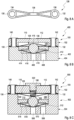
- Figure 1A shows an explosion view of an actuator assembly according to a first embodiment of the present invention.
- Figure 1B shows a perspective view of the actuator assembly 100 according to the first embodiment of the present invention.
- Figure 1C shows a cross-sectional view of the actuator assembly 100 according to the first embodiment of the present invention.
- Figure 1D shows a plan view of the actuator assembly 100 according to the first embodiment of the present invention.
- the actuator assembly 100 comprises at least one substrate 102.
- the substrate is a circuit board member such as a printed circuit board.
- the substrate 102 is made of a material being electrically non-conductive such as fiber-reinforced plastics.
- the substrate comprises a first substrate through hole 104 and a second substrate through hole 106.
- the substrate 102 further comprises an opening 108 which is located substantially in a central portion of the substrate 102.
- the opening is formed rectangular.
- the opening 108 may be located at any position in the substrate as appropriate such as an eccentric position and may have any shape such as rounded, oval, polygonal or polygonal with rounded edges.
- the first substrate through hole 104 and the second substrate through hole 106 are located at opposing ends of the opening 108 such that the opening 108 is located between the first substrate through hole 104 and the second substrate through hole 106.
- the substrate 102 has at least a first circuit path 110. Further, the substrate 102 has a second circuit path 112 mounted on at least one side of the substrate. It is explicitly stated that only one circuit path may be provided and one of the two circuit paths shown in Figures 1A to 1D may be replaced by a cable or the like. In the embodiment shown in Figures 1A to 1D , the first circuit path 110 and the second circuit path 112 are both mounted to a top side 114 of the substrate 102.
- the first circuit path 110 comprises a first support surface 116 defining a first circuit path through hole 118 at one end thereof.
- the first circuit path 110 further comprises a first contact pad 120 at the other end thereof.
- the second circuit path 112 comprises a second support surface 122 defining a second circuit path through hole 124 at one end thereof.
- the second circuit path 112 further comprises a second contact pad 126 at the other end thereof.
- the first circuit path 110 and the second circuit path 112 are made of a material being electrically conductive such as copper.
- the first circuit path 110 and the second circuit path 112 have a thickness and height, respectively, of at least 25 ⁇ m, preferably at least 30 ⁇ m, and comprise a thin coating made from an electrically well-conducting, non-corrosive material such as gold.
- the first circuit path 110 and the second circuit path 112 are spatially separated and insulated from one another.
- the substrate 102 may be made from an electrically conductive material such as copper or aluminum having the advantage, among other things, of having a better thermal conductivity than common insulating substrate materials.
- the substrate comprises a thin coating made of an electrically insulating material provided between the substrate outer surface and within the first substrate through hole 104 and the second substrate through hole 106.
- the actuator assembly 100 further comprises at least one actuator 128 made at least partially of a shape memory material.
- the shape memory material is a shape memory alloy such as NiTi or NiTiCu.
- the shape memory material is a shape memory polymer comprising electrically conductive surface structures reaching from the first actuator through hole 134 to the second actuator through hole 136 which are suitable to act as resistive heating elements.
- the actuator 128 comprises at least a first end 130 and a second end 132.
- the first end 130 comprises a first actuator through hole 134.
- the second end 132 comprises a second actuator through hole 136.
- the actuator 128 is formed substantially planar at least at the first end 130 and/or second end 132.
- the first end 130 and the second end 132 of the actuator 128 are connected to one another by means of at least one actuating section 138, which is two intersecting straight bridges with the first embodiment.
- the actuator 128 is disposed on the first circuit path 110 and the second circuit path 112. More particularly, the actuator 128 is supported at the first support surface 116 with the first end 130, is supported at the second support surface 122 with the second end 132 and the actuating section 138 extends across the opening 108 of the substrate 102.
- the first actuator through hole 134, the first circuit path through hole 118 and the first substrate through hole 104 overlap one another.
- the second actuator through hole 136, the second circuit path through hole 124 and the second substrate through hole 106 overlap one another.
- the first circuit path 110 and the second circuit path 112 on the one hand side and the actuator 128 on the other hand side are located on the same side of the substrate 102 which is the top side 114 with the first embodiment.
- the actuator assembly 100 further comprises at least one fixing member 140.
- the fixing member 140 is a rivet such as a hollow rivet.
- two fixing members are present which are indicated as first fixing member 140 and second fixing member 142. Unless otherwise stated, all explanations below apply to both fixing members 140, 142.
- the first fixing member 140 extends through the first actuator through hole 134, the first circuit path through hole 118 and the first substrate through hole 104 such that the actuator 128 is permanently fixed to the substrate 102 and the first circuit path 110 at least at the first end 130 by means of the first fixing member 140.
- the second fixing member 142 extends through the second actuator through hole 136, the second circuit path through hole 124 and the second substrate through hole 106 such that the actuator 128 is permanently fixed to the substrate 102 and the second circuit path 112 at the second end 132 by means of the second fixing member 142.
- the respective collars or heads of the fixing members 140, 142 press the actuator 128, the circuit paths 110, 112 and the substrate 102 onto one another such that the fixation thereof is not releasable without destroying these constructional members.
- the actuator 128 is electrically connected to the first circuit path 110 and the second circuit path 112 by means of the fixing members 140, 142 as these press the actuator 128 at the first end 130 and the second end 132, respectively, onto the first support surface 116 and the second support surface 122, respectively.
- the fixing members 140, 142 may be made of a material being electrically conductive or electrically non-conductive.
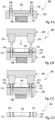
- FIGS 2A to 2D show an apparatus 200 for manufacturing the actuator assembly 100 according to the first embodiment of the present invention with different manufacturing steps.
- the apparatus 200 comprises a lower part 202 and an upper part 204.
- the lower part 202 comprises a base 206 having at least two holding members 208 for holding the substrate 102, the actuator 128 at a first end 130 thereof and at least one fixing member 140, 142 in a predetermined position relative to one another. More particularly, the holding members 208 are configured to hold the substrate 102, the actuator 128 at the first end 130 and at a second end 132 thereof, and at least two fixing members 140, 142 in a predetermined position relative to one another.
- the upper part 204 comprises at least two pressing members 210.
- the upper part 204 and the lower part 202 are moveable towards one another such that the pressing members 210 engage the holding members 208, wherein an engagement of the pressing members 210 and the holding members 208 is configured to press and deform the fixing member 140 such that the actuator 128 is permanently fixed to the substrate 102 and the first circuit path 110 at least at the first end 130.
- the lower part 202 and the upper part 204 are rigidly connected by a linear bearing, assuring their precise alignment (not shown in the figure).
- the upper part 204 is pressed upon the lower part 202 by a pneumatic or hydraulic drive (not shown in the figure).
- the engagement of the pressing members 210 and the holding members 208 is configured to press and deform the fixing members 140, 142 such that the actuator 128 is permanently fixed to the substrate 102, the first circuit path 110 at the first end 130 and the second circuit path 112 at the second end 132.
- the holding members 208 are commonly biased towards the upper part 204 by means of a spring 212.
- the holding members 208 may be independently from one another biased towards the upper part 204. In this case, each holding member 208 is associated with a separate spring.
- the method comprises providing at least one fixing member 140, 142.
- the fixing members 140, 142 are rivets such as hollow rivets.
- the rivets may comprise an electrically well conducting, non-corrosive surface coating such as gold.
- Onto each of the holding members 208 one of the fixing members 140, 142 is disposed.
- the actuator 128 is provided onto each of the holding members 208. The actuator 128 is disposed onto the holding members 208 such that the first fixing member 140 is inserted through the first actuator through hole 134 and the second fixing member 142 is inserted through the second actuator through hole 136.
- the method further comprises providing the substrate 102.
- the substrate 102 is disposed onto the holding members 208 such that the first circuit path 110 and the second circuit path 112 face the actuator 128. More particularly, the substrate 102 and the actuator 128 are arranged such that the first actuator through hole 134, the first circuit path through hole 118 and the first substrate through hole 104 overlap one another. Further, the substrate 102 and the actuator 128 are arranged such that the second actuator through hole 136, the second circuit path through hole 124 and the second substrate through hole 106 overlap one another.
- the first fixing member 140 is inserted through the first actuator through hole 134, the first circuit path through hole 118 and the first substrate through hole 104.
- the second fixing member 142 is inserted through the second actuator through hole 136, the second circuit path through hole 124 and the second substrate through hole 106.
- the upper part 204 and the lower part 202 are moved towards one another such that the pressing members 210 engage the holding members 208.
- the fixing members 140, 142 are pressed and deformed so as to permanently fix the actuator 128 to the substrate 102 and the first circuit path 110 at least at the first end 130 by means of the first fixing member and to permanently fix the actuator 128 to the substrate 102 and the second circuit path 112 at the second end 132 by means of the second fixing member 142.
- Figure 2D shows a cross-sectional view of the actuator assembly 100 manufactured with this method.
- the actuator assembly 100 is removed from the apparatus 200.
- the actuator 128 is concertedly permanently fixed to the substrate 102, the first circuit path 110 and the second circuit path 112 at first end 130 and at the second end 132 by means of the fixing members 140, 142.
- the actuator 128 is electrically connected to the first circuit path 110 and the second circuit path 112 at first end 130 and at the second end 132 by means of the fixing members 140, 142.
- the substrate 102 may be disposed onto the lower part 202 with the fixing members 140, 142 first and then the actuator 128 is disposed. This can be used if the substrate does not have a plane surface for the disposition of the actuator.
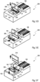
- Figures 3A to 3F show a modification of the apparatus 200 for manufacturing the actuator assembly 100. It has to be noted that the upper part 204 is not shown in Figures 3A to 3F for sake of transparency.
- the modified apparatus 200 further comprises a supply device 214 configured to supply a plurality of actuators 128 connected to one another to the lower part 202. Merely as an example, the plurality of actuators 128 are shown as being connected to one another in a row.
- the supply device 214 is a roller configured to convey the plurality of actuators 128 in a linear manner.
- the modified apparatus 200 further comprises a separating device 216 configured to separate one of the plurality of actuators 128.
- the separating device 216 is a knife configured to cut-off the first actuator 128 in the row as seen in the conveying direction of the supply device 214 from the remaining actuators 128 when being convey to the lower part 202.
- the modified apparatus 200 further comprises a moving device 218 configured to move the lower part 202 towards a first position in which the separated actuator 128 is disposable on the holding members 208 and a second position in which the lower part 202 is engageable by the upper part 204.
- the moving device 218 is a device similar to a carriage device or a shuttle device configured to linearly move the lower part 202 between the first position and second position.
- the method comprises providing a plurality of actuators 128 connected to one another in a row.
- the actuators 128 may be connected to one another by means of small bars at the first ends 130 and the second ends 132, respectively.
- the method further comprises providing at least one fixing member 140, 142.
- the fixing members 140, 142 are rivets such as hollow rivets.
- the supply device 214 supplies the plurality of actuators 128 connected to one another in a row towards the lower part 202. More particularly, the base 206 of the lower part 202 is in a lowered position and the first actuator 128 in the row is supplied to a position above the lower part 202 by means of the supply device 214.
- the moving device 218 has moved the lower part 202 to the first position.
- FIG. 3C which is a perspective view of the modified apparatus 200
- the base 206 of the lower part 202 is raised such that the first fixing member 140 is inserted through the first actuator through hole 134 and the second fixing member 142 is inserted through the second actuator through hole 136.
- the first actuator 128 in the row is disposed onto the holding members 208.
- the separating device 216 is lowered so as to cut-off the first actuator 128 in the row from the remaining actuators 128. Thereby, the first actuator 128 in the row is separated from the remaining actuators 128.
- the moving device 218 moves the lower part 202 to the second position and away from the supply device 214 or the separating device 216.
- the method further comprises providing the substrate 102.
- the substrate 102 is disposed onto the holding members 208 such that the first circuit path 110 and the second circuit path 112 face away from the actuator 128.
- the actuator 128 on the one hand side and the first circuit path 110 and the second circuit path 112 on the other hand side are located on opposing sides of the substrate 102.
- the substrate 102 may be disposed onto the holding members 208 such that the first circuit path 110 and the second circuit path 112 face towards the actuator 128. More particularly, the substrate 102 and the actuator 128 are arranged such that the first actuator through hole 134, the first circuit path through hole 118 and the first substrate through hole 104 overlap one another.
- the substrate 102 and the actuator 128 are arranged such that the second actuator through hole 136, the second circuit path through hole 124 and the second substrate through hole 106 overlap one another.
- the first fixing member 140 is inserted through the first actuator through hole 134, the first circuit path through hole 118 and the first substrate through hole 104.
- the second fixing member 142 is inserted through the second actuator through hole 136, the second circuit path through hole 124 and the second substrate through hole 106.
- the upper part 204 and the lower part 202 are moved towards one another such that the pressing members 210 engage the holding members 208.
- the fixing members 140, 142 are pressed and deformed so as to permanently fix the actuator 128 to the substrate 102 and the first circuit path 110 at least at the first end 130 by means of the first fixing member and to permanently fix the actuator 128 to the substrate 102 and the second circuit path 112 at the second end 132 by means of the second fixing member 142.
- the actuator assembly 100 is removed from the apparatus 200.
- the actuator 128 is concertedly permanently fixed to the substrate 102, the first circuit path 110 and the second circuit path 112 at first end 130 and at the second end 132 by means of the fixing members 140, 142. Further, the actuator 128 is electrically connected to the first circuit path 110 and the second circuit path 112 at first end 130 and at the second end 132 by means of the fixing members 140, 142.
- Figures 4A to 4H show cross-sectional views of actuator assemblies 100 according to second to ninth embodiments of the present invention.
- the actuator assemblies shown in Figures 4A to 4H represent variations of the general principle of the present disclosure. General advantages of some of the variations are (especially when more than one actuator is mounted to a substrate):
- a cavity The purpose of a cavity is to allow the one or more actuator(s) to be deflected "into" the substrate and/or omit friction of the actuator and the substrate when an actuator is moving in parallel to the substrate.
- Figure 4A shows a cross-sectional view of an actuator assembly 100 according to a second embodiment of the present invention.
- the substrate 102 comprises a cavity 144.
- the first circuit path 110 and the second circuit path 112 (not shown in detail) on the one hand side and the actuator 128 on the other hand side are located on the same side of the substrate 102 which is the top side 114. Needless to say, only one circuit path may be present as described above.
- the actuator 128 is disposed at least on the first circuit path 110. More particularly, the actuator 128 is supported at the first support surface 116 with the first end 130.
- the first actuator through hole 134, the first circuit path through hole 118 and the first substrate through hole 104 overlap one another.
- the actuator 128 extends above the cavity 144. Only one fixing member 140 is present.
- the fixing member 140 extends through the first actuator through hole 134, the first circuit path through hole 118 and the first substrate through hole 104.
- the actuator 128 directly contacts the first circuit path 110 at its first end 130.
- the fixing member 140 presses the first end 130 of the actuator 128 onto the first support surface 116 of the first circuit path 110.
- the actuator 128 is electrically connected to the first circuit path 110 by means of the fixing member 140.
- the fixing member 140 does not necessarily be made of an electrically conductive material.
- Figure 4B shows a cross-sectional view of an actuator assembly 100 according to a third embodiment of the present invention.
- the substrate 102 comprises a cavity 144.
- the first circuit path 110 and the second circuit path 112 (not shown in detail) on the one hand side and the actuator 128 on the other hand side are located on opposing sides of the substrate 102. Needless to say, only one circuit path may be present as described above. While the actuator 128 is directly located on the top side 114 of the substrate 102, the first circuit path 110 and the second circuit path 112 are located on the lower side 146 of the substrate 102.
- the first actuator through hole 134, the first circuit path through hole 118 and the first substrate through hole 104 overlap one another.
- the actuator 128 extends above the cavity 144. Only one fixing member 140 is present.
- the fixing member 140 extends through the first actuator through hole 134, the first circuit path through hole 118 and the first substrate through hole 104
- the fixing member 140 is made of an electrically conductive material or comprises a coating made of an electrically conductive material. Even though the actuator 128 does not directly contact the first circuit path 110 at its first end 130, the actuator 128 is electrically connected to the first circuit path 110 by means of the fixing member 140.
- FIG. 4C shows a cross-sectional view of an actuator assembly 100 according to a fourth embodiment of the present invention.
- the substrate 102 comprises a cavity 144.
- two actuators 128 are present.
- a first circuit path 110 and a second circuit path 112 having the design as described above.
- the substrate 102 comprises first substrate through hole 104.
- first substrate through holes 104 present.
- the first circuit paths 110 and the second circuit paths 112 (not shown in detail) on the one hand side and the actuators 128 on the other hand side are located on opposing sides of the substrate 102. Needless to say, only one circuit path per actuator 128 may be present as described above. While the actuators 128 are directly located on the top side 114 of the substrate 102, the first circuit paths 110 and the second circuit paths 112 are located on the lower side 146 of the substrate 102. Concerning each of the actuators 128, the first actuator through hole 134, the first circuit path through hole 118 and the first substrate through hole 104 overlap one another. The actuators 128 extend above the cavity 144.
- each fixing member 140 is made of an electrically conductive material or comprises a coating made of an electrically conductive material. Even though the actuators 128 do not directly contact the associated first circuit path 110 at its first end 130, the actuators 128 are electrically connected to the first circuit path 110 by means of the fixing member 140.
- Figure 4D shows a cross-sectional view of an actuator assembly 100 according to a fifth embodiment of the present invention.
- the substrate 102 comprises a cavity 144.
- two actuators 128 are present.
- a first circuit path 110 and a second circuit path 112 having the design as described above.
- the substrate 102 comprises a first substrate through hole 104.
- first substrate through holes 104 there are two first substrate through holes 104 present.
- the actuators 128 are located on opposing sides of the substrate 102. Concerning each of the actuator 128, the first circuit path 110 and the actuator 128 on the one hand side and the second circuit path 112 on the other hand side are located on opposing sides of the substrate 102.
- One of the actuators 128 extends above the cavity 144.
- each fixing member 140 may be made of an electrically conductive material or comprises a coating made of an electrically conductive material.
- the actuators 128 are electrically connected to the first circuit path 110 by means of the fixing member 140.
- Figure 4E shows a cross-sectional view of an actuator assembly 100 according to a sixth embodiment of the present invention.
- the substrate 102 comprises two cavities 144 located on opposing sides of the substrate 102.
- two actuators 128 are present.
- a first circuit path 110 and a second circuit path 112 (not shown in detail) having the design as described above.
- a first circuit path 110 Associated with each of the two actuators 128, is a first circuit path 110 and a second circuit path 112 (not shown in detail) having the design as described above.
- a second circuit path 112 not shown in detail
- the substrate 102 comprises a single first substrate through hole 104.
- the actuators 128 are located on opposing sides of the substrate 102.
- Concerning each of the actuator 128, the first circuit path 110 and the actuator 128 are located on opposing sides of the substrate 102.
- Each actuator 128 extends above one of the cavities 144.
- a single fixing member 140 extends through the first actuator through holes 134, the first circuit path through holes 118 and the single first substrate through hole 104.
- a single fixing member 140 is sufficient to permanently fix two actuators 128 at their first ends 130 to the first circuit paths 110 and to the substrate 102.
- the fixing member 140 may be made of an electrically conductive material or comprises a coating made of an electrically conductive, preferably non-corrosive material.
- the actuators 128 are electrically connected to the first circuit path 110 by means of the fixing member 140.
- Figure 4F shows a cross-sectional view of an actuator assembly 100 according to a seventh embodiment of the present invention.
- the substrate 102 comprises two cavities 144 located on the same side of the substrate 102.
- two actuators 128 are present.
- a single first circuit path 110 and a second circuit path 112 (not shown in detail) having the design as described above.
- a single first circuit path 110 and a second circuit path 112 (not shown in detail) having the design as described above.
- the substrate 102 comprises a single first substrate through hole 104.
- the actuators 128 are located on the same side of the substrate 102 and one on top of the other. More particularly, the first circuit path 110 and both actuator 128 are located on the same side of the substrate 102. Thus, both actuators 128 share the first circuit path 110. Concerning the actuators 128, the first actuator through holes 134, the first circuit path through holes 118 and the single first substrate through hole 104 overlap one another. Each actuator 128 extends above one of the cavities 144. Concerning each of the actuators 128, a single fixing member 140 extends through the first actuator through holes 134, the first circuit path through hole 118 and the single first substrate through hole 104.
- a single fixing member 140 is sufficient to permanently fix two actuators 128 at their first ends 130 to the first circuit paths 110 and to the substrate 102.
- the fixing member 140 may be made of an electrically conductive material or comprises a coating made of an electrically conductive, preferably non-corrosive material.
- the actuators 128 are electrically connected to the first circuit path 110 by means of the fixing member 140. This design allows to reduce the constructional space as a common ground electrode may be used for both actuators, the second electrode must be provided separately in order to allow both actuators to be individually or independently on one another operated.
- Figure 4G shows a cross-sectional view of an actuator assembly 100 according to an eighth embodiment of the present invention.
- two substrates 102 are present, each of which comprises a cavity 144.
- a single actuator 128 and two first circuit paths 110 and two second circuit path 112 (not shown in detail) having the design as described above.
- the substrate 102 comprises a single first substrate through hole 104.
- the actuator 128 is sandwiched between the substrates 102 and is contacted by the two first circuit paths 110 on opposing sides.
- the first actuator through hole 134, the first circuit path through holes 118 and the single first substrate through hole 104 overlap one another.
- the actuator 128 extends above each of the cavities 144.
- a single fixing member 140 extends through the first actuator through hole 134, the first circuit path through holes 118 and the single first substrate through hole 104.
- the fixing member 140 may be made of an electrically conductive material or comprises a coating made of an electrically conductive material.
- the actuator 128 is electrically connected to the first circuit paths 110 by means of the fixing member 140. This design allows to connect several circuit paths from different substrates to a single actuator and to protect the actuator from the environment or to improve the heat removal.
- Figure 4H shows a cross-sectional view of an actuator assembly 100 according to a ninth embodiment of the present invention.
- the substrate 102 is a flexible substrate.
- a casing 148 is present, which comprises a cavity 144.
- the first circuit path 110 and the second circuit path 112 (not shown in detail) on the one hand side and the actuator 128 on the other hand side are located on the same side of the substrate 102. Needless to say, only one circuit path per actuator 128 may be present as described above. Only one fixing member 140 is present.
- the actuator 128 is permanently fixed to the substrate 102, the first circuit path 110 and the casing 148 at least at the first end 130 by means of the fixing member 140. Particularly, the actuator 128 is sandwiched between the substrate 102 and the casing 148. Thus, the casing 148 serves to mechanically fix the actuators 128, to remove heat from the actuator 128 and to enclose the actuator 128. Further, the flexible substrate may replace a conventional connection cable.
- FIG. 5A shows a plan view of an actuator assembly 100 according to a tenth embodiment of the present invention.
- the actuator assembly 100 according to the tenth embodiment comprises at least two actuators 128 made of a shape memory material.
- the two actuators 128 are located on the same side of the substrate 102.
- each of the actuators 128 is connected to a first circuit path 110 and a second circuit path 112 in the manner as described above.
- the actuators 128 on the one hand side and the first circuit paths 110 and the second circuit paths 112 on the other hand side are located on opposing sides of the substrate.
- the actuators 128 are located on the top side 114 whereas the first circuit paths 110 and the second circuit paths 112 are located on the lower side as indicated by dashed lines.
- the first and second ends 130, 132 of the actuator 128 are connected to one another by means of an undulating or meandering actuating section 138.
- Figure 5B shows a plan view of the actuators 128 of the actuator assembly 100 according to the tenth embodiment of the present invention.
- the at least two actuators 128 are connected to one another by means of an intermediate member 150.
- the intermediate member 150 comprises an orifice 152 such as an aperture.
- the at least two actuators 128 are biased in opposite directions. Thus, a linear actuation movement of the actuators 128 is allowed. If the two or more actuators 128 are not biased against one another, the actuators 128 were in their shape memory state and the application of a heating current to one of the actuators 128 would not result a modification or variation of the shape.
- FIGS 6A to 6G show an apparatus 300 for manufacturing the actuator assembly 100 according to the tenth embodiment of the present invention with different manufacturing steps.
- the apparatus 200 comprises a lower part 302 and an upper part 304.
- the lower part 302 comprises a base 306.
- the base 306 has individually moveable groups 308, 310 of holding members 312 for holding the substrate 102, at least two actuators 128 at the first and second ends 130, 132 thereof and four fixing members 140, 142, 154, 156.
- Each group 308, 310 comprises at least one holding member 312.
- the upper part 304 comprises groups of pressing members 314.
- the upper part 304 and the lower part 302 are moveable towards one another such that the pressing members 314 engage the holding members 312, wherein an engagement of the pressing members 314 and the holding members 312 is configured to press and deform the fixing members 140, 142 such that the at least two actuators are permanently fixed to the substrate 102, the first circuit paths 110 at the first ends 130 and second circuits paths 112 at the second ends 132.
- the groups 308, 310 of holding members 312 are moveable relative to one another in the actuator / substrate plane so as to bias the actuators 128 in opposite directions. In total, there are two groups 308, 310 and four holding members 312.
- the base 306 is divided in base portions 316, 318. Each group 308, 310 is disposed on a separate base portion 316, 318.
- biasing there are also two base portions 316, 318. Further, there is a wedge-shaped lifting device 320 configured to raise so as to move between the base portions 316, 318 and to lower so as to move away from the base portions 316, 318.
- the base portions 316, 318 are laterally moveable which is perpendicular to the moving direction of the lifting device 320.
- this apparatus allows to provide a biasing effect of the actuators, there are other possibilities to provide such a biasing.
- biasing is to be understood merely as an example. Basically, biasing may be realized in different ways, e.g.
- the method comprises providing at least one fixing member 140, 142.
- the fixing members 140, 142 are rivets such as hollow rivets.
- the actuators 128 connected to one another by means of the intermediate member 150 are provided.
- the actuators 128 are disposed onto the holding members 312 such that with each actuator 128 the first fixing member 140 is inserted through the first actuator through hole 134 and the second fixing member 142 is inserted through the second actuator through hole 136.
- the lifting device 320 raises and moves between the base portions 316, 318.
- the base portions 316, 318 move laterally outwards and away from one another.
- the groups 308, 310 of holding members 312 move laterally outwards and away from one another.
- the actuators 128 are stretched as the holding members 312 pull at the first and second ends 130, 132 thereof.
- Figure 6D show the lifting device 320 raised to its uppermost position and the base portions 316, 318 moved laterally outwards to its outermost positions. Thereby the actuators 128 are biased against one another.
- the method further comprises providing the substrate 102.
- the substrate 102 is disposed onto the holding members 312 such that the first circuit paths 110 and the second circuit paths 112 face away from the actuators 128. More particularly, the substrate 102 and the actuators 128 are arranged such that the first actuator through holes 134, the first circuit path through holes 118 and the first substrate through holes 104 overlap one another. Further, the substrate 102 and the actuators 128 are arranged such that the second actuator through holes 136, the second circuit path through holes 124 and the second substrate through holes 106 overlap one another.
- the first fixing member 140 is inserted through the first actuator through hole 134, the first circuit path through hole 118 and the first substrate through hole 104.
- the second fixing member 142 is inserted through the second actuator through hole 136, the second circuit path through hole 124 and the second substrate through hole 106.
- the upper part 304 and the lower part 302 are moved towards one another such that the pressing members 314 engage the holding members 312.
- the fixing members 140, 142 are pressed and deformed so as to permanently fix the actuators 128 to the substrate 102 and the first circuit paths 110 at least at the first ends 130 by means of the first fixing members 140 and to permanently fix the actuators 128 to the substrate 102 and the second circuit paths 112 at the second ends 132 by means of the second fixing members 142.
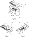
- Figure 6F shows a lower perspective view of the actuator assembly 100 manufactured with this method.
- Figure 6G shows a top perspective view of the actuator assembly 100 manufactured with this method.
- the actuator assembly 100 is removed from the apparatus 300.
- the actuators 128 are concertedly permanently fixed to the substrate 102, the first circuit paths 110 and the second circuit paths 112 at first ends 130 and at the second ends 132 by means of the fixing members 140, 142.
- the actuators 128 are electrically connected to the first circuit paths 110 and the second circuit paths 112 at first ends 130 and at the second ends 132 by means of the fixing members 140, 142.
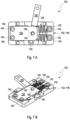
- Figure 7A shows a plan view of an actuator assembly 100 according to an eleventh embodiment of the present invention.
- Figure 7B shows a perspective view of the actuator assembly 100 according to the first embodiment of the present invention.
- the substrate 102 is a casing or casing portion. Such a casing may comprise at least one circuit path, which is preferably formed by selective surface metallization.
- the actuator assembly 100 according to the eleventh embodiment further comprises an elastic resetting member 154 configured to reset the actuator 128 into its original (deflected/deformed) position.
- the elastic resetting member 154 is permanently fixed to the substrate 102 by means of at least one fixing member 140, particularly by means of at least one rivet.
- the substrate 102 comprises a third substrate through hole 156 and a fourth substrate through hole 158 through which the fixing member 140 may be inserted.
- the elastic resetting member 154 is a passive structure, it does not have to be connected to any circuit paths.
- the resetting member 154 may be a thin elastomeric foil.
- the resetting member 154 may be a planar spring fabricated preferably from spring steel or a beryllium copper alloy.
- the first and second ends 130, 132 of the actuator 128 are connected to one another by means of a meandering actuating section 138.
- the actuator 128 is connected to the elastic resetting member 154.
- the first circuit path 110 and the second circuit path 112 are located on the lower side of the substrate 102 which is opposite to the side of the location of the actuator 128.
- the actuator assembly 100 according to the eleventh embodiment further comprises a lever 160.
- the actuator 128 is configured to move the lever 160.
- the actuator 128 is configured to pivot the lever 160 around a pivotal axis 162.
- the actuator 128 comprises a pin 164 engaging an opening or slot 166 of the elastic resetting member 154spaced apart from the pivotal axis 162.
- the resetting member 154 and the actuator 128 are biased against one another.
- the biasing and mounting of the resetting member 154 and the actuator 128 may be made and carried out concertedly with an apparatus similar to the one shown in Figures 6A to 6G .
- the apparatus may be heated to heat the actuators above its shape change temperature Af so as to activate the shape memory effect.
- deformed actuators may retract on their one to smoothen and are easier to be handled.
- the circuit paths may also be used to supply heat from a heating source and/or to measure the electrical resistance of the actuator.
- the actuators do not need to be planar. Rather, coil springs made of a shape memory material or (partially or entirely) flattened wires having through holes may be used for the fixation process.
- the actuator assemblies described herein may be part of a valve such as a gate valve or a seat valve comprising a valve member, a valve seat, and an actuator assembly according to the embodiments described herein.
- the actuator is configured to selectively move the valve member to the valve seat or away from the valve seat so as to close or open the valve as will be describe din further detail below.
- Figures 8A to 8G show different views of two exemplary valves 400, 500. Particularly, Figures 8A to 8G show how to realize seat valves 400, 500 with normally open (NO) and normally closed (NC) functionality based on the present disclosure. As the NO valve 400 and the NC valve 500 are similar in function, both will be described together and the differences from one another are described in further detail.
- NO normally open
- NC normally closed
- Figure 8A shows the actuator 128 of the actuator assembly of Figure 1 in top view.
- Figure 8B shows a cross-section of a normally open (NO) valve 400.
- Fig. 8C shows a cross-section of a normally closed (NC) valve 500.
- Figure 8D shows a perspective bottom view of the actuation part of the NO valve 400.
- Figure 8E shows a perspective bottom view of the actuation part of the NC valve 500.
- Figure 8F shows a perspective top view of the actuation part of the NO valve 400.
- Figure 8G shows a perspective top view of the fluidic part of the NO valve 500 with open valve chamber.
- a seat valve 400, 500 may be realized by combining an actuator assembly 100 based on or similar to the description of Figure 1 with a fluidic part 402, 502. These two parts may be connected e.g. by press-fitting, fixing pins, screws, glue, snap-in mechanisms or any other connection technology.
- the fluidic part 402, 502 as can be best seen in Figures 8B, 8C , 8G comprises a housing part 404, 504 with at least one inlet 406, 506 and at least one outlet 408, 508.
- the inlet 406, 506 ends or terminates in a valve seat 410, 510 within a valve chamber 412, 512.
- the valve chamber 412, 512 is closed above by a membrane 414, 514 fixed on the housing part 404, 504.
- a valve member 416, 516 such as a plunger or sphere is guided and aligned centrically above the valve seat 410, 510 by a valve member guide 418, 518.
- the actuator assembly 100 for the NO valve 400 shown in Figures 8B , 8D, 8F comprises a substrate 102 having an actuator 128 mounted on the bottom side thereof and which substrate 102 contains a cavity 144 allowing the actuator 128 to be deflected out-of-plain into the cavity 144.
- the actuator assembly 100 is assembled on top of the fluidic part 402, 502 in such a way, that the valve member 416 deflects the actuator 128 out-of-plane into the cavity 144.
- positive pressure of the fluid on the inlet 406 may press the membrane 414 with the valve member 416 on top away from the valve seat 410 and thus pass through towards the outlet 408.
- the actuator 128 is additionally deflected into the cavity 144.
- the actuator 128 develops a force pressing the valve member 416 down onto the valve seat 410.
- the membrane 414 in between hinders the fluid from leaving the valve chamber 412 and getting into contact to the actuator 128.
- the actuator assembly for the NC valve 500 shown in Figures 8C , 8E, 8G comprises a substrate 102 having an actuator 128 mounted on the bottom side thereof. It has to be noted that Figure 8G only shows the housing part 504 of the fluidic part 502 for reasons of clarity.
- the substrate 102 comprises an opening 108 for inserting a reset spring 520 such as a compressive helical spring in the center of the actuation section 138.
- reset springs e.g. planar springs, preferably made from spring steel or a copper beryllium alloy.
- the spring 520 is inserted after fixing the actuator 128 on the substrate 102 and the opening 108 is closed by a cap 522, a screw or a similar structure.
- the actuator 128 is deflected out-of-plain away from the substrate 102.
- the actuator assembly 100 is assembled on top of the fluidic part 502 in such a way that the reset spring 520 with the cold actuator 128 below presses the valve member 512 onto the membrane 514 and the valve seat 510, respectively.
- the force of the reset spring 520 holds the valve seat 510 closed against a positive pressure of the fluid on the inlet 506.
- the actuator 128 develops a force pulling the reset spring 520 up and compressing it into the reset spring opening 108.
- the force of the valve member 512 in the valve seat 510 is removed and fluid is free to pass through towards the outlet 508.
Landscapes
- Engineering & Computer Science (AREA)
- Chemical & Material Sciences (AREA)
- Combustion & Propulsion (AREA)
- Mechanical Engineering (AREA)
- General Engineering & Computer Science (AREA)
- Manufacturing & Machinery (AREA)
- Micromachines (AREA)
- Moving Of Heads (AREA)
Claims (17)
- Stellgliedanordnung (100), umfassendmindestens ein Trägermaterial (102), das mindestens eine erste Leiterbahn (110) und/oder eine zweite Leiterbahn (112), die auf mindestens einer Seite des Trägermaterials (102) montiert ist, aufweist,mindestens ein Stellglied (128), das zumindest teilweise aus einem Formgedächtnismaterial, vorzugsweise einer Formgedächtnislegierung, insbesondere NiTi oder NiTiCu, gefertigt ist, wobei das Stellglied (128) mindestens ein erstes Ende (130) und ein zweites Ende (132) umfasst,
undmindestens ein Fixierungselement (140, 142),wobei das erste Ende (130) eine erste Stellglieddurchgangsbohrung (134) umfasst, wobei die erste Leiterbahn (110) eine erste Trägerfläche (116) umfasst, die eine erste Leiterbahndurchgangsbohrung (118) definiert, wobei das Trägermaterial (102) eine erste Trägermaterialdurchgangsbohrung (104) umfasst, wobei die erste Stellglieddurchgangsbohrung (134), die erste Leiterbahndurchgangsbohrung (118) und die erste Trägermaterialdurchgangsbohrung (104) einander überlagern, wobei sich das Fixierungselement (140, 142) durch die erste Stellglieddurchgangsbohrung (134), die erste Leiterbahndurchgangsbohrung (118) und die erste Trägermaterialdurchgangsbohrung (104) erstreckt, sodass das Stellglied (140) zumindest am ersten Ende (130) mittels des Fixierungselements (140, 142) dauerhaft an dem Trägermaterial (102) und der ersten Leiterbahn (110) fixiert ist, und/oder wobei das zweite Ende (132) eine zweite Stellglieddurchgangsbohrung (136) umfasst, wobei die zweite Leitungsbahn (112) eine zweite Trägerfläche (122) umfasst, die eine zweite Leiterbahndurchgangsbohrung (124) definiert, wobei das Trägermaterial (102) eine zweite Trägermaterialdurchgangsbohrung (106) umfasst, wobei die zweite Stellglieddurchgangsbohrung (136), die zweite Leiterbahndurchgangsbohrung (124) und die zweite Trägermaterialdurchgangsbohrung (106) einander überlagern, wobei sich das Fixierungselement (140, 142) durch die zweite Stellglieddurchgangsbohrung (136), die zweite Leiterbahndurchgangsbohrung (124) und die zweite Trägermaterialdurchgangsbohrung (106) erstreckt, wobei das Stellglied am zweiten Ende (132) mittels des Fixierungselements (140, 142) dauerhaft an dem Trägermaterial (102) und der zweiten Leiterbahn (112) fixiert ist. - Stellgliedanordnung (100) nach Anspruch 1, wobei das Fixierungselement (140, 142) ein Niet, vorzugsweise ein Hohlniet, ist wobei der Niet vorzugsweise aus einem elektrisch leitfähigen Material gefertigt ist und/oder eine elektrisch leitfähige Oberflächenbeschichtung aufweist, die vorzugsweise korrosionsbeständig ist.
- Stellgliedanordnung (100) nach einem der Ansprüche 1 bis 2, wobei das Stellglied (128) mit der ersten Leiterbahn (110) und/oder der zweiten Leiterbahn (112) mittels des Fixierungselements (140, 142) elektrisch verbunden ist und wobei das Fixierungselement und/oder die erste Leiterbahn (110) und/oder die zweite Leiterbahn (112) vorzugsweise aus einem elektrisch leitfähigen Material gefertigt ist und/oder eine elektrisch leitfähige Oberflächenbeschichtung aufweist, die vorzugsweise korrosionsbeständig ist.
- Stellgliedanordnung (100) nach einem der Ansprüche 1 bis 3, wobei die erste Leiterbahn (110) und die zweite Leiterbahn (112) einerseits und das Stellglied (128) andererseits auf derselben Seite des Trägermaterials angeordnet sind oder wobei die erste Leiterbahn (110) und die zweite Leiterbahn (112) einerseits und das Stellglied (128) andererseits auf entgegengesetzten Seiten des Trägermaterials angeordnet sind.
- Stellgliedanordnung (100) nach einem der Ansprüche 1 bis 4, ferner umfassend mindestens zwei Stellglieder (128), die aus einem Formgedächtnismaterial gefertigt sind, wobei die mindestens zwei Stellglieder (128) in entgegengesetzte Richtungen vorgespannt sind und wobei die zwei Stellglieder (128) vorzugsweise mittels eines Zwischenelements (150) miteinander verbunden sind.
- Stellgliedanordnung (100) nach einem der Ansprüche 1 bis 5, ferner umfassend zwei Trägermaterialien (102), wobei mindestens eines der Trägermaterialien (102) mindestens eine darauf montierte erste Leiterbahn (110) und/oder zweite Leiterbahn (112) aufweist, wobei das Stellglied (128) zwischen den zwei Trägermaterialien angeordnet ist und/oder wobei mindestens eines der Trägermaterialien (102) ein Gehäuse (148) ist.
- Stellgliedanordnung (100) nach einem der Ansprüche 1 bis 6, wobei das Trägermaterial (102) ein Leiterplattenelement ist und/oder wobei das Trägermaterial (102) flexibel ist und/oder wobei das Trägermaterial (102) ein Gehäuse (148) ist, das mindestens eine Leiterbahn umfasst, die vorzugsweise durch selektive Oberflächenmetallisierung ausgebildet ist.
- Stellgliedanordnung (100) nach einem der Ansprüche 1 bis 7, ferner umfassend ein elastisches Rückstellelement (154), das dazu ausgelegt ist, das Stellglied (128) in seine Ausgangsposition zurückzustellen, wobei das elastische Rückstellelement (154) vorzugsweise mittels mindestens eines Fixierungselements (140, 142), insbesondere mittels mindestens eines Niets, dauerhaft am Trägermaterial (102) fixiert ist.
- Stellgliedanordnung (100) nach Anspruch 8, ferner umfassend einen Hebel (160), wobei das Stellglied (128) dazu ausgelegt ist, den Hebel (160) zu bewegen, insbesondere zu verschwenken.
- Stellgliedanordnung (100) nach einem der Ansprüche 1 bis 9, wobei das Stellglied (128) zumindest am ersten Ende (130) und/oder zweiten Ende (132) im Wesentlichen plan ausgebildet ist, wobei das erste Ende (130) und das zweite Ende (132) des Stellglieds (128) mittels mindestens eines Betätigungsabschnitts (138), der vorzugsweise gerade oder gekrümmt, insbesondere mäandernd, oder Kirigami-artig durch das Einführen einer Vielzahl von geraden oder gekrümmten Einschnitten in das plane Formgedächtnismaterial des Stellglieds (128) ausgebildet ist, miteinander verbunden sind.
- Verfahren zur Herstellung einer Stellgliedanordnung (100), insbesondere einer Stellgliedanordnung (100) nach einem der Ansprüche 1 bis 10, umfassend- Vorsehen mindestens eines ersten Trägermaterials (102), das eine erste Leiterbahn (110) und/oder eine zweite Leiterbahn (112), die auf mindestens einer Seite des Trägermaterials (102) montiert ist, aufweist,- Vorsehen mindestens eines Stellglieds (128), das zumindest teilweise aus einem Formgedächtnismaterial gefertigt ist, wobei das Stellglied (128) mindestens ein erstes Ende (130) und ein zweites Ende (132) umfasst, wobei das erste Ende (130) eine erste Stellglieddurchgangsbohrung (134) umfasst, wobei die erste Leiterbahn (110) eine erste Trägerfläche (116) umfasst, die eine erste Leiterbahndurchgangsbohrung (118) definiert, wobei das Trägermaterial (102) eine erste Trägermaterialdurchgangsbohrung (104) umfasst und/oder wobei das zweite Ende (132) eine zweite Stellglieddurchgangsbohrung (136) umfasst, wobei die zweite Leitungsbahn (112) eine zweite Trägerfläche (122) umfasst, die eine zweite Leiterbahndurchgangsbohrung (124) definiert, wobei das Trägermaterial (102) eine zweite Trägermaterialdurchgangsbohrung (106) umfasst,- Anordnen des Trägermaterials (102) und des Stellglieds (128) derart, dass die erste Stellglieddurchgangsbohrung (134), die erste Leiterbahndurchgangsbohrung (118) und die erste Trägermaterialdurchgangsbohrung (124) einander überlagern und/oder Anordnen des Trägermaterials (102) und des Stellglieds (128) derart, dass die zweite Stellglieddurchgangsbohrung (136), die zweite Leiterbahndurchgangsbohrung (124) und die zweite Trägermaterialdurchgangsbohrung (106) einander überlagern,- Vorsehen mindestens eines Fixierungselements (140, 142), und- Einsetzen des Fixierungselements (140, 142) durch die erste Stellglieddurchgangsbohrung (134), die erste Leiterbahndurchgangsbohrung (134) und die erste Trägermaterialdurchgangsbohrung (118), um das Stellglied (128) zumindest am ersten Ende (130) mittels des Fixierungselements (140, 142) dauerhaft an dem Trägermaterial (102) und der ersten Leiterbahn (110) zu fixieren, und/oder Einsetzen des Fixierungselements (140, 142) durch die zweite Stellglieddurchgangsbohrung (136), die zweite Leiterbahndurchgangsbohrung (124) und die zweite Trägermaterialdurchgangsbohrung (106), um das Stellglied (128) am zweiten Ende (132) mittels des Fixierungselements (140, 142) dauerhaft an dem Trägermaterial (102) und der zweiten Leiterbahn (112) zu fixieren.
- Verfahren nach Anspruch 11, wobei das mindestens eine Stellglied (128) mittels des mindestens einen Fixierungselements (140, 142) an dem Trägermaterial (102), zumindest der ersten Leiterbahn (110) und/oder der zweiten Leiterbahn (112) am ersten Ende (130) und/oder am zweiten Ende (132) des mindestens einen Stellglieds (128) gemeinsam dauerhaft fixiert ist.
- Verfahren nach einem der Ansprüche 11 bis 12, ferner umfassend Vorsehen von mindestens zwei Stellgliedern (128), die aus einem Formgedächtnismaterial gefertigt sind, wobei die mindestens zwei Stellglieder (128) auf derselben Seite des Trägermaterials (102) angeordnet sind, und vorzugsweise ferner umfassend Vorspannen der zwei Stellglieder (128) in entgegengesetzte Richtungen.
- Vorrichtung (200; 300) zur Herstellung einer Stellgliedanordnung (100) nach einem der Ansprüche 1 bis 10, umfassend einen unteren Teil und einen oberen Teil (204; 304), wobei der untere Teil (202; 302) eine Basis (206; 306) umfasst, die mindestens zwei Halteelemente (208; 312) zum Halten des Trägermaterials (102), des Stellglieds (128) an dessen ersten Ende (130) und/oder zweiten Ende (132) und mindestens einen Fixierungselements (140, 142) in einer festgelegten Position zueinander aufweist, wobei der obere Teil (204; 304) mindestens zwei Druckelemente (210; 314) umfasst, wobei der obere Teil (204; 304) und der untere Teil (202; 302) derart aufeinander zu beweglich sind, dass die Druckelemente (210; 314) in die Halteelemente (208; 312) eingreifen, wobei der Eingriff der Druckelemente (210; 314) in die Halteelemente (208; 312) dazu ausgelegt ist, das Fixierungselement (140, 142) derart zusammenzudrücken und zu verformen, dass das Stellglied (128) an zumindest dem ersten Ende (130; 132) dauerhaft an dem Trägermaterial (102) und der ersten Leiterbahn (110) fixiert ist und/oder wobei das Stellglied (128) am zweiten Ende (132) dauerhaft an dem Trägermaterial (102) und der zweiten Leiterbahn (112) fixiert ist.
- Vorrichtung (300) nach Anspruch 14, wobei die Basis (306) individuell bewegliche Gruppen (308, 310) von Halteelementen (312) zum Halten des Trägermaterials (102), mindestens einen Stellglieds (128) an dessen ersten und zweiten Ende (130, 132) und mindestens zwei Fixierungselementen (140, 142) aufweist, wobei jede Gruppe (308, 310) mindestens ein Halteelement (312) umfasst, wobei der obere Teil (304) Gruppen von Druckelementen (314) umfasst, wobei der obere Teil (204; 304) und der untere Teil (202; 302) derart aufeinander zu beweglich sind, dass die Druckelemente (314) in die Halteelemente (312) eingreifen, wobei der Eingriff der Druckelemente (314) in die Halteelemente (312) dazu ausgelegt ist, die Fixierungselemente (140, 142) derart zusammenzudrücken und zu verformen, dass das mindestens eine Stellglied (128) an dem Trägermaterial, der ersten Leiterbahn am ersten Ende und/oder der zweiten Leiterbahn am zweiten Ende dauerhaft fixiert ist, wobei die Gruppen (308, 310) von Halteelementen (312) vorzugsweise in Bezug zueinander derart beweglich sind, dass sie das erste Ende (130) und das zweite Ende (132) eines einzelnen Stellglieds (128) und/oder mindestens zweier Stellglieder (128), die vorzugsweise mittels eines Zwischenelements (150) verbunden sind, in entgegengesetzte Richtungen vorspannen.
- Vorrichtung (200) nach einem der Ansprüche 13 bis 14, ferner umfassend eine Zuführungseinrichtung (214), die dazu ausgelegt ist, mehrere Stellglieder (128), die mit einander verbunden sind, dem unteren Teil (202) zuzuführen, und/oder eine Trennvorrichtung (216), die dazu ausgelegt ist, eines der mehreren Stellglieder (128) zu trennen, und/oder eine Bewegungsvorrichtung (218), die dazu ausgelegt ist, den unteren Teil (202) zu einer ersten Position, in der ein getrenntes Stellglied (128) an den Halteelementen (208) ablegbar ist, und einer zweiten Position, in der der untere Teil (202) von dem oberen Teil (204) eingreifbar ist, zu bewegen.
- Ventil (400; 500), vorzugsweise ein Absperrventil oder ein Sitzventil, umfassend ein Ventilelement (416; 516), einen Ventilsitz (410; 510) und eine Stellgliedanordnung (100) nach einem der Ansprüche 1 bis 10, wobei das Stellglied (128) dazu ausgelegt ist, das Ventilelement (416; 516) selektiv zum Ventilsitz (410; 510) hin- oder vom Ventilsitz (410; 510) wegzubewegen, um das Ventil zu schließen oder zu öffnen.
Priority Applications (2)
| Application Number | Priority Date | Filing Date | Title |
|---|---|---|---|
| EP19171912.9A EP3734065B1 (de) | 2019-04-30 | 2019-04-30 | Aktuatoranordnung |
| US16/860,988 US11136968B2 (en) | 2019-04-30 | 2020-04-28 | Actuator assembly |
Applications Claiming Priority (1)
| Application Number | Priority Date | Filing Date | Title |
|---|---|---|---|
| EP19171912.9A EP3734065B1 (de) | 2019-04-30 | 2019-04-30 | Aktuatoranordnung |
Publications (3)
| Publication Number | Publication Date |
|---|---|
| EP3734065A1 EP3734065A1 (de) | 2020-11-04 |
| EP3734065B1 true EP3734065B1 (de) | 2023-06-07 |
| EP3734065C0 EP3734065C0 (de) | 2023-06-07 |
Family
ID=66349333
Family Applications (1)
| Application Number | Title | Priority Date | Filing Date |
|---|---|---|---|
| EP19171912.9A Active EP3734065B1 (de) | 2019-04-30 | 2019-04-30 | Aktuatoranordnung |
Country Status (2)
| Country | Link |
|---|---|
| US (1) | US11136968B2 (de) |
| EP (1) | EP3734065B1 (de) |
Families Citing this family (3)
| Publication number | Priority date | Publication date | Assignee | Title |
|---|---|---|---|---|
| WO2023006185A1 (en) * | 2021-07-27 | 2023-02-02 | Huawei Technologies Co., Ltd. | Actuator assembly device, aperture system, method of operating an actuator assembly device, and method of operating an aperture system |
| DE102022212011A1 (de) | 2022-11-11 | 2024-05-16 | Memetis Gmbh | Ventil |
| CN118640145A (zh) * | 2024-06-21 | 2024-09-13 | 立讯智造科技(常熟)有限公司 | 致动装置及电子产品 |
Family Cites Families (11)
| Publication number | Priority date | Publication date | Assignee | Title |
|---|---|---|---|---|
| US4337892A (en) | 1980-10-17 | 1982-07-06 | Werner Diermayer | Draft control arrangement for vent of combustion apparatus |
| US4553393A (en) * | 1983-08-26 | 1985-11-19 | The United States Of America As Represented By The Administrator Of The National Aeronautics And Space Administration | Memory metal actuator |
| DE19754747A1 (de) | 1997-12-10 | 1999-06-17 | Impag Gmbh Medizintechnik | Stent zur Implantation im menschlichen Körper sowie Verfahren zur Herstellung desselben |
| US6355501B1 (en) * | 2000-09-21 | 2002-03-12 | International Business Machines Corporation | Three-dimensional chip stacking assembly |
| US7372348B2 (en) * | 2004-08-20 | 2008-05-13 | Palo Alto Research Center Incorporated | Stressed material and shape memory material MEMS devices and methods for manufacturing |
| JP5207591B2 (ja) * | 2006-02-23 | 2013-06-12 | 東レ・ダウコーニング株式会社 | 半導体装置の製造方法および半導体装置 |
| JP5791980B2 (ja) * | 2011-06-30 | 2015-10-07 | 福井鋲螺株式会社 | 締結具及び締結方法 |
| KR101594945B1 (ko) * | 2014-05-07 | 2016-02-17 | 주식회사 성우하이텍 | 리벳 너트 유닛 및 그 장착방법 |
| DE102015111667B4 (de) * | 2015-07-17 | 2025-11-06 | Rogers Germany Gmbh | Substrat für elektrische Schaltkreise und Verfahren zur Herstellung eines derartigen Substrates |
| GB2543052A (en) * | 2015-10-05 | 2017-04-12 | Fluid Automation Syst | Shape memory alloy actuated valve assembly |
| DE102016219245A1 (de) | 2016-10-05 | 2018-04-05 | Schaeffler Technologies AG & Co. KG | Kupplungseinrichtung |
-
2019
- 2019-04-30 EP EP19171912.9A patent/EP3734065B1/de active Active
-
2020
- 2020-04-28 US US16/860,988 patent/US11136968B2/en active Active
Also Published As
| Publication number | Publication date |
|---|---|
| EP3734065A1 (de) | 2020-11-04 |
| US11136968B2 (en) | 2021-10-05 |
| EP3734065C0 (de) | 2023-06-07 |
| US20200347834A1 (en) | 2020-11-05 |
Similar Documents
| Publication | Publication Date | Title |
|---|---|---|
| US11136968B2 (en) | Actuator assembly | |
| US7449817B2 (en) | Actuator and method of manufacturing actuator module | |
| EP2929223B1 (de) | Mikroventil | |
| EP1620349B1 (de) | Mems-stellglieder | |
| CN103874872B (zh) | 记忆合金致动的设备以及其制作及使用方法 | |
| US7331563B2 (en) | Valve with compact actuating mechanism | |
| EP2753830B1 (de) | Aktor mit wenigstens einem thermisches wandlermaterial aufweisenden stellelement | |
| US9027903B2 (en) | Power-efficient actuator assemblies and methods of manufacture | |
| DE60122749T2 (de) | Mikroelektromechanische elektrostatische ventilvorrichtung mit flexibler membrane und deren herstellungsverfahren | |
| US8540206B2 (en) | Multi-stable actuation apparatus and methods for making and using the same | |
| US20080307786A1 (en) | Multi-Stable Actuator Based on Shape Memory Alloy and Touch-Sensitive Interface Using Same | |
| US20070171257A1 (en) | Thermo-buckled micro actuation unit made of polymer of high thermal expansion coefficient | |
| US20060201149A1 (en) | Thin, flexible actuator array to produce complex shapes and force distributions | |
| EP2960497A2 (de) | Thermisches stellelement aus einer formgedächtnislegierung | |
| EP4158194B1 (de) | Aktuatorunterbaugruppe, die von formgedächtnislegierungsdrähten gesteuert wird, system mit einer vielzahl solcher unterbaugruppen und steuerungsverfahren für solch ein system | |
| JPH0722030B2 (ja) | 多接点コネクタ用形状記憶アクチユエ−タ | |
| EP3381578B1 (de) | Düsenklappen servoventil mit torsionsfeder | |
| WO2015189863A2 (en) | A compliant mechanism for refreshable braille display using shape memory alloy | |
| EP2314871A2 (de) | Aktuator | |
| DE102022212011A1 (de) | Ventil | |
| DE102023210274A1 (de) | Durchflussregler | |
| JP2009540622A (ja) | ソレノイドアセンブリ用積層ソレノイドプランジャー | |
| EP2168908A1 (de) | Mikromechanisches thermisches Antriebselement | |
| EP1301346B1 (de) | Knickresistente, thermisch biegende betätiger | |
| JPH05248569A (ja) | 弁体の駆動方法及び弁 |
Legal Events
| Date | Code | Title | Description |
|---|---|---|---|
| PUAI | Public reference made under article 153(3) epc to a published international application that has entered the european phase |
Free format text: ORIGINAL CODE: 0009012 |
|
| STAA | Information on the status of an ep patent application or granted ep patent |
Free format text: STATUS: THE APPLICATION HAS BEEN PUBLISHED |
|
| AK | Designated contracting states |
Kind code of ref document: A1 Designated state(s): AL AT BE BG CH CY CZ DE DK EE ES FI FR GB GR HR HU IE IS IT LI LT LU LV MC MK MT NL NO PL PT RO RS SE SI SK SM TR |
|
| AX | Request for extension of the european patent |
Extension state: BA ME |
|
| STAA | Information on the status of an ep patent application or granted ep patent |
Free format text: STATUS: REQUEST FOR EXAMINATION WAS MADE |
|
| 17P | Request for examination filed |
Effective date: 20201214 |
|
| RBV | Designated contracting states (corrected) |
Designated state(s): AL AT BE BG CH CY CZ DE DK EE ES FI FR GB GR HR HU IE IS IT LI LT LU LV MC MK MT NL NO PL PT RO RS SE SI SK SM TR |
|
| GRAP | Despatch of communication of intention to grant a patent |
Free format text: ORIGINAL CODE: EPIDOSNIGR1 |
|
| STAA | Information on the status of an ep patent application or granted ep patent |
Free format text: STATUS: GRANT OF PATENT IS INTENDED |
|
| INTG | Intention to grant announced |
Effective date: 20221010 |
|
| GRAS | Grant fee paid |
Free format text: ORIGINAL CODE: EPIDOSNIGR3 |
|
| RAP3 | Party data changed (applicant data changed or rights of an application transferred) |
Owner name: MEMETIS GMBH |
|
| GRAA | (expected) grant |
Free format text: ORIGINAL CODE: 0009210 |
|
| STAA | Information on the status of an ep patent application or granted ep patent |
Free format text: STATUS: THE PATENT HAS BEEN GRANTED |
|
| AK | Designated contracting states |
Kind code of ref document: B1 Designated state(s): AL AT BE BG CH CY CZ DE DK EE ES FI FR GB GR HR HU IE IS IT LI LT LU LV MC MK MT NL NO PL PT RO RS SE SI SK SM TR |
|
| REG | Reference to a national code |
Ref country code: GB Ref legal event code: FG4D |
|
| REG | Reference to a national code |
Ref country code: CH Ref legal event code: EP Ref country code: AT Ref legal event code: REF Ref document number: 1575824 Country of ref document: AT Kind code of ref document: T Effective date: 20230615 |
|
| REG | Reference to a national code |
Ref country code: DE Ref legal event code: R096 Ref document number: 602019029759 Country of ref document: DE |
|
| U01 | Request for unitary effect filed |
Effective date: 20230706 |
|
| U07 | Unitary effect registered |
Designated state(s): AT BE BG DE DK EE FI FR IT LT LU LV MT NL PT SE SI Effective date: 20230718 |
|
| REG | Reference to a national code |
Ref country code: LT Ref legal event code: MG9D |
|
| PG25 | Lapsed in a contracting state [announced via postgrant information from national office to epo] |
Ref country code: NO Free format text: LAPSE BECAUSE OF FAILURE TO SUBMIT A TRANSLATION OF THE DESCRIPTION OR TO PAY THE FEE WITHIN THE PRESCRIBED TIME-LIMIT Effective date: 20230907 Ref country code: ES Free format text: LAPSE BECAUSE OF FAILURE TO SUBMIT A TRANSLATION OF THE DESCRIPTION OR TO PAY THE FEE WITHIN THE PRESCRIBED TIME-LIMIT Effective date: 20230607 |
|
| PG25 | Lapsed in a contracting state [announced via postgrant information from national office to epo] |
Ref country code: RS Free format text: LAPSE BECAUSE OF FAILURE TO SUBMIT A TRANSLATION OF THE DESCRIPTION OR TO PAY THE FEE WITHIN THE PRESCRIBED TIME-LIMIT Effective date: 20230607 Ref country code: HR Free format text: LAPSE BECAUSE OF FAILURE TO SUBMIT A TRANSLATION OF THE DESCRIPTION OR TO PAY THE FEE WITHIN THE PRESCRIBED TIME-LIMIT Effective date: 20230607 Ref country code: GR Free format text: LAPSE BECAUSE OF FAILURE TO SUBMIT A TRANSLATION OF THE DESCRIPTION OR TO PAY THE FEE WITHIN THE PRESCRIBED TIME-LIMIT Effective date: 20230908 |
|
| PG25 | Lapsed in a contracting state [announced via postgrant information from national office to epo] |
Ref country code: SK Free format text: LAPSE BECAUSE OF FAILURE TO SUBMIT A TRANSLATION OF THE DESCRIPTION OR TO PAY THE FEE WITHIN THE PRESCRIBED TIME-LIMIT Effective date: 20230607 |
|
| PG25 | Lapsed in a contracting state [announced via postgrant information from national office to epo] |
Ref country code: IS Free format text: LAPSE BECAUSE OF FAILURE TO SUBMIT A TRANSLATION OF THE DESCRIPTION OR TO PAY THE FEE WITHIN THE PRESCRIBED TIME-LIMIT Effective date: 20231007 |
|
| PG25 | Lapsed in a contracting state [announced via postgrant information from national office to epo] |
Ref country code: SM Free format text: LAPSE BECAUSE OF FAILURE TO SUBMIT A TRANSLATION OF THE DESCRIPTION OR TO PAY THE FEE WITHIN THE PRESCRIBED TIME-LIMIT Effective date: 20230607 Ref country code: SK Free format text: LAPSE BECAUSE OF FAILURE TO SUBMIT A TRANSLATION OF THE DESCRIPTION OR TO PAY THE FEE WITHIN THE PRESCRIBED TIME-LIMIT Effective date: 20230607 Ref country code: RO Free format text: LAPSE BECAUSE OF FAILURE TO SUBMIT A TRANSLATION OF THE DESCRIPTION OR TO PAY THE FEE WITHIN THE PRESCRIBED TIME-LIMIT Effective date: 20230607 Ref country code: IS Free format text: LAPSE BECAUSE OF FAILURE TO SUBMIT A TRANSLATION OF THE DESCRIPTION OR TO PAY THE FEE WITHIN THE PRESCRIBED TIME-LIMIT Effective date: 20231007 Ref country code: CZ Free format text: LAPSE BECAUSE OF FAILURE TO SUBMIT A TRANSLATION OF THE DESCRIPTION OR TO PAY THE FEE WITHIN THE PRESCRIBED TIME-LIMIT Effective date: 20230607 |
|
| PG25 | Lapsed in a contracting state [announced via postgrant information from national office to epo] |
Ref country code: PL Free format text: LAPSE BECAUSE OF FAILURE TO SUBMIT A TRANSLATION OF THE DESCRIPTION OR TO PAY THE FEE WITHIN THE PRESCRIBED TIME-LIMIT Effective date: 20230607 |
|
| REG | Reference to a national code |
Ref country code: DE Ref legal event code: R097 Ref document number: 602019029759 Country of ref document: DE |
|
| PLBE | No opposition filed within time limit |
Free format text: ORIGINAL CODE: 0009261 |
|
| STAA | Information on the status of an ep patent application or granted ep patent |
Free format text: STATUS: NO OPPOSITION FILED WITHIN TIME LIMIT |
|
| 26N | No opposition filed |
Effective date: 20240308 |
|
| U20 | Renewal fee for the european patent with unitary effect paid |
Year of fee payment: 6 Effective date: 20240423 |
|
| PG25 | Lapsed in a contracting state [announced via postgrant information from national office to epo] |
Ref country code: MC Free format text: LAPSE BECAUSE OF FAILURE TO SUBMIT A TRANSLATION OF THE DESCRIPTION OR TO PAY THE FEE WITHIN THE PRESCRIBED TIME-LIMIT Effective date: 20230607 |
|
| PG25 | Lapsed in a contracting state [announced via postgrant information from national office to epo] |
Ref country code: MC Free format text: LAPSE BECAUSE OF FAILURE TO SUBMIT A TRANSLATION OF THE DESCRIPTION OR TO PAY THE FEE WITHIN THE PRESCRIBED TIME-LIMIT Effective date: 20230607 |
|
| REG | Reference to a national code |
Ref country code: CH Ref legal event code: PL |
|
| PG25 | Lapsed in a contracting state [announced via postgrant information from national office to epo] |
Ref country code: CH Free format text: LAPSE BECAUSE OF NON-PAYMENT OF DUE FEES Effective date: 20240430 |
|
| PG25 | Lapsed in a contracting state [announced via postgrant information from national office to epo] |
Ref country code: IE Free format text: LAPSE BECAUSE OF NON-PAYMENT OF DUE FEES Effective date: 20240430 |
|
| U20 | Renewal fee for the european patent with unitary effect paid |
Year of fee payment: 7 Effective date: 20250424 |
|
| PG25 | Lapsed in a contracting state [announced via postgrant information from national office to epo] |
Ref country code: CY Free format text: LAPSE BECAUSE OF FAILURE TO SUBMIT A TRANSLATION OF THE DESCRIPTION OR TO PAY THE FEE WITHIN THE PRESCRIBED TIME-LIMIT; INVALID AB INITIO Effective date: 20190430 |
|
| PG25 | Lapsed in a contracting state [announced via postgrant information from national office to epo] |
Ref country code: HU Free format text: LAPSE BECAUSE OF FAILURE TO SUBMIT A TRANSLATION OF THE DESCRIPTION OR TO PAY THE FEE WITHIN THE PRESCRIBED TIME-LIMIT; INVALID AB INITIO Effective date: 20190430 |
|
| U20 | Renewal fee for the european patent with unitary effect paid |
Year of fee payment: 8 Effective date: 20260422 |
|
| PG25 | Lapsed in a contracting state [announced via postgrant information from national office to epo] |
Ref country code: TR Free format text: LAPSE BECAUSE OF FAILURE TO SUBMIT A TRANSLATION OF THE DESCRIPTION OR TO PAY THE FEE WITHIN THE PRESCRIBED TIME-LIMIT Effective date: 20230607 |
|
| PGFP | Annual fee paid to national office [announced via postgrant information from national office to epo] |
Ref country code: GB Payment date: 20260427 Year of fee payment: 8 |