EP3734076B1 - Ölzufuhrmechanismus und horizontalkompressor damit - Google Patents
Ölzufuhrmechanismus und horizontalkompressor damit Download PDFInfo
- Publication number
- EP3734076B1 EP3734076B1 EP18893372.5A EP18893372A EP3734076B1 EP 3734076 B1 EP3734076 B1 EP 3734076B1 EP 18893372 A EP18893372 A EP 18893372A EP 3734076 B1 EP3734076 B1 EP 3734076B1
- Authority
- EP
- European Patent Office
- Prior art keywords
- partition member
- oil
- bearing seat
- pump
- horizontal compressor
- Prior art date
- Legal status (The legal status is an assumption and is not a legal conclusion. Google has not performed a legal analysis and makes no representation as to the accuracy of the status listed.)
- Active
Links
Images


Classifications
-
- F—MECHANICAL ENGINEERING; LIGHTING; HEATING; WEAPONS; BLASTING
- F04—POSITIVE - DISPLACEMENT MACHINES FOR LIQUIDS; PUMPS FOR LIQUIDS OR ELASTIC FLUIDS
- F04C—ROTARY-PISTON, OR OSCILLATING-PISTON, POSITIVE-DISPLACEMENT MACHINES FOR LIQUIDS; ROTARY-PISTON, OR OSCILLATING-PISTON, POSITIVE-DISPLACEMENT PUMPS
- F04C29/00—Component parts, details or accessories of pumps or pumping installations, not provided for in groups F04C18/00 - F04C28/00
- F04C29/02—Lubrication; Lubricant separation
- F04C29/028—Means for improving or restricting lubricant flow
-
- F—MECHANICAL ENGINEERING; LIGHTING; HEATING; WEAPONS; BLASTING
- F04—POSITIVE - DISPLACEMENT MACHINES FOR LIQUIDS; PUMPS FOR LIQUIDS OR ELASTIC FLUIDS
- F04C—ROTARY-PISTON, OR OSCILLATING-PISTON, POSITIVE-DISPLACEMENT MACHINES FOR LIQUIDS; ROTARY-PISTON, OR OSCILLATING-PISTON, POSITIVE-DISPLACEMENT PUMPS
- F04C23/00—Combinations of two or more pumps, each being of rotary-piston or oscillating-piston type, specially adapted for elastic fluids; Pumping installations specially adapted for elastic fluids; Multi-stage pumps specially adapted for elastic fluids
- F04C23/008—Hermetic pumps
-
- F—MECHANICAL ENGINEERING; LIGHTING; HEATING; WEAPONS; BLASTING
- F04—POSITIVE - DISPLACEMENT MACHINES FOR LIQUIDS; PUMPS FOR LIQUIDS OR ELASTIC FLUIDS
- F04C—ROTARY-PISTON, OR OSCILLATING-PISTON, POSITIVE-DISPLACEMENT MACHINES FOR LIQUIDS; ROTARY-PISTON, OR OSCILLATING-PISTON, POSITIVE-DISPLACEMENT PUMPS
- F04C29/00—Component parts, details or accessories of pumps or pumping installations, not provided for in groups F04C18/00 - F04C28/00
- F04C29/02—Lubrication; Lubricant separation
- F04C29/025—Lubrication; Lubricant separation using a lubricant pump
-
- F—MECHANICAL ENGINEERING; LIGHTING; HEATING; WEAPONS; BLASTING
- F04—POSITIVE - DISPLACEMENT MACHINES FOR LIQUIDS; PUMPS FOR LIQUIDS OR ELASTIC FLUIDS
- F04C—ROTARY-PISTON, OR OSCILLATING-PISTON, POSITIVE-DISPLACEMENT MACHINES FOR LIQUIDS; ROTARY-PISTON, OR OSCILLATING-PISTON, POSITIVE-DISPLACEMENT PUMPS
- F04C2240/00—Components
- F04C2240/30—Casings or housings
-
- F—MECHANICAL ENGINEERING; LIGHTING; HEATING; WEAPONS; BLASTING
- F04—POSITIVE - DISPLACEMENT MACHINES FOR LIQUIDS; PUMPS FOR LIQUIDS OR ELASTIC FLUIDS
- F04C—ROTARY-PISTON, OR OSCILLATING-PISTON, POSITIVE-DISPLACEMENT MACHINES FOR LIQUIDS; ROTARY-PISTON, OR OSCILLATING-PISTON, POSITIVE-DISPLACEMENT PUMPS
- F04C2240/00—Components
- F04C2240/50—Bearings
- F04C2240/56—Bearing bushings or details thereof
-
- F—MECHANICAL ENGINEERING; LIGHTING; HEATING; WEAPONS; BLASTING
- F04—POSITIVE - DISPLACEMENT MACHINES FOR LIQUIDS; PUMPS FOR LIQUIDS OR ELASTIC FLUIDS
- F04C—ROTARY-PISTON, OR OSCILLATING-PISTON, POSITIVE-DISPLACEMENT MACHINES FOR LIQUIDS; ROTARY-PISTON, OR OSCILLATING-PISTON, POSITIVE-DISPLACEMENT PUMPS
- F04C2240/00—Components
- F04C2240/80—Other components
- F04C2240/806—Pipes for fluids; Fittings therefor
-
- F—MECHANICAL ENGINEERING; LIGHTING; HEATING; WEAPONS; BLASTING
- F04—POSITIVE - DISPLACEMENT MACHINES FOR LIQUIDS; PUMPS FOR LIQUIDS OR ELASTIC FLUIDS
- F04C—ROTARY-PISTON, OR OSCILLATING-PISTON, POSITIVE-DISPLACEMENT MACHINES FOR LIQUIDS; ROTARY-PISTON, OR OSCILLATING-PISTON, POSITIVE-DISPLACEMENT PUMPS
- F04C2240/00—Components
- F04C2240/80—Other components
- F04C2240/809—Lubricant sump
-
- F—MECHANICAL ENGINEERING; LIGHTING; HEATING; WEAPONS; BLASTING
- F04—POSITIVE - DISPLACEMENT MACHINES FOR LIQUIDS; PUMPS FOR LIQUIDS OR ELASTIC FLUIDS
- F04C—ROTARY-PISTON, OR OSCILLATING-PISTON, POSITIVE-DISPLACEMENT MACHINES FOR LIQUIDS; ROTARY-PISTON, OR OSCILLATING-PISTON, POSITIVE-DISPLACEMENT PUMPS
- F04C29/00—Component parts, details or accessories of pumps or pumping installations, not provided for in groups F04C18/00 - F04C28/00
- F04C29/02—Lubrication; Lubricant separation
- F04C29/026—Lubricant separation
Definitions
- the present invention relates to the field of compressor, and in particular to a horizontal scroll compressor having an improvement on its oil supply mechanism.
- a compressor generally includes a housing, a compression mechanism housed in the housing, a motor that provides power to the compression mechanism, a rotating shaft driven by the motor, and an oil supply mechanism that supplies lubricating oil to various moving parts of the compressor.
- an oil sump is generally provided at the bottom of the compressor housing and an oil pump is provided at the bottom end of the rotating shaft to pump the lubricating oil preserved in the oil sump to an oilhole axially extending in the rotating shaft, thereby supplying lubricating oil to the various moving parts of the compressor.
- a horizontal compressor is required. Since the horizontal compressor cannot naturally form an oil sump at a tail end of the rotating shaft, some oil supply mechanisms for the horizontal compressor are provided to realize the preservation and delivery of lubricating oil.
- a partition plate may be provided to separate out two compartments with a pressure difference (a discharge pressure difference) in the high-pressure region to form in the lower pressure compartment an oil sump which can rise by means of the pressure difference, so that the high-pressure lubricating oil can be delivered to the oil pump (a single oil pump) at the tail end of the rotating shaft.
- the high-temperature and high-pressure lubricating oil in the high-pressure region can be introduced into the oil pump at the tail end of the rotating shaft, and a double-layer housing can be used to form an oil sump in the low-pressure region, or a vertical and straight partition member can be used to separate out an individual oil sump in the low-pressure region.
- EP0809029A2 in an abstract states that "A high-performance compressor is capable of preventing inadequate oil feed even if the compressor tilts or foams and it is also capable of reducing the amount of oil discharged.
- the compressor has a compression element and an electric element housed in a hermetically sealed vessel, the interior of the hermetically sealed vessel being divided into an oil reservoir chamber and a hermetically sealed chamber.
- Two oil pumps are mounted on one end of a rotary shaft and oil is sucked into one of the oil pumps from the oil reservoir chamber and fed to the compression element mounted on the other end of the rotary shaft; oil is sucked into the other oil pump from the hermetically sealed chamber and fed to the oil reservoir chamber.”
- the utility model relates to a pump oil mechanism (PM) of horizontal compressor (1), include: baffle (60) separate accumulator (CO) and are provided with the motor room (CM) of motor (20) in its casing at horizontal compressor (10) to and pump package spare (P), it is including first pump (80) and second pump (90) that are arranged in the accumulator, and first pump aspirates the accumulator with oil from the motor room, during rotation axis (30) interior lubrication passage (34) are supplied with with oil from the accumulator to the second pump.
- baffle (60) separate accumulator (CO) and are provided with the motor room (CM) of motor (20) in its casing at horizontal compressor (10) to and pump package spare (P) it is including first pump (80) and second pump (90) that are arranged in the accumulator, and first pump aspirates the accumulator with oil from the motor room, during rotation axis (30) interior lubrication passage (34) are supplied with with oil from the accumulator to the second pump.
- the partition member includes a partition member body, an inner flange portion serving as a radially inner portion of the partition member, and an outer flange portion serving as a radially outer portion of the partition member, wherein the inner flange portion and the outer flange portion extend toward the oil storage chamber, and, the partition member body, the inner flange portion, and the outer flange portion thereby together define the annular groove.
- a sealing member groove is provided on the inner peripheral surface of the radially inner portion of the partition member and/or on the outer peripheral surface of the bearing seat, and the annular sealing member is accommodated in the sealing member groove.
- the partition member is such configured that the partition member body of the partition member defining the annular groove is offset toward the motor chamber and is closer to one end of the motor.
- the first oil inlet-pipe and/or the second oil inlet-pipe are detachably connected to the pump-bearing seat assembly.
- the first oil inlet-pipe and/or the second oil inlet-pipe have a threaded structure, and thereby can be screwed to the pump-bearing seat assembly, or, the first oil inlet-pipe and/or the second oil inlet-pipe are fixed to the pump-bearing seat assembly by threaded fasteners and positioning pins.
- partition member having the inner flange portion it is possible to realize reliable and stable connection and sealing of the partition member and the bearing seat.
- the partition member having the bent portion protruding toward the oil storage chamber it is possible to reduce or minimize the free space in the motor chamber while appropriately avoiding interference with related components around the bearing seat.
- the horizontal compressor 10 is a low-pressure side scroll compressor.
- the oil supply mechanism 100 according to the present disclosure may be applied to other horizontal compressors.
- the horizontal compressor 10 includes a housing 20, a motor 30, a rotating shaft 40 driven by the motor 30, and a bearing seat 50 supporting the rotating shaft 40.
- the housing 20 includes a housing body 20a, and a first end cover 20b and a second end cover 20c which are respectively provided at two ends of the housing body 20a.
- the horizontal compressor 10 further includes a compression mechanism 60 and a partition plate (muffler plate) 70.
- the compression mechanism 60 is driven by the rotating shaft 40 to compress the working fluid (for example, refrigerant).
- the partition plate 70 separates the internal space defined by the housing 20 (specifically, by the housing body 20a, the first end cover 20b, and the second end cover 20c) into a high-pressure region (located on the left side of the partition plate 70 as shown in Figure 1 ) and a low-pressure region (located on the right side of the partition plate 70 as shown in Figure 1 ).
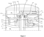
- the oil supply mechanism 100 includes a partition member 120.
- the partition member 120 is in a ring shape (for example, in a substantially circular ring shape) and has a central hole 129 allowing the bearing seat 50 to pass through.
- the partition member 120 is configured to separate out in the housing 20 an oil storage chamber OC and a motor chamber MC in which the motor 30 is provided.
- the oil storage chamber OC located on one side with respect to an axial direction and the motor chamber MC located on the other side with respect to the axial direction are both located in the low-pressure region.
- a radially outer portion of the partition member 120 is connected to an inner peripheral surface 22 of the housing 20 and a radially inner portion of the partition member 120 is connected to an outer peripheral surface 52 of the bearing seat 50.
- the radially outer portion of the partition member 120 is connected to both the housing body 20a and the second end cover 20c. In this way, the three of the housing body 20a, the second end cover 20c and the partition member 120 can be more stably engaged together.
- the partition member 120 is configured to have an annular groove 128 opening toward the oil storage chamber OC.
- the partition member 120 includes a partition member body 121, an inner flange portion 122 serving as a radially inner portion of the partition member 120 that extends away from the oil storage chamber OC , an outer flange portion 123 serving as a radially outer portion of the partition member 120 that extends toward the oil storage chamber OC , and a bent portion 124 provided between the partition member body 121 and the inner flange portion 122 and protruding toward the oil storage chamber OC.
- the partition member body 121, the outer flange portion 123, and the bent portion 124 together define the annular groove 128. That is, the annular groove 128 is reliably formed by the partition member 120 itself without resorting to other components such as the bearing seat 50.
- a ridge 123a is provided on an outer peripheral surface of the radially outer portion (that is, the outer flange portion 123) of the partition member 120.
- the ridge 123a is interposed between the housing body 20a and the end cover 20c of the housing 20. In this way, after the housing body 20a and the second end cover 20c are assembled together, the three of the housing body 20a, the second end cover 20c and the partition member 120 are conveniently, for example, welded together at the ridge 123a from the outside of the housing 20.
- the oil supply mechanism 100 further includes an annular sealing member 140 provided between the radially inner portion (that is, the inner flange portion 122) of the partition member 120 and the outer peripheral surface 52 of the bearing seat 50.
- the partition member 120 and the bearing seat 50 can be connected to each other by the annular sealing member 140 (herein, the partition member 120 and the bearing seat 50 may or may not contact each other).
- the connection and sealing between the partition member 120 and the bearing seat 50 can be realized simply by means of the annular sealing member 140 without resorting to other fastening devices.
- a sealing member groove 122a may be provided on the inner peripheral surface of the radially inner portion of the partition member 120 (that is, the inner flange portion 122), and the annular sealing member 140 can be accommodated in the sealing member groove 122a.
- a sealing member groove 52a (shown in Figure 2 ) may be provided on the outer peripheral surface 52 of the bearing seat 50, and the annular sealing member 140 can be accommodated in the sealing member groove 52a.
- a sealing member groove for accommodating the annular sealing member 140 may be provided on both the inner peripheral surface of the radially inner portion of the partition member 120 and the outer peripheral surface 52 of the bearing seat 50. Since the sealing member groove for accommodating the annular sealing member 140 is provided, the connection and sealing between the partition member 120 and the bearing seat 50 can be further reliably achieved.
- the partition member 120 is an integral part formed by a deep drawing process.
- the partition member 120 is such configured that the partition member body 121 of the partition member 120 defining the annular groove 128 is offset toward the motor chamber MC (offset toward the motor chamber MC relative to the flange portion or the bent portion) and is closer to one end of the motor 30.
- the annular groove 128 of the partition member 120 can thereby have a greater depth.
- the oil supply mechanism 100 further includes a pump device 160 attached to the bearing seat 50 at one end of the rotating shaft 40 (the end where the bearing seat 50 is provided).
- the pump device 160 and the bearing seat 50 (which may be assembled together in advance) constitute a pump-bearing seat assembly.
- the pump device 160 includes a first pump 162 configured to deliver the lubricating oil in the motor chamber MC to the oil storage chamber OC.
- An oil inlet-pipe 162a and an oil discharge pipe 162b for the first pump 162 are provided. Particularly, a first port of the oil discharge pipe 162b is connected to the pump-bearing seat assembly on the motor chamber side, and a second port of the oil discharge pipe 162b enters the oil storage chamber OC from the motor chamber side through an opening 127 provided at the partition member 120.
- the split-type oil discharge pipe 162b located outside the pump-bearing seating assembly By providing the split-type oil discharge pipe 162b located outside the pump-bearing seating assembly, a functional test (quality inspection) can be conveniently performed on the first pump 162, and, compared with a solution in which an oil discharge passage is provided inside the pump-bearing seat assembly, the structure is simplified and improper increase in the axial length of the pump-bearing seat assembly (especially the bearing seat) due to the provision of the oil discharge passage inside the pump-bearing seat assembly is avoided.
- the pump device 160 furthers include a second pump 164 configured to deliver the lubricating oil in the oil storage chamber OC to an oilhole 42 in the rotating shaft 40.
- the first pump 162 and the second pump 164 may be combined together (for example, sharing a partition plate therebetween) to form a so-called double pump structure.
- the pumpage (for example, capacity) of the first pump 162 may be greater than that of the second pump 164.
- the horizontal compressor 10 includes a bearing seat bracket 59 for fixing the bearing seat 50.
- the partition member 120 is a different member from the bearing seat bracket 59.
- the partition member 120 for defining the oil storage chamber OC is independent of the bearing seat bracket 59 for supporting the bearing seat 50.
- the oil storage chamber OC can be formed more reliably, the stable support of the bearing seat 50 can be more reliably achieved, and the connection and sealing between the partition member 120 and the bearing seat 50 is possible to be realized simply by the annular sealing member 140 without resorting to other fastening devices.
- the partition member defines the annular groove having a larger depth opening toward the oil storage chamber by means of, for example, the deep drawing process, it is possible to reduce or minimize the free space (useless free space) in the motor chamber, and the overall size (especially the axial size) of the horizontal compressor can be reduced when the size of the oil storage chamber is fixed.
- the partition member which has the annular groove and the outer flange portion extending toward the oil storage chamber, it is possible to reduce or minimize the free space in the motor chamber while allowing the partition member to be connected respectively with the housing body and the end cover so as to realize a stable engagement of the partition member, the housing body and the end cover.
- partition member having the inner flange portion it is possible to realize reliable and stable connection and sealing of the partition member and the bearing seat.
- the partition member having the bent portion protruding toward the oil storage chamber it is possible to reduce or minimize the free space in the motor chamber while appropriately avoiding interference with related components around the bearing seat.
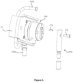
- a variant of the oil supply mechanism 100 is described with reference to Figures 7 , 8a, and 8b .
- the partition member 120 of the oil supply mechanism 100 is not manufactured by the deep drawing process and the partition member body 121 of the partition member 120 is substantially straight.
- the first oil inlet-pipe 162a for the first pump 162 and the second oil inlet-pipe 164a for the second pump 164 are not pipes (for example, straight pipes) extending substantially vertically downward from the pump-bearing seat assembly but bent pipes connected by, for example, brazing.
- the partition member 120 is similarly provided with the annular groove 128 opening toward the oil storage chamber OC, advantageous effects similar to the above exemplary embodiments can also be achieved.
- the split-type oil discharge pipe 162b located outside the pump-bearing seat assembly is also provided, a functional test (quality inspection) can also be conveniently performed on the first pump 162, and, compared with a solution in which an oil discharge passage is provided inside the pump-bearing seat assembly, the structure is also simplified and improper increase in the axial length of the pump-bearing seat assembly (especially the bearing seat) due to the provision of the oil discharge passage inside the pump-bearing seat assembly is avoided.
- partition member 120 is also an integral part formed by the deep drawing process, but the partition member 120 does not include the bent portion and the extending direction of the inner flange portion 122' is different.
- the partition member 120 includes a partition member body 121, an inner flange portion 122' serving as a radially inner portion of the partition member 120, and an outer flange portion 123 serving as a radially outer portion of the partition member 120, wherein the inner flange portion 122' and the outer flange portion 123 extend toward the oil storage chamber OC, and, the partition member body 121, the inner flange portion 122', and the outer flange portion 123 thereby together define the annular groove 128.
- advantageous effects similar to the above exemplary embodiments can also be achieved.
- the oil supply mechanism 100 may also have other possible variants.
- the partition member 120 may not be provided with the annular groove 128 opening toward the oil storage chamber OC but be provided with a split-type oil discharge pipe 162b located outside the pump-bearing seat assembly.
- one or more technical features described above may be incorporated in the technical solution that the annular groove 128 is not provided but the split-type oil discharge pipe 162b located outside the pump-bearing seat assembly is provided, as long as this incorporation is technically compatible.
Landscapes
- Engineering & Computer Science (AREA)
- Mechanical Engineering (AREA)
- General Engineering & Computer Science (AREA)
- Applications Or Details Of Rotary Compressors (AREA)
- Rotary Pumps (AREA)
- Compressor (AREA)
Claims (13)
- Horizontalkompressor (10), umfassend ein Gehäuse (20), einen Motor (30), eine sich drehende Welle (40), die von dem Motor (30) angetrieben wird, einen Lagersitz (50), der die sich drehende Welle (40) trägt, und einen Ölzuführmechanismus,wobei der Ölzuführmechanismus (100) ein Trennelement (120) umfasst, wobei das Trennelement (120) ringförmig ist und eine zentrale Öffnung (129) aufweist, die ermöglicht, dass der Lagersitz (50) hindurchführen kann, und wobei das Trennelement (120) dazu ausgelegt ist, in dem Gehäuse (20) eine Ölbevorratungskammer (OC) und eine Motorkammer (MC), in der der Motor (30) bereitgestellt ist, zu separieren,wobei das Trennelement (120) dazu ausgelegt ist, eine ringförmige Nut (128) aufzuweisen, die sich in Richtung der Ölbevorratungskammer (OC) öffnet, und dadurch gekennzeichnet, dassder Horizontalkompressor (10) ferner eine Lagersitzklammer (59) zum Befestigen des Lagersitzes (50) umfasst und das Trennelement (120) ein anderes Element als die Lagersitzklammer (59) ist.
- Horizontalkompressor (10) nach Anspruch 1, wobei ein radial äußerer Abschnitt des Trennelements (120) mit einer Innenumfangsfläche (22) des Gehäuses (20) verbunden ist und ein radial innerer Abschnitt des Trennelements (120) mit einer Außenumfangsfläche (52) des Lagersitzes (50) verbunden ist.
- Horizontalkompressor (10) nach Anspruch 1, wobei das Gehäuse (20) einen Gehäusekörper (20a) und eine Endabdeckung (20c) umfasst und ein radial äußerer Abschnitt des Trennelements (120) sowohl mit dem Gehäusekörper (20a) als auch mit der Endabdeckung (20c) verbunden ist.
- Horizontalkompressor (10) nach Anspruch 1, wobei das Trennelement (120) einen Trennelementkörper (121) einen inneren Flanschabschnitt, der als ein radial innerer Abschnitt des Trennelements (120) dient, der sich von der Ölbevorratungskammer (OC) weg erstreckt, einen äußeren Flanschabschnitt (123), der als ein radial äußerer Abschnitt des Trennelements (120) dient, der sich in Richtung der Ölbevorratungskammer (OC) hin erstreckt, und einen gebogenen Abschnitt (124), der zwischen dem Trennelementkörper (121) und dem inneren Flanschabschnitt bereitgestellt ist und in Richtung der Ölbevorratungskammer (OC) vorsteht, umfasst, wodurch der Trennelementkörper (121), der äußere Flanschabschnitt (123) und der gebogene Abschnitt (124) zusammen die ringförmige Nut (128) definieren.
- Horizontalkompressor (10) nach Anspruch 1, wobei das Trennelement (120) einen Trennelementkörper (121), einen inneren Flanschabschnitt, der als ein radial innerer Abschnitt des Trennelements (120) dient, und einen äußeren Flanschabschnitt (123), der als ein radial äußerer Abschnitt des Trennelements (120) dient, umfasst, wobei sich der innere Flanschabschnitt und der äußere Flanschabschnitt (123) in Richtung der Ölbevorratungskammer (OC) erstrecken, wodurch der Trennelementkörper (121), der innere Flanschabschnitt und der äußere Flanschabschnitt (123) zusammen die ringförmige Nut (128) definieren.
- Horizontalkompressor (10) nach einem der Ansprüche 2 bis 5, wobei der Ölzuführmechanismus (100) ferner ein ringförmiges Dichtelement (140) umfasst, das zwischen dem radial inneren Abschnitt des Trennelements (120) und der Außenumfangsfläche (52) des Lagersitzes (50) bereitgestellt ist.
- Horizontalkompressor (10) nach Anspruch 6, wobei eine Dichtelementnut (122a, 52a) an einer Innenumfangsfläche des radial inneren Abschnitts des Trennelements (120) und/oder an der Außenumfangsfläche (52) des Lagersitzes (50) bereitgestellt ist und das ringförmige Dichtelement (140) in der Dichtelementnut (122a, 52a) aufgenommen ist.
- Horizontalkompressor (10) nach einem der Ansprüche 2 bis 5, wobei eine Rippe (123a) an einer Außenumfangsfläche des radial äußeren Abschnitts des Trennelements (120) bereitgestellt ist und die Rippe (123a) zwischen einem Gehäusekörper (20a) und einer Endabdeckung (20c) des Gehäuses (20) angeordnet ist.
- Horizontalkompressor (10) nach einem der Ansprüche 1 bis 5, wobei das Trennelement (120) ein einstückiges Teil ist, das durch einen Tiefziehprozess gebildet ist, und das Trennelement (120) vorzugsweise auf eine solche Weise ausgelegt ist, dass ein Trennelementkörper (121) des Trennelements (120), der die ringförmige Nut (128) definiert, in Richtung der Motorkammer (MC) versetzt ist und sich näher an einem Ende des Motors (30) befindet.
- Horizontalkompressor (10) nach einem der Ansprüche 1 bis 5, wobei:der Ölzuführmechanismus (100) ferner eine Pumpvorrichtung (160) umfasst, die an einem Ende der sich drehenden Welle (40) an dem Lagersitz (50) angebracht ist, wobei die Pumpvorrichtung (160) und der Lagersitz (50) eine Pumpen-Lagersitz-Anordnung bilden und die Pumpvorrichtung (160) eine erste Pumpe (162) umfasst, die dazu ausgelegt ist, in der Motorkammer (MC) befindliches Schmieröl der Ölbevorratungskammer (OC) zuzuführen, undder Ölzuführmechanismus (100) mit einem Ölabgaberohr (162b) für die erste Pumpe (162) versehen ist, eine erste Öffnung des Ölabgaberohrs (162b) mit der Pumpen-Lagersitz-Anordnung verbunden ist und eine zweite Öffnung des Ölabgaberohrs (162b) durch eine Öffnung (127), die an dem Trennelement (120) bereitgestellt ist, in die Ölbevorratungskammer (OC) eintritt.
- Horizontalkompressor (10) nach einem der Ansprüche 1 bis 5, wobei:der Ölzuführmechanismus (100) ferner eine Pumpvorrichtung (160) umfasst, die an einem Ende der sich drehenden Welle (40) an dem Lagersitz (50) angebracht ist, wobei die Pumpvorrichtung (160) und der Lagersitz (50) eine Pumpen-Lagersitz-Anordnung bilden, wobei die Pumpvorrichtung (160) eine erste Pumpe (162), die dazu ausgelegt ist, in der Motorkammer (MC) befindliches Schmieröl der Ölbevorratungskammer (OC) zuzuführen, und eine zweite Pumpe (164), die dazu ausgelegt ist, in der Ölbevorratungskammer (OC) befindliches Schmieröl einem Ölloch (42) in der sich drehenden Welle (40) zuzuführen, umfasst, undsich ein erstes Öleinlassrohr (162a) für die erste Pumpe (162) und ein zweites Öleinlassrohr (164a) für die zweite Pumpe (164) im Wesentlichen von der Pumpen-Lagersitz-Anordnung auf einer Motorkammerseite beziehungsweise auf einer Ölbevorratungskammerseite vertikal nach unten erstrecken.
- Horizontalkompressor (10) nach Anspruch 11, wobei das erste Öleinlassrohr (162a) und/oder das zweite Öleinlassrohr (164a) lösbar mit der Pumpen-Lagersitz-Anordnung verbunden sind und das erste Öleinlassrohr (162a) und/oder das zweite Öleinlassrohr (164a) vorzugsweise eine Gewindestruktur aufweisen und mit der Pumpen-Lagersitz-Anordnung verschraubt sind oder das erste Öleinlassrohr (162a) und/oder das zweite Öleinlassrohr (164a) über eine mit einem Gewinde versehene Befestigungsvorrichtung (174) und einen Positionierstift (172) an der Pumpen-Lagersitz-Anordnung befestigt sind.
- Horizontalkompressor (10) nach einem der Ansprüche 1 bis 12, wobei es sich bei dem Horizontalkompressor (10) um einen niederdruckseitigen Scroll-Kompressor handelt.
Applications Claiming Priority (2)
| Application Number | Priority Date | Filing Date | Title |
|---|---|---|---|
| CN201721861898.7U CN207795583U (zh) | 2017-12-27 | 2017-12-27 | 供油机构和具有该供油机构的卧式压缩机 |
| PCT/CN2018/123893 WO2019129057A1 (zh) | 2017-12-27 | 2018-12-26 | 供油机构和具有该供油机构的卧式压缩机 |
Publications (4)
| Publication Number | Publication Date |
|---|---|
| EP3734076A1 EP3734076A1 (de) | 2020-11-04 |
| EP3734076A4 EP3734076A4 (de) | 2021-06-09 |
| EP3734076B1 true EP3734076B1 (de) | 2023-12-20 |
| EP3734076C0 EP3734076C0 (de) | 2023-12-20 |
Family
ID=63279359
Family Applications (1)
| Application Number | Title | Priority Date | Filing Date |
|---|---|---|---|
| EP18893372.5A Active EP3734076B1 (de) | 2017-12-27 | 2018-12-26 | Ölzufuhrmechanismus und horizontalkompressor damit |
Country Status (4)
| Country | Link |
|---|---|
| US (1) | US11603843B2 (de) |
| EP (1) | EP3734076B1 (de) |
| CN (1) | CN207795583U (de) |
| WO (1) | WO2019129057A1 (de) |
Families Citing this family (4)
| Publication number | Priority date | Publication date | Assignee | Title |
|---|---|---|---|---|
| CN207795583U (zh) * | 2017-12-27 | 2018-08-31 | 艾默生环境优化技术(苏州)有限公司 | 供油机构和具有该供油机构的卧式压缩机 |
| WO2020061998A1 (en) | 2018-09-28 | 2020-04-02 | Emerson Climate Technologies, Inc. | Compressor oil management system |
| US11953001B2 (en) | 2021-07-15 | 2024-04-09 | Samsung Electronics Co., Ltd. | Horizontal type rotary compressor and home appliance including the same |
| US12092111B2 (en) | 2022-06-30 | 2024-09-17 | Copeland Lp | Compressor with oil pump |
Family Cites Families (16)
| Publication number | Priority date | Publication date | Assignee | Title |
|---|---|---|---|---|
| US3434656A (en) * | 1967-09-14 | 1969-03-25 | Worthington Corp | Lubrication system for rotary vane compressors |
| JP2895320B2 (ja) | 1992-06-12 | 1999-05-24 | 三菱重工業株式会社 | 横型密閉圧縮機 |
| JP3408309B2 (ja) * | 1994-02-10 | 2003-05-19 | 株式会社東芝 | 密閉形コンプレッサならびにこのコンプレッサを用いた冷凍装置 |
| TW316940B (de) * | 1994-09-16 | 1997-10-01 | Hitachi Ltd | |
| TW362142B (en) | 1996-05-23 | 1999-06-21 | Sanyo Electric Co | Horizontal compressor |
| JP3874469B2 (ja) * | 1996-10-04 | 2007-01-31 | 株式会社日立製作所 | スクロール圧縮機 |
| JP3956432B2 (ja) * | 1997-06-18 | 2007-08-08 | 松下電器産業株式会社 | 密閉型圧縮機 |
| JP4152678B2 (ja) | 2002-06-13 | 2008-09-17 | 松下電器産業株式会社 | スクロール圧縮機 |
| JP2007218214A (ja) | 2006-02-20 | 2007-08-30 | Hitachi Ltd | 密閉形スクロール圧縮機 |
| JP2008008161A (ja) | 2006-06-27 | 2008-01-17 | Sanden Corp | 圧縮機 |
| DE102008013784B4 (de) * | 2007-03-15 | 2017-03-23 | Denso Corporation | Kompressor |
| JP5150564B2 (ja) * | 2009-06-22 | 2013-02-20 | 日立アプライアンス株式会社 | 横置型密閉式圧縮機 |
| JP5277283B2 (ja) | 2011-05-13 | 2013-08-28 | 日立アプライアンス株式会社 | スクロール圧縮機およびそれを搭載した冷凍サイクル |
| CN106812701B (zh) | 2015-12-02 | 2019-04-16 | 上海海立电器有限公司 | 压缩机壳体以及卧式压缩机 |
| CN205578273U (zh) * | 2016-05-03 | 2016-09-14 | 艾默生环境优化技术(苏州)有限公司 | 泵油机构及具有该泵油机构的卧式压缩机 |
| CN207795583U (zh) | 2017-12-27 | 2018-08-31 | 艾默生环境优化技术(苏州)有限公司 | 供油机构和具有该供油机构的卧式压缩机 |
-
2017
- 2017-12-27 CN CN201721861898.7U patent/CN207795583U/zh active Active
-
2018
- 2018-12-26 EP EP18893372.5A patent/EP3734076B1/de active Active
- 2018-12-26 WO PCT/CN2018/123893 patent/WO2019129057A1/zh not_active Ceased
- 2018-12-26 US US16/957,698 patent/US11603843B2/en active Active
Also Published As
| Publication number | Publication date |
|---|---|
| WO2019129057A1 (zh) | 2019-07-04 |
| EP3734076A4 (de) | 2021-06-09 |
| EP3734076A1 (de) | 2020-11-04 |
| US20200362863A1 (en) | 2020-11-19 |
| CN207795583U (zh) | 2018-08-31 |
| EP3734076C0 (de) | 2023-12-20 |
| US11603843B2 (en) | 2023-03-14 |
Similar Documents
| Publication | Publication Date | Title |
|---|---|---|
| EP3734076B1 (de) | Ölzufuhrmechanismus und horizontalkompressor damit | |
| US9651044B2 (en) | Electric compressor | |
| KR101728261B1 (ko) | 스크롤형 압축기 | |
| JP5868247B2 (ja) | ロータリー式圧縮機 | |
| EP2312164B1 (de) | Spiralverdichter | |
| US9651047B2 (en) | Compressor having a partitioned discharge chamber | |
| US11781548B2 (en) | Oil separation apparatus and horizontal compressor | |
| KR101971819B1 (ko) | 스크롤 압축기 | |
| JP5880513B2 (ja) | 圧縮機 | |
| CN111140495A (zh) | 涡旋压缩机 | |
| US10436201B2 (en) | Scroll compressor provided with a lubrication system | |
| KR20100030634A (ko) | 탠덤 컴프레서 시스템 및 방법 | |
| US11913455B2 (en) | Scroll compressor having a centrifugal oil pump | |
| CN106194750A (zh) | 涡旋压缩机 | |
| CN106499634A (zh) | 电动压缩机 | |
| CN218151299U (zh) | 储液器和具有其的制冷剂泵 | |
| EP3409948A1 (de) | Hermetischer zweistufiger verdichter | |
| US20240052838A1 (en) | A compressor | |
| JP2006348928A (ja) | 圧縮機 | |
| JP2014134166A (ja) | スクロール型圧縮機 | |
| JP2019190468A (ja) | スクロール圧縮機 | |
| CN209925203U (zh) | 涡旋压缩机及其静涡旋盘、空调及车辆 | |
| KR20260037534A (ko) | 스크롤 압축기 | |
| WO2025205479A1 (ja) | 両回転式スクロール型圧縮機 | |
| KR101828957B1 (ko) | 스크롤 압축기 |
Legal Events
| Date | Code | Title | Description |
|---|---|---|---|
| STAA | Information on the status of an ep patent application or granted ep patent |
Free format text: STATUS: THE INTERNATIONAL PUBLICATION HAS BEEN MADE |
|
| PUAI | Public reference made under article 153(3) epc to a published international application that has entered the european phase |
Free format text: ORIGINAL CODE: 0009012 |
|
| STAA | Information on the status of an ep patent application or granted ep patent |
Free format text: STATUS: REQUEST FOR EXAMINATION WAS MADE |
|
| 17P | Request for examination filed |
Effective date: 20200703 |
|
| AK | Designated contracting states |
Kind code of ref document: A1 Designated state(s): AL AT BE BG CH CY CZ DE DK EE ES FI FR GB GR HR HU IE IS IT LI LT LU LV MC MK MT NL NO PL PT RO RS SE SI SK SM TR |
|
| AX | Request for extension of the european patent |
Extension state: BA ME |
|
| DAV | Request for validation of the european patent (deleted) | ||
| DAX | Request for extension of the european patent (deleted) | ||
| A4 | Supplementary search report drawn up and despatched |
Effective date: 20210507 |
|
| RIC1 | Information provided on ipc code assigned before grant |
Ipc: F04C 29/02 20060101AFI20210430BHEP Ipc: F04C 23/00 20060101ALI20210430BHEP |
|
| GRAP | Despatch of communication of intention to grant a patent |
Free format text: ORIGINAL CODE: EPIDOSNIGR1 |
|
| STAA | Information on the status of an ep patent application or granted ep patent |
Free format text: STATUS: GRANT OF PATENT IS INTENDED |
|
| INTG | Intention to grant announced |
Effective date: 20230630 |
|
| GRAS | Grant fee paid |
Free format text: ORIGINAL CODE: EPIDOSNIGR3 |
|
| GRAA | (expected) grant |
Free format text: ORIGINAL CODE: 0009210 |
|
| STAA | Information on the status of an ep patent application or granted ep patent |
Free format text: STATUS: THE PATENT HAS BEEN GRANTED |
|
| AK | Designated contracting states |
Kind code of ref document: B1 Designated state(s): AL AT BE BG CH CY CZ DE DK EE ES FI FR GB GR HR HU IE IS IT LI LT LU LV MC MK MT NL NO PL PT RO RS SE SI SK SM TR |
|
| REG | Reference to a national code |
Ref country code: GB Ref legal event code: FG4D |
|
| REG | Reference to a national code |
Ref country code: CH Ref legal event code: EP |
|
| REG | Reference to a national code |
Ref country code: DE Ref legal event code: R096 Ref document number: 602018063057 Country of ref document: DE |
|
| REG | Reference to a national code |
Ref country code: IE Ref legal event code: FG4D |
|
| RAP4 | Party data changed (patent owner data changed or rights of a patent transferred) |
Owner name: COPELAND CLIMATE TECHNOLOGIES (SUZHOU) CO., LTD. |
|
| U01 | Request for unitary effect filed |
Effective date: 20240112 |
|
| U07 | Unitary effect registered |
Designated state(s): AT BE BG DE DK EE FI FR IT LT LU LV MT NL PT SE SI Effective date: 20240123 |
|
| PG25 | Lapsed in a contracting state [announced via postgrant information from national office to epo] |
Ref country code: GR Free format text: LAPSE BECAUSE OF FAILURE TO SUBMIT A TRANSLATION OF THE DESCRIPTION OR TO PAY THE FEE WITHIN THE PRESCRIBED TIME-LIMIT Effective date: 20240321 |
|
| PG25 | Lapsed in a contracting state [announced via postgrant information from national office to epo] |
Ref country code: ES Free format text: LAPSE BECAUSE OF FAILURE TO SUBMIT A TRANSLATION OF THE DESCRIPTION OR TO PAY THE FEE WITHIN THE PRESCRIBED TIME-LIMIT Effective date: 20231220 |
|
| PG25 | Lapsed in a contracting state [announced via postgrant information from national office to epo] |
Ref country code: GR Free format text: LAPSE BECAUSE OF FAILURE TO SUBMIT A TRANSLATION OF THE DESCRIPTION OR TO PAY THE FEE WITHIN THE PRESCRIBED TIME-LIMIT Effective date: 20240321 Ref country code: ES Free format text: LAPSE BECAUSE OF FAILURE TO SUBMIT A TRANSLATION OF THE DESCRIPTION OR TO PAY THE FEE WITHIN THE PRESCRIBED TIME-LIMIT Effective date: 20231220 |
|
| PG25 | Lapsed in a contracting state [announced via postgrant information from national office to epo] |
Ref country code: RS Free format text: LAPSE BECAUSE OF FAILURE TO SUBMIT A TRANSLATION OF THE DESCRIPTION OR TO PAY THE FEE WITHIN THE PRESCRIBED TIME-LIMIT Effective date: 20231220 Ref country code: NO Free format text: LAPSE BECAUSE OF FAILURE TO SUBMIT A TRANSLATION OF THE DESCRIPTION OR TO PAY THE FEE WITHIN THE PRESCRIBED TIME-LIMIT Effective date: 20240320 Ref country code: HR Free format text: LAPSE BECAUSE OF FAILURE TO SUBMIT A TRANSLATION OF THE DESCRIPTION OR TO PAY THE FEE WITHIN THE PRESCRIBED TIME-LIMIT Effective date: 20231220 |
|
| PG25 | Lapsed in a contracting state [announced via postgrant information from national office to epo] |
Ref country code: IS Free format text: LAPSE BECAUSE OF FAILURE TO SUBMIT A TRANSLATION OF THE DESCRIPTION OR TO PAY THE FEE WITHIN THE PRESCRIBED TIME-LIMIT Effective date: 20240420 |
|
| U21 | Renewal fee for the european patent with unitary effect paid with additional fee |
Year of fee payment: 6 Effective date: 20240529 |
|
| PG25 | Lapsed in a contracting state [announced via postgrant information from national office to epo] |
Ref country code: CZ Free format text: LAPSE BECAUSE OF FAILURE TO SUBMIT A TRANSLATION OF THE DESCRIPTION OR TO PAY THE FEE WITHIN THE PRESCRIBED TIME-LIMIT Effective date: 20231220 |
|
| PG25 | Lapsed in a contracting state [announced via postgrant information from national office to epo] |
Ref country code: SK Free format text: LAPSE BECAUSE OF FAILURE TO SUBMIT A TRANSLATION OF THE DESCRIPTION OR TO PAY THE FEE WITHIN THE PRESCRIBED TIME-LIMIT Effective date: 20231220 |
|
| PG25 | Lapsed in a contracting state [announced via postgrant information from national office to epo] |
Ref country code: SM Free format text: LAPSE BECAUSE OF FAILURE TO SUBMIT A TRANSLATION OF THE DESCRIPTION OR TO PAY THE FEE WITHIN THE PRESCRIBED TIME-LIMIT Effective date: 20231220 Ref country code: SK Free format text: LAPSE BECAUSE OF FAILURE TO SUBMIT A TRANSLATION OF THE DESCRIPTION OR TO PAY THE FEE WITHIN THE PRESCRIBED TIME-LIMIT Effective date: 20231220 Ref country code: RO Free format text: LAPSE BECAUSE OF FAILURE TO SUBMIT A TRANSLATION OF THE DESCRIPTION OR TO PAY THE FEE WITHIN THE PRESCRIBED TIME-LIMIT Effective date: 20231220 Ref country code: IS Free format text: LAPSE BECAUSE OF FAILURE TO SUBMIT A TRANSLATION OF THE DESCRIPTION OR TO PAY THE FEE WITHIN THE PRESCRIBED TIME-LIMIT Effective date: 20240420 Ref country code: CZ Free format text: LAPSE BECAUSE OF FAILURE TO SUBMIT A TRANSLATION OF THE DESCRIPTION OR TO PAY THE FEE WITHIN THE PRESCRIBED TIME-LIMIT Effective date: 20231220 |
|
| REG | Reference to a national code |
Ref country code: CH Ref legal event code: PL |
|
| PG25 | Lapsed in a contracting state [announced via postgrant information from national office to epo] |
Ref country code: PL Free format text: LAPSE BECAUSE OF FAILURE TO SUBMIT A TRANSLATION OF THE DESCRIPTION OR TO PAY THE FEE WITHIN THE PRESCRIBED TIME-LIMIT Effective date: 20231220 |
|
| PG25 | Lapsed in a contracting state [announced via postgrant information from national office to epo] |
Ref country code: PL Free format text: LAPSE BECAUSE OF FAILURE TO SUBMIT A TRANSLATION OF THE DESCRIPTION OR TO PAY THE FEE WITHIN THE PRESCRIBED TIME-LIMIT Effective date: 20231220 |
|
| REG | Reference to a national code |
Ref country code: DE Ref legal event code: R097 Ref document number: 602018063057 Country of ref document: DE |
|
| PG25 | Lapsed in a contracting state [announced via postgrant information from national office to epo] |
Ref country code: MC Free format text: LAPSE BECAUSE OF FAILURE TO SUBMIT A TRANSLATION OF THE DESCRIPTION OR TO PAY THE FEE WITHIN THE PRESCRIBED TIME-LIMIT Effective date: 20231220 |
|
| REG | Reference to a national code |
Ref country code: IE Ref legal event code: MM4A |
|
| PG25 | Lapsed in a contracting state [announced via postgrant information from national office to epo] |
Ref country code: IE Free format text: LAPSE BECAUSE OF NON-PAYMENT OF DUE FEES Effective date: 20231226 |
|
| PG25 | Lapsed in a contracting state [announced via postgrant information from national office to epo] |
Ref country code: CH Free format text: LAPSE BECAUSE OF NON-PAYMENT OF DUE FEES Effective date: 20231231 |
|
| PLBE | No opposition filed within time limit |
Free format text: ORIGINAL CODE: 0009261 |
|
| STAA | Information on the status of an ep patent application or granted ep patent |
Free format text: STATUS: NO OPPOSITION FILED WITHIN TIME LIMIT |
|
| PG25 | Lapsed in a contracting state [announced via postgrant information from national office to epo] |
Ref country code: IE Free format text: LAPSE BECAUSE OF NON-PAYMENT OF DUE FEES Effective date: 20231226 Ref country code: CH Free format text: LAPSE BECAUSE OF NON-PAYMENT OF DUE FEES Effective date: 20231231 |
|
| 26N | No opposition filed |
Effective date: 20240923 |
|
| GBPC | Gb: european patent ceased through non-payment of renewal fee |
Effective date: 20240320 |
|
| PG25 | Lapsed in a contracting state [announced via postgrant information from national office to epo] |
Ref country code: GB Free format text: LAPSE BECAUSE OF NON-PAYMENT OF DUE FEES Effective date: 20240320 |
|
| PG25 | Lapsed in a contracting state [announced via postgrant information from national office to epo] |
Ref country code: GB Free format text: LAPSE BECAUSE OF NON-PAYMENT OF DUE FEES Effective date: 20240320 |
|
| PG25 | Lapsed in a contracting state [announced via postgrant information from national office to epo] |
Ref country code: CY Free format text: LAPSE BECAUSE OF FAILURE TO SUBMIT A TRANSLATION OF THE DESCRIPTION OR TO PAY THE FEE WITHIN THE PRESCRIBED TIME-LIMIT; INVALID AB INITIO Effective date: 20181226 |
|
| U90 | Renewal fees not paid: noting of loss of rights |
Free format text: RENEWAL FEE NOT PAID FOR YEAR 07 Effective date: 20250714 |
|
| PG25 | Lapsed in a contracting state [announced via postgrant information from national office to epo] |
Ref country code: HU Free format text: LAPSE BECAUSE OF FAILURE TO SUBMIT A TRANSLATION OF THE DESCRIPTION OR TO PAY THE FEE WITHIN THE PRESCRIBED TIME-LIMIT; INVALID AB INITIO Effective date: 20181226 |
|
| U93 | Unitary patent lapsed |
Free format text: RENEWAL FEE NOT PAID Effective date: 20241231 |
|
| PG25 | Lapsed in a contracting state [announced via postgrant information from national office to epo] |
Ref country code: TR Free format text: LAPSE BECAUSE OF FAILURE TO SUBMIT A TRANSLATION OF THE DESCRIPTION OR TO PAY THE FEE WITHIN THE PRESCRIBED TIME-LIMIT Effective date: 20231220 |