EP3734082A1 - Système d'entraînement linéaire hydrostatique - Google Patents
Système d'entraînement linéaire hydrostatique Download PDFInfo
- Publication number
- EP3734082A1 EP3734082A1 EP20164176.8A EP20164176A EP3734082A1 EP 3734082 A1 EP3734082 A1 EP 3734082A1 EP 20164176 A EP20164176 A EP 20164176A EP 3734082 A1 EP3734082 A1 EP 3734082A1
- Authority
- EP
- European Patent Office
- Prior art keywords
- fluid
- connection
- cylinder
- hydraulic
- pressure
- Prior art date
- Legal status (The legal status is an assumption and is not a legal conclusion. Google has not performed a legal analysis and makes no representation as to the accuracy of the status listed.)
- Granted
Links
Images


Classifications
-
- F—MECHANICAL ENGINEERING; LIGHTING; HEATING; WEAPONS; BLASTING
- F15—FLUID-PRESSURE ACTUATORS; HYDRAULICS OR PNEUMATICS IN GENERAL
- F15B—SYSTEMS ACTING BY MEANS OF FLUIDS IN GENERAL; FLUID-PRESSURE ACTUATORS, e.g. SERVOMOTORS; DETAILS OF FLUID-PRESSURE SYSTEMS, NOT OTHERWISE PROVIDED FOR
- F15B15/00—Fluid-actuated devices for displacing a member from one position to another; Gearing associated therewith
- F15B15/18—Combined units comprising both motor and pump
-
- F—MECHANICAL ENGINEERING; LIGHTING; HEATING; WEAPONS; BLASTING
- F15—FLUID-PRESSURE ACTUATORS; HYDRAULICS OR PNEUMATICS IN GENERAL
- F15B—SYSTEMS ACTING BY MEANS OF FLUIDS IN GENERAL; FLUID-PRESSURE ACTUATORS, e.g. SERVOMOTORS; DETAILS OF FLUID-PRESSURE SYSTEMS, NOT OTHERWISE PROVIDED FOR
- F15B11/00—Servomotor systems without provision for follow-up action; Circuits therefor
- F15B11/02—Systems essentially incorporating special features for controlling the speed or actuating force of an output member
- F15B11/028—Systems essentially incorporating special features for controlling the speed or actuating force of an output member for controlling the actuating force
- F15B11/036—Systems essentially incorporating special features for controlling the speed or actuating force of an output member for controlling the actuating force by means of servomotors having a plurality of working chambers
-
- F—MECHANICAL ENGINEERING; LIGHTING; HEATING; WEAPONS; BLASTING
- F15—FLUID-PRESSURE ACTUATORS; HYDRAULICS OR PNEUMATICS IN GENERAL
- F15B—SYSTEMS ACTING BY MEANS OF FLUIDS IN GENERAL; FLUID-PRESSURE ACTUATORS, e.g. SERVOMOTORS; DETAILS OF FLUID-PRESSURE SYSTEMS, NOT OTHERWISE PROVIDED FOR
- F15B11/00—Servomotor systems without provision for follow-up action; Circuits therefor
- F15B11/02—Systems essentially incorporating special features for controlling the speed or actuating force of an output member
- F15B11/04—Systems essentially incorporating special features for controlling the speed or actuating force of an output member for controlling the speed
-
- B—PERFORMING OPERATIONS; TRANSPORTING
- B29—WORKING OF PLASTICS; WORKING OF SUBSTANCES IN A PLASTIC STATE IN GENERAL
- B29C—SHAPING OR JOINING OF PLASTICS; SHAPING OF MATERIAL IN A PLASTIC STATE, NOT OTHERWISE PROVIDED FOR; AFTER-TREATMENT OF THE SHAPED PRODUCTS, e.g. REPAIRING
- B29C49/00—Blow-moulding, i.e. blowing a preform or parison to a desired shape within a mould; Apparatus therefor
- B29C49/42—Component parts, details or accessories; Auxiliary operations
- B29C49/56—Opening, closing or clamping means
-
- B—PERFORMING OPERATIONS; TRANSPORTING
- B30—PRESSES
- B30B—PRESSES IN GENERAL
- B30B15/00—Details of, or accessories for, presses; Auxiliary measures in connection with pressing
- B30B15/16—Control arrangements for fluid-driven presses
- B30B15/161—Control arrangements for fluid-driven presses controlling the ram speed and ram pressure, e.g. fast approach speed at low pressure, low pressing speed at high pressure
-
- F—MECHANICAL ENGINEERING; LIGHTING; HEATING; WEAPONS; BLASTING
- F15—FLUID-PRESSURE ACTUATORS; HYDRAULICS OR PNEUMATICS IN GENERAL
- F15B—SYSTEMS ACTING BY MEANS OF FLUIDS IN GENERAL; FLUID-PRESSURE ACTUATORS, e.g. SERVOMOTORS; DETAILS OF FLUID-PRESSURE SYSTEMS, NOT OTHERWISE PROVIDED FOR
- F15B1/00—Installations or systems with accumulators; Supply reservoir or sump assemblies
- F15B1/02—Installations or systems with accumulators
- F15B1/021—Installations or systems with accumulators used for damping
-
- F—MECHANICAL ENGINEERING; LIGHTING; HEATING; WEAPONS; BLASTING
- F15—FLUID-PRESSURE ACTUATORS; HYDRAULICS OR PNEUMATICS IN GENERAL
- F15B—SYSTEMS ACTING BY MEANS OF FLUIDS IN GENERAL; FLUID-PRESSURE ACTUATORS, e.g. SERVOMOTORS; DETAILS OF FLUID-PRESSURE SYSTEMS, NOT OTHERWISE PROVIDED FOR
- F15B1/00—Installations or systems with accumulators; Supply reservoir or sump assemblies
- F15B1/02—Installations or systems with accumulators
- F15B1/024—Installations or systems with accumulators used as a supplementary power source, e.g. to store energy in idle periods to balance pump load
-
- F—MECHANICAL ENGINEERING; LIGHTING; HEATING; WEAPONS; BLASTING
- F15—FLUID-PRESSURE ACTUATORS; HYDRAULICS OR PNEUMATICS IN GENERAL
- F15B—SYSTEMS ACTING BY MEANS OF FLUIDS IN GENERAL; FLUID-PRESSURE ACTUATORS, e.g. SERVOMOTORS; DETAILS OF FLUID-PRESSURE SYSTEMS, NOT OTHERWISE PROVIDED FOR
- F15B11/00—Servomotor systems without provision for follow-up action; Circuits therefor
- F15B11/02—Systems essentially incorporating special features for controlling the speed or actuating force of an output member
- F15B11/022—Systems essentially incorporating special features for controlling the speed or actuating force of an output member in which a rapid approach stroke is followed by a slower, high-force working stroke
-
- F—MECHANICAL ENGINEERING; LIGHTING; HEATING; WEAPONS; BLASTING
- F15—FLUID-PRESSURE ACTUATORS; HYDRAULICS OR PNEUMATICS IN GENERAL
- F15B—SYSTEMS ACTING BY MEANS OF FLUIDS IN GENERAL; FLUID-PRESSURE ACTUATORS, e.g. SERVOMOTORS; DETAILS OF FLUID-PRESSURE SYSTEMS, NOT OTHERWISE PROVIDED FOR
- F15B11/00—Servomotor systems without provision for follow-up action; Circuits therefor
- F15B11/16—Servomotor systems without provision for follow-up action; Circuits therefor with two or more servomotors
- F15B11/17—Servomotor systems without provision for follow-up action; Circuits therefor with two or more servomotors using two or more pumps
-
- F—MECHANICAL ENGINEERING; LIGHTING; HEATING; WEAPONS; BLASTING
- F15—FLUID-PRESSURE ACTUATORS; HYDRAULICS OR PNEUMATICS IN GENERAL
- F15B—SYSTEMS ACTING BY MEANS OF FLUIDS IN GENERAL; FLUID-PRESSURE ACTUATORS, e.g. SERVOMOTORS; DETAILS OF FLUID-PRESSURE SYSTEMS, NOT OTHERWISE PROVIDED FOR
- F15B11/00—Servomotor systems without provision for follow-up action; Circuits therefor
- F15B11/16—Servomotor systems without provision for follow-up action; Circuits therefor with two or more servomotors
- F15B11/22—Synchronisation of the movement of two or more servomotors
-
- F—MECHANICAL ENGINEERING; LIGHTING; HEATING; WEAPONS; BLASTING
- F15—FLUID-PRESSURE ACTUATORS; HYDRAULICS OR PNEUMATICS IN GENERAL
- F15B—SYSTEMS ACTING BY MEANS OF FLUIDS IN GENERAL; FLUID-PRESSURE ACTUATORS, e.g. SERVOMOTORS; DETAILS OF FLUID-PRESSURE SYSTEMS, NOT OTHERWISE PROVIDED FOR
- F15B13/00—Details of servomotor systems ; Valves for servomotor systems
- F15B13/02—Fluid distribution or supply devices characterised by their adaptation to the control of servomotors
- F15B13/06—Fluid distribution or supply devices characterised by their adaptation to the control of servomotors for use with two or more servomotors
-
- F—MECHANICAL ENGINEERING; LIGHTING; HEATING; WEAPONS; BLASTING
- F15—FLUID-PRESSURE ACTUATORS; HYDRAULICS OR PNEUMATICS IN GENERAL
- F15B—SYSTEMS ACTING BY MEANS OF FLUIDS IN GENERAL; FLUID-PRESSURE ACTUATORS, e.g. SERVOMOTORS; DETAILS OF FLUID-PRESSURE SYSTEMS, NOT OTHERWISE PROVIDED FOR
- F15B15/00—Fluid-actuated devices for displacing a member from one position to another; Gearing associated therewith
- F15B15/08—Characterised by the construction of the motor unit
- F15B15/14—Characterised by the construction of the motor unit of the straight-cylinder type
- F15B15/149—Fluid interconnections, e.g. fluid connectors, passages
-
- F—MECHANICAL ENGINEERING; LIGHTING; HEATING; WEAPONS; BLASTING
- F15—FLUID-PRESSURE ACTUATORS; HYDRAULICS OR PNEUMATICS IN GENERAL
- F15B—SYSTEMS ACTING BY MEANS OF FLUIDS IN GENERAL; FLUID-PRESSURE ACTUATORS, e.g. SERVOMOTORS; DETAILS OF FLUID-PRESSURE SYSTEMS, NOT OTHERWISE PROVIDED FOR
- F15B1/00—Installations or systems with accumulators; Supply reservoir or sump assemblies
- F15B1/26—Supply reservoir or sump assemblies
-
- F—MECHANICAL ENGINEERING; LIGHTING; HEATING; WEAPONS; BLASTING
- F15—FLUID-PRESSURE ACTUATORS; HYDRAULICS OR PNEUMATICS IN GENERAL
- F15B—SYSTEMS ACTING BY MEANS OF FLUIDS IN GENERAL; FLUID-PRESSURE ACTUATORS, e.g. SERVOMOTORS; DETAILS OF FLUID-PRESSURE SYSTEMS, NOT OTHERWISE PROVIDED FOR
- F15B2211/00—Circuits for servomotor systems
- F15B2211/20—Fluid pressure source, e.g. accumulator or variable axial piston pump
- F15B2211/205—Systems with pumps
- F15B2211/2053—Type of pump
- F15B2211/20546—Type of pump variable capacity
-
- F—MECHANICAL ENGINEERING; LIGHTING; HEATING; WEAPONS; BLASTING
- F15—FLUID-PRESSURE ACTUATORS; HYDRAULICS OR PNEUMATICS IN GENERAL
- F15B—SYSTEMS ACTING BY MEANS OF FLUIDS IN GENERAL; FLUID-PRESSURE ACTUATORS, e.g. SERVOMOTORS; DETAILS OF FLUID-PRESSURE SYSTEMS, NOT OTHERWISE PROVIDED FOR
- F15B2211/00—Circuits for servomotor systems
- F15B2211/20—Fluid pressure source, e.g. accumulator or variable axial piston pump
- F15B2211/205—Systems with pumps
- F15B2211/2053—Type of pump
- F15B2211/20561—Type of pump reversible
-
- F—MECHANICAL ENGINEERING; LIGHTING; HEATING; WEAPONS; BLASTING
- F15—FLUID-PRESSURE ACTUATORS; HYDRAULICS OR PNEUMATICS IN GENERAL
- F15B—SYSTEMS ACTING BY MEANS OF FLUIDS IN GENERAL; FLUID-PRESSURE ACTUATORS, e.g. SERVOMOTORS; DETAILS OF FLUID-PRESSURE SYSTEMS, NOT OTHERWISE PROVIDED FOR
- F15B2211/00—Circuits for servomotor systems
- F15B2211/20—Fluid pressure source, e.g. accumulator or variable axial piston pump
- F15B2211/205—Systems with pumps
- F15B2211/20576—Systems with pumps with multiple pumps
-
- F—MECHANICAL ENGINEERING; LIGHTING; HEATING; WEAPONS; BLASTING
- F15—FLUID-PRESSURE ACTUATORS; HYDRAULICS OR PNEUMATICS IN GENERAL
- F15B—SYSTEMS ACTING BY MEANS OF FLUIDS IN GENERAL; FLUID-PRESSURE ACTUATORS, e.g. SERVOMOTORS; DETAILS OF FLUID-PRESSURE SYSTEMS, NOT OTHERWISE PROVIDED FOR
- F15B2211/00—Circuits for servomotor systems
- F15B2211/20—Fluid pressure source, e.g. accumulator or variable axial piston pump
- F15B2211/21—Systems with pressure sources other than pumps, e.g. with a pyrotechnical charge
- F15B2211/212—Systems with pressure sources other than pumps, e.g. with a pyrotechnical charge the pressure sources being accumulators
-
- F—MECHANICAL ENGINEERING; LIGHTING; HEATING; WEAPONS; BLASTING
- F15—FLUID-PRESSURE ACTUATORS; HYDRAULICS OR PNEUMATICS IN GENERAL
- F15B—SYSTEMS ACTING BY MEANS OF FLUIDS IN GENERAL; FLUID-PRESSURE ACTUATORS, e.g. SERVOMOTORS; DETAILS OF FLUID-PRESSURE SYSTEMS, NOT OTHERWISE PROVIDED FOR
- F15B2211/00—Circuits for servomotor systems
- F15B2211/20—Fluid pressure source, e.g. accumulator or variable axial piston pump
- F15B2211/27—Directional control by means of the pressure source
-
- F—MECHANICAL ENGINEERING; LIGHTING; HEATING; WEAPONS; BLASTING
- F15—FLUID-PRESSURE ACTUATORS; HYDRAULICS OR PNEUMATICS IN GENERAL
- F15B—SYSTEMS ACTING BY MEANS OF FLUIDS IN GENERAL; FLUID-PRESSURE ACTUATORS, e.g. SERVOMOTORS; DETAILS OF FLUID-PRESSURE SYSTEMS, NOT OTHERWISE PROVIDED FOR
- F15B2211/00—Circuits for servomotor systems
- F15B2211/70—Output members, e.g. hydraulic motors or cylinders or control therefor
- F15B2211/705—Output members, e.g. hydraulic motors or cylinders or control therefor characterised by the type of output members or actuators
- F15B2211/7051—Linear output members
- F15B2211/7055—Linear output members having more than two chambers
-
- F—MECHANICAL ENGINEERING; LIGHTING; HEATING; WEAPONS; BLASTING
- F15—FLUID-PRESSURE ACTUATORS; HYDRAULICS OR PNEUMATICS IN GENERAL
- F15B—SYSTEMS ACTING BY MEANS OF FLUIDS IN GENERAL; FLUID-PRESSURE ACTUATORS, e.g. SERVOMOTORS; DETAILS OF FLUID-PRESSURE SYSTEMS, NOT OTHERWISE PROVIDED FOR
- F15B2211/00—Circuits for servomotor systems
- F15B2211/70—Output members, e.g. hydraulic motors or cylinders or control therefor
- F15B2211/775—Combined control, e.g. control of speed and force for providing a high speed approach stroke with low force followed by a low speed working stroke with high force, e.g. for a hydraulic press
-
- F—MECHANICAL ENGINEERING; LIGHTING; HEATING; WEAPONS; BLASTING
- F15—FLUID-PRESSURE ACTUATORS; HYDRAULICS OR PNEUMATICS IN GENERAL
- F15B—SYSTEMS ACTING BY MEANS OF FLUIDS IN GENERAL; FLUID-PRESSURE ACTUATORS, e.g. SERVOMOTORS; DETAILS OF FLUID-PRESSURE SYSTEMS, NOT OTHERWISE PROVIDED FOR
- F15B2211/00—Circuits for servomotor systems
- F15B2211/70—Output members, e.g. hydraulic motors or cylinders or control therefor
- F15B2211/78—Control of multiple output members
- F15B2211/782—Concurrent control, e.g. synchronisation of two or more actuators
Definitions
- the invention relates to a hydrostatic linear drive system, in particular for a closing unit of a blow molding system.
- Hydrostatic linear drive systems are also used, for example, in hydraulic presses, deep-drawing or injection molding machines. Such machines usually have several motion sequences.
- One of these movement sequences is a so-called force path, in which a high force is exerted at low speed on the workpiece to be machined or the component to be moved.
- Another of these movement sequences is what is known as rapid traverse, with which less force is exerted, but which enables faster movement.
- Such a linear drive system is for example from DE 10 2016 113 882 A1 known.
- the known linear drive system has a hydraulic pump that is reversible in flow direction and is driven by an electric motor.
- the hydraulic pump is used to provide a variable volume flow of hydraulic fluid in a closed hydraulic circuit which includes a first differential cylinder as the master cylinder.
- the annular piston area on the rod side of the differential cylinder is smaller than the piston area on the piston side.
- the closed hydraulic circuit is closed off from its surroundings and has an overpressure in relation to the surroundings during operation. This overpressure is generated in a manner known per se by means of a bias source.
- the drive system requires an expansion tank.
- the expansion tank is preferably designed as a second differential cylinder, the cylinder space of which is open to the environment on the piston side and the annular area of which corresponds to the difference between the piston area and the annular area of the main cylinder.
- the piston rods of the two differential cylinders are mechanically coupled.
- a 2/2-way valve is arranged in the connecting line between the annular space of the second cylinder, which works as a compensation tank, and the annular space of the master cylinder.
- Another 2/2-way valve is arranged in a further connecting line between the annular space of the second cylinder, which works as a compensation tank, and the piston space of the main cylinder.
- the 2/2-way valve between the two annular spaces of the two differential cylinders is opened, while the other 2/2-way valve is blocked.
- the 2/2-way valve between the two annular spaces of the differential cylinder is blocked while the other 2/2-way valve is open.
- the expansion tank designed as a differential cylinder has the consequence that the extension and retraction of the main cylinder in rapid traverse always takes place against the resistance of the second cylinder working as an expansion tank, which means that high traverse speeds in rapid traverse with high forces in the power gear cannot be achieved.
- two 2/2-way valves are absolutely necessary for the operation of the drive system in rapid or power gear.
- the JP 46 14 544 B2 discloses a hydrostatic linear drive system with a 3-surface cylinder, one hydraulically active surface being provided for a power gear and two hydraulically active surfaces for an overdrive gear.
- the 3-surface cylinder is extended and retracted in rapid traverse by means of the two hydraulically active surfaces for high-speed gear, which can optionally be acted upon via a closed hydraulic circuit including a hydraulic pump.
- the cylinder space assigned to the hydraulically active surface for the power transmission is filled with fluid via a pre-tensioned expansion tank when it is extended in rapid traverse.
- this cylinder chamber is in fluid-conducting connection with a pump connected to a tank on the suction side and the pre-stressed expansion tank.
- the pressure of the pre-tensioned expansion tank acts against the extension direction on one of the two hydraulically active surfaces for the overdrive.
- the DE 10 2010 051 140 A1 discloses a linear drive system for a drawing press with a press frame in which a ram carrying an upper tool and a drawing cushion with a drawing cushion plate are mounted on which a workpiece hold-down is supported.
- the die cushion plate is mechanically coupled to the ram via a strut.
- Overdrive cylinders are provided for accelerated actuation of the tool hold-down device for its hydraulically driven up and down movement.
- clamping cylinders designed as plungers are provided on the die cushion plate; they are used to move and apply force to the workpiece hold-down relative to the Die cushion plate. The pistons of the clamping cylinder and the overdrive cylinder are coupled.
- the overdrive cylinders pre-accelerate the hold-down devices and the pistons of the clamping cylinders in the direction of movement of the ram.
- the clamping cylinder chambers are connected to a pretensioned low-pressure accumulator by means of check valves.
- the invention is based on the object of creating a linear drive system which has a simpler and more compact structure with at the same time a higher retraction and extension speed in rapid traverse, higher forces in the power operation and reduced energy consumption.
- the solution to this problem is based on the idea of bringing about the retraction and extension movement in rapid traverse by means of separate hydraulically active surfaces, which are independent of a larger hydraulically active surface that is only acted upon by pressurized hydraulic fluid in the force movement.
- the mechanical and hydraulic resistances are reduced by the fact that the larger hydraulically effective surface does not work against a pressurized hydraulic fluid in rapid traverse, but rather the hydraulic fluid to be displaced from the cylinder chamber is fed to an expansion tank that is open to the environment, ie not preloaded, or is fed to the cylinder chamber hydraulic fluid to be supplied is drawn in from the expansion tank.
- the hydraulically effective surfaces work together, what contributes to high forces with a compact design of the drive system.
- the retraction and extension of the cylinders in rapid traverse is brought about exclusively by the synchronous cylinder integrated into the closed hydraulic circuit.
- the first hydraulically effective surface of the single-acting cylinder is prevented from being subjected to hydraulic fluid.
- the extension of the cylinders in the power transmission is primarily effected by the single-acting cylinder, the first hydraulically effective surface of which is acted upon by the hydraulic fluid in the extension direction.
- the single-acting cylinder is supported during extension by the synchronous cylinder, the second hydraulically active surface of which is also acted upon with hydraulic fluid in the extension direction.
- the mechanical coupling between the single-acting cylinder and the synchronous cylinder takes place in particular via a coupling element between the piston rods of the two cylinders.
- the single-acting cylinder is a plunger cylinder, also referred to as a plunger cylinder.
- the piston rod of the plunger cylinder also serves as a piston.
- Plunger cylinder have a better mechanical efficiency than conventional, single-acting cylinders.
- the embodiment according to independent claim 2 relates to a linear drive system with a cylinder - hereinafter also referred to as a 3-surface cylinder - which integrates the hydraulically active surfaces of the single-acting cylinder and the synchronous cylinder of the embodiment according to independent claim 1 in one component and thus contributes to a particularly compact design.
- the extension and retraction of the 3-surface cylinder in rapid traverse is effected, as in the embodiment according to claim 1, exclusively by applying hydraulic fluid to the second or third hydraulically active surface. In rapid traverse, loading of the larger first hydraulically effective area is prevented.
- the extension of the 3-surface cylinder in power transmission is primarily effected by applying hydraulic fluid to the larger, first hydraulically active surface. However, as in the embodiment according to claim 1, the extension is assisted by acting on the second hydraulically active surface in the extension direction.
- the low-pressure connection of the second hydraulic pump is fluid-conducting with the expansion tank and the high-pressure connection is fluid-conducting with the first fluid connection of the single-acting cylinder in the embodiment according to claim 1 or with the first Fluid connection of the 3-surface cylinder according to claim 2 connected.
- the second hydraulic pump can be designed to be weaker than the first hydraulic pump, since it basically only has to provide the additional volume of hydraulic fluid, while the pressure build-up takes place primarily via the first hydraulic pump.
- a second hydraulic pump with correspondingly larger dimensions in the embodiment according to claim 3 can also make a significant contribution to the pressure build-up in the power transmission.
- the second hydraulic pump in the embodiment according to claim 3 can compensate for leakage oil in the closed hydraulic circuit and preload the closed hydraulic circuit.
- the first and / or second hydraulic pump in an advantageous embodiment of the invention provides a variable volume flow of the hydraulic fluid.
- the displacement volume and / or the drive speed of the first and / or second hydraulic pump can be variable.
- the hydraulic pump is driven, for example, by an electric motor whose speed and direction of rotation can be changed in order to change the volume flow and the direction of flow. If the drive is via an electric motor with a constant speed, the displacement volume of the hydraulic pump can be variable in order to change the volume flow. In the case of a variable displacement pump, the displacement volume is continuously changed, for example, by adjusting a swash plate. When the swash plate is adjusted through the zero position, the direction of flow of the volume flow changes, so that the direction of flow is reversed and the high-pressure and low-pressure sides of the variable displacement pump change.
- a particularly energy-saving operation with optimized overall efficiency is preferably achieved with a combination of a variable speed of the electric motor and a variable displacement volume of the variable displacement pump.
- the pressure connections of the first and / or the second hydraulic pump are connected to a pressure accumulator.
- the connection to the connections is made via check valves, which prevent a backflow from the pressure connections in the direction of the accumulator.
- the check valves open when the pressure at the pressure connections is lower than that in the pressure vessel. The pressure accumulator can therefore improve the dynamics of the linear drive system and / or save energy.
- the pressure connections of the first hydraulic pump are connected to a pressure accumulator, this can also serve as a preload source for the closed hydraulic circuit.
- the preload is primarily generated by means of a hydraulic pump.
- the preload pressure in the closed hydraulic circuit is higher than the ambient pressure.
- Ambient pressure is the hydrostatic pressure of the air at the location where the linear drive system is set up.
- the mean air pressure in the atmosphere is approximately 1 bar according to the standard.
- the preload pressure is 5-50 bar, preferably between 10-25 bar.
- the shut-off devices provided in the hydraulic lines serve the purpose of blocking or releasing the volume flow of the hydraulic fluid.
- the shut-off devices are preferably shut-off valves, in particular 2/2-way valves.
- the 2/2-way valve has two connections and two switching positions. In the first, closed switch position, the flow through the 2/2-way valve is blocked; in the second, open switch position, the flow through the 2/2-way valve is released.
- a throttle is arranged in the fluid-conducting connection between the expansion tank and the first fluid connection on the single-acting cylinder or the 3-surface cylinder.
- the throttle increases the pressure of the hydraulic fluid flowing through the fluid-conducting connection reduced.
- the throttle can be designed as an integral part of the shut-off valve.
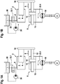
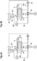
- Figure 1 shows a first embodiment of a hydrostatic linear drive system 1 with a single-acting cylinder 2, which is designed as a plunger cylinder.
- the plunger cylinder comprises a piston rod 3, a first hydraulically active surface 4 and a first cylinder chamber 5 with a first fluid connection 6 for a hydraulic fluid 7.
- the piston rod 3 is also the piston.
- the end face of the piston rod 3 facing the cylinder space 5 is the piston surface and is hydraulically effective.
- the first hydraulically active surface 4 of the single-acting cylinder 2 can be acted upon by the hydraulic fluid 7 in an extension direction 8 via the first fluid connection 6.
- the linear drive system 1 also has a synchronous cylinder 9, which has a piston rod 11, 12 on both sides of the piston 10.
- the annular piston surfaces that surround the piston rods 11, 12 form a second hydraulically active surface 13 and a third hydraulically active surface 14, which are the same in size.
- the synchronous cylinder 9 has a second liquid connection 15 and a third liquid connection 16, the second The fluid connection 15 opens into an annular second cylinder space 35 on the left side of the piston 10 and the third fluid connection 16 opens into a third annular cylinder space 36 on the right side of the piston 10.
- Hydraulic fluid 7 can be applied to second hydraulically active surface 13 in extension direction 8 via second fluid connection 15.
- the third hydraulically active surface 14 can be acted upon with hydraulic fluid 7 in the retraction direction 17 via the third fluid connection 16.
- a closed hydraulic circuit 18 under a preload pressure comprises the synchronous cylinder 9 and a first hydraulic pump 19 with a first and a second pressure connection 21, 22.
- An electric motor 20 drives the hydraulic pump 19 at constant or variable engine speed.
- the hydraulic pump 19 is preferably an axial piston variable displacement pump of the swashplate design. By adjusting the swash plate, the volume flow of the first hydraulic pump 19 can be changed continuously. When adjusting the swash plate through the zero position, the flow direction 23.1, 23.2 of the volume flow changes. The swivel angle is adjusted hydraulically via an actuating piston.
- the first pressure connection 21 is the high pressure side and the second pressure connection 22 is the low pressure side of the first hydraulic pump 19 or vice versa.
- the first pressure connection 21 is connected in a fluid-conducting manner to the second liquid connection 15 and the second pressure connection 22 is connected to the third liquid connection 16 via a hydraulic line 24, 25.
- the bias of the hydraulic fluid in the closed hydraulic circuit 18 can be generated, for example, by a pressure source (not shown) connected to the pressure connections 21, 22 (e.g. feed oil pump). Since the pretensioning of a closed hydraulic circuit 18 is known to the person skilled in the art, the components required for this have not been shown for the sake of clarity.
- a second hydraulic pump 26 with a low-pressure connection 27 and a high-pressure connection 28 is provided to apply hydraulic fluid 7 to the first hydraulically active surface 4 of the single-acting cylinder 2.
- the low-pressure connection 27 is fluid-conducting via a hydraulic line 29 with an expansion tank 30 and the high-pressure connection 28 is fluid-conducting via a hydraulic line 31 with the first liquid connection 6 of the single-acting cylinder 2.
- the expansion tank 30, which is open to the environment, receives hydraulic fluid 7 and is also connected in a fluid-conducting manner via a hydraulic line 32 to the first fluid connection 6 of the single-acting cylinder 2.
- a 2/2-way valve 33.1 is arranged as the first shut-off element 33 in the hydraulic line 32 between the expansion tank 30 and the single-acting cylinder 2.
- piston rod 3 of the single-acting cylinder 2 and the piston rod 12 of the synchronous cylinder 9 are mechanically connected to one another by means of a coupling member 34 such that the two cylinders move exclusively synchronously.
- Hydraulic fluid 7 is applied to the first hydraulically active surface 4 of the single-acting cylinder 2 via the first fluid connection 6 by means of the activated second hydraulic pump 26, whereby the single-acting cylinder 2 moves in the extension direction 8.
- the first hydraulic pump 19 is also activated in the flow direction 23.1, so that hydraulic fluid 7 is applied to the second hydraulically active surface 13 of the synchronous cylinder 9 via the second fluid connection 15.
- the synchronous cylinder moves synchronously with the single-acting cylinder 2, to which it is coupled via the coupling member 34, in the extension direction 8.
- a flow of the hydraulic fluid 7 via the hydraulic line 32 into the expansion tank 30 is prevented by the closed 2/2-way valve 33.1.
- the force generated during extension in the power transmission is generated by the interaction of the single-acting cylinder 2 and the synchronous cylinder 9 acted upon in the extension direction 8.
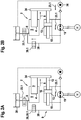
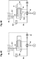
- Figure 2 shows a second embodiment of a hydrostatic linear drive system 1 with a single-acting cylinder 2, which is designed as a plunger cylinder.
- the plunger cylinder comprises a piston rod 3, a first hydraulically active surface 4 and a first cylinder chamber 5 with a first fluid connection 6 for a hydraulic fluid 7.
- the piston rod 3 is also the piston.
- the end face of the piston rod 3 facing the cylinder space 5 is the piston surface and is hydraulically effective.
- the first hydraulically active surface 4 of the single-acting cylinder 2 can be acted upon by the hydraulic fluid 7 in an extension direction 8 via the first fluid connection 6.
- the linear drive system 1 also has a synchronous cylinder 9, which has a piston rod 11, 12 on both sides of the piston 10.
- the annular piston surfaces that surround the piston rods 11, 12 form a second hydraulically active surface 13 and a third hydraulically active surface 14, which are the same in size.
- the synchronous cylinder 9 has a second liquid connection 15 and a third liquid connection 16, the second liquid connection 15 in an annular second Cylinder space 35 on the left side of the piston 10 and the third fluid connection 16 opens into a third annular cylinder space 36 on the right side of the piston 10.
- Hydraulic fluid 7 can be applied to second hydraulically active surface 13 in extension direction 8 via second fluid connection 15.
- the third hydraulically active surface 14 can be acted upon with hydraulic fluid 7 in the retraction direction 17 via the third fluid connection 16.
- a closed hydraulic circuit 18 under a preload pressure comprises the synchronous cylinder 9 and a first hydraulic pump 19 with a first and a second pressure connection 21, 22.
- An electric motor 20 drives the hydraulic pump 19 at constant or variable engine speed.
- the hydraulic pump 19 is preferably an axial piston variable displacement pump in the swashplate design as in the embodiment according to FIG Figure 1 .
- the first pressure connection 21 is connected in a fluid-conducting manner to the second liquid connection 15 and the second pressure connection 22 is connected to the third liquid connection 16 via a hydraulic line 24, 25.
- the bias of the hydraulic fluid in the closed hydraulic circuit 18 can be generated, for example, by a pressure source (not shown) connected to the pressure connections 21, 22.
- the first fluid connection 6 of the single-acting cylinder 2 is connected to the first pressure connection 21 of the first hydraulic pump 19 in a fluid-conducting manner via a hydraulic line 38.
- a second shut-off element 39 is arranged, which is designed as a 2/2-way valve 39.1.
- a high-pressure connection 28 of a second hydraulic pump 26 is connected in a fluid-conducting manner to the second pressure connection 22 of the first hydraulic pump 19 via a hydraulic line 31.
- a check valve 40 in the hydraulic line 31 prevents the hydraulic fluid 7 from flowing back in the direction of the second hydraulic pump 26.
- a low-pressure connection 27 of the second hydraulic pump 26 is connected in a fluid-conducting manner to the expansion tank 30 via a hydraulic line 29.
- the high-pressure connection 28 of the second hydraulic pump 26 is not directly connected to the first fluid connection 6 of the single-acting cylinder 2 in a fluid-conducting manner, but indirectly via the flow path released by the open 2/2-way valve 39.1 and the first hydraulic pump 19 activated in the flow direction 23.1.
- the expansion tank 30, which is open to the environment, receives hydraulic fluid 7 and is also connected in a fluid-conducting manner via a hydraulic line 32 to the first fluid connection 6 of the single-acting cylinder 2.
- a 2/2-way valve 33.1 is arranged as the first shut-off element 33 in the hydraulic line 32 between the expansion tank 30 and the single-acting cylinder 2.
- piston rod 3 of the single-acting cylinder 2 and the piston rod 12 of the synchronous cylinder 9 are mechanically connected to one another by means of a coupling member 34 such that the two cylinders move exclusively synchronously.
- hydraulic fluid 7 When extending the linear drive system 1 in rapid traverse Figure 2A hydraulic fluid 7 is applied to the second hydraulically active surface 13 via the second fluid connection 15 by means of the first hydraulic pump 19 operating in the flow direction 23.1, whereby the piston 10 of the synchronous cylinder 9 moves in the extension direction 8.
- the piston rod 3 of the single-acting cylinder 2 which is connected to the piston rod 12 of the synchronous cylinder 9 via the coupling member 34, is also moved in the extension direction 8 without hydraulic fluid 7 being applied to its hydraulically active surface 4.
- the hydraulic fluid 7 passes through the opened 2/2-way valve 33.1 from the expansion tank 30 via the first fluid connection 6 into the cylinder space 5 of the single-acting cylinder 2 (suction).
- the first hydraulically active surface 4 of the single-acting cylinder 2 is not acted upon because the 2/2-way valve 39.1 in the hydraulic line 38 is closed.
- Hydraulic fluid 7 is applied to the third hydraulically active surface 14 via the third fluid connection 16 by means of the first hydraulic pump 19, which now works in the opposite flow direction 23.2, whereby the piston 10 of the synchronous cylinder 9 moves in the retraction direction 17.
- the via the coupling member 34 with The piston rod 3 of the single-acting cylinder 2 connected to the piston rod 12 of the synchronous cylinder 9 is also moved in the retraction direction 17 without hydraulic fluid 7 acting on its hydraulically active surface 4.
- the hydraulic fluid 7 is displaced from the cylinder space 5 of the single-acting cylinder 2 into the expansion tank 30 through the open 2/2-way valve 33.1.
- the 2/2-way valve 39.1 in the hydraulic line 38 is closed.
- hydraulic fluid 7 When extending the linear drive system 1 in the power gear Figure 2B hydraulic fluid 7 is applied to the first hydraulically active surface 4 of the single-acting cylinder 2 via the first fluid connection 6, as a result of which the single-acting cylinder 2 moves in the extension direction 8.
- the 2/2-way valve 39.1 in the hydraulic line 38 is now open.
- Both the first hydraulic pump 19 and the second hydraulic pump 26 are activated and deliver the hydraulic fluid 7 in the same flow direction 23.1 in the direction of the first fluid connection 6 of the single-acting cylinder 2.
- the activated second hydraulic pump 26 provides the required additional volume of hydraulic fluid 7 from the expansion tank 30 ready to apply hydraulic fluid 7 to the first hydraulically active surface 4 of the single-acting cylinder 2 via the first fluid connection 6 and also to the second hydraulically active surface 13 of the synchronous cylinder 9 via the second fluid connection 15.
- the synchronous cylinder 9 moves synchronously with the single-acting cylinder 2, with which it is coupled via the coupling member 34, in the extension direction 8.
- a flow of the Hydraulic fluid 7 through the hydraulic line 32 into the expansion tank 30 is prevented by the closed 2/2-way valve 33.1.
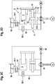
- FIG 3 shows a third embodiment of a hydrostatic linear drive system 1 with a 3-surface cylinder 42, which according to the functions of the single-acting cylinder 2 and the synchronous cylinder 9 of the embodiments Figures 1 and 2 integrated in an assembly.
- Matching components of the 3-surface cylinder 42 are provided with matching reference numerals.
- the 3-surface cylinder 42 has a cylinder tube 43, a cylinder base 44 closing off the cylinder tube 43 on one end face, and a piston rod guide 45 arranged on the opposite end face.
- the piston rod guide 45 guides a piston rod 46 in the axial direction.
- An annular piston 47 is arranged at one end of the piston rod 46.
- a guide pin 48 extends from the cylinder base 44 into the cylinder tube 43.
- the annular piston 47 surrounds the guide pin 48 and is slidable along the Guide pin 48 is guided in an extension direction 8 and a retraction direction 17.
- the piston rod 46 has a cavity 49 in the form of a blind hole which, starting from the central passage in the annular piston 47, extends into the piston rod 46 and surrounds the guide pin 48.
- the 3-surface cylinder has three hydraulically effective surfaces 4, 13, 14.
- the first hydraulically active surface 4 is formed by the first annular piston surface 47.1 facing the cylinder base 44 and delimits a first annular cylinder space 5.
- the second hydraulically active surface 13 is formed by a partial surface 50 of the cavity 49 which lies opposite the end face of the guide pin 48.
- the third hydraulically active surface 14 is formed by the second annular piston surface 47.2 facing the piston rod guide 45.
- a second ring-shaped cylinder space 51 is formed by the ring-shaped piston surface 47.2, the jacket of the piston rod 46, the inner surface of the cylinder tube 43 and, at the end, by the piston rod guide 45.
- the second and third hydraulically active surfaces 13, 14 are the same in size.
- the first cylinder chamber 5 has a first fluid connection 6, via which the first hydraulic connection effective surface 4 in the extension direction 8 of the 3-surface cylinder 42 can be acted upon with a hydraulic fluid 7.
- the second hydraulically active surface 13 can be acted upon by the hydraulic fluid 7 via a second fluid connection 15 in the extension direction 8.
- the second fluid connection 15 is located on the cylinder base 44. From there, the hydraulic fluid 7 passes via a fluid channel 52 to an outlet opening arranged on the end face of the guide pin 48.
- the third hydraulically active surface 14 can be acted upon by the hydraulic fluid 7 in a retraction direction 17 via the third fluid connection 16.
- the third liquid connection 16 opens into the second annular cylinder space 51.
- the first hydraulically active surface 4 can be acted upon by the hydraulic fluid 7 in the extension direction 8 via the first fluid connection 6.
- Hydraulic fluid 7 can be applied to second hydraulically active surface 13 in extension direction 8 via second fluid connection 15.
- the third hydraulically active surface 14 can be acted upon with hydraulic fluid 7 in the retraction direction 17 via the third fluid connection 16.
- a closed hydraulic circuit 18 under a preload pressure comprises the first hydraulic pump 19, the first pressure connection 21 being connected in a fluid-conducting manner to the second liquid connection 15 via the hydraulic line 24 and the second pressure connection 22 via the hydraulic line 25 to the third liquid connection 16.
- An electric motor 20 drives the first hydraulic pump 19 at constant or variable engine speed.
- the hydraulic pump 19 is preferably an axial piston variable displacement pump of the swashplate design. By adjusting the swash plate, the volume flow of the first hydraulic pump can be continuously changed and reversed.
- the prestressing of the hydraulic fluid in the closed hydraulic circuit 18 can be generated, for example, by a pressure vessel (not shown) connected to the pressure connections 21, 22 or by an external hydraulic pump.
- a second hydraulic pump 26 with a low-pressure connection 27 and a high-pressure connection 28 is provided in order to apply hydraulic fluid 7 to the first hydraulically active surface 4 of the 3-surface cylinder 42.
- the low-pressure connection 27 is fluid-conducting via a hydraulic line 29 with an expansion tank 30 and the high-pressure connection 28 is fluid-conducting via a hydraulic line 31 with the first liquid connection 6.
- the compensating tank 30, which is open to the environment, receives hydraulic fluid 7 and is also fluid-conducting via a hydraulic line 32 with the first fluid connection 6 of the 3-surface cylinder 42 connected.
- a 2/2-way valve 33.1 is arranged as the first shut-off element 33 in the hydraulic line 32 between the expansion tank 30 and the first fluid connection 6.
- hydraulic fluid 7 When extending the linear drive system 1 in rapid traverse Figure 3A hydraulic fluid 7 is applied to the second hydraulically active surface 13 via the second fluid connection 15 by means of the first hydraulic pump 19 operating in the flow direction 23.1, whereby the annular piston 47 moves with the piston rod 46 in the extension direction 8.
- the hydraulically active surface 4 is not acted upon by hydraulic fluid 7 in rapid traverse.
- the hydraulic fluid 7 passes through the opened 2/2-way valve 33.1 from the expansion tank 30 via the first fluid connection 6 into the first cylinder space 5 of the 3-surface cylinder 42 (suction).
- the second hydraulic pump 26, which is also connected to the first fluid connection 6, is not active.
- Hydraulic fluid 7 is applied to the third hydraulically active surface 14 via the third fluid connection 16 by means of the first hydraulic pump 19 now operating in the opposite flow direction 23.2, whereby the annular piston 47 moves with the piston rod 46 in the retraction direction 17.
- the hydraulically active surface 4 is not acted upon by hydraulic fluid 7.
- the hydraulic fluid 7 is displaced from the cylinder space 5 of the first cylinder space 5 into the expansion tank 30 through the open 2/2-way valve 33.1.
- the second hydraulic pump 26 connected to the first fluid connection 6 is not active.
- Hydraulic fluid 7 is applied to the first hydraulically active surface 4 of the 3-surface cylinder 42 via the first fluid connection 6 by means of the activated second hydraulic pump 26, whereby the 3-surface cylinder 42 moves in the extension direction 8.
- the first hydraulic pump 19 is also activated in the direction of flow 23.1, so that hydraulic fluid 7 is applied to the second hydraulically active surface 13 via the second fluid connection 15.
- a flow of the hydraulic fluid 7 from the first cylinder space 5 via the hydraulic line 32 into the expansion tank 30 is prevented by the closed 2/2-way valve 33.1.
- the force generated when extending in the power gear is generated by the interaction of the larger, first hydraulically active surface 4 and the smaller, second hydraulically active surface 13.
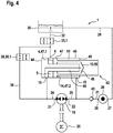
- FIG. 4 shows a fourth embodiment of a hydrostatic linear drive system 1 with a 3-surface cylinder 42, which the functions of the single-acting cylinder 2 and the synchronous cylinder 9 of FIG Embodiments according to Figures 1 and 2 integrated in an assembly.
- the 3-surface cylinder 42 is constructed in accordance with the 3-surface cylinder 42 of the third exemplary embodiment, so that in order to avoid repetition, refer to the explanations of FIG Figure 3 is referred. Differences arise with regard to the hydraulic supply of the 3-surface cylinder 42, which are explained in more detail below. The differences correspond to the differences between the second exemplary embodiment and the first exemplary embodiment.
- the first fluid connection 6 of the 3-surface cylinder 42 is connected in a fluid-conducting manner to the first pressure connection 21 of the first hydraulic pump 19 via a hydraulic line 38.
- a second shut-off element 39 is arranged, which is designed as a 2/2-way valve 39.1.
- a high-pressure connection 28 of a second hydraulic pump 26 is connected in a fluid-conducting manner to the second pressure connection 22 of the first hydraulic pump 19 via a hydraulic line 31.
- a check valve 40 in the hydraulic line 31 prevents the hydraulic fluid 7 from flowing back in the direction of the second hydraulic pump 26.
- the low-pressure connection 27 of the second hydraulic pump 26 is connected to the expansion tank 30 in a fluid-conducting manner via the hydraulic line 29.
- the high-pressure connection 28 of the second hydraulic pump 26 is not directly connected to the first liquid connection 6 of the 3-surface cylinder 42 in a fluid-conducting manner, but rather indirectly via the by the open 2/2-way valve 39.1 and the first hydraulic pump 19 activated in the flow direction 23.1, the flow path is released.
- the expansion tank 30, which is open to the environment, receives hydraulic fluid 7 and is connected in a fluid-conducting manner via a hydraulic line 32 to the first fluid connection 6 of the 3-surface cylinder 42.
- a 2/2-way valve 33.1 is arranged in the hydraulic line 32.
- hydraulic fluid 7 is applied to the second hydraulically active surface 13 via the second fluid connection 15 by means of the first hydraulic pump 19 operating in the flow direction 23.1, whereby the annular piston 47 moves with the piston rod 46 in the extension direction 8.
- the hydraulic fluid 7 passes through the opened 2/2-way valve 33.1 from the expansion tank 30 via the first fluid connection 6 into the cylinder space 5 of the 3-surface cylinder 42 (suction).
- the first hydraulically active surface 4 is not acted upon because the 2/2-way valve 39.1 in the hydraulic line 38 is closed.
- hydraulic fluid 7 When extending the linear drive system 1 in the power gear Figure 4B hydraulic fluid 7 is applied to the first hydraulically active surface 4 via the first fluid connection 6, as a result of which the 3-surface cylinder 42 moves in the extension direction 8.
- the 2/2-way valve 39.1 in the hydraulic line 38 is now open.
- Both the first hydraulic pump 19 and the second hydraulic pump 26 are activated and deliver the hydraulic fluid 7 in the same flow direction 23.1 in the direction of the first fluid connection 6.
- the activated second hydraulic pump 26 provides the required additional volume of hydraulic fluid 7 from the expansion tank 30 in order to transfer over to apply hydraulic fluid 7 to the first fluid connection 6, the first hydraulically active surface 4 of the 3-surface cylinder 42 and, via the second fluid connection 15, also to the second hydraulically active surface 13.
- a flow of the hydraulic fluid 7 via the hydraulic line 32 into the expansion tank 30 is prevented by the closed 2/2-way valve 33.1.
Landscapes
- Engineering & Computer Science (AREA)
- Mechanical Engineering (AREA)
- Physics & Mathematics (AREA)
- Fluid Mechanics (AREA)
- General Engineering & Computer Science (AREA)
- Manufacturing & Machinery (AREA)
- Fluid-Pressure Circuits (AREA)
Applications Claiming Priority (1)
| Application Number | Priority Date | Filing Date | Title |
|---|---|---|---|
| DE102019110917.5A DE102019110917A1 (de) | 2019-04-26 | 2019-04-26 | Hydrostatisches Linear-Antriebssystem |
Publications (3)
| Publication Number | Publication Date |
|---|---|
| EP3734082A1 true EP3734082A1 (fr) | 2020-11-04 |
| EP3734082C0 EP3734082C0 (fr) | 2024-05-15 |
| EP3734082B1 EP3734082B1 (fr) | 2024-05-15 |
Family
ID=69846310
Family Applications (1)
| Application Number | Title | Priority Date | Filing Date |
|---|---|---|---|
| EP20164176.8A Active EP3734082B1 (fr) | 2019-04-26 | 2020-03-19 | Système d'entraînement linéaire hydrostatique |
Country Status (6)
| Country | Link |
|---|---|
| US (1) | US11035391B2 (fr) |
| EP (1) | EP3734082B1 (fr) |
| JP (1) | JP7523933B2 (fr) |
| CN (1) | CN112460083B (fr) |
| DE (1) | DE102019110917A1 (fr) |
| TW (1) | TWI759726B (fr) |
Families Citing this family (4)
| Publication number | Priority date | Publication date | Assignee | Title |
|---|---|---|---|---|
| DE102019126397B4 (de) * | 2019-09-30 | 2023-05-25 | Kautex Maschinenbau Gmbh | Satz von Aktuatoren für eine Schließeinheit, Schließeinheit für eine Blasformmaschine sowie Blasformmaschine mit einer Schließeinheit |
| KR20250166763A (ko) * | 2024-05-21 | 2025-11-28 | 와이프로 엔터프라이시스 피브이티 엘티디. | 중장비 건설 기계를 위한 작동장치 조립체 |
| CN118959377A (zh) * | 2024-08-14 | 2024-11-15 | 太原理工大学 | 一种基于四容腔液压缸的开闭式回路并联驱动系统及控制方法 |
| KR102840550B1 (ko) * | 2024-11-07 | 2025-07-31 | 신상열 | 스프링 리턴식 액추에이터의 유압회로 제어장치 |
Citations (6)
| Publication number | Priority date | Publication date | Assignee | Title |
|---|---|---|---|---|
| JPH0319811A (ja) * | 1989-06-19 | 1991-01-29 | Sumitomo Heavy Ind Ltd | 型締装置 |
| JP2002206507A (ja) * | 2001-01-12 | 2002-07-26 | Mitsubishi Precision Co Ltd | アクチュエータ装置 |
| US20080155975A1 (en) * | 2006-12-28 | 2008-07-03 | Caterpillar Inc. | Hydraulic system with energy recovery |
| DE102010051140A1 (de) | 2010-11-11 | 2012-05-16 | Robert Bosch Gmbh | Ziehpresse sowie mitfahrendes Ziehkissen mit Klemm- und Schnellgangzylinder |
| DE102011078241B3 (de) * | 2011-06-28 | 2012-09-27 | Voith Patent Gmbh | Hydraulikeinheit und Verfahren zum Betreiben einer Hydraulikeinheit |
| DE102016113882A1 (de) | 2016-07-27 | 2018-02-01 | Moog Gmbh | Elektro-hydrostatisches Antriebssystem |
Family Cites Families (5)
| Publication number | Priority date | Publication date | Assignee | Title |
|---|---|---|---|---|
| JPS4830110B1 (fr) * | 1970-08-21 | 1973-09-17 | ||
| JPH0790565B2 (ja) * | 1991-08-06 | 1995-10-04 | 株式会社日本製鋼所 | 樹脂成形プレスのスライド制御方法及びその装置 |
| DE4436666A1 (de) * | 1994-10-13 | 1996-04-18 | Rexroth Mannesmann Gmbh | Hydraulisches Antriebssystem für eine Presse |
| CN103920839B (zh) * | 2014-01-14 | 2016-06-08 | 中南大学 | 大型模锻液压机混合同步平衡控制系统 |
| CN105179343B (zh) * | 2015-10-27 | 2017-03-22 | 中国矿业大学 | 一种多缸同步节能高效液压升降系统及方法 |
-
2019
- 2019-04-26 DE DE102019110917.5A patent/DE102019110917A1/de not_active Ceased
-
2020
- 2020-03-19 EP EP20164176.8A patent/EP3734082B1/fr active Active
- 2020-03-30 JP JP2020060120A patent/JP7523933B2/ja active Active
- 2020-04-24 TW TW109113904A patent/TWI759726B/zh active
- 2020-04-24 US US16/857,938 patent/US11035391B2/en active Active
- 2020-04-24 CN CN202010330900.8A patent/CN112460083B/zh active Active
Patent Citations (6)
| Publication number | Priority date | Publication date | Assignee | Title |
|---|---|---|---|---|
| JPH0319811A (ja) * | 1989-06-19 | 1991-01-29 | Sumitomo Heavy Ind Ltd | 型締装置 |
| JP2002206507A (ja) * | 2001-01-12 | 2002-07-26 | Mitsubishi Precision Co Ltd | アクチュエータ装置 |
| US20080155975A1 (en) * | 2006-12-28 | 2008-07-03 | Caterpillar Inc. | Hydraulic system with energy recovery |
| DE102010051140A1 (de) | 2010-11-11 | 2012-05-16 | Robert Bosch Gmbh | Ziehpresse sowie mitfahrendes Ziehkissen mit Klemm- und Schnellgangzylinder |
| DE102011078241B3 (de) * | 2011-06-28 | 2012-09-27 | Voith Patent Gmbh | Hydraulikeinheit und Verfahren zum Betreiben einer Hydraulikeinheit |
| DE102016113882A1 (de) | 2016-07-27 | 2018-02-01 | Moog Gmbh | Elektro-hydrostatisches Antriebssystem |
Also Published As
| Publication number | Publication date |
|---|---|
| CN112460083A (zh) | 2021-03-09 |
| TWI759726B (zh) | 2022-04-01 |
| JP7523933B2 (ja) | 2024-07-29 |
| EP3734082C0 (fr) | 2024-05-15 |
| DE102019110917A1 (de) | 2020-10-29 |
| EP3734082B1 (fr) | 2024-05-15 |
| US11035391B2 (en) | 2021-06-15 |
| CN112460083B (zh) | 2024-07-26 |
| US20200340503A1 (en) | 2020-10-29 |
| TW202104758A (zh) | 2021-02-01 |
| JP2020183806A (ja) | 2020-11-12 |
Similar Documents
| Publication | Publication Date | Title |
|---|---|---|
| EP3734082B1 (fr) | Système d'entraînement linéaire hydrostatique | |
| EP2480405B1 (fr) | Entrainement hydraulique precontraint dote d'une pompe a vitesse variable | |
| AT509239B1 (de) | Antriebsvorrichtung für eine biegepresse | |
| EP2722165B1 (fr) | Circuit hydraulique pour un axe hydraulique et axe hydraulique | |
| DE68917717T2 (de) | Hydropneumatische Zylindervorrichtung. | |
| DE102012016838B4 (de) | Hydraulische Steuerschaltung für eine hydraulisch betätigte Gießeinheit | |
| EP2294331B1 (fr) | Dispositif de vanne hydraulique | |
| EP1423614B1 (fr) | Transmetteur de pression | |
| DE102020201216B4 (de) | Hydraulische Gießeinheit | |
| EP3491253A1 (fr) | Système d'entraînement électro-hydrostatique | |
| EP2243991A1 (fr) | Soupape et dispositif de commande hydraulique | |
| EP3880975B1 (fr) | Système d'actionneur électrohydrostatique | |
| DE9405764U1 (de) | Pressengetriebenes Werkzeugmodul, insbesondere eine pressengetriebene Querstanz- oder Biegeeinheit | |
| DE3811312A1 (de) | Doppeltwirkender arbeitszylinder | |
| DE102018222425A1 (de) | Hydrostatischer Antrieb, insbesondere für eine Presse oder eine Spritzgießmaschine | |
| EP2229537B1 (fr) | Dispositif d'entraînement hydraulique à deux chambres de pression, et procédé permettant de faire fonctionner un dispositif d'entraînement hydraulique à deux chambres de pression | |
| DE10339004B4 (de) | Hydraulische Presse | |
| EP4159373B1 (fr) | Système de serrage doté d'une course rapide et force et procédé de fonctionnement d'un système de serrage | |
| DE102009048763B4 (de) | Anordnung zur Druckversorgung eines mit einer druckmittelbetätigten Kolben-Zylinder-Einheit mitbewegten Verbrauchers | |
| EP0559651B1 (fr) | Machine a entrainement hydraulique avec deux cylindres d'entrainement | |
| DE10000109B4 (de) | Nullstellungseinrichtung für eine hydrostatische Kolben-Zylinder-Einheit | |
| EP2600011A2 (fr) | Distributeur hydraulique pour le dispositif de levage d'un véhicule agricole | |
| DE3640640C2 (de) | Hydrostatisches Antriebssystem mit einem Verbraucher mit zwei Anschlüssen | |
| DE102005047823A1 (de) | Eilgangzylindereinheit | |
| DE102009011441B4 (de) | Hydraulikantrieb |
Legal Events
| Date | Code | Title | Description |
|---|---|---|---|
| PUAI | Public reference made under article 153(3) epc to a published international application that has entered the european phase |
Free format text: ORIGINAL CODE: 0009012 |
|
| STAA | Information on the status of an ep patent application or granted ep patent |
Free format text: STATUS: THE APPLICATION HAS BEEN PUBLISHED |
|
| AK | Designated contracting states |
Kind code of ref document: A1 Designated state(s): AL AT BE BG CH CY CZ DE DK EE ES FI FR GB GR HR HU IE IS IT LI LT LU LV MC MK MT NL NO PL PT RO RS SE SI SK SM TR |
|
| AX | Request for extension of the european patent |
Extension state: BA ME |
|
| STAA | Information on the status of an ep patent application or granted ep patent |
Free format text: STATUS: REQUEST FOR EXAMINATION WAS MADE |
|
| 17P | Request for examination filed |
Effective date: 20210429 |
|
| RBV | Designated contracting states (corrected) |
Designated state(s): AL AT BE BG CH CY CZ DE DK EE ES FI FR GB GR HR HU IE IS IT LI LT LU LV MC MK MT NL NO PL PT RO RS SE SI SK SM TR |
|
| STAA | Information on the status of an ep patent application or granted ep patent |
Free format text: STATUS: EXAMINATION IS IN PROGRESS |
|
| 17Q | First examination report despatched |
Effective date: 20221214 |
|
| GRAP | Despatch of communication of intention to grant a patent |
Free format text: ORIGINAL CODE: EPIDOSNIGR1 |
|
| STAA | Information on the status of an ep patent application or granted ep patent |
Free format text: STATUS: GRANT OF PATENT IS INTENDED |
|
| INTG | Intention to grant announced |
Effective date: 20231215 |
|
| GRAS | Grant fee paid |
Free format text: ORIGINAL CODE: EPIDOSNIGR3 |
|
| GRAA | (expected) grant |
Free format text: ORIGINAL CODE: 0009210 |
|
| STAA | Information on the status of an ep patent application or granted ep patent |
Free format text: STATUS: THE PATENT HAS BEEN GRANTED |
|
| AK | Designated contracting states |
Kind code of ref document: B1 Designated state(s): AL AT BE BG CH CY CZ DE DK EE ES FI FR GB GR HR HU IE IS IT LI LT LU LV MC MK MT NL NO PL PT RO RS SE SI SK SM TR |
|
| REG | Reference to a national code |
Ref country code: CH Ref legal event code: EP |
|
| REG | Reference to a national code |
Ref country code: DE Ref legal event code: R096 Ref document number: 502020007978 Country of ref document: DE |
|
| REG | Reference to a national code |
Ref country code: IE Ref legal event code: FG4D Free format text: LANGUAGE OF EP DOCUMENT: GERMAN |
|
| U01 | Request for unitary effect filed |
Effective date: 20240611 |
|
| U07 | Unitary effect registered |
Designated state(s): AT BE BG DE DK EE FI FR IT LT LU LV MT NL PT SE SI Effective date: 20240620 |
|
| RAP2 | Party data changed (patent owner data changed or rights of a patent transferred) |
Owner name: KAUTEX MASCHINENBAU SYSTEM GMBH |
|
| U1K | Transfer of rights of the unitary patent after the registration of the unitary effect |
Owner name: KAUTEX MASCHINENBAU SYSTEM GMBH; DE |
|
| PG25 | Lapsed in a contracting state [announced via postgrant information from national office to epo] |
Ref country code: IS Free format text: LAPSE BECAUSE OF FAILURE TO SUBMIT A TRANSLATION OF THE DESCRIPTION OR TO PAY THE FEE WITHIN THE PRESCRIBED TIME-LIMIT Effective date: 20240915 |
|
| PG25 | Lapsed in a contracting state [announced via postgrant information from national office to epo] |
Ref country code: HR Free format text: LAPSE BECAUSE OF FAILURE TO SUBMIT A TRANSLATION OF THE DESCRIPTION OR TO PAY THE FEE WITHIN THE PRESCRIBED TIME-LIMIT Effective date: 20240515 |
|
| PG25 | Lapsed in a contracting state [announced via postgrant information from national office to epo] |
Ref country code: GR Free format text: LAPSE BECAUSE OF FAILURE TO SUBMIT A TRANSLATION OF THE DESCRIPTION OR TO PAY THE FEE WITHIN THE PRESCRIBED TIME-LIMIT Effective date: 20240816 |
|
| PG25 | Lapsed in a contracting state [announced via postgrant information from national office to epo] |
Ref country code: ES Free format text: LAPSE BECAUSE OF FAILURE TO SUBMIT A TRANSLATION OF THE DESCRIPTION OR TO PAY THE FEE WITHIN THE PRESCRIBED TIME-LIMIT Effective date: 20240515 |
|
| PG25 | Lapsed in a contracting state [announced via postgrant information from national office to epo] |
Ref country code: PL Free format text: LAPSE BECAUSE OF FAILURE TO SUBMIT A TRANSLATION OF THE DESCRIPTION OR TO PAY THE FEE WITHIN THE PRESCRIBED TIME-LIMIT Effective date: 20240515 |
|
| PG25 | Lapsed in a contracting state [announced via postgrant information from national office to epo] |
Ref country code: PL Free format text: LAPSE BECAUSE OF FAILURE TO SUBMIT A TRANSLATION OF THE DESCRIPTION OR TO PAY THE FEE WITHIN THE PRESCRIBED TIME-LIMIT Effective date: 20240515 Ref country code: NO Free format text: LAPSE BECAUSE OF FAILURE TO SUBMIT A TRANSLATION OF THE DESCRIPTION OR TO PAY THE FEE WITHIN THE PRESCRIBED TIME-LIMIT Effective date: 20240815 Ref country code: IS Free format text: LAPSE BECAUSE OF FAILURE TO SUBMIT A TRANSLATION OF THE DESCRIPTION OR TO PAY THE FEE WITHIN THE PRESCRIBED TIME-LIMIT Effective date: 20240915 Ref country code: HR Free format text: LAPSE BECAUSE OF FAILURE TO SUBMIT A TRANSLATION OF THE DESCRIPTION OR TO PAY THE FEE WITHIN THE PRESCRIBED TIME-LIMIT Effective date: 20240515 Ref country code: GR Free format text: LAPSE BECAUSE OF FAILURE TO SUBMIT A TRANSLATION OF THE DESCRIPTION OR TO PAY THE FEE WITHIN THE PRESCRIBED TIME-LIMIT Effective date: 20240816 Ref country code: ES Free format text: LAPSE BECAUSE OF FAILURE TO SUBMIT A TRANSLATION OF THE DESCRIPTION OR TO PAY THE FEE WITHIN THE PRESCRIBED TIME-LIMIT Effective date: 20240515 Ref country code: RS Free format text: LAPSE BECAUSE OF FAILURE TO SUBMIT A TRANSLATION OF THE DESCRIPTION OR TO PAY THE FEE WITHIN THE PRESCRIBED TIME-LIMIT Effective date: 20240815 |
|
| PG25 | Lapsed in a contracting state [announced via postgrant information from national office to epo] |
Ref country code: CZ Free format text: LAPSE BECAUSE OF FAILURE TO SUBMIT A TRANSLATION OF THE DESCRIPTION OR TO PAY THE FEE WITHIN THE PRESCRIBED TIME-LIMIT Effective date: 20240515 |
|
| PG25 | Lapsed in a contracting state [announced via postgrant information from national office to epo] |
Ref country code: SK Free format text: LAPSE BECAUSE OF FAILURE TO SUBMIT A TRANSLATION OF THE DESCRIPTION OR TO PAY THE FEE WITHIN THE PRESCRIBED TIME-LIMIT Effective date: 20240515 Ref country code: RO Free format text: LAPSE BECAUSE OF FAILURE TO SUBMIT A TRANSLATION OF THE DESCRIPTION OR TO PAY THE FEE WITHIN THE PRESCRIBED TIME-LIMIT Effective date: 20240515 |
|
| PG25 | Lapsed in a contracting state [announced via postgrant information from national office to epo] |
Ref country code: SM Free format text: LAPSE BECAUSE OF FAILURE TO SUBMIT A TRANSLATION OF THE DESCRIPTION OR TO PAY THE FEE WITHIN THE PRESCRIBED TIME-LIMIT Effective date: 20240515 |
|
| PG25 | Lapsed in a contracting state [announced via postgrant information from national office to epo] |
Ref country code: SM Free format text: LAPSE BECAUSE OF FAILURE TO SUBMIT A TRANSLATION OF THE DESCRIPTION OR TO PAY THE FEE WITHIN THE PRESCRIBED TIME-LIMIT Effective date: 20240515 Ref country code: SK Free format text: LAPSE BECAUSE OF FAILURE TO SUBMIT A TRANSLATION OF THE DESCRIPTION OR TO PAY THE FEE WITHIN THE PRESCRIBED TIME-LIMIT Effective date: 20240515 Ref country code: RO Free format text: LAPSE BECAUSE OF FAILURE TO SUBMIT A TRANSLATION OF THE DESCRIPTION OR TO PAY THE FEE WITHIN THE PRESCRIBED TIME-LIMIT Effective date: 20240515 Ref country code: CZ Free format text: LAPSE BECAUSE OF FAILURE TO SUBMIT A TRANSLATION OF THE DESCRIPTION OR TO PAY THE FEE WITHIN THE PRESCRIBED TIME-LIMIT Effective date: 20240515 |
|
| REG | Reference to a national code |
Ref country code: DE Ref legal event code: R097 Ref document number: 502020007978 Country of ref document: DE |
|
| PLBE | No opposition filed within time limit |
Free format text: ORIGINAL CODE: 0009261 |
|
| STAA | Information on the status of an ep patent application or granted ep patent |
Free format text: STATUS: NO OPPOSITION FILED WITHIN TIME LIMIT |
|
| 26N | No opposition filed |
Effective date: 20250218 |
|
| U20 | Renewal fee for the european patent with unitary effect paid |
Year of fee payment: 6 Effective date: 20250325 |
|
| PG25 | Lapsed in a contracting state [announced via postgrant information from national office to epo] |
Ref country code: MC Free format text: LAPSE BECAUSE OF FAILURE TO SUBMIT A TRANSLATION OF THE DESCRIPTION OR TO PAY THE FEE WITHIN THE PRESCRIBED TIME-LIMIT Effective date: 20240515 |
|
| REG | Reference to a national code |
Ref country code: CH Ref legal event code: H13 Free format text: ST27 STATUS EVENT CODE: U-0-0-H10-H13 (AS PROVIDED BY THE NATIONAL OFFICE) Effective date: 20251023 |
|
| GBPC | Gb: european patent ceased through non-payment of renewal fee |
Effective date: 20250319 |
|
| PG25 | Lapsed in a contracting state [announced via postgrant information from national office to epo] |
Ref country code: GB Free format text: LAPSE BECAUSE OF NON-PAYMENT OF DUE FEES Effective date: 20250319 |
|
| PG25 | Lapsed in a contracting state [announced via postgrant information from national office to epo] |
Ref country code: CH Free format text: LAPSE BECAUSE OF NON-PAYMENT OF DUE FEES Effective date: 20250331 |
|
| PG25 | Lapsed in a contracting state [announced via postgrant information from national office to epo] |
Ref country code: IE Free format text: LAPSE BECAUSE OF NON-PAYMENT OF DUE FEES Effective date: 20250319 |