EP3734130A1 - Dichtungsfuge und klemmvorrichtung sowie -einheit, die eine solche dichtungsfuge umfasst - Google Patents
Dichtungsfuge und klemmvorrichtung sowie -einheit, die eine solche dichtungsfuge umfasst Download PDFInfo
- Publication number
- EP3734130A1 EP3734130A1 EP20171694.1A EP20171694A EP3734130A1 EP 3734130 A1 EP3734130 A1 EP 3734130A1 EP 20171694 A EP20171694 A EP 20171694A EP 3734130 A1 EP3734130 A1 EP 3734130A1
- Authority
- EP
- European Patent Office
- Prior art keywords
- seal
- sleeve
- tube
- belt
- collar
- Prior art date
- Legal status (The legal status is an assumption and is not a legal conclusion. Google has not performed a legal analysis and makes no representation as to the accuracy of the status listed.)
- Granted
Links
Images



Classifications
-
- F—MECHANICAL ENGINEERING; LIGHTING; HEATING; WEAPONS; BLASTING
- F16—ENGINEERING ELEMENTS AND UNITS; GENERAL MEASURES FOR PRODUCING AND MAINTAINING EFFECTIVE FUNCTIONING OF MACHINES OR INSTALLATIONS; THERMAL INSULATION IN GENERAL
- F16L—PIPES; JOINTS OR FITTINGS FOR PIPES; SUPPORTS FOR PIPES, CABLES OR PROTECTIVE TUBING; MEANS FOR THERMAL INSULATION IN GENERAL
- F16L21/00—Joints with sleeve or socket
-
- F—MECHANICAL ENGINEERING; LIGHTING; HEATING; WEAPONS; BLASTING
- F16—ENGINEERING ELEMENTS AND UNITS; GENERAL MEASURES FOR PRODUCING AND MAINTAINING EFFECTIVE FUNCTIONING OF MACHINES OR INSTALLATIONS; THERMAL INSULATION IN GENERAL
- F16L—PIPES; JOINTS OR FITTINGS FOR PIPES; SUPPORTS FOR PIPES, CABLES OR PROTECTIVE TUBING; MEANS FOR THERMAL INSULATION IN GENERAL
- F16L21/00—Joints with sleeve or socket
- F16L21/06—Joints with sleeve or socket with a divided sleeve or ring clamping around the pipe ends
- F16L21/065—Joints with sleeve or socket with a divided sleeve or ring clamping around the pipe ends tightened by tangentially-arranged threaded pins
-
- F—MECHANICAL ENGINEERING; LIGHTING; HEATING; WEAPONS; BLASTING
- F16—ENGINEERING ELEMENTS AND UNITS; GENERAL MEASURES FOR PRODUCING AND MAINTAINING EFFECTIVE FUNCTIONING OF MACHINES OR INSTALLATIONS; THERMAL INSULATION IN GENERAL
- F16L—PIPES; JOINTS OR FITTINGS FOR PIPES; SUPPORTS FOR PIPES, CABLES OR PROTECTIVE TUBING; MEANS FOR THERMAL INSULATION IN GENERAL
- F16L23/00—Flanged joints
- F16L23/003—Auxiliary devices
-
- F—MECHANICAL ENGINEERING; LIGHTING; HEATING; WEAPONS; BLASTING
- F16—ENGINEERING ELEMENTS AND UNITS; GENERAL MEASURES FOR PRODUCING AND MAINTAINING EFFECTIVE FUNCTIONING OF MACHINES OR INSTALLATIONS; THERMAL INSULATION IN GENERAL
- F16L—PIPES; JOINTS OR FITTINGS FOR PIPES; SUPPORTS FOR PIPES, CABLES OR PROTECTIVE TUBING; MEANS FOR THERMAL INSULATION IN GENERAL
- F16L21/00—Joints with sleeve or socket
- F16L21/002—Sleeves or nipples for pipes of the same diameter; Reduction pieces
- F16L21/005—Sleeves or nipples for pipes of the same diameter; Reduction pieces made of elastic material, e.g. partly or completely surrounded by clamping devices
-
- F—MECHANICAL ENGINEERING; LIGHTING; HEATING; WEAPONS; BLASTING
- F16—ENGINEERING ELEMENTS AND UNITS; GENERAL MEASURES FOR PRODUCING AND MAINTAINING EFFECTIVE FUNCTIONING OF MACHINES OR INSTALLATIONS; THERMAL INSULATION IN GENERAL
- F16L—PIPES; JOINTS OR FITTINGS FOR PIPES; SUPPORTS FOR PIPES, CABLES OR PROTECTIVE TUBING; MEANS FOR THERMAL INSULATION IN GENERAL
- F16L21/00—Joints with sleeve or socket
- F16L21/02—Joints with sleeve or socket with elastic sealing rings between pipe and sleeve or between pipe and socket, e.g. with rolling or other prefabricated profiled rings
- F16L21/03—Joints with sleeve or socket with elastic sealing rings between pipe and sleeve or between pipe and socket, e.g. with rolling or other prefabricated profiled rings placed in the socket before connection
-
- F—MECHANICAL ENGINEERING; LIGHTING; HEATING; WEAPONS; BLASTING
- F16—ENGINEERING ELEMENTS AND UNITS; GENERAL MEASURES FOR PRODUCING AND MAINTAINING EFFECTIVE FUNCTIONING OF MACHINES OR INSTALLATIONS; THERMAL INSULATION IN GENERAL
- F16L—PIPES; JOINTS OR FITTINGS FOR PIPES; SUPPORTS FOR PIPES, CABLES OR PROTECTIVE TUBING; MEANS FOR THERMAL INSULATION IN GENERAL
- F16L23/00—Flanged joints
- F16L23/04—Flanged joints the flanges being connected by members tensioned in the radial plane
- F16L23/08—Flanged joints the flanges being connected by members tensioned in the radial plane connection by tangentially arranged pin and nut
-
- F—MECHANICAL ENGINEERING; LIGHTING; HEATING; WEAPONS; BLASTING
- F16—ENGINEERING ELEMENTS AND UNITS; GENERAL MEASURES FOR PRODUCING AND MAINTAINING EFFECTIVE FUNCTIONING OF MACHINES OR INSTALLATIONS; THERMAL INSULATION IN GENERAL
- F16L—PIPES; JOINTS OR FITTINGS FOR PIPES; SUPPORTS FOR PIPES, CABLES OR PROTECTIVE TUBING; MEANS FOR THERMAL INSULATION IN GENERAL
- F16L23/00—Flanged joints
- F16L23/16—Flanged joints characterised by the sealing means
- F16L23/18—Flanged joints characterised by the sealing means the sealing means being rings
Definitions
- the present disclosure relates to a seal, as well as to a clamping device and to a clamping assembly comprising such a seal.
- Annular seals are known, produced by a closed ring. To achieve their sealing function, these seals must be compressed and must therefore be formed from materials allowing such compression while having the qualities required to withstand the conditions of the environment in which the seal is placed. tightness, for example in terms of temperature, pressure, or variation of these parameters. In addition, generally, for such closed seals, the difference between the diameter of the seal in the free state and the diameter of the seal in the clamped state, after compression, is generally small. . Thus, these closed type gaskets are not suitable for some applications.
- tightening devices comprising a collar which has a belt capable of being tightened by reducing its diameter and a seal pre-mounted in the collar. More precisely, this system comprises a washer which comprises a closed annular part forming the seal and tabs connecting this seal to the collar. The closed annular seal is initially maintained at a significant distance from the inner periphery of the collar so as to allow engagement of the outer tube between the seal and this inner periphery. Then, the inner tube is itself engaged so as to come into contact with the seal.
- This device is particularly suitable for clamping two tubes fitted together and having flared radially projecting surfaces serving as a support for a clamp which comprises a recess capable of accommodating these flared radially projecting surfaces, the closed annular seal itself having a frustoconical shape adapted to these flared surfaces.
- Open type seals are also known, in particular of the type produced by a strip wound on itself and the ends of which cooperate with one another by a sealing arrangement.
- a seal is for example disclosed by document EP 1 181 477 .
- a seal of this type has the advantage of being easy to manufacture and in particular of making it possible, without very significant change in the manufacturing tool, to manufacture seals of different diameters, since the diameter of the seal sealing depends on the length of the strip in which it is formed.
- a seal of this type can be easily mounted around or inside objects to which it must ensure a sealed connection and can be made of a material which is not necessarily required to deform. notably under radial compression, which makes it possible to choose materials resistant to demanding environmental stresses, for example in terms of temperature, pressure or gradient of these parameters.
- such a seal can be made from a metal of the stainless steel type.
- the opening of the seal that is to say the junction between the ends of the strip in which it is formed, may present a zone of weakness in terms of sealing, despite the fact that the the ends in question cooperate with each other by a sealing arrangement.
- the seal may have a spring effect, i.e. the strip in which it is formed may have a tendency to unroll which, in certain applications, can complicate handling, storage and assembly.
- the disclosure aims to remedy at least substantially the aforementioned drawbacks.
- the disclosure relates to a seal comprising a first and a second coaxial sleeve arranged around each other while being retained with respect to each other, each sleeve being formed by a strip wound on itself, the ends of which are configured to cooperate with each other via a sealing arrangement allowing a reduction in the diameter of the sleeve, the sealing arrangements of the two sleeves being angularly offset.
- each sleeve Due to the angular offset of the sealing arrangements of the two sleeves, the sealing arrangement of each sleeve is "bridged" by the other sleeve.
- the sealing arrangement of each sleeve is radially covered, either on the outside or on the inside, by the strip in which the other sleeve is formed.
- the sleeves are retained with respect to each other, which means that they hold each other. In other words, the presence of each sleeve tends to prevent the other sleeve from tending to unwind or not to retain its desired shape.
- the gasket retains the advantage of open type gaskets in that it is simple to manufacture for different diameters by adjusting the length of the bands in which the two sleeves are formed and in that it performs its sealing function by reducing its diameter bringing the respective ends of the two sleeves closer together.
- the two sleeves are formed from different materials, the strip forming the first sleeve being optionally formed from a mica-based material and the strip forming the second sleeve being optionally metallic.
- the strip forming at least one of the first and second sleeves naturally tends to unwind and is kept rolled up by the other sleeve.
- the sealing arrangement of at least one of the first and second sleeves comprises a male / female engagement conformation.
- At least one of the first and second sleeves has at least one wedging tab, under which one edge of the other sleeve is wedged.
- the present disclosure also relates to a tightening device comprising a collar which has a belt capable of being tightened by reducing its diameter, and a seal according to the present disclosure, in which the seal is disposed inside. of the belt by being retained axially relative to the collar and by being configured to release an annular space allowing the insertion of an annular object between the seal and the belt.
- this clamping device makes it possible to use a seal functioning as an open type seal pre-mounted in a collar.
- the annular space allows the insertion of an annular object such as the end of a tube between the belt and the seal.
- the clamping device is pre-mounted on this annular object, which can receive another annular object, in particular an inner tube which will be fitted in this assembly, in particular by being fitted in the seal so that this seal is located between the two objects fitted into one another to ensure their tight connection once the collar is tightened around the fitting thus produced.
- one of the elements comprising the collar and the seal comprises at least one spacer providing the annular space between the seal and the belt, the spacer optionally comprising a spacer lug carried by the seal. sealing, projecting radially outwards.
- the device comprises an angular seal keying device configured to determine an angular position of the seal relative to the collar.
- one of the elements formed by the belt and the seal has a wedging edge and the other element has a wedging projection adapted to cooperate with the wedging edge to retain the seal vis-à-vis. -vis of a displacement relative to the collar.
- the seal has a front edge provided with at least one stopper configured to cooperate with the front edge of the belt to retain the seal against movement in at least one direction by. relative to the belt, the stop optionally comprising a tab which is straightened outwards.
- the belt has a window, the edge of which forms a wedging edge, and the seal has a retaining tab straightened in this window.
- the collar has tightening tabs, raised radially relative to the belt and able to be moved relative to one another to tighten the collar.
- the present disclosure also relates to a tube clamping assembly, comprising a clamping device according to the present disclosure and a tube whose end is adapted to be inserted between the seal and the belt.
- the assembly comprises a tube position key determining an angular position of the tube relative to at least one of the elements comprising the seal and the collar.
- the seal has a tube position keying tab which projects radially outwardly from the seal and which is configured to engage in a slot formed at the end of the tube.
- the seal comprises an anti-extraction tab, configured to cooperate with a window of the tube to oppose the extraction of the seal from the tube.
- the set represented on the figure 1 comprises a clamping device which itself comprises a collar 10 and a seal 20, which comprises a first sleeve 30 and a second sleeve 40.
- This assembly also comprises an outer tube 1 and an inner tube 2.
- the inner tube 2 is configured to be fitted into the outer tube 1 to connect the two tubes. More precisely, the outer tube 2 fits into the end 1A of the outer tube 1 around which the clamp is placed in order to tighten the assembly thus produced.
- the seal 20 is itself arranged between the inner and outer tubes. For the fitting, the seal 20 is placed in the end 1A of the tube 1 around which the clamp 10 is arranged, and the inner tube 2 fits into the seal 20.
- the parts of the two tubes 1 and 2 fitted one inside the other form cylindrical surfaces without bulging.
- the end 1A of the outer tube 1 is however delimited, on the side opposite to its free end 1'A, by a shoulder 1 "A.
- the end 1A is thus widened, and the remaining part 1B of the tube 1 has a similar diameter. to that of tube 2.
- each of the first and second sleeves 30 and 40 is formed by a strip, respectively 32 and 42, which is wound on itself and the ends of which are configured to cooperate with each other via an arrangement sealing.
- this sealing arrangement 34 which in this case comprises a male / female engagement.
- this sealing arrangement comprises a notch 34A formed at the end 32A and delimited between contact edges 34'A formed in the species by internal edges of tabs 35A remaining on either side of the notch 34A.
- the sealing arrangement 34 also includes a tab 34B formed at the end 32B. It can be seen that, over part of the length of the notch, this length being measured circumferentially, the width of this notch (measured parallel to the axis A) varies. More precisely, in the part of the notch close to the free ends of the tabs 35A, the width of the notch increases as one gets closer to these free ends, that is to say as the we move away from the bottom of the notch. Likewise, in a part of the length of the tongue 34B, the width of this tongue increases as one moves away from its free end.
- the contact pressure between the edges of the tongue and the contact edges 34'A increases so as to achieve waterproof contact.
- the end part of the tongue and the bottom part of the notch have a constant and equal width, which facilitates the advancement of the tongue into the notch.
- the second sleeve 40 is formed from a strip 42 wound on itself and the ends of which, respectively 42A and 42B, cooperate with each other by a sealing arrangement 44.
- this sealing arrangement 44 comprises a male / female engagement conformation.
- the end 42A comprises a notch 44A delimited between two tabs 45A
- the end 42B comprises a tongue 44B which, when the diameter of the sleeve 40 decreases, enters the notch 44A.
- this tongue is delimited laterally by two slots 45B into which the tabs 45A penetrate as the tongue 44B enters the notch 44A.
- These slots 45B are themselves bordered laterally by tabs 45C.
- the sealing arrangement forms a sort of baffle considered axially, the contact zone between the ends 42A and 42B being effected between the tabs 45C and 45A and the tongue 44B.
- the sealing arrangement 44 of the sleeve 40 could have the geometry described above for the sealing arrangement 34 of the sleeve 30 and vice versa.
- Other sealing arrangements can be provided, whether either as in this case provided directly on the strip 32 or 42, in one piece with it, or else added, for example in a more deformable material. Sealing can also be obtained by a baffle effect without necessarily implementing the contact stresses mentioned above.
- the tightness can be linked to the contact constraints mentioned above, in particular within a male / female engagement, these constraints being able to go as far as causing deformations. , plastic or elastic.
- the sleeves 30 and 40 are assembled around each other to form the seal 20, their respective sealing arrangements 34 and 44 are angularly offset.
- the junction zones between the ends 32A and 32B of the strip in which the sleeve 30 is formed are covered radially by a solid portion of the strip 42 in which the sleeve 40 is formed.
- the junction of the ends 42A and 42B of the strip 42 in which the sleeve 40 is formed is radially covered by a solid part of the strip 32 in which the sleeve 30 is formed.
- the sleeve 30 is disposed around the sleeve 40, so that the arrangement of The seal 34 is covered radially on the inner side and the sealing arrangement 44 is covered radially on the outer side.
- the elements facing the axis A of the seal (which corresponds to the axis A of the belt of the collar and of the tubes when these elements are assembled) will be qualified as “internal”, while the external elements are those which are opposed to this axis.
- the qualifiers “front” and “rear” are understood in relation to the direction of fitting of the tubes.
- the end 1'A of the tube 1 is its front end from which it is fitted onto the tube 2.
- the front edges 31A and 41A of the sleeves 30 and 40 are those which, when the seal is arranged around the end 1A of the tube 1 are closest to the free end 1'A of this tube, as opposed to the rear edges 31B and 41B of these sleeves.
- one of the sleeves may naturally tend to unwind to provide an elastic effect. This may be the case when the sleeve in question is made of metal, as is for example the case of the second sleeve 40, and can also be the case of a sleeve made of a mica-based material, as is for example the case of the sleeve 30.
- the fact that the two sleeves are retained relative to each other limits this tendency.
- the second sleeve 40 in particular because of the bridging that it operates in the region of the junction between the ends 32A and 32B of the first sleeve 30, tends to oppose the separation of these ends 32A and 32B and therefore the unwinding of the strip 32 in which this first sleeve 30 is formed.
- the two sleeves can be retained with respect to each other by wedging. Even if the two sleeves each have a certain elasticity giving them a tendency to unwind, the jamming stresses (or, generally, the stresses due to the fact that they are retained with respect to each other) may be sufficient. for, by bridging the junction of the ends of each sleeve by the other sleeve, to oppose this unwinding.
- the wedging which can be achieved in the form of a pinch, has the advantage of achieving the desired retention while allowing slight movements of the two sleeves relative to each other, in their circumferential directions, in order to allow the ends of the bands 32 and 42 to be brought together allowing the diameter of the seal to be reduced under the effect of the clamping of the collar.
- the two sleeves are retained relative to each other by wedging.
- at least one of the first and second sleeves 30 and 40 has at least one jamming tab 46, under which an edge of the other sleeve, in particular an edge perpendicular to the axis A of the sleeve, is stuck.
- the second sleeve 40 has wedging tabs 46 under which the edges of the first sleeve 30 are wedged.
- the clamping tabs 46 are provided on the front 41A and rear 41B edges of the sleeve 40, so as to be able to clamp the front and rear edges 31A and 31B of the sleeve 30.
- wedging tabs are formed by folded extensions on the side of the outer face of the sleeve 40.
- these wedging tabs can initially be straightened radially, then, once the sleeve 30 is placed around the sleeve 40, be folded against the outer face of this sleeve to come pinching the edges of the sleeve 30.
- a tab 49 ' is longer than the wedging tabs 46 which have just been described.
- This tab 49 ' in addition to an anti-extraction and tube polarizing function which will be described later, performs a jamming function. Because of its length, it wedges not only the edge of the sleeve 30, but also a tab 35A (that which is close to the rear edge of the sleeve 30) and the adjacent edge of the tongue 34B of this sleeve.
- a tab 49 which, as will be seen below, performs both a wedging function and a tube polarizing function, wedges the other tab 35A and the edge of the tab 34B which is adjacent to this other tab.
- the free end of the tongue 34B is itself wedged under tabs 46 'cut from the strip 42 and slightly straightened.
- the jamming tabs 46, 49 and 49 ' are distributed over each of the front and rear edges of the sleeve 40.
- the jamming tabs 46, 49 and 49 ' are distributed over each of the front and rear edges of the sleeve 40.
- between three and fifteen jamming tabs can be provided, for example between four and ten jamming tabs. on one and / or the other of the front and rear edges.
- the number of wedging tabs may depend on the diameter of the sleeve.
- wedging tabs are made in the internal sleeve and folded outwards, so that the internal periphery of the seal is smooth.
- the clamping device comprises a clamp 10 and the seal which has just been described.
- the collar 10 comprises a belt 12 which is able to be tightened by reducing its diameter.
- This belt 12 defines a cylindrical shape coaxial with the sleeves 30 and 40 of the seal 20, when the seal is arranged in the collar and tightened around the tubes.
- annular space 50 is released between the outer periphery of the seal 20 (in this case the outer periphery of the sleeve 30) and the inner periphery belt 12. As can be seen from the figure 1 , this allows the end 1A of the tube 1 to be inserted into this annular space.
- the annular space 50 can be provided by means of a spacer which extends between the seal and the belt.
- this spacer comprises at least one spacer tab 47 which is carried by the seal 20 and which projects radially outwards. More specifically, in this case, the spacer tab 47 is carried by the sleeve 40 and, like the wedging tabs 46, 49 and 49 ', it is produced by an extension of this sleeve folded outwards.
- the spacer tab can have several conformations.
- a spacer tab 47 which, from the front edge 41A of the sleeve 40, is radially straightened to a height h along a section 47A, then folded backwards parallel to the sleeve along a section 47B, then straightened again radially along a terminal section 47C.
- the part of the sleeve 40 close to its edge 41A, the section 47A and the section 47B have an axial U-shaped section.
- the section 47B cooperates with the internal periphery of the belt 12 to maintain the aforementioned annular space 50 whose radial height corresponds to height h.
- the belt 12 of the collar has a window 14 through which the terminal section 47C protrudes.
- the terminal section 47C of the spacer tab 47 straightened in the window 14 forms a means for wedging the seal 20 with respect to the collar, as will be explained below.
- the spacer tab 47 ' is folded outside the sleeve 40 to form a wedging tab for the sleeve 30.
- it has a folded section 47'A which' forms a wedging tab pressed against the outer periphery of the sleeve. sleeve 30.
- the free end 47'B of this tab 47 ' is radially straightened so as to define, relative to the internal periphery of the sleeve 40, a radial height h.
- the tab 47 ' By its terminal end 47'B raised, the tab 47 'cooperates with a solid part of the belt 12 and can form a spacer.
- This tab 47 ' can replace the tab 49 and perform both the pinching function already mentioned for the tab 49, the spacer function, and a tube polarizing function, which will be described below.
- the tab 47 " is first raised radially and then folded backwards, and therefore has a first section 47” A and a second section 47 “C similar to the first and second sections 47A and 47B of the tab 47 of the figure 4B .
- the section 47 "C can cooperate with the internal periphery of the belt to spare the aforementioned annular space 50.
- the tab 47" does not contribute to the jamming or the pinching of the sleeve 30, but it can contribute to Wedge it axially by aligning its front edge 31A with the front edge 41A of the sleeve 40.
- the device comprises an angular seal keying device configured to determine an angular position of the seal relative to the collar.
- this angular sealing ring polarizer makes use of the tab 47 shown on the figures 4A and 4B .
- the straightened free end 47C of this tab 47 penetrates a window 14 of the belt, which angularly wedges the seal with respect to the collar.
- the seal 20 can be oriented angularly with respect to the collar such that the sealing arrangements of the ends of the two sleeves 30 and 40 are in a particular position. As in this case an open type collar, this makes it possible to prevent these arrangements from being located in line with the slot 15 existing between the ends of the collar.
- this angular polarizer is formed by the end of the spacer tab 47.
- this angular polarizer opposes a displacement of the seal relative to the collar not only, as explained, in the circumferential direction but also in the axial direction, parallel to the axis A.
- the edge 14A of the window 14 forms a wedging edge cooperating with the wedging projection produced by the end tab portion 47C to retain the seal 20 vis-à-vis an axial displacement with respect to the collar 10.
- the front edge of the seal also has other wedging projections.
- the front edge 41A of the sleeve 40 has legs 48 which are radially straightened and together delimiting diametral dimensions greater than the internal diametral dimensions of the belt 12. This is best seen on the figure. figure 2B , where we see that the sleeve 40 has several radially straightened tabs 48 which retain the seal 20 by cooperating with the front edge 12A of the belt. In this case, it is therefore the front edge 12A of the belt which serves as the wedging edge.
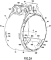
- the seal 20 comprises three regularly distributed spacer tabs, namely two tabs 47 of the type shown in FIG. figure 4B and a tab 47 "of the type shown in figure 4D , as well as four wedging lugs 48.
- the tabs 48 serve as a stop opposing the displacement of the seal towards the rear relative to the belt.
- the seal 20 further comprises in this case a tube position key which, when the clamping device is disposed at the end 1A of the tube 1, determines the angular position of the clamping device relative to the tube.
- this tube position keyer comprises a tube position keyer tab 49 which projects radially outwardly of the seal and which is configured to engage in a slot formed at the end. of the tube.
- the end 1A of the tube has a slot 3 which, in this case, comprises a first slot part 3A forming a notch on the edge 1'A of the tube and a second part 3B forming a shaped window substantially in Y, this window having in this case a closed contour.
- the tube position keying tab 49 engages in the notch 3A and therefore makes it possible to angularly wedge the collar relative to the tube.
- this tube position coding tab 49 is folded backwards from the front edge of the sleeve 40. Its free end 49A is itself folded forward by being clamped on itself.
- the tube position keying tab 49 can also, by its part folded against the sleeve 30, contribute to the wedging of the front edge of the sleeve 30 relative to the sleeve 40. It can also, when its free end 49A is radially straightened , contribute to the bracing to keep the seal away from the belt 12 of the collar.
- the seal 20 also includes an anti-extraction tab 49 '.
- this tab 49 ' is formed by an extension of the rear edge 41B of the sleeve 40 folded forward on the outside towards the front and the free end 49'A of which is slightly straightened.
- this tab 49 ′ projects into a part of the slot 3B of the tube 3.
- the geometries of this slot part and of the tab 49' are such that the tab cooperates with the slot to oppose forward extraction of the seal relative to the tube.
- This tab 49 ′ also performs a function of keying the position of the tube, by angularly wedging the seal relative to the tube 1.
- the end 1A of the tube 1 is provided with the slot 3, so that, when the clamp is tightened, the diameter of the end 1A can be reduced by reducing the width of the slot.
- this slot is bridged on the inside by a solid part of the seal 20.
- Part 3B of the slot 3 forms a window with which the anti-extraction tab 49 'cooperates.
- the spacer tab which has been described (tabs 47, 47 'and 47 ", or even 49) is located on the front edge of the seal, so as not to obstruct the engagement of the end 1A of the tube. 1 between the belt 12 and the seal 20.
- the strip forming the first sleeve 30 is formed from a mica-based material. It is for example a material comprising mica and a silicone-type binder. For example, it may be a material of the type known under the trademark Cogemica Hi-temp® resistant to high temperatures and comprising, by weight, 90% of mica or more and 10% of binder or less.
- the strip forming the second sleeve 40 can be made of metal, in particular stainless steel. We have chosen here to place the metal sleeve inside the other sleeve, because it is the metal sleeve which carries, in one piece with it, the clamping tabs of the other sleeve, these tabs being folded back. outwards.
- the arrangement could be reversed, by placing the metal sleeve on the outside, while achieving suitable retention of the two sleeves with respect to each other.
- the outer sleeve can of course carry the spacer lugs and the seal and / or tube polarizer.
- the figure 6 shows an alternative embodiment which differs only from that which has just been described by the conformation of the slot formed at the end 1A of the tube 1 and, consequently, by the conformation of the lugs which prevent the position of the tube and anti- extraction carried by the seal 20 and, more precisely, by the sleeve 40.
- the slot 3 'formed at the end of the tube 1A comprises two elementary axial slot sections, in particular a front elementary slot section 3'A open on the front edge 1'A of the tube, and a closed elementary slot section 3'B, which forms a window 3'B and which is located at the rear of this slot 3'A and slightly angularly offset with respect to it.
- the sleeve 40 for its part, has a tube position keying tab 149 which is folded back towards the outside of this sleeve 40 and is dimensioned to be able to engage in the open slot portion 3'A of the tube.
- This sleeve 40 also has an anti-extraction tab 149 'folded forward from the rear edge of this sleeve and slightly angularly offset with respect to the tab 149, and whose conformation allows it to engage in the portion of closed slot 3'B to oppose forward extraction of the seal with respect to tube 1.
- the collar 10 is of the open type, which means that the ends of the belt 12 are folded back radially to form tightening tabs 16A and 16B which are able to be displaced with respect to one another. another to tighten the collar.
- these clamping tabs cooperate with a clamping rod 18 formed in this case by the shank of a screw comprising a head 18A which is retained behind the clamping tabs and a nut 18B retained behind the 'Another clamping tab, possibly via spacers 19.
- the rear of a clamping tab is the side of this tab which is opposite to the other clamping tab.
- a slot 15 of the collar is thus formed between the clamping tabs 16A and 16B. The angular positioning of the seal 20 with respect to the collar makes it possible to prevent the ends of the bands in which the sleeves are formed from being located in line with this slot.
- the collar has several series of windows 14 arranged symmetrically with respect to a radial median plane of the collar perpendicular to its axis A. This makes it possible to ensure that the collar can be positioned indifferently in one or the other. direction with respect to this radial median plane (that is to say that its rear edge takes the place of its front edge and vice versa) while allowing correct positioning of the seal in the collar.
Landscapes
- Engineering & Computer Science (AREA)
- General Engineering & Computer Science (AREA)
- Mechanical Engineering (AREA)
- Gasket Seals (AREA)
- Clamps And Clips (AREA)
- Joints That Cut Off Fluids, And Hose Joints (AREA)
Applications Claiming Priority (1)
| Application Number | Priority Date | Filing Date | Title |
|---|---|---|---|
| FR1904668A FR3095683B1 (fr) | 2019-05-03 | 2019-05-03 | Joint d’étanchéité et dispositif et ensemble de serrage comprenant un tel joint d’étanchéité |
Publications (2)
| Publication Number | Publication Date |
|---|---|
| EP3734130A1 true EP3734130A1 (de) | 2020-11-04 |
| EP3734130B1 EP3734130B1 (de) | 2022-12-14 |
Family
ID=67742736
Family Applications (1)
| Application Number | Title | Priority Date | Filing Date |
|---|---|---|---|
| EP20171694.1A Active EP3734130B1 (de) | 2019-05-03 | 2020-04-28 | Klemmvorrichtung mit einer dichtung sowie klemmanordnung mit einer solchen klemmvorrichtung |
Country Status (9)
| Country | Link |
|---|---|
| US (1) | US20200347968A1 (de) |
| EP (1) | EP3734130B1 (de) |
| JP (1) | JP2020183809A (de) |
| KR (1) | KR20200127896A (de) |
| CN (1) | CN111878648A (de) |
| BR (1) | BR102020008387A2 (de) |
| FR (1) | FR3095683B1 (de) |
| MX (1) | MX2020004613A (de) |
| RU (1) | RU2020115105A (de) |
Families Citing this family (2)
| Publication number | Priority date | Publication date | Assignee | Title |
|---|---|---|---|---|
| US11774022B2 (en) | 2020-12-03 | 2023-10-03 | Mueller International, Llc | Pipe fitting with grip ring |
| US12449071B2 (en) * | 2022-05-25 | 2025-10-21 | Mueller International, Llc | Compression fitting |
Citations (7)
| Publication number | Priority date | Publication date | Assignee | Title |
|---|---|---|---|---|
| US4201407A (en) * | 1978-10-23 | 1980-05-06 | Maremont Corporation | Tubular assembly |
| US5588680A (en) * | 1994-12-20 | 1996-12-31 | Bks Company | Pipe lap joint with improved collapsible sealing zone |
| EP1181477A1 (de) | 1999-06-02 | 2002-02-27 | Etablissements CAILLAU | Vorrichtung zum dichten verbinden von zwei glatten rohren |
| US20030205899A1 (en) * | 2002-05-06 | 2003-11-06 | Bishop John P. | Coupling |
| US20060175837A1 (en) * | 2005-02-10 | 2006-08-10 | Breeze-Torca Products, Llc | Pipe clamp with gasketed center rib |
| EP2598785A1 (de) | 2010-07-27 | 2013-06-05 | Etablissements Caillau | Klemmsystem zur verbindung und vormontage eines ersten und zweiten rohrs |
| EP3232107A1 (de) | 2016-04-12 | 2017-10-18 | Etablissements Caillau | Klemmvorrichtung, die eine schlauchklemme und eine manschette umfasst |
Family Cites Families (5)
| Publication number | Priority date | Publication date | Assignee | Title |
|---|---|---|---|---|
| US4473246A (en) * | 1981-11-06 | 1984-09-25 | Michigan Tube Benders | Pipe coupling |
| GB0206804D0 (en) * | 2002-03-22 | 2002-05-01 | Tyco Electronics Raychem Gmbh | Adjustable insert for a duct or bulkhead opening |
| FR2884582B1 (fr) * | 2005-04-13 | 2010-01-08 | Caillau Ets | Dispositif pour l'accouplement etanche de deux tubes lisses |
| CN102472421B (zh) * | 2009-07-24 | 2014-06-18 | 诺玛美国控股有限责任公司 | 用于有槽管搭接头的具有带凸起衬垫的带夹 |
| FR3057047B1 (fr) * | 2016-10-04 | 2019-05-10 | Etablissements Caillau | Systeme de serrage a position angulaire controlee pour le raccordement de deux tubes |
-
2019
- 2019-05-03 FR FR1904668A patent/FR3095683B1/fr active Active
-
2020
- 2020-04-26 CN CN202010336819.0A patent/CN111878648A/zh active Pending
- 2020-04-27 JP JP2020077972A patent/JP2020183809A/ja active Pending
- 2020-04-28 BR BR102020008387-2A patent/BR102020008387A2/pt not_active Application Discontinuation
- 2020-04-28 EP EP20171694.1A patent/EP3734130B1/de active Active
- 2020-04-29 RU RU2020115105A patent/RU2020115105A/ru unknown
- 2020-04-29 US US16/861,313 patent/US20200347968A1/en not_active Abandoned
- 2020-04-29 KR KR1020200052715A patent/KR20200127896A/ko not_active Withdrawn
- 2020-07-13 MX MX2020004613A patent/MX2020004613A/es unknown
Patent Citations (7)
| Publication number | Priority date | Publication date | Assignee | Title |
|---|---|---|---|---|
| US4201407A (en) * | 1978-10-23 | 1980-05-06 | Maremont Corporation | Tubular assembly |
| US5588680A (en) * | 1994-12-20 | 1996-12-31 | Bks Company | Pipe lap joint with improved collapsible sealing zone |
| EP1181477A1 (de) | 1999-06-02 | 2002-02-27 | Etablissements CAILLAU | Vorrichtung zum dichten verbinden von zwei glatten rohren |
| US20030205899A1 (en) * | 2002-05-06 | 2003-11-06 | Bishop John P. | Coupling |
| US20060175837A1 (en) * | 2005-02-10 | 2006-08-10 | Breeze-Torca Products, Llc | Pipe clamp with gasketed center rib |
| EP2598785A1 (de) | 2010-07-27 | 2013-06-05 | Etablissements Caillau | Klemmsystem zur verbindung und vormontage eines ersten und zweiten rohrs |
| EP3232107A1 (de) | 2016-04-12 | 2017-10-18 | Etablissements Caillau | Klemmvorrichtung, die eine schlauchklemme und eine manschette umfasst |
Also Published As
| Publication number | Publication date |
|---|---|
| US20200347968A1 (en) | 2020-11-05 |
| FR3095683A1 (fr) | 2020-11-06 |
| KR20200127896A (ko) | 2020-11-11 |
| RU2020115105A (ru) | 2021-10-29 |
| JP2020183809A (ja) | 2020-11-12 |
| BR102020008387A2 (pt) | 2021-01-12 |
| MX2020004613A (es) | 2020-11-04 |
| EP3734130B1 (de) | 2022-12-14 |
| FR3095683B1 (fr) | 2022-12-09 |
| CN111878648A (zh) | 2020-11-03 |
Similar Documents
| Publication | Publication Date | Title |
|---|---|---|
| EP3217059B1 (de) | Spannanordnung mit einer spannschelle und einzelne vormontageclips | |
| EP2017518B1 (de) | Klemmvorrichtung mit Schlauchklemme und Positionierteil | |
| EP2598785B1 (de) | Klemmsystem zur verbindung und vormontage eines ersten und zweiten rohrs | |
| EP1451498B1 (de) | Spannvorrichtung zur dichten kupplung von zwei rohren mit spannauflagen | |
| EP3189261B1 (de) | Kopplungssystem für zwei rohre | |
| WO2008145919A2 (fr) | Dispositif de serrage | |
| FR2967230A1 (fr) | Collier de serrage articule | |
| EP3734129B1 (de) | Verschlussvorrichtung, die eine schelle und eine dichtungsfuge umfasst | |
| FR3057047A1 (fr) | Systeme de serrage a position angulaire controlee pour le raccordement de deux tubes | |
| EP1319147A1 (de) | Anschlussverbindung zwischen einem rohrförmigen element und einem rohr | |
| EP3150896A1 (de) | Schlauchklemme mit abstandhalter | |
| EP3734130B1 (de) | Klemmvorrichtung mit einer dichtung sowie klemmanordnung mit einer solchen klemmvorrichtung | |
| EP3561360B1 (de) | Spannsystem mit herunterklappbaren spannbacken für den anschluss von rohren | |
| EP0280598B1 (de) | Spannschelle mit Elastizitätsreserve | |
| EP3670988B1 (de) | Spannvorrichtung, die einen riemen und einen dichtungsring umfasst | |
| EP3999766B1 (de) | Kompakte und demontierbare fluidverbindung | |
| EP3795877B1 (de) | Schlauchklemme | |
| FR2884582A1 (fr) | Dispositif pour l'accouplement etanche de deux tubes lisses | |
| EP1456573B1 (de) | Dichte kupplungsvorrichtung fuer zwei starre rohre mit gleichen aussendurchmessern | |
| EP0581678A1 (de) | Radiale Spannvorrichtung zum Verbinden von einem Rohr mit einem Rohrende | |
| EP1131578B1 (de) | Verbindungsklammer und abstandshalter für zwei schellen | |
| EP0807780B1 (de) | Vorrichtung zum dichten Verbinden von zwei glatten Rohren | |
| WO2025181437A1 (fr) | Collier de serrage a oreille de serrage et tige de serrage | |
| EP3213804A1 (de) | Haltevorrichtung für dieselfilter eines kraftfahrzeugs |
Legal Events
| Date | Code | Title | Description |
|---|---|---|---|
| PUAI | Public reference made under article 153(3) epc to a published international application that has entered the european phase |
Free format text: ORIGINAL CODE: 0009012 |
|
| STAA | Information on the status of an ep patent application or granted ep patent |
Free format text: STATUS: THE APPLICATION HAS BEEN PUBLISHED |
|
| AK | Designated contracting states |
Kind code of ref document: A1 Designated state(s): AL AT BE BG CH CY CZ DE DK EE ES FI FR GB GR HR HU IE IS IT LI LT LU LV MC MK MT NL NO PL PT RO RS SE SI SK SM TR |
|
| AX | Request for extension of the european patent |
Extension state: BA ME |
|
| STAA | Information on the status of an ep patent application or granted ep patent |
Free format text: STATUS: REQUEST FOR EXAMINATION WAS MADE |
|
| 17P | Request for examination filed |
Effective date: 20210409 |
|
| RBV | Designated contracting states (corrected) |
Designated state(s): AL AT BE BG CH CY CZ DE DK EE ES FI FR GB GR HR HU IE IS IT LI LT LU LV MC MK MT NL NO PL PT RO RS SE SI SK SM TR |
|
| GRAP | Despatch of communication of intention to grant a patent |
Free format text: ORIGINAL CODE: EPIDOSNIGR1 |
|
| STAA | Information on the status of an ep patent application or granted ep patent |
Free format text: STATUS: GRANT OF PATENT IS INTENDED |
|
| INTG | Intention to grant announced |
Effective date: 20220704 |
|
| GRAS | Grant fee paid |
Free format text: ORIGINAL CODE: EPIDOSNIGR3 |
|
| GRAA | (expected) grant |
Free format text: ORIGINAL CODE: 0009210 |
|
| STAA | Information on the status of an ep patent application or granted ep patent |
Free format text: STATUS: THE PATENT HAS BEEN GRANTED |
|
| AK | Designated contracting states |
Kind code of ref document: B1 Designated state(s): AL AT BE BG CH CY CZ DE DK EE ES FI FR GB GR HR HU IE IS IT LI LT LU LV MC MK MT NL NO PL PT RO RS SE SI SK SM TR |
|
| REG | Reference to a national code |
Ref country code: GB Ref legal event code: FG4D Free format text: NOT ENGLISH |
|
| REG | Reference to a national code |
Ref country code: CH Ref legal event code: EP |
|
| REG | Reference to a national code |
Ref country code: DE Ref legal event code: R096 Ref document number: 602020006862 Country of ref document: DE |
|
| REG | Reference to a national code |
Ref country code: IE Ref legal event code: FG4D Free format text: LANGUAGE OF EP DOCUMENT: FRENCH |
|
| REG | Reference to a national code |
Ref country code: AT Ref legal event code: REF Ref document number: 1537863 Country of ref document: AT Kind code of ref document: T Effective date: 20230115 |
|
| REG | Reference to a national code |
Ref country code: LT Ref legal event code: MG9D |
|
| REG | Reference to a national code |
Ref country code: NL Ref legal event code: MP Effective date: 20221214 |
|
| PG25 | Lapsed in a contracting state [announced via postgrant information from national office to epo] |
Ref country code: SE Free format text: LAPSE BECAUSE OF FAILURE TO SUBMIT A TRANSLATION OF THE DESCRIPTION OR TO PAY THE FEE WITHIN THE PRESCRIBED TIME-LIMIT Effective date: 20221214 Ref country code: NO Free format text: LAPSE BECAUSE OF FAILURE TO SUBMIT A TRANSLATION OF THE DESCRIPTION OR TO PAY THE FEE WITHIN THE PRESCRIBED TIME-LIMIT Effective date: 20230314 Ref country code: LT Free format text: LAPSE BECAUSE OF FAILURE TO SUBMIT A TRANSLATION OF THE DESCRIPTION OR TO PAY THE FEE WITHIN THE PRESCRIBED TIME-LIMIT Effective date: 20221214 Ref country code: FI Free format text: LAPSE BECAUSE OF FAILURE TO SUBMIT A TRANSLATION OF THE DESCRIPTION OR TO PAY THE FEE WITHIN THE PRESCRIBED TIME-LIMIT Effective date: 20221214 |
|
| REG | Reference to a national code |
Ref country code: AT Ref legal event code: MK05 Ref document number: 1537863 Country of ref document: AT Kind code of ref document: T Effective date: 20221214 |
|
| PG25 | Lapsed in a contracting state [announced via postgrant information from national office to epo] |
Ref country code: RS Free format text: LAPSE BECAUSE OF FAILURE TO SUBMIT A TRANSLATION OF THE DESCRIPTION OR TO PAY THE FEE WITHIN THE PRESCRIBED TIME-LIMIT Effective date: 20221214 Ref country code: LV Free format text: LAPSE BECAUSE OF FAILURE TO SUBMIT A TRANSLATION OF THE DESCRIPTION OR TO PAY THE FEE WITHIN THE PRESCRIBED TIME-LIMIT Effective date: 20221214 Ref country code: HR Free format text: LAPSE BECAUSE OF FAILURE TO SUBMIT A TRANSLATION OF THE DESCRIPTION OR TO PAY THE FEE WITHIN THE PRESCRIBED TIME-LIMIT Effective date: 20221214 Ref country code: GR Free format text: LAPSE BECAUSE OF FAILURE TO SUBMIT A TRANSLATION OF THE DESCRIPTION OR TO PAY THE FEE WITHIN THE PRESCRIBED TIME-LIMIT Effective date: 20230315 |
|
| PG25 | Lapsed in a contracting state [announced via postgrant information from national office to epo] |
Ref country code: NL Free format text: LAPSE BECAUSE OF FAILURE TO SUBMIT A TRANSLATION OF THE DESCRIPTION OR TO PAY THE FEE WITHIN THE PRESCRIBED TIME-LIMIT Effective date: 20221214 |
|
| PG25 | Lapsed in a contracting state [announced via postgrant information from national office to epo] |
Ref country code: SM Free format text: LAPSE BECAUSE OF FAILURE TO SUBMIT A TRANSLATION OF THE DESCRIPTION OR TO PAY THE FEE WITHIN THE PRESCRIBED TIME-LIMIT Effective date: 20221214 Ref country code: RO Free format text: LAPSE BECAUSE OF FAILURE TO SUBMIT A TRANSLATION OF THE DESCRIPTION OR TO PAY THE FEE WITHIN THE PRESCRIBED TIME-LIMIT Effective date: 20221214 Ref country code: PT Free format text: LAPSE BECAUSE OF FAILURE TO SUBMIT A TRANSLATION OF THE DESCRIPTION OR TO PAY THE FEE WITHIN THE PRESCRIBED TIME-LIMIT Effective date: 20230414 Ref country code: ES Free format text: LAPSE BECAUSE OF FAILURE TO SUBMIT A TRANSLATION OF THE DESCRIPTION OR TO PAY THE FEE WITHIN THE PRESCRIBED TIME-LIMIT Effective date: 20221214 Ref country code: EE Free format text: LAPSE BECAUSE OF FAILURE TO SUBMIT A TRANSLATION OF THE DESCRIPTION OR TO PAY THE FEE WITHIN THE PRESCRIBED TIME-LIMIT Effective date: 20221214 Ref country code: CZ Free format text: LAPSE BECAUSE OF FAILURE TO SUBMIT A TRANSLATION OF THE DESCRIPTION OR TO PAY THE FEE WITHIN THE PRESCRIBED TIME-LIMIT Effective date: 20221214 Ref country code: AT Free format text: LAPSE BECAUSE OF FAILURE TO SUBMIT A TRANSLATION OF THE DESCRIPTION OR TO PAY THE FEE WITHIN THE PRESCRIBED TIME-LIMIT Effective date: 20221214 |
|
| PG25 | Lapsed in a contracting state [announced via postgrant information from national office to epo] |
Ref country code: SK Free format text: LAPSE BECAUSE OF FAILURE TO SUBMIT A TRANSLATION OF THE DESCRIPTION OR TO PAY THE FEE WITHIN THE PRESCRIBED TIME-LIMIT Effective date: 20221214 Ref country code: PL Free format text: LAPSE BECAUSE OF FAILURE TO SUBMIT A TRANSLATION OF THE DESCRIPTION OR TO PAY THE FEE WITHIN THE PRESCRIBED TIME-LIMIT Effective date: 20221214 Ref country code: IS Free format text: LAPSE BECAUSE OF FAILURE TO SUBMIT A TRANSLATION OF THE DESCRIPTION OR TO PAY THE FEE WITHIN THE PRESCRIBED TIME-LIMIT Effective date: 20230414 Ref country code: AL Free format text: LAPSE BECAUSE OF FAILURE TO SUBMIT A TRANSLATION OF THE DESCRIPTION OR TO PAY THE FEE WITHIN THE PRESCRIBED TIME-LIMIT Effective date: 20221214 |
|
| REG | Reference to a national code |
Ref country code: DE Ref legal event code: R097 Ref document number: 602020006862 Country of ref document: DE |
|
| PLBE | No opposition filed within time limit |
Free format text: ORIGINAL CODE: 0009261 |
|
| STAA | Information on the status of an ep patent application or granted ep patent |
Free format text: STATUS: NO OPPOSITION FILED WITHIN TIME LIMIT |
|
| PG25 | Lapsed in a contracting state [announced via postgrant information from national office to epo] |
Ref country code: DK Free format text: LAPSE BECAUSE OF FAILURE TO SUBMIT A TRANSLATION OF THE DESCRIPTION OR TO PAY THE FEE WITHIN THE PRESCRIBED TIME-LIMIT Effective date: 20221214 |
|
| 26N | No opposition filed |
Effective date: 20230915 |
|
| PG25 | Lapsed in a contracting state [announced via postgrant information from national office to epo] |
Ref country code: SI Free format text: LAPSE BECAUSE OF FAILURE TO SUBMIT A TRANSLATION OF THE DESCRIPTION OR TO PAY THE FEE WITHIN THE PRESCRIBED TIME-LIMIT Effective date: 20221214 |
|
| REG | Reference to a national code |
Ref country code: CH Ref legal event code: PL |
|
| PG25 | Lapsed in a contracting state [announced via postgrant information from national office to epo] |
Ref country code: LU Free format text: LAPSE BECAUSE OF NON-PAYMENT OF DUE FEES Effective date: 20230428 |
|
| REG | Reference to a national code |
Ref country code: BE Ref legal event code: MM Effective date: 20230430 |
|
| PG25 | Lapsed in a contracting state [announced via postgrant information from national office to epo] |
Ref country code: MC Free format text: LAPSE BECAUSE OF FAILURE TO SUBMIT A TRANSLATION OF THE DESCRIPTION OR TO PAY THE FEE WITHIN THE PRESCRIBED TIME-LIMIT Effective date: 20221214 |
|
| PG25 | Lapsed in a contracting state [announced via postgrant information from national office to epo] |
Ref country code: MC Free format text: LAPSE BECAUSE OF FAILURE TO SUBMIT A TRANSLATION OF THE DESCRIPTION OR TO PAY THE FEE WITHIN THE PRESCRIBED TIME-LIMIT Effective date: 20221214 Ref country code: LI Free format text: LAPSE BECAUSE OF NON-PAYMENT OF DUE FEES Effective date: 20230430 Ref country code: CH Free format text: LAPSE BECAUSE OF NON-PAYMENT OF DUE FEES Effective date: 20230430 |
|
| REG | Reference to a national code |
Ref country code: IE Ref legal event code: MM4A |
|
| PG25 | Lapsed in a contracting state [announced via postgrant information from national office to epo] |
Ref country code: BE Free format text: LAPSE BECAUSE OF NON-PAYMENT OF DUE FEES Effective date: 20230430 |
|
| PG25 | Lapsed in a contracting state [announced via postgrant information from national office to epo] |
Ref country code: IE Free format text: LAPSE BECAUSE OF NON-PAYMENT OF DUE FEES Effective date: 20230428 |
|
| PG25 | Lapsed in a contracting state [announced via postgrant information from national office to epo] |
Ref country code: IE Free format text: LAPSE BECAUSE OF NON-PAYMENT OF DUE FEES Effective date: 20230428 |
|
| PG25 | Lapsed in a contracting state [announced via postgrant information from national office to epo] |
Ref country code: BG Free format text: LAPSE BECAUSE OF FAILURE TO SUBMIT A TRANSLATION OF THE DESCRIPTION OR TO PAY THE FEE WITHIN THE PRESCRIBED TIME-LIMIT Effective date: 20221214 |
|
| PG25 | Lapsed in a contracting state [announced via postgrant information from national office to epo] |
Ref country code: BG Free format text: LAPSE BECAUSE OF FAILURE TO SUBMIT A TRANSLATION OF THE DESCRIPTION OR TO PAY THE FEE WITHIN THE PRESCRIBED TIME-LIMIT Effective date: 20221214 |
|
| PGFP | Annual fee paid to national office [announced via postgrant information from national office to epo] |
Ref country code: DE Payment date: 20250411 Year of fee payment: 6 |
|
| PGFP | Annual fee paid to national office [announced via postgrant information from national office to epo] |
Ref country code: GB Payment date: 20250417 Year of fee payment: 6 |
|
| PGFP | Annual fee paid to national office [announced via postgrant information from national office to epo] |
Ref country code: IT Payment date: 20250409 Year of fee payment: 6 |
|
| PGFP | Annual fee paid to national office [announced via postgrant information from national office to epo] |
Ref country code: FR Payment date: 20250422 Year of fee payment: 6 |
|
| PG25 | Lapsed in a contracting state [announced via postgrant information from national office to epo] |
Ref country code: CY Free format text: LAPSE BECAUSE OF FAILURE TO SUBMIT A TRANSLATION OF THE DESCRIPTION OR TO PAY THE FEE WITHIN THE PRESCRIBED TIME-LIMIT; INVALID AB INITIO Effective date: 20200428 |
|
| PG25 | Lapsed in a contracting state [announced via postgrant information from national office to epo] |
Ref country code: HU Free format text: LAPSE BECAUSE OF FAILURE TO SUBMIT A TRANSLATION OF THE DESCRIPTION OR TO PAY THE FEE WITHIN THE PRESCRIBED TIME-LIMIT; INVALID AB INITIO Effective date: 20200428 |
|
| PG25 | Lapsed in a contracting state [announced via postgrant information from national office to epo] |
Ref country code: TR Free format text: LAPSE BECAUSE OF FAILURE TO SUBMIT A TRANSLATION OF THE DESCRIPTION OR TO PAY THE FEE WITHIN THE PRESCRIBED TIME-LIMIT Effective date: 20221214 |