EP3734261A1 - Dispositif d'inspection à rayons x - Google Patents
Dispositif d'inspection à rayons x Download PDFInfo
- Publication number
- EP3734261A1 EP3734261A1 EP18893911.0A EP18893911A EP3734261A1 EP 3734261 A1 EP3734261 A1 EP 3734261A1 EP 18893911 A EP18893911 A EP 18893911A EP 3734261 A1 EP3734261 A1 EP 3734261A1
- Authority
- EP
- European Patent Office
- Prior art keywords
- sample
- placement unit
- rays
- rotation mechanism
- ray
- Prior art date
- Legal status (The legal status is an assumption and is not a legal conclusion. Google has not performed a legal analysis and makes no representation as to the accuracy of the status listed.)
- Granted
Links
Images






Classifications
-
- G—PHYSICS
- G01—MEASURING; TESTING
- G01N—INVESTIGATING OR ANALYSING MATERIALS BY DETERMINING THEIR CHEMICAL OR PHYSICAL PROPERTIES
- G01N23/00—Investigating or analysing materials by the use of wave or particle radiation, e.g. X-rays or neutrons, not covered by groups G01N3/00 – G01N17/00, G01N21/00 or G01N22/00
- G01N23/20—Investigating or analysing materials by the use of wave or particle radiation, e.g. X-rays or neutrons, not covered by groups G01N3/00 – G01N17/00, G01N21/00 or G01N22/00 by using diffraction of the radiation by the materials, e.g. for investigating crystal structure; by using scattering of the radiation by the materials, e.g. for investigating non-crystalline materials; by using reflection of the radiation by the materials
- G01N23/20008—Constructional details of analysers, e.g. characterised by X-ray source, detector or optical system; Accessories therefor; Preparing specimens therefor
- G01N23/20016—Goniometers
-
- G—PHYSICS
- G01—MEASURING; TESTING
- G01N—INVESTIGATING OR ANALYSING MATERIALS BY DETERMINING THEIR CHEMICAL OR PHYSICAL PROPERTIES
- G01N23/00—Investigating or analysing materials by the use of wave or particle radiation, e.g. X-rays or neutrons, not covered by groups G01N3/00 – G01N17/00, G01N21/00 or G01N22/00
- G01N23/20—Investigating or analysing materials by the use of wave or particle radiation, e.g. X-rays or neutrons, not covered by groups G01N3/00 – G01N17/00, G01N21/00 or G01N22/00 by using diffraction of the radiation by the materials, e.g. for investigating crystal structure; by using scattering of the radiation by the materials, e.g. for investigating non-crystalline materials; by using reflection of the radiation by the materials
- G01N23/207—Diffractometry using detectors, e.g. using a probe in a central position and one or more displaceable detectors in circumferential positions
-
- G—PHYSICS
- G01—MEASURING; TESTING
- G01N—INVESTIGATING OR ANALYSING MATERIALS BY DETERMINING THEIR CHEMICAL OR PHYSICAL PROPERTIES
- G01N2223/00—Investigating materials by wave or particle radiation
- G01N2223/05—Investigating materials by wave or particle radiation by diffraction, scatter or reflection
- G01N2223/056—Investigating materials by wave or particle radiation by diffraction, scatter or reflection diffraction
-
- G—PHYSICS
- G01—MEASURING; TESTING
- G01N—INVESTIGATING OR ANALYSING MATERIALS BY DETERMINING THEIR CHEMICAL OR PHYSICAL PROPERTIES
- G01N2223/00—Investigating materials by wave or particle radiation
- G01N2223/30—Accessories, mechanical or electrical features
- G01N2223/33—Accessories, mechanical or electrical features scanning, i.e. relative motion for measurement of successive object-parts
- G01N2223/3306—Accessories, mechanical or electrical features scanning, i.e. relative motion for measurement of successive object-parts object rotates
-
- G—PHYSICS
- G01—MEASURING; TESTING
- G01N—INVESTIGATING OR ANALYSING MATERIALS BY DETERMINING THEIR CHEMICAL OR PHYSICAL PROPERTIES
- G01N2223/00—Investigating materials by wave or particle radiation
- G01N2223/30—Accessories, mechanical or electrical features
- G01N2223/33—Accessories, mechanical or electrical features scanning, i.e. relative motion for measurement of successive object-parts
- G01N2223/3308—Accessories, mechanical or electrical features scanning, i.e. relative motion for measurement of successive object-parts object translates
-
- G—PHYSICS
- G01—MEASURING; TESTING
- G01N—INVESTIGATING OR ANALYSING MATERIALS BY DETERMINING THEIR CHEMICAL OR PHYSICAL PROPERTIES
- G01N2223/00—Investigating materials by wave or particle radiation
- G01N2223/30—Accessories, mechanical or electrical features
- G01N2223/331—Accessories, mechanical or electrical features rocking curve analysis
-
- G—PHYSICS
- G01—MEASURING; TESTING
- G01N—INVESTIGATING OR ANALYSING MATERIALS BY DETERMINING THEIR CHEMICAL OR PHYSICAL PROPERTIES
- G01N2223/00—Investigating materials by wave or particle radiation
- G01N2223/50—Detectors
-
- G—PHYSICS
- G01—MEASURING; TESTING
- G01N—INVESTIGATING OR ANALYSING MATERIALS BY DETERMINING THEIR CHEMICAL OR PHYSICAL PROPERTIES
- G01N2223/00—Investigating materials by wave or particle radiation
- G01N2223/60—Specific applications or type of materials
- G01N2223/611—Specific applications or type of materials patterned objects; electronic devices
- G01N2223/6116—Specific applications or type of materials patterned objects; electronic devices semiconductor wafer
-
- G—PHYSICS
- G01—MEASURING; TESTING
- G01N—INVESTIGATING OR ANALYSING MATERIALS BY DETERMINING THEIR CHEMICAL OR PHYSICAL PROPERTIES
- G01N2223/00—Investigating materials by wave or particle radiation
- G01N2223/60—Specific applications or type of materials
- G01N2223/645—Specific applications or type of materials quality control
Definitions
- the present invention relates to an X-ray inspection device suitable for use in a semiconductor manufacturing field, etc., such as a technical field for manufacturing an element having a multilayer structure in which multiple thin films are laminated on a substrate.
- a semiconductor, etc. such as an element having a multilayer structure in which multiple thin films are laminated on a substrate vary according to the state of a thin film to be formed, such as the film thickness, density, crystallinity, etc. of the thin film. Microfabrication and integration of these elements have recently progressed, and this tendency has become remarkable. Therefore, a thin film inspection device capable of accurately measuring the states of formed films has been required.
- TEM cross-sectional transmission electron microscope
- film thickness inspection device using optical interference or ellipsometry are suitable for the in-line process, but have insufficient precision for measurements of thin films of several nm.
- Wafers for inspection which are discarded after used have imposed a large burden in cost on semiconductor device makers. Particularly, the diameter of semiconductor wafers has recently increased, so that the cost of one blanket wafer has also increased.
- An X-ray inspection device comprising:
- the goniometer includes:
- sample placement unit positioning mechanism includes:
- the X-ray irradiation unit is configured to focus X-rays in a lateral direction that intersects perpendicularly to an optical axis of the X-rays and is parallel to the ⁇ s-axis, and also focus X-rays in a longitudinal direction that intersects perpendicularly to an optical axis of the X-rays and intersects perpendicularly to the ⁇ s-axis.
- the ⁇ rotation mechanism is driven to irradiate the surface of the sample with focused X-rays from the X-ray irradiation unit in a state where the surface of the sample placed in the sample placement unit is vertically oriented, and the incident angle of the X-rays to the sample is changed by the ⁇ s rotation mechanism, whereby the rocking curve measurement of in-plane diffraction can be performed.
- the surface of the sample is irradiated with the X-rays which are focused in the form of a minute spot by the X-ray irradiation unit, high-resolution and high-precision measurement can be performed by detecting the diffracted X-rays appearing from the minute spot.
- the X-ray irradiation unit is preferably configured to focus X-rays within 100 ⁇ m or less, to full width at half maximum of the peak, in each of the lateral direction and the longitudinal direction at the measurement point.
- the Y movement mechanism is preferably configured so that a direction (Y direction) in which the sample placement unit is moved in a state where the sample placement unit is horizontally arranged by the ⁇ rotation mechanism is parallel to the ⁇ s-axis and the ⁇ d-axis.
- a direction (Y direction) in which the sample placement unit is moved in a state where the sample placement unit is horizontally arranged by the ⁇ rotation mechanism is parallel to the ⁇ s-axis and the ⁇ d-axis.
- the Y movement mechanism it is also possible for the Y movement mechanism to have a function as a sample exchange mechanism for arranging the sample placement unit at a preset sample exchange position by moving (horizontally moving) the sample placement unit in the Y direction.
- the Y movement mechanism is configured so that the direction in which the sample placement unit is moved by the Y movement mechanism (that is, Y direction) is parallel to the ⁇ s-axis that is a rotation center of the first rotation member and the ⁇ d-axis that is a rotation center of the second rotation member, so that the sample placement unit can be horizontally moved to the sample exchange position without interfering with a rotation path of the X-ray irradiation unit installed on the first rotation member and a rotation path of the two-dimensional X-ray detector installed on the second rotation member. Therefore, it is possible to perform a so-called in-line X-ray inspection which is incorporated in a manufacturing process for a film-formed product and inspects a thin film as an inspection target in real time.
- the ⁇ rotation mechanism is installed on the Y movement mechanism to reduce a torque required to drive the ⁇ rotation mechanism. As a result, it is possible to reduce the size of the ⁇ rotation mechanism and realize smooth driving with a small amount of electric power.
- the X-ray inspection device of the present invention may be configured to include a controller having a control function of controlling the sample placement unit positioning mechanism, the goniometer including the first and second rotation members, and the X-ray irradiation unit to perform a rocking curve measurement of in-plane diffraction.
- the controller is configured to have a control function of:
- controller may be configured as follows. In other words, the controller may be configured to have a control function of:
- controller may be configured as follows.
- controller may be configured to have a control function of:
- the X-ray inspection device of the present invention may be configured to include a controller having a control function of controlling the sample placement unit positioning mechanism, the goniometer including the first and second rotation members, and the X-ray irradiation unit to perform an in-plane diffraction measurement.
- the controller is configured to have a control function of:
- the X-ray inspection device of the present invention may be configured to include a controller having a control function of controlling the sample placement unit positioning mechanism, the goniometer including the first and second rotation members, and the X-ray irradiation unit to perform a pole measurement.
- the controller is configured to have a control function of driving the ⁇ rotation mechanism to rotate the surface of the sample placed in the sample placement unit about the ⁇ -axis, thereby setting a tilt angle ⁇ for the pole measurement within a range of 0° to 90°, and driving the ⁇ rotation mechanism to rotate the surface of the sample placed in the sample placement unit about the ⁇ -axis, thereby setting an in-plane rotation angle ⁇ for the pole measurement, whereby the pole measurement is performed.
- Figs. 1A and 1B are diagrams showing an overall structure of an X-ray inspection device according to an embodiment of the present invention.
- Figs. 2A and 2B are diagrams schematically showing a main structure of the device.
- the X-ray inspection device includes a sample stage 10, a goniometer 20, a sample placement unit positioning mechanism (which may be simply referred to as “positioning mechanism” below) 30, an X-ray irradiation unit 40, and an X-ray detector 50.
- a sample placement unit 11 is formed on an upper surface of the sample stage 10.
- a semiconductor wafer (sample S) as an inspection target is placed in the sample placement unit 11.
- the sample stage 10 is driven by the positioning mechanism 30.
- a measurement point P is set in advance in the X-ray inspection device. By driving the sample stage 10 with the positioning mechanism 30, a measurement target site of the sample S placed in the sample placement unit 11 is positioned at the measurement point P.
- a mechanism (not shown) for fixing the sample S is installed in the sample placement unit 11. This sample fixing mechanism prevents the sample S from falling off the sample placement unit 11 even when the surface of the sample placement unit 11 (the upper surface of the sample stage 10) is vertically oriented as described later.
- the fixing mechanism for the sample S may be adopted, for example, a configuration in which a plurality of suction nozzles are opened on the surface of the sample placement unit 11, and hollow portions of the suction nozzles are vacuum-sucked by a suction device such as a vacuum pump, whereby the sample S is adsorbed on the sample placement unit 11.
- a suction device such as a vacuum pump
- a publicly known sample fixing mechanism other than the above mechanism may be adopted.
- the goniometer 20 includes a 8s rotation mechanism and a ⁇ d rotation mechanism incorporated in the goniometer main body 21.
- the ⁇ s rotation mechanism rotates a first rotation arm (rotation member) 22 in a direction of an arrow 8s in Fig. 2A about a ⁇ s-axis that passes through a preset measurement point P and extends in a horizontal direction.
- the X-ray irradiation unit 40 is installed on the first rotation arm 22. An incident angle of X-rays from the X-ray irradiation unit 40 to the sample S is set by the movement of the first rotation arm 22.
- the ⁇ d rotation mechanism rotates a second rotation arm (rotation member) 23 in a direction of an arrow ⁇ d in Fig. 2A about a ⁇ d-axis that passes through the preset measurement point P and extends in the horizontal direction.
- the X-ray detector 50 is installed on the second rotation arm 23.
- a scanning angle of the X-ray detector 50 is set by the movement of the first rotation arm 22.
- the movement of the first rotation arm 22 causes the X-ray detector 50 to be arranged at a position where diffracted X-rays appearing from the surface of the sample S according to the Bragg's law are detected.
- ⁇ s-axis and ⁇ d-axis are rotation center axes on the same axis.
- the positioning mechanism 30 includes a ⁇ rotation mechanism 31, an X movement mechanism 32, a Y movement mechanism 33, a Z movement mechanism 34, a ⁇ rotation mechanism 35, and a ⁇ rotation mechanism 36 for moving the sample placement unit 11 in respective directions.
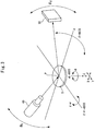
- Fig. 3 is a diagram schematically showing the moving directions of the sample placement unit 11 by the positioning mechanism 30.
- the positioning mechanism 30 will be described with reference to Fig. 3 and Figs. 2A and 2B .
- the ⁇ rotation mechanism 31 rotates the sample placement unit 11 in a direction of an arrow ⁇ in the figure about a ⁇ -axis orthogonal to the surface of the sample S placed in the sample placement unit 11.
- the X movement mechanism 32 linearly moves the sample placement unit 11 and the ⁇ -axis in an X direction intersecting perpendicularly to the ⁇ s-axis and the ⁇ d-axis.
- the Y movement mechanism 33 linearly moves the sample placement unit 11 and the ⁇ -axis in a Y direction intersecting perpendicularly to the X direction.
- the Z movement mechanism 34 moves the sample placement unit 11 in a Z direction orthogonal to the surface of the sample S placed in the sample placement unit 11.
- the ⁇ rotation mechanism 35 rotates the sample placement unit 11 and the ⁇ -axis in a direction of an arrow ⁇ in the figure around a ⁇ -axis that is orthogonal to the ⁇ s-axis and the ⁇ d-axis at the measurement point P and extends horizontally.
- the ⁇ rotation mechanism 36 rotates the sample placement unit 11 and the ⁇ -axis in a direction of an arrow ⁇ in the figure around a ⁇ -axis that is orthogonal to the ⁇ -axis at the measurement point P and extends in parallel to the surface of the sample placed in the sample placement unit 11. Further, the ⁇ rotation mechanism 36 is rotated in a direction of an arrow ⁇ in the figure around the ⁇ -axis by the ⁇ rotation mechanism 35.
- a sample exchange position (not shown) is preset in the X-ray inspection device.
- the sample placement unit 11 formed on the upper surface of the sample stage 10 is transported to this sample exchange position.
- a sample exchange device such as a robot arm takes out an inspected sample S from the sample placement unit 11 and places a new sample S as an inspection target in the sample placement unit 11.
- the Y movement mechanism 33 is configured to function as a sample exchange mechanism for moving the sample placement unit 11 to the sample exchange position.
- a direction in which the sample placement unit 11 is moved while the sample placement unit 11 is horizontally arranged by the ⁇ rotation mechanism 35 (Y direction) is set to be in parallel to the ⁇ s-axis and the ⁇ d-axis.
- the sample exchange position is set on a movement path on which the sample placement unit 11 is moved in the direction.
- the ⁇ rotation mechanism 31 is installed on the Y movement mechanism 33 to reduce the torque required to drive the ⁇ rotation mechanism 31. As a result, the ⁇ rotation mechanism 31 can be decreased in size and smoothly driven with a small amount of electric power.
- the X-ray inspection device of the present embodiment is configured so that the ⁇ rotation mechanism 36, the X movement mechanism 32, the Y movement mechanism 33, the Z movement mechanism 34, the ⁇ rotation mechanism 31 and the sample stage 10 are installed on the ⁇ rotation mechanism 35 as shown in Figs. 1A to 2B .
- the X-ray inspection device is configured so that the ⁇ rotation mechanism 36 is rotated around the ⁇ -axis by the ⁇ rotation mechanism 35.
- the X movement mechanism 32 and the Y movement mechanism 33 are installed on the ⁇ rotation mechanism 36.
- the Z movement mechanism 34 is installed on the Y movement mechanism 33.
- the ⁇ rotation mechanism 31 is installed on the Z movement mechanism 34.
- the sample stage 10 is installed on the ⁇ rotation mechanism 31.
- the X-ray irradiation unit 40 has a function of monochromatizing X-rays generated from an X-ray tube into characteristic X-rays having a specific wavelength and also focusing the X-rays on one place.
- An X-ray irradiation path of the X-ray irradiation unit 40 is adjusted so that focusing X-rays are irradiated onto a preset measurement point P. As described above, a measurement target site of the sample S placed in the sample placement unit 11 is positioned at the measurement point P.
- a two-dimensional X-ray detector is adopted as the X-ray detector 50.
- the two-dimensional X-ray detector has a two-dimensionally configured planar X-ray detector, and can collectively record diffracted X-rays appearing from the surface of the sample S in this planar X-ray detector. Therefore, the two-dimensional X-ray detector has a feature that the time required for measurement can be shortened as compared with a one-dimensional X-ray detector such as a proportional counter (PC) or a scintillation counter (SC).
- PC proportional counter
- SC scintillation counter
- the X-ray irradiation unit 40 shown in Figs. 4A to 7B includes an X-ray tube 41, a first X-ray optical element 42, a second X-ray optical element 43, and a focusing slit 44 (slit member) as constituent elements. These constituent elements are incorporated in a unit main body (not shown).
- the unit main body is configured to be small in dimension and shape so that it is installable in the first rotation arm 22.
- the focusing slit 44 is shown only in Fig. 7A , and omitted in Figs. 4A, 4B and 5 .
- a micro focus X-ray tube having an electron beam focus size of about ⁇ 100 ⁇ m on a target may be used as the X-ray tube 41.
- Copper (Cu), molybdenum (Mo), iron (Fe), cobalt (Co), tungsten (W), chromium (Cr), silver (Ag), gold (Au) or the like may be used as a target material as required.
- the first and second X-ray optical elements 42 and 43 have a function of receiving X-rays a1 radiated from the X-ray tube 41, extracting only characteristic X-rays having a specific wavelength and focusing the extracted characteristic X-ray a2 on the surface of a sample placed on the sample stage 10.
- the first X-ray optical element 42 and the second X-ray optical element 43 are arranged so that surfaces 42a and 43a thereof which receive X-rays and reflect characteristic X-rays (hereinafter merely referred to as "surfaces") are orthogonal to each other.
- the first X-ray optical element 42 and the second X-ray optical element 43 focus the characteristic X-rays a2 having the specific wavelength so that the characteristic X-rays a2 form a square minute spot on the surface of the sample placed on the sample stage 10.
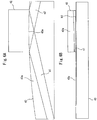
- Fig. 7B is an enlarged plan view schematically showing a position at which the characteristic X-rays a2 are focused on the surface of the sample (semiconductor wafer).
- the first X-ray optical element 42 and the second X-ray optical element 43 are arranged in a side-by-side manner in which one sides thereof are in contact with each other.
- the present invention is not limited to this arrangement, and they may be arranged in an in-series manner called as Kirkpatrick-Baez (KB).
- a position at which the characteristic X-rays reflected and extracted by the first and second X-ray optical elements 42 and 43 are focused on the surface of the sample placed on the sample stage 10 is a measurement point P.
- the respective surfaces 42a and 43a of the X-ray optical elements 42 and 43 are formed to be concavely curved.
- the first X-ray optical element 42 focuses X-rays in a longitudinal direction that is orthogonal to the optical axis of the X-rays and orthogonal to the ⁇ s-axis.
- the second X-ray optical element 43 focuses the X-rays in a lateral direction that is orthogonal to the optical axis of the X-rays and parallel to the ⁇ s-axis.
- the first X-ray optical element 42 is constituted by a crystal material having high crystallinity.
- the first X-ray optical element 42 is constituted by a crystal material having an extremely small inherent rocking curve width (that is, angular range in which a parallel beam can be reflected). Crystal materials corresponding to perfect crystals having extremely little lattice defect and impurities correspond to the crystal material having the extremely small inherent rocking curve width as described above.
- the first X-ray optical element 42 is constituted by a crystal material having an inherent rocking curve width of 0.06° or less.
- the characteristic X-rays a2 extracted from the crystal material described above high angular resolution of 0.06° or less can be obtained in X-ray thin film measurements.
- Ge (111) or Si (111) may be used as the crystal material.
- Ge (1 1 1) is used, a rocking curve width of 0.06° or less is obtained.
- Si (1 1 1) is used, a rocking curve width of 0.02° or less is obtained.
- X-rays can be focused within 100 ⁇ m or less, to full width at half maximum of the peak, in the longitudinal direction at the measurement point P.
- the first X-ray optical element 42 has a function of extracting only characteristic X-rays having a specific wavelength and monochromatizing the extracted characteristic X-rays.
- the second X-ray optical element 43 is constituted by a multilayer mirror.
- the second X-ray optical element 43 has a function of extracting only characteristic X-rays having a specific wavelength and monochromatizing the extracted characteristic X-rays.
- the second X-ray optical element 43 is adjusted so as to extract the characteristic X-rays having the same wavelength as the characteristic X-rays extracted by the first X-ray optical element 42.
- X-rays can be focused within 100 ⁇ m or less, to full width at half maximum of the peak, in the lateral direction at the measurement point P.
- X-rays b1 which are emitted from the X-ray tube 41 and incident to the surface 43a of the second X-ray optical element 43 are monochromatized and reflected by the X-ray optical element 43, travel so as to be focused in the lateral direction, and then are incident to the surface 42a of the first X-ray optical element 42. Then, X-rays b2 incident to the surface 42a of the first X-ray optical element 42 are monochromatized and reflected by the X-ray optical element 42, travel so as to be focused in the longitudinal direction, and are irradiated to the measurement point P shown in Figs. 4A and 4B .
- X-rays c1 which are emitted from the X-ray tube 41 and incident to the surface 42a of the first X-ray optical element 42 are monochromatized and reflected by the X-ray optical element 42, travel so as to be focused in the longitudinal direction, then are incident to the surface 43a of the second X-ray optical element 43. Then, X-rays c2 incident to the surface 43a of the second X-ray optical element 43 travel so as to be focused in the lateral direction, and then are irradiated to the measurement point P shown in Figs. 4A and 4B .
- X-rays a1 emitted from the X-ray tube 41 are reflected once by each of the surface 42a of the first X-ray optical element 42 and the surface 43a of the second X-ray optical element 43, and during this process, only characteristic X-rays a2 having a specific wavelength are extracted, and the characteristic X-rays a2 are focused on the measurement point P.
- Patent Document 2 and Patent Document 3 disclose an X-ray beam adjustment system configured by combining a perfect crystal and multilayer optical components.
- these documents do not disclose a configuration which is optimized for an X-ray inspection device using a semiconductor wafer as an inspection target sample.
- the focusing slit 44 is arranged so as to partially shield the characteristic X-rays a2 reflected by the first and second X-ray optical elements 42 and 43 from both sides in the longitudinal direction described above.
- the focusing slit 44 has a function of restricting the focusing in the longitudinal direction of the focusing X-rays a2 reflected by the first and second X-ray optical elements 42 and 43.
- X-rays can be focused on a minute area by the first X-ray optical element 42, the second X-ray optical element 43 and the focusing slit 44. Accordingly, it is possible to perform a thin film measurement by irradiating X-rays to an extremely minute inspection area on the surface of a semiconductor wafer.
- the first X-ray optical element 42 is constituted by a crystal material having an extremely small inherent rocking curve width, extremely high angular resolution can be obtained in the X-ray thin film measurement by using characteristic X-rays a2 extracted with the crystal material as described above.
- Fig. 8 is a block diagram showing a control system (controller) of the X-ray inspection device.
- the control of the X-ray irradiation unit 40 is performed by an XG (X-ray Generator) controller 101.
- XG X-ray Generator
- a positioning controller 102 drives and controls the positioning mechanism 30.
- the goniometer 20 is driven and controlled by a goniometer controller 103.
- Each of respective components of the XG controller 101, the positioning controller 102, and the goniometer controller 103 operates based on setting information sent from a central processing unit (CPU) 100.
- the setting information is stored as a recipe in a storage unit 110 in advance, and it is read out by the central processing unit (CPU) 100 and output to each of the above-mentioned components.
- the X-ray detector 50 is controlled by a counting control circuit 104.
- Each of these components and the central processing unit 100 is configured by a computer and installed in the storage unit 110 in advance, and executes each control operation according to a control program.
- the X-ray inspection device is equipped with an operation unit 201 including a keyboard, a mouse and the like for allowing an operator to input various settings necessary for the operation of the device. Further, the X-ray inspection device is equipped with a display unit 202 including a liquid crystal display or the like, and a communication unit 203 that executes data communication via a network.
- the in-plane X-ray diffraction measurement is a method of causing X-rays a to be barely incident to the surface of a thin film sample S and measuring diffracted X-rays b diffracted at crystal lattice planes orthogonal to the surface of the thin film sample S according to the Bragg's law as shown in Fig. 9 .
- This in-plane X-ray diffraction measurement makes it possible to obtain information regarding the size and orientation of a crystal in a direction orthogonal to the surface of the thin film sample S.
- the control system (controller) shown in Fig. 8 includes a control function of controlling the positioning mechanism 30, the goniometer 20, and the X-ray irradiation unit 40 to perform the in-plane diffraction measurement.
- the in-plane diffraction measurement can be performed in a state where the surface of the sample S placed in the sample placement unit 11 is oriented vertically.
- the positioning controller 102 drives and controls the ⁇ rotation mechanism 35 constituting the positioning mechanism 30 to vertically orient the surface of the sample S placed in the sample placement unit 11.
- the positioning controller 102 drives and controls the Z movement mechanism 34 to align the inspection target site of the sample S placed in the sample placement unit 11 with the height of the measurement point P. Further, the positioning controller 102 drives and controls the ⁇ rotation mechanism 31, the X movement mechanism 32, and the Y movement mechanism 33 to position the inspection target site of the sample S at the measurement point P under a preset orientation.
- the positioning controller 102 drives and controls the ⁇ rotation mechanism 36 so that the incident X-rays a from the X-ray irradiation unit 40 is adjusted to be incident to the surface of the sample S at a grazing angle ( ⁇ ).
- ⁇ grazing angle
- the goniometer controller 103 drives and controls the ⁇ s rotation mechanism of the goniometer 20 to set the incident angle of the X-rays a from the X-ray irradiation unit 40 to the sample S.
- the XG controller 101 controls the X-ray irradiation unit 40 to irradiate the sample S with the X-rays a. Inside the sample S, X-rays are diffracted according to the Bragg's law at crystal lattice planes orthogonal to the sample surface. Then, the diffracted X-rays b appear from the surface of the sample S.
- the X-ray irradiation unit 40 can irradiate the sample S with the X-rays a that are focused on a minute area with high resolution. Therefore, X-ray diffraction measurement can be performed by irradiating the sample S with a bundle of X-rays a within the focusing angle range thereof in a lump. Further, by adopting a two-dimensional X-ray detector as the X-ray detector 50, a bundle of diffracted X-rays b which have been diffracted in a certain angle range in connection with the bundle of X-rays a in the focusing angle range can be detected in a lump, and the measurement time can be shortened.
- the in-plane diffraction is a diffraction phenomenon which occurs at the crystal lattice planes orthogonal to the surface of the thin film sample S according to the Bragg's law as shown in Fig. 9 when X-rays are caused to be incident to the crystal lattice planes.
- the in-plane orientation of the sample S can be evaluated by performing the rocking curve measurement with focusing on such in-plane diffraction.
- the rocking curve measurement with focusing on such in-plane diffraction.
- the X-ray detector 50 is fixed in a direction in which the X-rays are diffracted from the lattice planes according to the Bragg's law (an angle direction of 2 ⁇ with respect to the optical axis of the incident X-rays).
- the sample S is minutely rotated in the in-plane direction ( ⁇ direction), and the rocking curve measurement is performed.
- the control system (controller) shown in Fig. 8 has a control function of controlling the positioning mechanism 30, the goniometer 20, and the X-ray irradiation unit 40 to perform rocking curve measurement of in-plane diffraction.
- control program for performing the rocking curve measurement of in-plane diffraction is installed in advance in the storage unit 110 of the control system (controller) shown in Fig. 8 , and the setting information necessary for the measurement described above is stored as a recipe in advance.
- the central processing unit (CPU) 100 reads out necessary setting information according to the control program and outputs it to each component of the control system.
- the rocking curve measurement of in-plane diffraction can be performed while the surface of the sample placed in the sample placement unit 11 is oriented vertically.
- the positioning controller 102 drives and controls the ⁇ rotation mechanism 35 constituting the positioning mechanism 30 to vertically orient the surface of the sample placed in the sample placement unit 11.
- the positioning controller 102 drives and controls the Z movement mechanism 34 to align the inspection target site of the sample S placed in the sample placement unit 11 with the height of the measurement point P. Further, the positioning controller 102 drives and controls the ⁇ rotation mechanism 31, the X movement mechanism 32, and the Y movement mechanism 33 to position the inspection target site of the sample S at the measurement point P under a preset orientation.
- the positioning controller 102 drives and controls the ⁇ rotation mechanism 36 so that the incident X-rays from the X-ray irradiation unit 40 are adjusted to be incident to the surface of the sample S at a grazing angle ( ⁇ ).
- the goniometer controller 103 drives and controls the ⁇ s rotation mechanism of the goniometer 20 to set the incident angle of the X-rays a from the X-ray irradiation unit 40 to the sample S.
- the goniometer controller 103 drives and controls the ⁇ d rotation mechanism of the goniometer 20 to place the X-ray detector 50 at a position where diffracted X-rays appearing from the sample S according to the Bragg's law are detected.
- the XG controller 101 controls the X-ray irradiation unit 40 to irradiate the sample S with X-rays a. Then, the counting control circuit 104 controls the X-ray detector 50 to detect diffracted X-rays b appearing from the surface of the sample S by the X-ray detector 50.
- the goniometer controller 103 drives and controls the ⁇ s rotation mechanism of the goniometer 20 to change the incident angle of the X-rays to the sample S.
- This operation of changing the incident angle corresponds to the operation of minutely rotating the sample S in the in-plane direction ( ⁇ direction) in Fig. 12 . With this operation, the rocking curve measurement of in-plane diffraction is performed.
- the operation of minutely rotating the sample S in the in-plane direction ( ⁇ direction) may also be performed by driving and controlling the ⁇ rotation mechanism 31 shown in Figs. 10A, 10B and 11 by the positioning controller 102 and also controlling the X movement mechanism 32 and the Y movement mechanism 33 so that the X movement mechanism 32 and the Y movement mechanism 33 interlock with the driving of the ⁇ rotation mechanism 31.
- the ⁇ rotation mechanism 31 since the ⁇ rotation mechanism 31 is installed just below the sample stage 10 (see Figs. 2A and 2B ), when the X movement mechanism 32 and the Y movement mechanism 33 are driven and controlled to position the measurement target site of the sample S at the measurement point P, the ⁇ rotation mechanism 31 may be moved in the XY direction together with the sample S, so that the ⁇ -axis may be deviated from the measurement point P. Therefore, a rotation angle at the measurement point P during minute rotation around the ⁇ -axis deviated from the measurement point P is necessary to be corrected to a rotation angle in a state where no deviation occurs.
- the X movement mechanism 32 and the Y movement mechanism 33 are driven and controlled interlockingly together with the ⁇ rotation mechanism 31, thereby correcting the rotation operation in the ⁇ direction.
- the X-ray irradiation unit 40 can irradiate the sample S with the X-rays a that are focused on a minute area with high resolution, so that the X-ray diffraction measurement can be performed by irradiating the sample S with a bundle of X-rays a within the focusing angle range thereof in a lump.
- a bundle of diffracted X-rays b which have been diffracted in a certain angle range in connection with the bundle of X-rays a in the focusing angle range can be detected in a lump. Therefore, as shown in Fig. 12 , it is also possible to perform the rocking curve measuring method of in-plane diffraction in a short time without minutely rotating the sample S in the in-plane direction ( ⁇ direction) .
- the incident angle ⁇ of X-rays to the sample surface is changed within a range of 2° or more. Therefore, with respect to X-rays to be irradiated from the X-ray irradiation unit 40 to the sample surface, it is preferable that the focusing angle thereof is set to 2° or more by the focusing slit 44 to irradiate the surface of the sample with X-rays in the angle range of 2° or more.
- a slit or the like may be provided to narrow down the X-rays to be irradiated to the sample S.
- the X-ray inspection device can perform the rocking curve measurement using in-plane diffraction, for example, on a SiGe (silicon germanium) epitaxial thin film or the like formed on a substrate.
- SiGe silicon germanium
- the following rocking curve measurement of in-plane diffraction can be performed on a SiGe thin film (SGOI: SiGe on Insulator) on a SiO 2 thin film formed on a silicon substrate as a measurement target.
- SiGe thin film SiGe on Insulator
- a SiGe thin film is crystal-grown on a silicon substrate in which an Si (100) plane is parallel to a substrate surface, irradiated with oxygen ions, and then subjected to a high temperature treatment under an appropriate condition to form a SiO 2 film between the silicon substrate and the SiGe film, thereby manufacturing SGOI.
- the lattice constant in the lateral direction is relaxed more than Si due to the presence of the SiO 2 film.
- the condition for forming the SiO 2 film is not appropriate, there is a risk that dislocation occurs.
- the SiGe thin film has a very small thickness of about several tens nm, X-rays having a high incident angle are transmitted through the SiGe thin film, and thus sufficient diffraction lines cannot be obtained.
- the rocking curve measurement on SiGe (400) may be performed according to the following procedure.
- sample S A substrate on which SGOI is formed (sample S) is placed and fixed on the sample stage 10, and the ⁇ rotation mechanism 35 is driven to position the substrate approximately perpendicular to the horizontal plane.
- the ⁇ rotation mechanism 35 or ⁇ rotation mechanism 36 is driven and adjusted to place the substrate so that X-rays can be barely incident to the substrate.
- the ⁇ rotation mechanism 31 or the goniometer 20 is driven and adjusted, and the substrate and the X-ray irradiation unit 40 are set at an angle at which X-rays are subjected to Bragg reflection at the Si crystal lattice planes (400).
- This setting makes it possible to detect peak intensities of diffracted X-rays reflected from the (400) planes of the Si substrate crystal and diffracted X-rays reflected from the SiGe (400) planes in a direction which is slightly deviated from that of the former diffracted X-rays.
- the X-ray detector 50 is arranged so that the diffracted X-rays from the Si substrate crystal and the diffracted X-rays from SiGe can be detected in a lump.
- the X-ray irradiation unit 40 can irradiate the surface with monochromatic X-rays to be focused on a minute area with high resolution, it is possible to irradiate the substrate with a bundle of X-rays in the focusing angle range in a lump. Therefore, the rocking curve measurement can be performed in an extremely short time without scanning the X-ray irradiation unit 40, the X-ray detector 50, the substrate, and the like.
- the two-dimensional detector is used as the X-ray detector 50 in the X-ray inspection device according to the present embodiment, it is not essential to scan the X-ray detector 50 in accordance with the X-ray source.
- the rocking curve measurement can also be performed by scanning the ⁇ rotation mechanism 31, the X movement mechanism 32, and the Y movement mechanism 33 around the measurement point of the sample as a rotation center while driving and adjusting them.
- the rocking curve measurement based on in-plane diffraction can be performed on the SiGe epitaxial thin film and the like with high accuracy and at high speed, and it is possible to play a very important role for analysis and management of the crystal quality of the thin film.
- the control system (controller) shown in Fig. 8 includes a control function of controlling the positioning mechanism 30, the goniometer 20, and the X-ray irradiation unit 40 to perform the pole measurement.
- a control program for performing the pole measurement is installed in advance in the storage unit 110 of the control system (controller) shown in Fig. 8 . Furthermore, setting information required for the pole measurement is stored as a recipe in advance in the storage unit 110.
- the central processing unit (CPU) 100 reads out necessary setting information according to the control program and outputs it to each component of the control system.
- the positioning controller 102 drives and controls the ⁇ rotation mechanism 35 constituting the positioning mechanism 30 to rotate the surface of the sample S placed in the sample placement unit 11 about the ⁇ - axis, whereby the tilt angle ⁇ of the pole measurement is changed within a range of 0° to 90°.
- the positioning controller 102 drives and controls the ⁇ rotation mechanism 31 constituting the positioning mechanism 30 to rotate the surface of the sample S placed in the sample placement unit 11 about the ⁇ -axis, whereby the in-plane rotation angle ⁇ of the pole measurement is changed.
- the XG controller 101 controls the X-ray irradiation unit 40 fixed at a certain position to irradiate the sample S with X-rays a. Then, the counting control circuit 104 controls the X-ray detector 50 so that the X-ray detector 50 detects diffracted X-rays diffracted from the sample at a certain position.
- the X-ray inspection device targets a semiconductor wafer flowing through a semiconductor manufacturing line for inspection.
- the present invention is not limited to this mode, and is also applicable to, for example, X-ray inspection in which a minute site of a semiconductor element is set as a measurement target site in a post-processing of the semiconductor manufacturing line.
- the functions of the in-plane X-ray diffraction measurement, the rocking curve measurement of in-plane diffraction, and the pole measurement have been described.
- the X-ray inspection device of the present invention is not limited to these measurements, and can be applied to normal X-ray diffraction measurement, rocking curve measurement, X-ray reflectivity measurement, reciprocal lattice map measurement, etc.
- the X-ray inspection device shown in Figs. 2A and 2B is configured so that the X movement mechanism 32 is provided between the Y movement mechanism 33 and the ⁇ rotation mechanism 36, but it may be configured so that as shown in Figs. 14A and 14B , the X movement mechanism 32 is provided below the ⁇ rotation mechanism 35, and not only the sample stage 10, the ⁇ rotation mechanism 31, the Z movement mechanism 34 and the Y movement mechanism 33, but also the ⁇ rotation mechanism 36 and the ⁇ rotation mechanism 35 are also moved linearly in the X direction.
Landscapes
- Chemical & Material Sciences (AREA)
- Crystallography & Structural Chemistry (AREA)
- Physics & Mathematics (AREA)
- Health & Medical Sciences (AREA)
- Life Sciences & Earth Sciences (AREA)
- Analytical Chemistry (AREA)
- Biochemistry (AREA)
- General Health & Medical Sciences (AREA)
- General Physics & Mathematics (AREA)
- Immunology (AREA)
- Pathology (AREA)
- Analysing Materials By The Use Of Radiation (AREA)
Applications Claiming Priority (2)
| Application Number | Priority Date | Filing Date | Title |
|---|---|---|---|
| JP2017253019 | 2017-12-28 | ||
| PCT/JP2018/032810 WO2019130663A1 (fr) | 2017-12-28 | 2018-09-05 | Dispositif d'inspection à rayons x |
Publications (3)
| Publication Number | Publication Date |
|---|---|
| EP3734261A1 true EP3734261A1 (fr) | 2020-11-04 |
| EP3734261A4 EP3734261A4 (fr) | 2021-09-08 |
| EP3734261B1 EP3734261B1 (fr) | 2025-08-13 |
Family
ID=67063355
Family Applications (1)
| Application Number | Title | Priority Date | Filing Date |
|---|---|---|---|
| EP18893911.0A Active EP3734261B1 (fr) | 2017-12-28 | 2018-09-05 | Dispositif d'inspection à rayons x |
Country Status (8)
| Country | Link |
|---|---|
| US (1) | US11079345B2 (fr) |
| EP (1) | EP3734261B1 (fr) |
| JP (1) | JP6938054B2 (fr) |
| KR (1) | KR102409643B1 (fr) |
| CN (1) | CN111527400A (fr) |
| SG (1) | SG11202006227TA (fr) |
| TW (1) | TWI739034B (fr) |
| WO (1) | WO2019130663A1 (fr) |
Families Citing this family (9)
| Publication number | Priority date | Publication date | Assignee | Title |
|---|---|---|---|---|
| KR102621750B1 (ko) * | 2019-06-24 | 2024-01-05 | 에스엠에스 그룹 게엠베하 | 다결정 제품의 소재 특성 측정 장치 및 방법 |
| JP7300718B2 (ja) * | 2019-12-13 | 2023-06-30 | 株式会社リガク | 制御装置、システム、方法およびプログラム |
| EP4100721B1 (fr) * | 2020-02-05 | 2024-01-10 | Carl Zeiss SMT GmbH | Réflectomètre extrème-uv |
| KR20230090144A (ko) * | 2021-12-14 | 2023-06-21 | 주식회사 엘지에너지솔루션 | 전극조립체의 외경측정장치와 외경측정방법 |
| CN114113175B (zh) * | 2021-12-28 | 2025-01-07 | 苏州锂影科技有限公司 | 一种x射线衍射仪用两轴薄膜样品台 |
| US20250180495A1 (en) * | 2022-03-07 | 2025-06-05 | Rigaku Corporation | X-ray diffraction data processing device and x-ray analysis device |
| JP7793430B2 (ja) * | 2022-03-10 | 2026-01-05 | キオクシア株式会社 | 評価装置 |
| WO2025111538A1 (fr) * | 2023-11-22 | 2025-05-30 | Hauptman-Woodward Medical Research Institute | Goniomètre ayant un support de positionnement et procédé d'utilisation |
| WO2025249016A1 (fr) * | 2024-05-29 | 2025-12-04 | 株式会社リガク | Dispositif d'inspection par rayons x |
Family Cites Families (21)
| Publication number | Priority date | Publication date | Assignee | Title |
|---|---|---|---|---|
| JPH0786484B2 (ja) * | 1989-05-17 | 1995-09-20 | 株式会社フジクラ | ゴニオメータヘッド |
| GB9216461D0 (en) * | 1992-08-03 | 1992-09-16 | Smith James A | Eucentric goniometer or motion system |
| JP2630249B2 (ja) * | 1994-02-16 | 1997-07-16 | 日本電気株式会社 | 全反射蛍光x線分析装置 |
| JPH1144662A (ja) * | 1997-07-29 | 1999-02-16 | Rigaku Corp | 微小部x線分析装置 |
| JP2000258366A (ja) * | 1999-03-05 | 2000-09-22 | Rigaku Corp | 微小部x線回折装置 |
| US6937694B2 (en) * | 1999-06-10 | 2005-08-30 | Rigaku Corporation | Pole measuring method |
| US6301330B1 (en) * | 1999-07-30 | 2001-10-09 | Hypernex, Inc. | Apparatus and method for texture analysis on semiconductor wafers |
| JP2003294657A (ja) * | 2002-03-29 | 2003-10-15 | Asahi Kasei Corp | 結晶歪み度合いの分析方法 |
| JP3697246B2 (ja) * | 2003-03-26 | 2005-09-21 | 株式会社リガク | X線回折装置 |
| WO2004114325A2 (fr) | 2003-06-13 | 2004-12-29 | Osmic, Inc. | Systeme de conditionnement de faisceau |
| JP3912606B2 (ja) * | 2004-10-26 | 2007-05-09 | 株式会社リガク | X線薄膜検査装置と、プロダクトウエーハの薄膜検査装置およびその方法 |
| JP4784984B2 (ja) * | 2006-04-10 | 2011-10-05 | 株式会社リガク | X線回折装置とその制御方法 |
| JP5963453B2 (ja) * | 2011-03-15 | 2016-08-03 | 株式会社荏原製作所 | 検査装置 |
| JP5346057B2 (ja) * | 2011-04-26 | 2013-11-20 | 株式会社リガク | X線分析装置の試料冷却装置及びx線分析装置 |
| JP2013231700A (ja) * | 2012-05-01 | 2013-11-14 | Tokyo Electron Ltd | X線検査方法及びx線検査装置 |
| JP5998666B2 (ja) | 2012-06-14 | 2016-09-28 | 富士通株式会社 | X線分析装置及びx線分析方法 |
| US9417196B2 (en) * | 2013-10-10 | 2016-08-16 | Bruker Axs Inc. | X-ray diffraction based crystal centering method using an active pixel array sensor in rolling shutter mode |
| JP2015184092A (ja) * | 2014-03-24 | 2015-10-22 | 桑原 章二 | X線分析装置 |
| WO2016059672A1 (fr) * | 2014-10-14 | 2016-04-21 | 株式会社リガク | Dispositif de contrôle par rayons x de film mince |
| JP6656519B2 (ja) | 2016-06-15 | 2020-03-04 | 株式会社リガク | X線回折装置 |
| KR102348995B1 (ko) * | 2016-07-15 | 2022-01-10 | 가부시키가이샤 리가쿠 | X선 검사 장치, x선 박막 검사 방법 및 로킹 커브 측정 방법 |
-
2018
- 2018-09-05 EP EP18893911.0A patent/EP3734261B1/fr active Active
- 2018-09-05 JP JP2019562739A patent/JP6938054B2/ja active Active
- 2018-09-05 SG SG11202006227TA patent/SG11202006227TA/en unknown
- 2018-09-05 WO PCT/JP2018/032810 patent/WO2019130663A1/fr not_active Ceased
- 2018-09-05 CN CN201880084358.3A patent/CN111527400A/zh active Pending
- 2018-09-05 KR KR1020207021564A patent/KR102409643B1/ko active Active
- 2018-09-05 US US16/958,556 patent/US11079345B2/en active Active
- 2018-09-17 TW TW107132650A patent/TWI739034B/zh active
Also Published As
| Publication number | Publication date |
|---|---|
| EP3734261B1 (fr) | 2025-08-13 |
| US11079345B2 (en) | 2021-08-03 |
| JPWO2019130663A1 (ja) | 2020-12-17 |
| KR102409643B1 (ko) | 2022-06-16 |
| SG11202006227TA (en) | 2020-07-29 |
| TW201930865A (zh) | 2019-08-01 |
| WO2019130663A1 (fr) | 2019-07-04 |
| EP3734261A4 (fr) | 2021-09-08 |
| US20210063326A1 (en) | 2021-03-04 |
| TWI739034B (zh) | 2021-09-11 |
| KR20200099597A (ko) | 2020-08-24 |
| JP6938054B2 (ja) | 2021-09-22 |
| CN111527400A (zh) | 2020-08-11 |
Similar Documents
| Publication | Publication Date | Title |
|---|---|---|
| EP3734261B1 (fr) | Dispositif d'inspection à rayons x | |
| US10876978B2 (en) | X-ray inspecting device, X-ray thin film inspecting method, and method for measuring rocking curve | |
| JP7308233B2 (ja) | 小角x線散乱計測計 | |
| TWI803621B (zh) | X射線設備及用於樣本對準之方法 | |
| KR102144281B1 (ko) | X선 박막 검사 장치 | |
| KR102144273B1 (ko) | X선 박막 검사 장치 | |
| US11703464B2 (en) | Small-angle x-ray scatterometry | |
| TW202613538A (zh) | X射線檢查裝置 | |
| TW202613539A (zh) | X射線檢查裝置 | |
| WO2025249016A1 (fr) | Dispositif d'inspection par rayons x | |
| TW202613540A (zh) | X射線檢查裝置 | |
| JP2025179983A (ja) | X線検査装置 | |
| JP2025179981A (ja) | X線検査装置 | |
| JP2025179982A (ja) | X線検査装置 |
Legal Events
| Date | Code | Title | Description |
|---|---|---|---|
| STAA | Information on the status of an ep patent application or granted ep patent |
Free format text: STATUS: THE INTERNATIONAL PUBLICATION HAS BEEN MADE |
|
| PUAI | Public reference made under article 153(3) epc to a published international application that has entered the european phase |
Free format text: ORIGINAL CODE: 0009012 |
|
| STAA | Information on the status of an ep patent application or granted ep patent |
Free format text: STATUS: REQUEST FOR EXAMINATION WAS MADE |
|
| 17P | Request for examination filed |
Effective date: 20200625 |
|
| AK | Designated contracting states |
Kind code of ref document: A1 Designated state(s): AL AT BE BG CH CY CZ DE DK EE ES FI FR GB GR HR HU IE IS IT LI LT LU LV MC MK MT NL NO PL PT RO RS SE SI SK SM TR |
|
| AX | Request for extension of the european patent |
Extension state: BA ME |
|
| DAV | Request for validation of the european patent (deleted) | ||
| DAX | Request for extension of the european patent (deleted) | ||
| A4 | Supplementary search report drawn up and despatched |
Effective date: 20210811 |
|
| RIC1 | Information provided on ipc code assigned before grant |
Ipc: G01N 23/207 20180101ALI20210805BHEP Ipc: G01N 23/20016 20180101AFI20210805BHEP |
|
| STAA | Information on the status of an ep patent application or granted ep patent |
Free format text: STATUS: EXAMINATION IS IN PROGRESS |
|
| 17Q | First examination report despatched |
Effective date: 20230615 |
|
| GRAP | Despatch of communication of intention to grant a patent |
Free format text: ORIGINAL CODE: EPIDOSNIGR1 |
|
| STAA | Information on the status of an ep patent application or granted ep patent |
Free format text: STATUS: GRANT OF PATENT IS INTENDED |
|
| INTG | Intention to grant announced |
Effective date: 20250410 |
|
| GRAJ | Information related to disapproval of communication of intention to grant by the applicant or resumption of examination proceedings by the epo deleted |
Free format text: ORIGINAL CODE: EPIDOSDIGR1 |
|
| STAA | Information on the status of an ep patent application or granted ep patent |
Free format text: STATUS: EXAMINATION IS IN PROGRESS |
|
| GRAS | Grant fee paid |
Free format text: ORIGINAL CODE: EPIDOSNIGR3 |
|
| STAA | Information on the status of an ep patent application or granted ep patent |
Free format text: STATUS: GRANT OF PATENT IS INTENDED |
|
| GRAP | Despatch of communication of intention to grant a patent |
Free format text: ORIGINAL CODE: EPIDOSNIGR1 |
|
| GRAA | (expected) grant |
Free format text: ORIGINAL CODE: 0009210 |
|
| STAA | Information on the status of an ep patent application or granted ep patent |
Free format text: STATUS: THE PATENT HAS BEEN GRANTED |
|
| INTC | Intention to grant announced (deleted) | ||
| INTG | Intention to grant announced |
Effective date: 20250708 |
|
| AK | Designated contracting states |
Kind code of ref document: B1 Designated state(s): AL AT BE BG CH CY CZ DE DK EE ES FI FR GB GR HR HU IE IS IT LI LT LU LV MC MK MT NL NO PL PT RO RS SE SI SK SM TR |
|
| REG | Reference to a national code |
Ref country code: GB Ref legal event code: FG4D |
|
| REG | Reference to a national code |
Ref country code: CH Ref legal event code: EP |
|
| P01 | Opt-out of the competence of the unified patent court (upc) registered |
Free format text: CASE NUMBER: UPC_APP_0591_3734261/2025 Effective date: 20250718 |
|
| REG | Reference to a national code |
Ref country code: DE Ref legal event code: R096 Ref document number: 602018084646 Country of ref document: DE |
|
| REG | Reference to a national code |
Ref country code: IE Ref legal event code: FG4D |
|
| PGFP | Annual fee paid to national office [announced via postgrant information from national office to epo] |
Ref country code: DE Payment date: 20250919 Year of fee payment: 8 |
|
| REG | Reference to a national code |
Ref country code: NL Ref legal event code: MP Effective date: 20250813 |
|
| PG25 | Lapsed in a contracting state [announced via postgrant information from national office to epo] |
Ref country code: IS Free format text: LAPSE BECAUSE OF FAILURE TO SUBMIT A TRANSLATION OF THE DESCRIPTION OR TO PAY THE FEE WITHIN THE PRESCRIBED TIME-LIMIT Effective date: 20251213 |
|
| PG25 | Lapsed in a contracting state [announced via postgrant information from national office to epo] |
Ref country code: NO Free format text: LAPSE BECAUSE OF FAILURE TO SUBMIT A TRANSLATION OF THE DESCRIPTION OR TO PAY THE FEE WITHIN THE PRESCRIBED TIME-LIMIT Effective date: 20251113 |
|
| REG | Reference to a national code |
Ref country code: LT Ref legal event code: MG9D |
|
| PG25 | Lapsed in a contracting state [announced via postgrant information from national office to epo] |
Ref country code: PT Free format text: LAPSE BECAUSE OF FAILURE TO SUBMIT A TRANSLATION OF THE DESCRIPTION OR TO PAY THE FEE WITHIN THE PRESCRIBED TIME-LIMIT Effective date: 20251215 |
|
| PG25 | Lapsed in a contracting state [announced via postgrant information from national office to epo] |
Ref country code: FI Free format text: LAPSE BECAUSE OF FAILURE TO SUBMIT A TRANSLATION OF THE DESCRIPTION OR TO PAY THE FEE WITHIN THE PRESCRIBED TIME-LIMIT Effective date: 20250813 |
|
| PG25 | Lapsed in a contracting state [announced via postgrant information from national office to epo] |
Ref country code: NL Free format text: LAPSE BECAUSE OF FAILURE TO SUBMIT A TRANSLATION OF THE DESCRIPTION OR TO PAY THE FEE WITHIN THE PRESCRIBED TIME-LIMIT Effective date: 20250813 Ref country code: HR Free format text: LAPSE BECAUSE OF FAILURE TO SUBMIT A TRANSLATION OF THE DESCRIPTION OR TO PAY THE FEE WITHIN THE PRESCRIBED TIME-LIMIT Effective date: 20250813 |
|
| PG25 | Lapsed in a contracting state [announced via postgrant information from national office to epo] |
Ref country code: GR Free format text: LAPSE BECAUSE OF FAILURE TO SUBMIT A TRANSLATION OF THE DESCRIPTION OR TO PAY THE FEE WITHIN THE PRESCRIBED TIME-LIMIT Effective date: 20251114 |
|
| PG25 | Lapsed in a contracting state [announced via postgrant information from national office to epo] |
Ref country code: SE Free format text: LAPSE BECAUSE OF FAILURE TO SUBMIT A TRANSLATION OF THE DESCRIPTION OR TO PAY THE FEE WITHIN THE PRESCRIBED TIME-LIMIT Effective date: 20250813 |
|
| PG25 | Lapsed in a contracting state [announced via postgrant information from national office to epo] |
Ref country code: LV Free format text: LAPSE BECAUSE OF FAILURE TO SUBMIT A TRANSLATION OF THE DESCRIPTION OR TO PAY THE FEE WITHIN THE PRESCRIBED TIME-LIMIT Effective date: 20250813 |
|
| PG25 | Lapsed in a contracting state [announced via postgrant information from national office to epo] |
Ref country code: PL Free format text: LAPSE BECAUSE OF FAILURE TO SUBMIT A TRANSLATION OF THE DESCRIPTION OR TO PAY THE FEE WITHIN THE PRESCRIBED TIME-LIMIT Effective date: 20250813 Ref country code: BG Free format text: LAPSE BECAUSE OF FAILURE TO SUBMIT A TRANSLATION OF THE DESCRIPTION OR TO PAY THE FEE WITHIN THE PRESCRIBED TIME-LIMIT Effective date: 20250813 |
|
| PG25 | Lapsed in a contracting state [announced via postgrant information from national office to epo] |
Ref country code: RS Free format text: LAPSE BECAUSE OF FAILURE TO SUBMIT A TRANSLATION OF THE DESCRIPTION OR TO PAY THE FEE WITHIN THE PRESCRIBED TIME-LIMIT Effective date: 20251113 |
|
| PG25 | Lapsed in a contracting state [announced via postgrant information from national office to epo] |
Ref country code: ES Free format text: LAPSE BECAUSE OF FAILURE TO SUBMIT A TRANSLATION OF THE DESCRIPTION OR TO PAY THE FEE WITHIN THE PRESCRIBED TIME-LIMIT Effective date: 20250813 |
|
| REG | Reference to a national code |
Ref country code: AT Ref legal event code: MK05 Ref document number: 1825153 Country of ref document: AT Kind code of ref document: T Effective date: 20250813 |
|
| PG25 | Lapsed in a contracting state [announced via postgrant information from national office to epo] |
Ref country code: RO Free format text: LAPSE BECAUSE OF FAILURE TO SUBMIT A TRANSLATION OF THE DESCRIPTION OR TO PAY THE FEE WITHIN THE PRESCRIBED TIME-LIMIT Effective date: 20250813 |
|
| PG25 | Lapsed in a contracting state [announced via postgrant information from national office to epo] |
Ref country code: SM Free format text: LAPSE BECAUSE OF FAILURE TO SUBMIT A TRANSLATION OF THE DESCRIPTION OR TO PAY THE FEE WITHIN THE PRESCRIBED TIME-LIMIT Effective date: 20250813 |
|
| PG25 | Lapsed in a contracting state [announced via postgrant information from national office to epo] |
Ref country code: DK Free format text: LAPSE BECAUSE OF FAILURE TO SUBMIT A TRANSLATION OF THE DESCRIPTION OR TO PAY THE FEE WITHIN THE PRESCRIBED TIME-LIMIT Effective date: 20250813 |
|
| PG25 | Lapsed in a contracting state [announced via postgrant information from national office to epo] |
Ref country code: AT Free format text: LAPSE BECAUSE OF FAILURE TO SUBMIT A TRANSLATION OF THE DESCRIPTION OR TO PAY THE FEE WITHIN THE PRESCRIBED TIME-LIMIT Effective date: 20250813 |
|
| PG25 | Lapsed in a contracting state [announced via postgrant information from national office to epo] |
Ref country code: IT Free format text: LAPSE BECAUSE OF FAILURE TO SUBMIT A TRANSLATION OF THE DESCRIPTION OR TO PAY THE FEE WITHIN THE PRESCRIBED TIME-LIMIT Effective date: 20250813 |
|
| PG25 | Lapsed in a contracting state [announced via postgrant information from national office to epo] |
Ref country code: CZ Free format text: LAPSE BECAUSE OF FAILURE TO SUBMIT A TRANSLATION OF THE DESCRIPTION OR TO PAY THE FEE WITHIN THE PRESCRIBED TIME-LIMIT Effective date: 20250813 |
|
| REG | Reference to a national code |
Ref country code: CH Ref legal event code: H13 Free format text: ST27 STATUS EVENT CODE: U-0-0-H10-H13 (AS PROVIDED BY THE NATIONAL OFFICE) Effective date: 20260425 |
|
| PG25 | Lapsed in a contracting state [announced via postgrant information from national office to epo] |
Ref country code: EE Free format text: LAPSE BECAUSE OF FAILURE TO SUBMIT A TRANSLATION OF THE DESCRIPTION OR TO PAY THE FEE WITHIN THE PRESCRIBED TIME-LIMIT Effective date: 20250813 Ref country code: SK Free format text: LAPSE BECAUSE OF FAILURE TO SUBMIT A TRANSLATION OF THE DESCRIPTION OR TO PAY THE FEE WITHIN THE PRESCRIBED TIME-LIMIT Effective date: 20250813 |