EP3734344A1 - Système de lentille et dispositif d'imagerie - Google Patents
Système de lentille et dispositif d'imagerie Download PDFInfo
- Publication number
- EP3734344A1 EP3734344A1 EP18897714.4A EP18897714A EP3734344A1 EP 3734344 A1 EP3734344 A1 EP 3734344A1 EP 18897714 A EP18897714 A EP 18897714A EP 3734344 A1 EP3734344 A1 EP 3734344A1
- Authority
- EP
- European Patent Office
- Prior art keywords
- lens
- refractive power
- object side
- lens group
- negative
- Prior art date
- Legal status (The legal status is an assumption and is not a legal conclusion. Google has not performed a legal analysis and makes no representation as to the accuracy of the status listed.)
- Withdrawn
Links
- 238000003384 imaging method Methods 0.000 title description 5
- 230000005499 meniscus Effects 0.000 claims description 56
- 230000003287 optical effect Effects 0.000 claims description 17
- 230000004075 alteration Effects 0.000 description 58
- 230000004907 flux Effects 0.000 description 10
- 206010010071 Coma Diseases 0.000 description 6
- 201000009310 astigmatism Diseases 0.000 description 5
- 230000002093 peripheral effect Effects 0.000 description 4
- 239000006185 dispersion Substances 0.000 description 3
- 230000002349 favourable effect Effects 0.000 description 3
- 230000002547 anomalous effect Effects 0.000 description 2
- 230000000694 effects Effects 0.000 description 2
- 238000005452 bending Methods 0.000 description 1
- 230000007423 decrease Effects 0.000 description 1
- 238000010586 diagram Methods 0.000 description 1
- 239000011521 glass Substances 0.000 description 1
Images






Classifications
-
- G—PHYSICS
- G02—OPTICS
- G02B—OPTICAL ELEMENTS, SYSTEMS OR APPARATUS
- G02B13/00—Optical objectives specially designed for the purposes specified below
- G02B13/04—Reversed telephoto objectives
-
- G—PHYSICS
- G02—OPTICS
- G02B—OPTICAL ELEMENTS, SYSTEMS OR APPARATUS
- G02B13/00—Optical objectives specially designed for the purposes specified below
- G02B13/24—Optical objectives specially designed for the purposes specified below for reproducing or copying at short object distances
-
- G—PHYSICS
- G02—OPTICS
- G02B—OPTICAL ELEMENTS, SYSTEMS OR APPARATUS
- G02B13/00—Optical objectives specially designed for the purposes specified below
- G02B13/06—Panoramic objectives; So-called "sky lenses" including panoramic objectives having reflecting surfaces
-
- G—PHYSICS
- G02—OPTICS
- G02B—OPTICAL ELEMENTS, SYSTEMS OR APPARATUS
- G02B13/00—Optical objectives specially designed for the purposes specified below
- G02B13/18—Optical objectives specially designed for the purposes specified below with lenses having one or more non-spherical faces, e.g. for reducing geometrical aberration
-
- G—PHYSICS
- G02—OPTICS
- G02B—OPTICAL ELEMENTS, SYSTEMS OR APPARATUS
- G02B15/00—Optical objectives with means for varying the magnification
- G02B15/14—Optical objectives with means for varying the magnification by axial movement of one or more lenses or groups of lenses relative to the image plane for continuously varying the equivalent focal length of the objective
- G02B15/16—Optical objectives with means for varying the magnification by axial movement of one or more lenses or groups of lenses relative to the image plane for continuously varying the equivalent focal length of the objective with interdependent non-linearly related movements between one lens or lens group, and another lens or lens group
- G02B15/177—Optical objectives with means for varying the magnification by axial movement of one or more lenses or groups of lenses relative to the image plane for continuously varying the equivalent focal length of the objective with interdependent non-linearly related movements between one lens or lens group, and another lens or lens group having a negative front lens or group of lenses
-
- G—PHYSICS
- G02—OPTICS
- G02B—OPTICAL ELEMENTS, SYSTEMS OR APPARATUS
- G02B27/00—Optical systems or apparatus not provided for by any of the groups G02B1/00 - G02B26/00, G02B30/00
- G02B27/0025—Optical systems or apparatus not provided for by any of the groups G02B1/00 - G02B26/00, G02B30/00 for optical correction, e.g. distorsion, aberration
-
- G—PHYSICS
- G02—OPTICS
- G02B—OPTICAL ELEMENTS, SYSTEMS OR APPARATUS
- G02B7/00—Mountings, adjusting means, or light-tight connections, for optical elements
- G02B7/02—Mountings, adjusting means, or light-tight connections, for optical elements for lenses
- G02B7/04—Mountings, adjusting means, or light-tight connections, for optical elements for lenses with mechanism for focusing or varying magnification
-
- G—PHYSICS
- G02—OPTICS
- G02B—OPTICAL ELEMENTS, SYSTEMS OR APPARATUS
- G02B9/00—Optical objectives characterised both by the number of the components and their arrangements according to their sign, i.e. + or -
- G02B9/64—Optical objectives characterised both by the number of the components and their arrangements according to their sign, i.e. + or - having more than six components
-
- G—PHYSICS
- G02—OPTICS
- G02B—OPTICAL ELEMENTS, SYSTEMS OR APPARATUS
- G02B15/00—Optical objectives with means for varying the magnification
- G02B15/14—Optical objectives with means for varying the magnification by axial movement of one or more lenses or groups of lenses relative to the image plane for continuously varying the equivalent focal length of the objective
- G02B15/22—Optical objectives with means for varying the magnification by axial movement of one or more lenses or groups of lenses relative to the image plane for continuously varying the equivalent focal length of the objective with movable lens means specially adapted for focusing at close distances
Definitions
- the present invention relates to a lens system and an image pickup apparatus.
- Japanese Laid-open Patent Publication No. 2001-228391 discloses a retrofocus-type, inner-focus, wide-angle lens system that has a three-group configuration, a half angle of view of around 44°, and an F number of around 3.5.
- This wide-angle lens system is composed, in order from the object side, of a negative first lens group, a positive second lens group, and a positive third lens group that includes a stop. During focusing, the second lens group moves in the direction of the optical axis.
- One aspect of the present invention is a lens system for image pickup including, in order from an object side: a first lens group that has negative refractive power and is fixed during focusing; a second lens group that has positive refractive power and moves during focusing; a third lens group that has positive refractive power and is fixed during focusing; and a fourth lens group that has a stop disposed on the object side, is fixed during focusing, has positive refractive power, and is disposed closest to an image plane side.
- This lens system is a retrofocus type with a negative-positive-positive-positive four-group configuration, and is an inner-focus system where only the second lens group moves along the optical axis during focusing.
- the lens system has a stop disposed between the third lens group and the fourth lens group that are fixed.
- a retrofocus-type system where the lens group closest to the object side has negative refractive power is suitable for a wide-angle lens, but since the positive refractive power is strong, for an inner-focus system, there is a tendency for the magnification to change when lenses with positive refractive power move during focusing.
- this lens system uses a configuration where the rear group that has positive refractive power is divided into three groups to disperse the refractive power, thereby suppressing the power of the second lens group that moves during focusing. This means that even if the second lens group moves during focusing, there are hardly any fluctuations in magnification. In addition, by disposing the stop between the third lens group and the fourth lens group that are fixed and do not move during focusing, fluctuations in the F number due to focusing are prevented. This means that it is possible to provide a lens system where the focus can be freely adjusted without having to consider fluctuations in magnification or fluctuations in brightness.
- the second lens group may include a single or cemented meniscus-type lens with positive refractive power that is concave on the object side.
- the second lens group that moves during focusing and is closest to the first lens group that has negative refractive power may include a single or cemented meniscus-type lens with positive refractive power that is concave on the object side.
- a retrofocus-type system has a strong positive refractive power, and the Petzval sum tends to increase. In this lens system however, increases in the Petzval sum are suppressed by providing a surface that is concave on the object side in the second lens group that is closest to the object side out of the rear group with positive refractive power, so that a lens system with more favorable aberration correction is provided.
- the second lens group that moves during focusing, in particular the peripheral part of the lens close to the first lens group that has negative refractive power.
- This makes it easy to transmit light, including peripheral light, using the second lens group to the lens groups on the image plane side and means that it is possible to provide a lens system that is brighter and has a low F number.
- disposing the second lens group with positive refractive power close to the first lens group that has negative refractive power it is possible to suppress the spreading of light flux, to suppress the size of the third lens group onwards on the image plane side, and to thereby provide a more compact lens system.
- the third lens group may include a cemented lens that is disposed adjacent to the stop and is composed, in order from the object side, of a lens with positive refractive power and a lens with negative refractive power
- the fourth lens group may include a cemented lens (first cemented lens) that is disposed adjacent to the stop and is composed, in order from the object side, of a lens with negative refractive power and a lens with positive refractive power.
- the cemented lens composed, in order from the object side, of a lens with positive refractive power and a lens with negative refractive power is disposed adjacent to the stop in the third lens group, and the cemented lens composed, in order from the object side, of a lens with negative refractive power and a lens with positive refractive power is disposed adjacent to the stop in the fourth lens group, so that the cemented lenses are arranged with a symmetrical distribution of refractive powers with respect to the stop. Accordingly, it is possible to provide a lens system that favorably corrects various aberrations.
- Another aspect of the present invention is an image pickup apparatus (imaging device) including the lens system described above and an image pickup element disposed on an image plane side of the lens system.
- Fig. 1 depicts one example of an image pickup apparatus (camera, camera device) including an optical system for image pickup.
- Fig. 1(a) depicts a state where the system is focused at infinity
- Fig. 1(b) depicts a state where the system is focused at a near distance.
- the camera (image pickup apparatus, imaging device) 1 includes a lens system (optical system, image pickup optical system, image forming optical system) 10 and an image pickup element (image pickup device, image plane) 5 disposed on the image plane side (image side, image pickup side, image forming side) 12 of the lens system 10.
- the image pickup lens system 10 is composed, in order from the object side (subject side) 11, a first lens group G1 that has negative refractive power and is fixed during focusing, a second lens group G2 that has positive refractive power and moves during focusing, a third lens group G3 that has positive refractive power and is fixed during focusing, and a fourth lens group G4 that has positive refractive power, has a stop St disposed on the object side 11, and is fixed during focusing.
- the lens system 10 is a four-group, negative-positive-positive-positive retrofocus-type lens system, is an inner-focus system where only the second lens group G2 moves along the optical axis 7 during focusing, and has the stop St disposed between the third lens group G3 and the fourth lens group G4 that are fixed.
- a retrofocus-type arrangement where the lens group G1 closest to the object side 11 has negative refractive power is suited to a wide-angle lens, since the rear group typically has a strong positive refractive power, for an inner-focus type system, there is a tendency for the magnification to change when lenses with positive refractive power move during focusing.
- the lens system 10 uses a configuration where the rear group that has positive refractive power is divided into three groups to disperse the refractive power and the refractive power of the second lens group G2 that moves during focusing is suppressed, thereby making it harder for the magnification to fluctuate even when the second lens group G2 moves during focusing.
- the stop St between the third lens group G3 and the fourth lens group G4 that are fixed and do not move during focusing, fluctuations in the F number due to focusing are prevented. This means that it is possible to provide a lens system where the focus can be freely adjusted without having to consider fluctuations in magnification or fluctuations in brightness.
- the second lens group G2 includes one meniscus-type lens L21 that has positive refractive power and is concave on the object side 11.
- This lens L21 may be replaced with a cemented lens.
- the second lens group G2 has a single-lens configuration composed of a meniscus lens L21, and this lens L21 of the second lens group G2 that moves during focusing and is closest to the first lens group G1 that has negative refractive power is a positive meniscus-type lens that has positive refractive power and is concave on the object side 11.
- a retrofocus-type system has a strong positive refractive power, and the Petzval sum tends to increase.
- this lens system 10 increases in Petzval sum are suppressed by providing the lens L21 of the second lens group G2, which is closest to the object side 11 out of the rear group with positive refractive power, with a surface that is concave on the object side 11. This makes it possible to provide a lens system 10 capable of favorably correcting aberration, and in particular, spherical aberration and coma aberration.
- the second lens group G2 and specifically the lens L21 to move close to the first lens group G1 during focusing. That is, by disposing a concave surface on the object side 11 of the lens L21, it is possible to place the peripheral part of the lens L21 closer to the first lens group G1 so that the second lens group G2 can capture light flux, including peripheral light, that is susceptible to spreading at the first lens group G1 that has negative power and to transmit the flux to the lens groups on the image plane side 12. This means that it is possible to provide a lens system 10 that is brighter and has a low F number.
- the second lens group that has positive refractive power close to the first lens group G1 that has negative refractive power, it is possible to suppress the spreading of the light flux and to suppress the sizes of the third lens group G3 onward on the image plane side, which means a more compact lens system 10 can be provided.
- the combined focal length G1f of the first lens group and the combined focal length G2f of the second lens group are preferable for the combined focal length G1f of the first lens group and the combined focal length G2f of the second lens group to satisfy the following condition. ⁇ 0.3 ⁇ G 1 f / G 2 f ⁇ 0
- the refractive power of the second lens group G2 that is moved during focusing is suppressed to within the range of Condition (1) given above, and by doing so, it is possible to suppress fluctuations in magnification and also fluctuations in the angle of view during focusing. As described above, in the lens system 10, fluctuations in the F number during focusing are also suppressed. Accordingly, it is possible to provide an image pickup apparatus (imaging device, camera) 1 which has little fluctuations in brightness, magnification, and angle of view due to focusing and makes it easy to freely adjust the focus during shooting or recording of video and movies.
- the first lens group G1 includes the negative first meniscus lens L11 that is convex on the object side 11 and is disposed closest to (the most of) the object side 11, a biconcave negative lens L12, and a negative second meniscus lens L13 that is convex on the object side 11.
- a configuration where the negative meniscus lens L11 that is convex on the object side 11 is disposed closest to the object side 11 and the negative meniscus lens L13 that is convex on the object side 11 in the same way is disposed on the image plane side 12 is suited to the lens system 10 that has a wide field of view and produces bright images.
- the biconcave negative lens may be disposed adjacent to a configuration with adjacent negative meniscus lenses that are convex on the object side 11. That is, the second meniscus lens L13 and the biconcave negative lens L12 are disposed adjacently and may be interchanged so that either one of these lenses is closest to the object side 11. In either case, an effect of suppressing increases in the Petzval sum is obtained.
- the combination of the negative meniscus lens (first meniscus lens) L11 that is convex on the object side 11, a biconcave negative lens L12, and a negative meniscus lens (or "second meniscus lens") L13 that is convex on the object side 11 is a combination of lenses with negative refractive power, since the directions of curvature of the adjacent surfaces of the two lenses L11 and L12 that are closest to the object side 11 are different, it is possible to effectively correct axial chromatic aberration. In addition, it is possible to suppress the difference between the sagittal image plane and the meridional image plane.
- the object side 11 surface of the negative lens L12 (a surface that is concave on the object side) to be disposed as close as possible to the image plane side 12 surface (a surface that is convex on the object side) of the other lens disposed on the object side 11 of the object side surface of the negative lens L12.
- these surfaces are desirable for these surfaces to be close to each other so that the distance between the image plane side 12 surface of the first meniscus lens L11 on the object side 11 and the object side 11 surface of the negative lens L12 to be shorter than the distance between the image plane side 12 surface of the negative lens L12 and the object side surface of the second meniscus lens L13.
- the curvature of the lens on the object side 11 is typically small, which tends to cause aberration.
- This configuration is suited to effectively correcting axial chromatic aberration, and is capable of suppressing differences between the sagittal image plane and the meridional image plane.
- a first distance E1 along the optical axis between an edge of an object side 11 surface of the negative lens L12 and an edge of an image plane side 12 surface of the first meniscus lens L11 or the second meniscus lens L13 (in the present embodiment, the first meniscus lens L11) disposed on the object side 11 of the negative lens L12 and a second distance E2 along the optical axis between an edge of an object side 11 surface of the second meniscus lens L13 and an edge of an image plane side 12 surface of the first meniscus lens L11 or the negative lens L12 (in the present embodiment, the negative lens L12) disposed on the object side 11 of the second meniscus lens L13 to satisfy the following condition.
- E 1 ⁇ E 2 In many cases, the lenses are disposed so that the first distance E1 is a minimum air gap or the edges of the lenses are in contact, so that the first distance E1 is a minimum air gap or zero.
- the third lens group G3 includes, in order from the object side 11, a lens L31 that has positive refractive power and a cemented lens B31 that has positive refractive power and is composed of a lens L32 with positive refractive power and a lens L33 with negative refractive power.
- a retrofocus-type configuration although a strong positive refractive power is provided in the rear group, chromatic aberration can be improved by providing the cemented lens B31 that has positive refractive power in the third lens group.
- the surface G3LS on the image plane side 12 of the cemented lens B31 in the third lens group G3 (the surface S17 in Fig. 2 described below) is adjacent to the stop St, and the half spherical ratio, that is, the ratio between the effective radius G3LSH of this surface and the radius of curvature G3LSr may satisfy the following Condition (3). 0 ⁇ G 3 LSH / G 3 LSr ⁇ 0.2
- astigmatism and coma aberration, and especially coma aberration are improved by making the stop St narrow, since the amount of light passing through the stop St decreases, it becomes difficult to achieve a bright lens system 10.
- the surface G3LS arranged on the object side 11 of the stop St a surface that is close to flat so as to satisfy the Condition (3) above, it is possible to suppress the dispersion of light flux at the surface immediately before the stop St. This means that a bright lens system 10 with little coma aberration can be obtained.
- the surface G3LS close to a flat surface makes it difficult to achieve refractive power as a lens, it is possible to achieve a predetermined power as the third lens group G3 by configuring the third lens group G3 as a combination of the positive lens L31 and the positive cemented lens B31 as described earlier and distributing the positive refractive power to the object side 11 surfaces.
- the upper limit of Condition (3) may be 0.1, or may be 0.06.
- the fourth lens group G4 includes, in order from the object side 11, a first cemented lens B41 composed of a lens L41 with negative refractive power and a lens L42 with positive refractive power, a second cemented lens (next cemented lens) B42 composed of a lens L43 with negative refractive power and a lens L44 with positive refractive power, a negative meniscus lens L45 that is concave on the object side, and a lens L46 with positive refractive power.
- the fourth lens group G4 as a whole is a combination of negative-positive-negative-positive-negative-positive lenses from the object side 11, so that axial chromatic aberration can be easily corrected.
- the fourth lens group G4 has a negative-positive configuration (the cemented lens B41), which is a symmetrical arrangement of powers compared to the third lens group G3 on the other side of the stop St that has a positive-negative configuration (the cemented lens B31). This is favorable for aberration correction.
- the third lens group G3 includes, from the object side 11, the lens L31 with positive refractive power and the positive-negative cemented lens B31, and the fourth lens group G4, which is on the other side of the stop St, includes, from the object side 11, the negative-positive cemented lenses B41 and B42, the lens L45 with negative refractive power, and the lens L46 with positive refractive power. Accordingly, the lens arrangement of the third lens group G3 and the fourth lens group G4 disposed with the stop St in between have highly symmetrical refractive powers, making this a configuration suited to aberration correction.
- the half spherical ratio of the surface G4B1S (S21 in the surfaces listed in Fig. 2 described below) on the image plane side 12 of the first cemented lens B41 of the fourth lens group G4, which is the ratio between the effective radius G4B1SH and the radius of curvature G4B1Sr of the surface G4B1S may satisfy the following Condition (4). 0.005 ⁇ G 4 B 1 SH / G 4 B 1 Sr ⁇ 0.4
- This surface G4B1S is an image plane side 12 surface that is closest to the stop St among the image plane side surfaces on the image plane side 12 of the stop St, and although a certain degree of curvature is necessary for aberration correction, if the curvature is large, aberration correction becomes difficult.
- the range of Condition (4) is suited to correction of coma aberration and chromatic aberration of magnification.
- the lower limit of Condition (4) may be 0.001, or may be 0.1.
- the upper limit of Condition (4) may be 0.25, or may be 0.2.
- the cemented surfaces of the cemented lenses B41 and B42 of the fourth lens group G4 are preferably both convex on the object side 11, and preferably symmetrical with the cemented surface of the cemented lens B31 of the third lens group G3 (which is concave on the object side 11). This means the cemented surfaces are disposed symmetrically with respect to the stop St, which is a configuration suited to aberration correction.
- the half spherical ratio of the surface G4PS (S27 in the surfaces listed in Fig. 2 described below), which is the ratio between the effective radius G4PSH and the radius of curvature G4PSr of the surface G4PS on the object side 11 of the lens L46 with positive refractive power that is closest to (the most of) the image plane side 12 of the fourth lens group G4, may satisfy the following Condition (5).
- the lens L46 with positive refractive power that is closest to the image plane side 12 of the fourth lens group G4 is an image forming lens that is the closest to (the most of) the image plane side 12 out of the entire lens system 10 and performs a function of collecting the light flux dispersed by the lenses positioned closer to the object side 11.
- two cemented lenses B41 and B42 are disposed on the object side 11, and a negative meniscus lens L45 is disposed following these lenses.
- the lens L46 that is close to plano-convex is more suited to the final correction of aberration than a positive biconvex lens that is convex on both surfaces and tends to cause aberration.
- the upper limit of Condition (5) may be 0.1 or may be 0.05.
- Fig. 1 depicts the lens arrangement of the lens system 10 in different states.
- Fig. 1(a) depicts the lens arrangement when the focus position is at infinity
- Fig. 1(b) depicts the lens arrangement when the focus position is the nearest distance (shortest distance, 145 mm).
- the lens system 10 is a wide-angle lens with a focal length of 29 mm at infinity, and has a suitable configuration for an interchangeable lens of the camera 1 used for recording (image pickup) of movies or video.
- the lens system 10 has a four-group configuration.
- the lens system 10 consists of, in order from the object side 11, the first lens group G1 with overall negative refractive power, the second lens group G2 with overall positive refractive power, the third lens group G3 with overall positive refractive power, the stop St, and the fourth lens group G4 with overall positive refractive power.
- the first lens group G1, the third lens group G3, and the fourth lens group G4 are fixed lens groups that do not move, so that the distance from the image plane 5 does not change during focusing. When the focus position moves from infinity to the near distance during focusing, the second lens group G2 monotonously moves toward the image plane side 12.
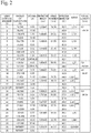
- Fig. 2 depicts data on the respective lenses that construct the lens system 10.
- the radius of curvature (Ri) is the radius of curvature (in mm) of each surface of each lens disposed in order from the object side 11, the distance di is the distance (in mm) between the respective lens surfaces, the effective diameter (Di) is the effective diameter of each lens surface (or "diameter” in mm), the refractive index nd is the refractive index (d-line) of each lens, and the Abbe number vd is the Abbe number (d-line) of each lens.
- the surfaces that have a surface number marked with an asterisk are aspherical surfaces, and the lenses whose lens names have been marked with an asterisk are lenses that use anomalous dispersion glass. The same applies to the embodiments described later.
- Fig. 3 depicts coefficients of the aspherical surfaces included in the lens system 10.
- the surface S1 on the object side 11 of the lens L11 closest to the object side 11 of the first lens group G1 and the surface S26 on the image plane side of the lens L45 of the fourth lens group G4 are aspherical.
- the aspherical surfaces it is desirable for the aspherical surfaces to be surfaces located inside the lens system 10.
- the surface S1 on the object side 11 of the lens L11 positioned closest to the object side 11 has the largest effective diameter, which means that asphericalization has a large effect. Accordingly, this surface is suited to stably and favorably correcting aberration.
- Fig. 4 depicts the values of the focal distance f, the F No., the angle of view, and the variable distances d10 and d12 in the lens system 10 when the focal length of the lens system 10 is at infinity, at an intermediate position (1800 mm), and at the nearest distance (shortest position, 145 mm).
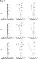
- Fig. 5 depicts spherical aberration, astigmatism, and distortion for when the focal length of the lens system 10 is at infinity ( Fig. 5(a) ), at an intermediate position (1800 mm) ( Fig. 5(b) ), and at the shortest position (nearest distance, 145 mm) ( Fig. 5(c) ).
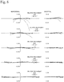
- Fig. 6 depicts the transverse aberration at infinity.
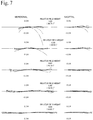
- Fig. 7 depicts the transverse aberration at an intermediate position (1800 mm)
- Fig. 8 depicts the transverse aberration at the shortest position (nearest distance, 145 mm).
- Spherical aberration is shown for the wavelengths of 404.6560 nm (dot-dash line), 435.8340 nm (dashed line), 486.1330 nm (dotted line, short dashed line), 546.0740 nm (dot-dot-dash line), 587.5620 nm (short dot-dash line), and 656.2720 nm (solid line).
- Astigmatism is depicted for meridional (tangential) rays M and sagittal rays Sa. The same applies to the aberration diagrams described later.
- the lens system 10 depicted in these drawings is composed of a total of 15 lenses (L11 to L15, L21, L31 to L33, and L41 to L46).
- the first lens group G1 disposed closest to the object side 11 has a five-lens configuration that includes, in order from the object side 11, a meniscus lens (first meniscus lens) L11 that has negative refractive power and is convex on the object side 11, the biconcave negative lens L12, the meniscus lens (second meniscus lens) L13 that has negative refractive power and is convex on the object side 11, a biconvex positive lens L14, and a meniscus lens L15 that has negative refractive power and is concave on the object side 11.
- the second lens group G2 which is the focusing lens group, has a single-lens configuration composed of the positive meniscus lens L21 that is concave on the object side 11.
- the third lens group G3 is composed, in order from the object side 11, of the biconvex positive lens L31 and a cemented lens B31 composed of the biconvex positive lens L32 and the negative meniscus lens L33 that is concave on the object side 11.
- the fourth lens group G4 which is disposed on the image plane side 12 of the third lens group G3 with the stop St in between and is closest to the image plane side 12 (the most of the image plane side 12), is composed of the cemented lens B41, which is made up of the biconcave negative lens L41 and the positive meniscus lens L42 that is convex on the object side 11, the cemented lens B42 that is composed of a negative meniscus lens L43 that is convex on the object side 11 and a biconvex positive lens L44, the negative meniscus lens L45 that is concave on the object side 11, and the positive meniscus lens L46 that is concave on the object side 11.
- the lens system 10 depicted in Fig. 1 includes all of the configurations described above, and the values of the respective conditions are as follows.
- G 1 f / G 2 f ⁇ 0.12 E 1 ⁇ E 2 : 0.4 / 13.9
- G 3 LSH / G 3 LSr D 17 / 2 / R 17 0.02
- the lens system 10 depicted in Fig. 1 satisfies all of Conditions (1) to (5), and is a lens system that has a focal length of 29 mm, is wide angle with an angle of view of 36.8 degrees, and is extremely bright with an F number of 1.69.
- the lens system 10 when focusing from infinity to the near distance, the F number is fixed, the focal length and the angle of view hardly change, and there are hardly any fluctuations in magnification, which means that it is possible to easily perform focusing and obtain images that are sharp and have little fluctuations in brightness at the desired focal position.
- Fig. 9 depicts a different lens system 10.
- Fig. 9(a) depicts the lens arrangement when the focus position is at infinity
- Fig. 9(b) depicts the lens arrangement when the focus position is the shortest position (nearest distance, 150 mm).
- This lens system 10 is also composed of a total of 15 lenses (L11 to L15, L21, L31 to L33, and L41 to L46), and includes, in order from the object side 11, a first lens group G1 that is fixed during focusing and has negative refractive power, a second lens group G2 that has positive refractive power and moves during focusing, a third lens group G3 that has positive refractive power and is fixed during focusing, and a fourth lens group G4 that has a stop St disposed on the object side 11, has positive refractive power, and is fixed during focusing.
- this lens system 10 is also a retrofocus type with a negative-positive-positive-positive four-group configuration, and is an inner-focus system where only the second lens group G2 moves along the optical axis 7 during focusing.
- the lens system also has the stop St disposed between the third lens group G3 and the fourth lens group G4 that are fixed.
- the second lens group G2 has a single lens configuration composed of a positive meniscus lens L21 that is concave on the object side 11, and moves monotonously from the object side 11 to the image plane side 12 when focusing from infinity to a near distance.
- Fig. 10 depicts data on each lens that configures the lens system 10.
- Fig. 11 depicts coefficients of the aspherical surfaces included in the lens system 10.
- Fig. 12 depicts the focal length f, the F number (F No.), the angle of view, and the values of the variable distances d10 and d12 of the lens system 10 when the focal length of the lens system 10 is at infinity, at an intermediate position (1800 mm), and at the nearest distance (150 mm).
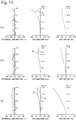
- Fig. 13 depicts spherical aberration, astigmatism, and distortion when the focal length of the lens system 10 is at infinity ( Fig. 13(a) ), at an intermediate position (1800 mm) ( Fig. 13(b) ), and at the nearest distance (150 mm) ( Fig. 13(c) ).
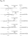
- Figs. 14 to 16 depict transverse aberration at infinity, at an intermediate position (1800 mm), and at the nearest distance (150 mm).
- the first lens group G1 that is closest to the object side has a five-lens configuration that includes, in order from the object side 11, a meniscus lens (first meniscus lens) L11 that has negative refractive power and is convex on the object side 11, a meniscus lens (second meniscus lens) L12 that has negative refractive power and is convex on the object side 11, a biconcave negative lens L13, a biconvex positive lens L14, and a meniscus lens L15 that has negative refractive power and is concave on the object side 11.
- the second meniscus lens and the negative lens are interchanged, so that the first distance E1 is the distance along the optical axis 7 between the edge of the image plane side 12 surface of the second meniscus lens L12 and the edge of the object side surface of the negative lens L13 and the second distance E2 is the distance between the edge of the image plane side 12 surface of the first meniscus lens L11 and the object side 11 surface of the second meniscus lens L12.
- the rest of the configuration of the first lens group G1 and the configurations of the other lens groups G2 to G4 are the same as in the lens system 10 depicted in Fig. 1 .
- the lens system 10 depicted in Fig. 9 also satisfies all of Conditions (1) to (5) and is a lens system that has a focal length of 29 mm, is wide angle with an angle of view of 36.8 degrees, and is extremely bright with an F number of 1.68.
- the F number is fixed, the focal length and the angle of view hardly change, and there are hardly any fluctuations in magnification, which means that it is possible to easily perform focusing and obtain images that are sharp and have little fluctuations in brightness at the desired focal position.
- Figs. 13 to 16 it is possible to acquire images in which various aberrations are favorably corrected across the entire focusing range.
- Fig. 17 depicts yet another lens system 10.
- Fig. 17(a) depicts the lens arrangement when the focus position is at infinity
- Fig. 17(b) depicts the lens arrangement when the focus position is the nearest distance (190 mm).
- This lens system 10 is also composed of a total of 15 lenses (L11 to L15, L21, L31 to L33, and L41 to L46), and includes, in order from the object side 11, a first lens group G1 that has negative refractive power and is fixed during focusing, a second lens group G2 that has positive refractive power and moves during focusing, a third lens group G3 that has positive refractive power and is fixed during focusing, and a fourth lens group G4 that has a stop St disposed on the object side 11, has positive refractive power, and is fixed during focusing.
- this lens system 10 is also a retrofocus type with a negative-positive-positive-positive four-group configuration, and is an inner-focus system where only the second lens group G2 moves along the optical axis 7 during focusing.
- the lens system has the stop St disposed between the third lens group G3 and the fourth lens group G4 that are fixed.
- the second lens group G2 has a single-lens configuration composed of a positive meniscus lens L21 that is concave on the object side 11 and moves monotonously from the object side 11 to the image plane side 12 when focusing from infinity to a near distance.
- Fig. 18 depicts data on each lens that constructs the lens system 10.
- Fig. 19 depicts coefficients of the aspherical surfaces included in the lens system 10.
- Fig. 20 depicts the focal length f, the F number (F No.), the angle of view, and the values of the variable distances d10 and d12 of the lens system 10 when the focal length of the lens system 10 is at infinity, at an intermediate position (2000 mm), and at the nearest distance (190 mm).
- Fig. 21 depicts spherical aberration, astigmatism, and distortion when the focal length of the lens system 10 is at infinity ( Fig. 21(a) ), at an intermediate position (2000 mm) ( Fig. 21(b) ), and at the nearest distance (190 mm) ( Fig. 21(c) ).
- Figs. 22 to 24 depict transverse aberration at infinity, at an intermediate position (2000 mm), and at the nearest distance (190 mm).
- the first lens group G1 closest to the object side is the same as the lens system 10 depicted in Fig. 9
- the rest of the configuration of the first lens group G1 and the configurations of the other lens groups G2 to G4 are the same as the lens system 10 depicted in Fig. 1 .
- the lens system 10 depicted in Fig. 17 satisfies Conditions (1) to (3) and (5).
- Condition (4) the surface S21 on the image plane side 12 of the cemented lens B41 is too close to flat, resulting in a tendency for the aberration correction performance to be somewhat insufficient.
- aberrations such as coma aberration are corrected to a favorable range by disposing more anomalous dispersion lenses at important positions, such as both lenses that construct the cemented lens B42.
- This lens system 10 is also a lens system that has a focal length of 29 mm, is wide angle with an angle of view of 36.8 degrees, and is extremely bright with an F number of 1.66.
- the lens system 10 when focusing from infinity to the near distance, the F number is fixed, the focal length and the angle of view hardly change, and there are hardly any fluctuations in magnification, which means that it is possible to easily perform focusing and obtain images that are sharp and have little fluctuations in brightness at the desired focal position.
- Figs. 21 to 25 it is possible to acquire images in which various aberrations are favorably corrected across the entire focusing range.
Landscapes
- Physics & Mathematics (AREA)
- General Physics & Mathematics (AREA)
- Optics & Photonics (AREA)
- Nonlinear Science (AREA)
- Lenses (AREA)
Applications Claiming Priority (3)
| Application Number | Priority Date | Filing Date | Title |
|---|---|---|---|
| JP2017253611 | 2017-12-28 | ||
| JP2017253610 | 2017-12-28 | ||
| PCT/JP2018/047816 WO2019131748A1 (fr) | 2017-12-28 | 2018-12-26 | Système de lentille et dispositif d'imagerie |
Publications (2)
| Publication Number | Publication Date |
|---|---|
| EP3734344A1 true EP3734344A1 (fr) | 2020-11-04 |
| EP3734344A4 EP3734344A4 (fr) | 2021-08-18 |
Family
ID=67063778
Family Applications (1)
| Application Number | Title | Priority Date | Filing Date |
|---|---|---|---|
| EP18897714.4A Withdrawn EP3734344A4 (fr) | 2017-12-28 | 2018-12-26 | Système de lentille et dispositif d'imagerie |
Country Status (4)
| Country | Link |
|---|---|
| US (1) | US20210072516A1 (fr) |
| EP (1) | EP3734344A4 (fr) |
| JP (1) | JP7148154B2 (fr) |
| WO (1) | WO2019131748A1 (fr) |
Families Citing this family (3)
| Publication number | Priority date | Publication date | Assignee | Title |
|---|---|---|---|---|
| JP7162883B2 (ja) * | 2019-02-07 | 2022-10-31 | 株式会社シグマ | 広角レンズ系 |
| TWI708073B (zh) * | 2019-11-05 | 2020-10-21 | 上暘光學股份有限公司 | 高解析度定焦鏡頭 |
| JP7608069B2 (ja) * | 2020-05-21 | 2025-01-06 | キヤノン株式会社 | 単焦点レンズおよび撮像装置 |
Family Cites Families (13)
| Publication number | Priority date | Publication date | Assignee | Title |
|---|---|---|---|---|
| JP2000098222A (ja) * | 1998-09-18 | 2000-04-07 | Cosina Co Ltd | 投射レンズ |
| JP3579627B2 (ja) | 2000-02-16 | 2004-10-20 | ペンタックス株式会社 | 広角レンズ系 |
| DE10215434B4 (de) | 2002-04-08 | 2015-01-15 | Carl Zeiss | Objektiv und Objektivserie |
| JP4700957B2 (ja) * | 2004-12-02 | 2011-06-15 | 日東光学株式会社 | ズームレンズシステム |
| JP5118584B2 (ja) * | 2008-08-27 | 2013-01-16 | 富士フイルム株式会社 | 投影レンズおよびこれを用いた投写型表示装置 |
| JP5118583B2 (ja) * | 2008-08-27 | 2013-01-16 | 富士フイルム株式会社 | 投影レンズおよびこれを用いた投写型表示装置 |
| JP5118582B2 (ja) * | 2008-08-27 | 2013-01-16 | 富士フイルム株式会社 | 投影レンズおよびこれを用いた投写型表示装置 |
| JP5363084B2 (ja) | 2008-12-01 | 2013-12-11 | 富士フイルム株式会社 | 投写用魚眼レンズおよびこれを用いた投写型表示装置 |
| JP5731176B2 (ja) * | 2010-11-30 | 2015-06-10 | リコー光学株式会社 | 投射用レンズおよび投射型画像表示装置 |
| JP2016038547A (ja) * | 2014-08-11 | 2016-03-22 | 株式会社ニコン | 光学系、該光学系を備えた撮像装置、光学系の製造方法 |
| JP6609956B2 (ja) * | 2015-03-27 | 2019-11-27 | 株式会社シグマ | 魚眼レンズ |
| JP2017209154A (ja) * | 2016-05-23 | 2017-11-30 | オリンパス株式会社 | 内視鏡システム |
| JP6692694B2 (ja) * | 2016-05-25 | 2020-05-13 | 富士フイルム株式会社 | 結像光学系、投写型表示装置、および、撮像装置 |
-
2018
- 2018-12-26 WO PCT/JP2018/047816 patent/WO2019131748A1/fr not_active Ceased
- 2018-12-26 US US16/955,415 patent/US20210072516A1/en not_active Abandoned
- 2018-12-26 EP EP18897714.4A patent/EP3734344A4/fr not_active Withdrawn
- 2018-12-26 JP JP2019562096A patent/JP7148154B2/ja active Active
Also Published As
| Publication number | Publication date |
|---|---|
| JPWO2019131748A1 (ja) | 2020-12-10 |
| US20210072516A1 (en) | 2021-03-11 |
| EP3734344A4 (fr) | 2021-08-18 |
| WO2019131748A1 (fr) | 2019-07-04 |
| JP7148154B2 (ja) | 2022-10-05 |
Similar Documents
| Publication | Publication Date | Title |
|---|---|---|
| US20160252712A1 (en) | Zoom lens system, interchangeable lens device, and camera system | |
| JP5893959B2 (ja) | ズームレンズ | |
| CN103221869B (zh) | 目镜变焦光学系统及光学设备 | |
| US20080062532A1 (en) | Zoom lens and image pickup apparatus | |
| JP2013178410A (ja) | ズームレンズ | |
| CN102289057B (zh) | 变焦镜头及摄像装置 | |
| CN110308545A (zh) | 中距远摄镜头及摄像设备 | |
| US8913328B2 (en) | Four group zoom lens system | |
| EP3734342B1 (fr) | Système de lentilles et dispositif d'imagerie | |
| JPH05150161A (ja) | 変倍レンズ | |
| EP3474058A1 (fr) | Système optique pour capture d'image, et dispositif de capture d'image | |
| EP3474059A1 (fr) | Système optique pour capture d'image, et dispositif de capture d'image | |
| EP3734344A1 (fr) | Système de lentille et dispositif d'imagerie | |
| JP2009037036A (ja) | ズームレンズ及びそれを有する撮像装置 | |
| EP3093700B1 (fr) | Système de lentille objectif | |
| JP2010122536A (ja) | ズームレンズ | |
| US11378788B2 (en) | Zoom lens system and imaging apparatus | |
| JP7504466B2 (ja) | ズームレンズ | |
| JP4585796B2 (ja) | ズームレンズ及びそれを有する撮像装置 | |
| EP3514597A1 (fr) | Système optique pour capture d'image et dispositif de capture d'image | |
| JP4928288B2 (ja) | ズームレンズ及びそれを有する撮像装置 | |
| EP3734343A1 (fr) | Système de lentille et dispositif d'imagerie | |
| JP2020012908A (ja) | ズームレンズ及び撮像装置 | |
| JP2017215407A (ja) | 光学系および光学機器 | |
| JP4366619B2 (ja) | 望遠コンバージョンレンズ |
Legal Events
| Date | Code | Title | Description |
|---|---|---|---|
| STAA | Information on the status of an ep patent application or granted ep patent |
Free format text: STATUS: THE INTERNATIONAL PUBLICATION HAS BEEN MADE |
|
| PUAI | Public reference made under article 153(3) epc to a published international application that has entered the european phase |
Free format text: ORIGINAL CODE: 0009012 |
|
| STAA | Information on the status of an ep patent application or granted ep patent |
Free format text: STATUS: REQUEST FOR EXAMINATION WAS MADE |
|
| 17P | Request for examination filed |
Effective date: 20200626 |
|
| AK | Designated contracting states |
Kind code of ref document: A1 Designated state(s): AL AT BE BG CH CY CZ DE DK EE ES FI FR GB GR HR HU IE IS IT LI LT LU LV MC MK MT NL NO PL PT RO RS SE SI SK SM TR |
|
| AX | Request for extension of the european patent |
Extension state: BA ME |
|
| DAV | Request for validation of the european patent (deleted) | ||
| DAX | Request for extension of the european patent (deleted) | ||
| A4 | Supplementary search report drawn up and despatched |
Effective date: 20210719 |
|
| RIC1 | Information provided on ipc code assigned before grant |
Ipc: G02B 13/04 20060101AFI20210713BHEP Ipc: G02B 9/64 20060101ALI20210713BHEP Ipc: G02B 13/24 20060101ALI20210713BHEP Ipc: G02B 15/22 20060101ALN20210713BHEP |
|
| STAA | Information on the status of an ep patent application or granted ep patent |
Free format text: STATUS: THE APPLICATION IS DEEMED TO BE WITHDRAWN |
|
| 18D | Application deemed to be withdrawn |
Effective date: 20220216 |