EP3734573B1 - Grafischer geschwindigkeitsleistungsmonitor mit flugintervallverwaltung - Google Patents
Grafischer geschwindigkeitsleistungsmonitor mit flugintervallverwaltung Download PDFInfo
- Publication number
- EP3734573B1 EP3734573B1 EP19216183.4A EP19216183A EP3734573B1 EP 3734573 B1 EP3734573 B1 EP 3734573B1 EP 19216183 A EP19216183 A EP 19216183A EP 3734573 B1 EP3734573 B1 EP 3734573B1
- Authority
- EP
- European Patent Office
- Prior art keywords
- speed
- indicator
- depicting
- performance monitor
- target
- Prior art date
- Legal status (The legal status is an assumption and is not a legal conclusion. Google has not performed a legal analysis and makes no representation as to the accuracy of the status listed.)
- Active
Links
Images



Classifications
-
- B—PERFORMING OPERATIONS; TRANSPORTING
- B64—AIRCRAFT; AVIATION; COSMONAUTICS
- B64D—EQUIPMENT FOR FITTING IN OR TO AIRCRAFT; FLIGHT SUITS; PARACHUTES; ARRANGEMENT OR MOUNTING OF POWER PLANTS OR PROPULSION TRANSMISSIONS IN AIRCRAFT
- B64D43/00—Arrangements or adaptations of instruments
- B64D43/02—Arrangements or adaptations of instruments for indicating aircraft speed or stalling conditions
-
- G—PHYSICS
- G08—SIGNALLING
- G08G—TRAFFIC CONTROL SYSTEMS
- G08G5/00—Traffic control systems for aircraft
- G08G5/20—Arrangements for acquiring, generating, sharing or displaying traffic information
- G08G5/21—Arrangements for acquiring, generating, sharing or displaying traffic information located onboard the aircraft
-
- G—PHYSICS
- G06—COMPUTING OR CALCULATING; COUNTING
- G06F—ELECTRIC DIGITAL DATA PROCESSING
- G06F3/00—Input arrangements for transferring data to be processed into a form capable of being handled by the computer; Output arrangements for transferring data from processing unit to output unit, e.g. interface arrangements
- G06F3/14—Digital output to display device ; Cooperation and interconnection of the display device with other functional units
-
- G—PHYSICS
- G08—SIGNALLING
- G08G—TRAFFIC CONTROL SYSTEMS
- G08G5/00—Traffic control systems for aircraft
- G08G5/20—Arrangements for acquiring, generating, sharing or displaying traffic information
- G08G5/25—Transmission of traffic-related information between aircraft
-
- G—PHYSICS
- G08—SIGNALLING
- G08G—TRAFFIC CONTROL SYSTEMS
- G08G5/00—Traffic control systems for aircraft
- G08G5/50—Navigation or guidance aids
- G08G5/53—Navigation or guidance aids for cruising
-
- G—PHYSICS
- G08—SIGNALLING
- G08G—TRAFFIC CONTROL SYSTEMS
- G08G5/00—Traffic control systems for aircraft
- G08G5/50—Navigation or guidance aids
- G08G5/55—Navigation or guidance aids for a single aircraft
Definitions
- CDTI cockpit display of traffic information
- ADS-B technology also enables the development of algorithms and applications which can improve air traffic flow into and out of busy terminal areas.
- One such application is flight deck interval management (FIM), whereby air traffic control (ATC) assigns a time or distance spacing interval (goal), for one aircraft to maintain relative to a designated target aircraft.
- FIM flight deck interval management
- ATC air traffic control
- MOPS Minimum Operational Performance Standards
- FIM Flight Deck Interval Management
- US10074282B1 relates to the display of flight interval management data
- US2014/249701 relates to a system and method for managing an interval between aircraft
- EP3509052A1 relates to safe speed advisories for flight deck interval management paired approach systems.
- embodiments of the inventive concepts disclosed herein are directed to an aircraft system as defined in claim 13.
- a display device as defined in claim 1.
- a method comprising: generating a speed performance monitor graphical user interface (GUI), the speed performance monitor GUI depicting flight deck interval management (FIM) information, the speed performance monitor GUI comprising: an interval management (IM) speed range indicator depicting an IM speed range; an IM speed upper limit indicator depicting an IM speed upper limit and implemented at a first end of the IM speed range indicator; an IM speed lower limit indicator depicting an IM speed lower limit and implemented at a second end of the IM speed range indicator; an IM speed target indicator depicting an IM speed target; and a current speed indicator depicting a current speed relative to the IM speed target; and outputting graphical data associated with the speed performance monitor GUI to a display for presentation to a pilot, optionally wherein the method is carried out using the display device of any of claims 1 to 12.
- GUI speed performance monitor graphical user interface
- FIM flight deck interval management
- inventive concepts are not limited in their application to the details of construction and the arrangement of the components or steps or methodologies set forth in the following description or illustrated in the drawings.
- inventive concepts disclosed herein may be practiced without these specific details.
- well-known features may not be described in detail to avoid unnecessarily complicating the instant disclosure.
- inventive concepts disclosed herein are capable of other embodiments or of being practiced or carried out in various ways. Also, it is to be understood that the phraseology and terminology employed herein is for the purpose of description and should not be regarded as limiting.
- a letter following a reference numeral is intended to reference an embodiment of the feature or element that may be similar, but not necessarily identical, to a previously described element or feature bearing the same reference numeral (e.g., 1, 1a, 1b).
- reference numeral e.g. 1, 1a, 1b
- Such shorthand notations are used for purposes of convenience only, and should not be construed to limit the inventive concepts disclosed herein in any way unless expressly stated to the contrary.
- any reference to "one embodiment,” or “some embodiments” means that a particular element, feature, structure, or characteristic described in connection with the embodiment is included in at least one embodiment of the inventive concepts disclosed herein.
- GUI speed performance monitor graphical user interface
- full integration of a FIM application may be feasible on forward-fit aircraft, whereby the application can be hosted in a main avionics system and interface with existing displays, controls, systems, and applications to attain and maintain the assigned spacing interval.
- the FIM application may be hosted in an electronic flight bag (EFB) or a tablet computing device environment, which may also provide the CDTI function.
- FIM target speeds may have to be input manually by the flight crew to an auto-flight system.
- a small auxiliary display may also be used concerning the visibility of certain information elements in the pilots' forward field of view.
- Airborne Surveillance and Separation Assurance Processing may be configured to limit the interval management (IM) speed for: maximum operating speed; minimum final approach speed; maximum speed for current aircraft configuration; and IM speed upper limit and IM speed lower limit, which may be adjustable at any time by flight crew.
- ASSAP may set the IM Speed Too Low for Current Configuration Status to "Active” when the IM Speed is less than the Minimum Safe Speed for the Current Configuration.
- ASSAP may set the IM Speed Too Low for Current Configuration Status to "Inactive" when the IM Speed is greater than or equal to the Minimum Safe Speed for the Current Configuration.
- ASSAP may evaluate the IM Speed Conformance Monitoring Status on one (1) second intervals starting 11 seconds after the new IM Speed, and ending when Ownship's CAS is within 5 knots of the new IM Speed. In some embodiments, when the IM Speed Mach/CAS selection is computed in Mach, ASSAP may evaluate the IM Speed Conformance Monitoring Status on one (1) second intervals starting 11 seconds after the new IM Speed, and ending when Ownship's Mach is within 0.02 Mach of the new IM Speed.
- CAS IM Speed Mach/calibrated airspeed
- ASSAP may set the IM Speed Conformance Monitoring Status to "Out of Conformance” if Ownship's CAS is more than 5 knots faster than the Expected Speed Change Profile. In some embodiments, when the IM Speed Mach/CAS selection is computed in CAS and when a new IM Speed is greater than Ownship's CAS, ASSAP may set the IM Speed Conformance Monitoring Status to "Out of Conformance” if Ownship's CAS is more than 5 knots slower than the Expected Speed Change Profile.
- ASSAP may set the IM Speed Conformance Monitoring Status to "Out of Conformance” if Ownship's Mach is more than 0.02 Mach faster than the Expected Speed Change Profile.
- ASSAP may set the IM Speed Conformance Monitoring Status to "Out of Conformance” if Ownship's Mach is more than 0.02 Mach slower than the Expected Speed Change Profile.
- the CDTI may provide the IM Speed Change Visual Advisory to the Flight Crew when IM Speed has changed.
- the CDTI may provide an Alert to the Flight Crew, consistent with flight deck philosophy, whenever the IM Speed Too Low for Current Configuration Status is set to "Active.”
- Some embodiments may include a speed performance monitor GUI depicted on a display that may be used during interval management (IM) operations.
- the graphical display may allow a flight crew to monitor the speed performance of an aircraft relative to an assigned target speed, and in conformance with general performance limitations of the aircraft.
- the speed performance monitor GUI may be displayed on any suitable display, such as a multi-function display or touchscreen in a cockpit in a forward-fit aircraft.
- the speed performance monitor GUI may be displayed as part of an auxiliary display, positioned in the pilots' forward field of view.
- the speed performance monitor GUI may be displayed on a mobile display device (e.g., a tablet computing device or an EFB).
- Embodiments may improve the field of aviation by improving safety and improving a pilot's situational awareness of IM operations.
- an exemplary embodiment of a system implemented in an aircraft 100 according to the inventive concepts disclosed herein includes at least one display (e.g., three forward displays of a cockpit, such as two outboard primary flight displays 102 and a center multi-function display 104), a computing device 106 (e.g., a tablet computing device and/or an EFB), at least one user input device 108, at least one avionics computing device (e.g., an avionics server 110), and an ADS-B receiver 118, some or all of which may be communicatively coupled at any given time.
- a display e.g., three forward displays of a cockpit, such as two outboard primary flight displays 102 and a center multi-function display 104
- a computing device 106 e.g., a tablet computing device and/or an EFB
- user input device 108 e.g., a tablet computing device and/or an EFB
- at least one avionics computing device e.g., an avionics
- a cockpit of the aircraft 100 may include a plurality of displays, such as three forward displays configured to present images to flight crew (e.g., pilot(s)).
- Two outboard primary flight displays 102 may be configured to display an attitude director indicator (ADI), a horizontal situation indicator (HSI), and optionally traffic targets, as well as other information.
- a center multi-function display 104 may be configured to generate and/or display a navigation map and optionally traffic targets.
- One or more of the displays 102, 104 (e.g., the center multi-function display 104) may be configured to execute a FIM application configured to manage IM operations for ATC assigned time or distance spacing intervals, for the aircraft 100 to maintain relative to a designated target aircraft.
- execution of the FIM application may manage an IM speed range, an IM speed upper limit, an IM speed lower limit, an IM speed target, a current speed, an acceleration trend, and/or a deceleration trend.
- one or more of the displays 102, 104 e.g., the center multi-function display
- center multi-function display 104 is exemplarily described as being configured to generate and/or display a speed performance monitor GUI, wherein the speed performance monitor GUI depicts FIM information
- other displays e.g., one or more of primary flight displays 102 may be configured as such.
- Each of the displays 102, 104 may be configured to receive graphics data (e.g., graphics commands) and render graphics associated with such graphics data for display to a user (e.g., a pilot). Additionally, the displays 102, 104 may be configured to receive user inputs from the user input device 108 and change a display of content based on the user inputs, such as changing a cursor location.
- Each of the displays 102, 104 may include at least one display 120 (e.g., a display element), at least one processor 122, memory 124, and storage, which may be communicatively coupled.
- the at least one processor 122 may be configured to run various software applications or computer code stored (e.g., maintained) in a non-transitory computer-readable medium (e.g., memory 124 or storage) and configured to execute various instructions or operations, such as operations disclosed throughout.
- a non-transitory computer-readable medium e.g., memory 124 or storage
- a cockpit of the aircraft 100 may include a computing device 106 (e.g., a tablet computing device and/or an EFB).
- the computing device 106 may be configured to execute a FIM application configured to manage IM operations for ATC assigned time or distance spacing intervals, for the aircraft 100 to maintain relative to a designated target aircraft.
- execution of the FIM application may manage an IM speed range, an IM speed upper limit, an IM speed lower limit, an IM speed target, a current speed, an acceleration trend, and/or a deceleration trend.
- the computing device 106 may be configured to generate and/or display a speed performance monitor GUI (e.g., based at least on ADS-B In data associated with ADS-B traffic information from other aircraft in a vicinity of an aircraft), wherein the speed performance monitor GUI depicts FIM information.
- a speed performance monitor GUI e.g., based at least on ADS-B In data associated with ADS-B traffic information from other aircraft in a vicinity of an aircraft
- the computing device 106 may include at least one display 126 (e.g., a display element), at least one processor 128, memory 130, and storage, which may be communicatively coupled.
- the at least one processor 128 may be configured to run various software applications or computer code stored (e.g., maintained) in a non-transitory computer-readable medium (e.g., memory 130 or storage) and configured to execute various instructions or operations, such as operations disclosed throughout.
- the at least one user input device 108 may be configured to receive user inputs from a user (e.g., a pilot) and output user input data to one or more displays (e.g., two outboard primary flight displays 102 and a center multi-function display 104) and/or the avionics server 110.
- the user input device may be configured as a cursor control device.
- the at least one user input device 108 may be implemented as a cursor control device, a mouse, a trackpad, a keyboard, a keypad, a touchscreen, an eye tracking system (e.g., comprising a processor and a sensor), and/or a voice recognition system (e.g., comprising a processor and a microphone).
- the user input device 108 may output user input data to the displays and/or the server 110, which may track user inputs, such as cursor movement and cursor events (e.g., clicks or selections), received from the user input device 108.
- the ADS-B receiver 118 may be configured to receive ADS-B In data associated with ADS-B traffic information from other aircraft and ground vehicles in the vicinity of the aircraft 100.
- the ADS-B traffic information may include detailed information of each other aircraft's position and intent.
- the ADS-B receiver 118 may be configured to output ADS-B In data to the server 110.
- the ADS-B receiver 118 may include a processor, memory, and storage, which may be communicatively coupled.
- the processor may be configured to run various software applications or computer code stored (e.g., maintained) in a non-transitory computer-readable medium (e.g., memory or storage) and configured to execute various instructions or operations.
- the avionics server 110 may include at least one processor 112, memory 114, and storage 116, as well as other components, equipment, and/or devices commonly included in an avionics computing device, all of which may be communicatively coupled to one another.
- the server 110 may be configured to output data to one or more displays (e.g., two outboard primary flight displays 102 and a center multi-function display 104) and/or the computing device 106.
- the server 110 may be configured to receive data from the user input device 108, the computing device 106, one or more displays (e.g., two outboard primary flight displays 102 and a center multi-function display 104), and/or the ADS-B receiver 118.
- the processor 112 may be configured to run various software applications or computer code stored (e.g., maintained) in a non-transitory computer-readable medium (e.g., memory 114 or storage 116) and configured to execute various instructions or operations.
- a non-transitory computer-readable medium e.g., memory 114 or storage 116
- the server 110 or the processor 112 may be implemented as a special purpose computer or a special purpose processor configured (e.g., programmed) to execute instructions for performing any or all of the operations disclosed throughout.
- the system 100 may include any suitable number of servers 110.
- the processor 112 may be configured to execute a FIM application configured to manage IM operations for ATC assigned time or distance spacing intervals, for the aircraft 100 to maintain relative to a designated target aircraft. For example, execution of the FIM application may manage an IM speed range, an IM speed upper limit, an IM speed lower limit, an IM speed target, a current speed, an acceleration trend, and/or a deceleration trend. Additionally, the processor 112 may be configured to generate a speed performance monitor GUI (e.g., based at least on ADS-B In data associated with ADS-B traffic information from other aircraft in a vicinity of an aircraft), wherein the speed performance monitor GUI depicts FIM information.
- a speed performance monitor GUI e.g., based at least on ADS-B In data associated with ADS-B traffic information from other aircraft in a vicinity of an aircraft
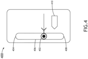
- FIGS. 4-9 exemplary views of the speed performance monitor GUI depicting FIM information are shown. From these embodiments, figures 8 and 9 correspond to the subject matter claimed , while figures 4 to 7B do not fall within the scope of the appended claims.
- the speed performance monitor GUI may include an IM speed range indicator 406 depicting an IM speed range, an IM speed upper limit indicator 404 depicting an IM speed upper limit and implemented at a first end (e.g., a top) of the IM speed range indicator 406, an IM speed lower limit indicator 408 depicting an IM speed lower limit and implemented at a second end (e.g., a bottom) of the IM speed range indicator 406, an IM speed target indicator 402 depicting an IM speed target, and/or a current speed indicator 410 depicting a current speed relative to the IM speed target.
- Such graphical elements may be contained within a rounded rectangular border.
- the IM speed upper limit indicator 404 depicting an IM speed upper limit may be implemented at a first end (e.g., a top) of the IM speed range indicator 406.
- the IM speed upper limit indicator 404 may be implemented as an endcap portion of the IM speed range indicator 406.
- the upper IM speed limit may be set to a maximum speed for the current aircraft configuration (e.g., based on slats, flaps, and/or gear position), or a default IM Speed Upper Limit (e.g., as set by the flight crew).
- the IM speed target exceeds the IM speed upper limit
- the IM speed upper limit indicator 404 may change color and/or flash.
- the IM speed upper limit indicator 404 may change.
- the current speed indicator 410 may depict the aircraft's 100 current speed in relation to the operational airspeed range.
- the difference in vertical position between the current speed indicator 410 and the line and vertex of the chevron portion of the IM speed target indicator 402 chevron portion indicates the current speed delta (difference between current aircraft speed and the target speed).
- the current speed indicator 410 may include a textual depiction of a speed differential between the current speed and the target speed (e.g., if the speed differential exceeds a predetermined speed differential).
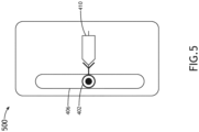
- the current speed indicator 410 includes a pentagonal-shaped outline, wherein two edges of the pentagonal-shaped outline align with the chevron portion of the IM speed target indicator 402 when the current aircraft speed and the target speed match. For example, when the current speed matches the target speed, a nose of the current speed indicator 410 may be positioned within the IM speed target indicator 402 chevron, as shown in FIG. 5 depicting an exemplary view 500 of the speed performance monitor GUI.
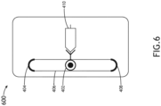
- an exemplary view 600 of the speed performance monitor GUI is shown.
- the ASSAP application should not provide IM speed targets that fall outside the current operational limitations of the aircraft 100.
- the current aircraft configuration and/or limitations are not known to the application.
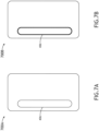
- exemplary views 700A, 700B of the speed performance monitor GUI are shown. Any time the aircraft configuration is changed (flaps/slats/gear extended or retracted), the operational speed range may also change, affecting the upper and lower speed limits. This can result in an instantaneous repositioning of the IM speed target indicator 402 within the IM speed range indicator 406 capsule outline. To advise the pilots that this has occurred, the capsule outline may change color (as shown in FIG. 7B ) (e.g., to cyan) (indicating pilot input to secondary flight controls), and/or flash momentarily.
- an exemplary view 800 of the speed performance monitor GUI including a fast indicator 802 and a deceleration trend indicator 804 is shown.
- the fast indicator 802 may depict that the current speed is fast relative to the IM speed target.
- the fast indicator 802 may appear at the top of the speed performance monitor GUI.
- deceleration trend indicator 804 which may include an arrow, may appear as the aircraft 100 makes a required speed adjustment to re-capture the target speed.
- the deceleration trend indicator 804 may indicate the predicted airspeed at predetermined time ahead (e.g., ten seconds ahead), at the current rate of change of speed.
- FIG. 9 an exemplary view 900 of the speed performance monitor GUI including a slow indicator 904 and an acceleration trend indicator 902 is shown.
- the slow indicator 904 may depict that the current speed is slow relative to the IM speed target.
- the acceleration trend indicator 902, which may include an arrow, may depict an acceleration trend.
- FIG. 9 illustrates the condition whereby the current speed is slow compared to the target speed, and the aircraft 100 is accelerating to match the target speed.
- an exemplary embodiment of a method 1000 may include one or more of the following steps. Some embodiments may include performing one or more steps of the method 1000 iteratively, concurrently, sequentially, and/or non-sequentially. Additionally, for example, some embodiments may include performing one or more instances of the method 1000 iteratively, concurrently, and/or sequentially.
- a step 1002 may include generating a speed performance monitor graphical user interface (GUI), the speed performance monitor GUI depicting flight deck interval management (FIM) information.
- GUI speed performance monitor graphical user interface
- FIM flight deck interval management
- a step 1004 may include outputting graphical data associated with the speed performance monitor GUI to a display for presentation to a pilot.
- the steps 1002 and 1004 may be performed by the at least one processor 112, the at least one processor 122, the at least one processor 128, or some combination thereof.
- method 1000 may include any of the operations disclosed throughout.
- embodiments of the inventive concepts disclosed herein may be directed to a system, device, and a method configured to generate a speed performance monitor GUI depicting FIM information and to output graphical data associated with the generated GUI to a display for presentation to a user (e.g., a pilot).
- a speed performance monitor GUI depicting FIM information
- graphical data associated with the generated GUI to a display for presentation to a user (e.g., a pilot).
- At least one non-transitory computer-readable medium may refer to as at least one non-transitory computer-readable medium (e.g., memory 114, memory 124, memory 130, storage 116, or a combination thereof; e.g., at least one computer-readable medium implemented as hardware; e.g., at least one non-transitory processor-readable medium, at least one memory (e.g., at least one nonvolatile memory, at least one volatile memory, or a combination thereof; e.g., at least one random-access memory, at least one flash memory, at least one read-only memory (ROM) (e.g., at least one electrically erasable programmable read-only memory (EEPROM)), at least one on-processor memory (e.g., at least one on-processor cache, at least one on-processor buffer, at least one on-processor flash memory, at least one on-processor EEPROM, or a combination thereof),
- ROM read-only memory
- EEPROM electrically
- At least one means one or a plurality of; for example, “at least one” may comprise one, two, three, ..., one hundred, or more.
- one or more means one or a plurality of; for example, “one or more” may comprise one, two, three, ..., one hundred, or more.
- zero or more means zero, one, or a plurality of; for example, “zero or more” may comprise zero, one, two, three, ..., one hundred, or more.
- the methods, operations, and/or functionality disclosed may be implemented as sets of instructions or software readable by a device. Further, it is understood that the specific order or hierarchy of steps in the methods, operations, and/or functionality disclosed are examples of exemplary approaches. Based upon design preferences, it is understood that the specific order or hierarchy of steps in the methods, operations, and/or functionality can be rearranged while remaining within the scope of the inventive concepts disclosed herein.
- the accompanying claims may present elements of the various steps in a sample order, and are not necessarily meant to be limited to the specific order or hierarchy presented.
- embodiments of the methods according to the inventive concepts disclosed herein may include one or more of the steps described herein. Further, such steps may be carried out in any desired order and two or more of the steps may be carried out simultaneously with one another. Two or more of the steps disclosed herein may be combined in a single step, and in some embodiments, one or more of the steps may be carried out as two or more sub-steps. Further, other steps or sub-steps may be carried in addition to, or as substitutes to one or more of the steps disclosed herein.
- inventive concepts disclosed herein are well adapted to carry out the objects and to attain the advantages mentioned herein as well as those inherent in the inventive concepts disclosed herein. While presently preferred embodiments of the inventive concepts disclosed herein have been described for purposes of this disclosure, it will be understood that numerous changes may be made which will readily suggest themselves to those skilled in the art and which are accomplished within the broad scope and coverage of the inventive concepts disclosed and claimed herein.
Landscapes
- Engineering & Computer Science (AREA)
- Aviation & Aerospace Engineering (AREA)
- Physics & Mathematics (AREA)
- General Physics & Mathematics (AREA)
- Theoretical Computer Science (AREA)
- Human Computer Interaction (AREA)
- General Engineering & Computer Science (AREA)
- Traffic Control Systems (AREA)
Claims (14)
- Anzeigevorrichtung, umfassend:eine Anzeige (102, 104), die zum Präsentieren von Bildern für einen Piloten konfiguriert ist;mindestens einen Prozessor (122), der kommunikativ mit der Anzeige gekoppelt ist, wobei der mindestens eine Prozessor zu Folgendem konfiguriert ist:
Erzeugen einer grafischen Benutzeroberfläche (graphical user interface - GUI) für die Geschwindigkeitsleistungsüberwachung, wobei die Geschwindigkeitsleistungsüberwachungs-GUI Informationen zur Cockpit-Intervall-Verwaltung (flight deck interval management - FIM) abbildet, wobei die Geschwindigkeitsleistungsüberwachungs-GUI Folgendes umfasst:einen Indikator (406) des Geschwindigkeitsbereichs für die Intervallverwaltung (IM), der einen IM-Geschwindigkeitsbereich abbildet;einen Indikator (404) des oberen IM-Geschwindigkeitsgrenzwerts, der einen oberen IM-Geschwindigkeitsgrenzwert abbildet und an einem ersten Ende des IM-Geschwindigkeitsbereichsindikators implementiert ist;einen Indikator (408) des unteren IM-Geschwindigkeitsgrenzwerts, der einen unteren IM-Geschwindigkeitsgrenzwert abbildet und an einem zweiten Ende des IM-Geschwindigkeitsbereichsindikators implementiert ist;einen IM-Zielgeschwindigkeitsindikator (402), der eine IM-Zielgeschwindigkeit abbildet; undeinen Indikator (410) der aktuellen Geschwindigkeit, der die aktuelle Geschwindigkeit relativ zu der IM-Zielgeschwindigkeit abbildet; wobei die Anzeigevorrichtung dadurch gekennzeichnet ist, dass die Geschwindigkeitsleistungsüberwachungs-GUI ferner mindestens einen von einem Beschleunigungstrendindikator (902) oder einem Entschleunigungstrendindikator (804) umfasst, wobei der Beschleunigungstrendindikator einen Beschleunigungstrend der aktuellen Geschwindigkeit abbildet, der Entschleunigungstrendindikator einen Entschuldigungstrend der aktuellen Geschwindigkeit abbildet; undwobei der Prozessor ferner zum Ausgeben von der Geschwindigkeitsleistungsüberwachungs-GUI zugeordneten grafischen Daten an die Anzeige zur Präsentation für den Piloten konfiguriert ist. - Vorrichtung nach Anspruch 1, wobei die Geschwindigkeitsleistungsüberwachungs-GUI ferner einen Schnell-Indikator (802) oder einen Langsam-Indikator (904) umfasst, wobei der Schnell-Indikator (802) abbildet, dass die aktuelle Geschwindigkeit relativ zu der IM-Zielgeschwindigkeit schnell ist, der Langsam-Indikator abbildet, dass die aktuelle Geschwindigkeit relativ zu der IM-Zielgeschwindigkeit langsam ist.
- Vorrichtung nach Anspruch 1 oder 2, wobei der Beschleunigungstrendindikator oder der Entschleunigungstrendindikator einen Pfeil umfasst.
- Vorrichtung nach einem der vorhergehenden Ansprüche, wobei die Geschwindigkeitsleistungsüberwachungs-GUI ferner einen abgerundeten rechteckigen Rahmen umfasst, der den IM-Zielgeschwindigkeitsindikator (402), den Indikator (404) des oberen IM-Geschwindigkeitsgrenzwerts, den IM-Geschwindigkeitsbereichsindikator, den Indikator (408) des unteren IM-Geschwindigkeitsgrenzwerts und den Indikator (410) der aktuellen Geschwindigkeit umgibt, wobei der abgerundete rechteckige Rahmen optional eine erste Farbe aufweist, wenn die Geschwindigkeitsleistungsüberwachungs-GUI aktiv ist, und eine andere Farbe, wenn die Geschwindigkeitsleistungsüberwachungs-GUI inaktiv ist.
- Vorrichtung nach einem der vorhergehenden Ansprüche, wobei der Indikator (404) des oberen IM-Geschwindigkeitsgrenzwerts auf eine Höchstgeschwindigkeit für eine aktuelle Luftfahrzeugkonfiguration oder eine Vorgabe für den oberen IM-Geschwindigkeitsgrenzwert eingestellt ist, wobei der Indikator (408) des unteren IM-Geschwindigkeitsgrenzwerts auf eine Mindestmanövriergeschwindigkeit des Luftfahrzeugs oder eine Vorgabe für den unteren IM-Geschwindigkeitsgrenzwert eingestellt ist.
- Vorrichtung nach einem der vorhergehenden Ansprüche, wobei der Indikator (410) der aktuellen Geschwindigkeit eine textuelle Abbildung eines Geschwindigkeitsunterschieds zwischen der aktuellen Geschwindigkeit und der Zielgeschwindigkeit umfasst.
- Vorrichtung nach einem der vorhergehenden Ansprüche, wobei der Indikator (410) der aktuellen Geschwindigkeit eine textuelle Abbildung eines Geschwindigkeitsunterschieds zwischen der aktuellen Geschwindigkeit und der Zielgeschwindigkeit umfasst, wenn der Geschwindigkeitsunterschied einen vorbestimmten Geschwindigkeitsunterschied überschreitet.
- Vorrichtung nach einem der vorhergehenden Ansprüche, wobei der Indikator (410) der aktuellen Geschwindigkeit ferner einen fünfeckförmigen Umriss umfasst.
- Vorrichtung nach einem der vorhergehenden Ansprüche, wobei mindestens ein Abschnitt des IM-Zielgeschwindigkeitsindikators (402) blinkt, wenn sich ein Zielgeschwindigkeitswert ändert.
- Vorrichtung nach einem der vorhergehenden Ansprüche, wobei der IM-Zielgeschwindigkeitsindikator (402) kapselförmig ist, wobei jeder von dem Indikator (404) des oberen IM-Geschwindigkeitsgrenzwerts und dem Indikator (408) des unteren IM-Geschwindigkeitsgrenzwerts einen Endkappenabschnitt beinhaltet.
- Vorrichtung nach einem der vorhergehenden Ansprüche, wobei mindestens einer von dem Indikator des oberen IM-Geschwindigkeitsgrenzwerts und dem Indikator des unteren IM-Geschwindigkeitsgrenzwerts die Farbe ändert, wenn die IM-Zielgeschwindigkeit einen von dem oberen IM-Geschwindigkeitsgrenzwert und dem unteren IM-Geschwindigkeitsgrenzwert überschreitet.
- Vorrichtung nach einem der vorhergehenden Ansprüche, wobei sich mindestens einer von dem Indikator (404) des oberen IM-Geschwindigkeitsgrenzwerts, dem Indikator (408) des unteren IM-Geschwindigkeitsgrenzwerts und dem IM-Geschwindigkeitsbereichsindikator (406) ändert, wenn sich eine Luftfahrzeugkonfiguration ändert, wobei der IM-Geschwindigkeitsbereichsindikator (406) optional die Farbe ändert oder blinkt, wenn sich die Luftfahrzeugkonfiguration ändert.
- Luftfahrzeugsystem, umfassend die Anzeigevorrichtung nach einem der vorhergehenden Ansprüche.
- Verfahren, umfassend:
Erzeugen einer grafischen Benutzeroberfläche (GUI) für die Geschwindigkeitsleistungsüberwachung, wobei die Geschwindigkeitsleistungsüberwachungs-GUI Informationen zur Cockpit-Intervall-Verwaltung (FIM) abbildet, wobei die Geschwindigkeitsleistungsüberwachungs-GUI Folgendes umfasst:einen Indikator (406) des Geschwindigkeitsbereichs für die Intervallverwaltung (IM), der einen IM-Geschwindigkeitsbereich abbildet;einen Indikator (404) des oberen IM-Geschwindigkeitsgrenzwerts, der einen oberen IM-Geschwindigkeitsgrenzwert abbildet und an einem ersten Ende des IM-Geschwindigkeitsbereichsindikators implementiert ist;einen Indikator (408) des unteren IM-Geschwindigkeitsgrenzwerts, der einen unteren IM-Geschwindigkeitsgrenzwert abbildet und an einem zweiten Ende des IM-Geschwindigkeitsbereichsindikators implementiert ist;einen IM-Zielgeschwindigkeitsindikator (402), der eine IM-Zielgeschwindigkeit abbildet; undeinen Indikator (410) der aktuellen Geschwindigkeit, der die aktuelle Geschwindigkeit relativ zu der IM-Zielgeschwindigkeit abbildet; undAusgeben von der Geschwindigkeitsleistungsüberwachungs-GUI zugeordneten grafischen Daten an eine Anzeige zur Präsentation für einen Piloten, wobei das Verfahren optional unter Verwendung der Anzeigevorrichtung nach einem der Ansprüche 1 bis 12 durchgeführt wird.
Applications Claiming Priority (1)
| Application Number | Priority Date | Filing Date | Title |
|---|---|---|---|
| US16/397,113 US11787558B2 (en) | 2019-04-29 | 2019-04-29 | Flight interval management graphical speed performance monitor |
Publications (2)
| Publication Number | Publication Date |
|---|---|
| EP3734573A1 EP3734573A1 (de) | 2020-11-04 |
| EP3734573B1 true EP3734573B1 (de) | 2024-08-14 |
Family
ID=68917364
Family Applications (1)
| Application Number | Title | Priority Date | Filing Date |
|---|---|---|---|
| EP19216183.4A Active EP3734573B1 (de) | 2019-04-29 | 2019-12-13 | Grafischer geschwindigkeitsleistungsmonitor mit flugintervallverwaltung |
Country Status (2)
| Country | Link |
|---|---|
| US (1) | US11787558B2 (de) |
| EP (1) | EP3734573B1 (de) |
Families Citing this family (3)
| Publication number | Priority date | Publication date | Assignee | Title |
|---|---|---|---|---|
| US12361834B2 (en) * | 2020-02-03 | 2025-07-15 | Honeywell International Inc. | Display of traffic information |
| US11705011B2 (en) | 2021-02-16 | 2023-07-18 | Rockwell Collins, Inc. | Assigned spacing to visual separation auto transition |
| US20220306313A1 (en) * | 2021-03-23 | 2022-09-29 | Garmin International, Inc. | Flight deck system for determining aircraft operating constraints |
Family Cites Families (20)
| Publication number | Priority date | Publication date | Assignee | Title |
|---|---|---|---|---|
| FR2748145B1 (fr) * | 1996-04-30 | 1998-07-10 | Sextant Avionique | Procede et dispositif d'entree et de controle de donnees de vol |
| US6828922B1 (en) * | 1998-02-09 | 2004-12-07 | Honeywell International Inc. | Synthetic airborne hazard display |
| US6199008B1 (en) * | 1998-09-17 | 2001-03-06 | Noegenesis, Inc. | Aviation, terrain and weather display system |
| US6650972B1 (en) * | 2000-05-26 | 2003-11-18 | Aerotech Research (U.S.A.), Inc. | Estimation, transmission, receipt, and presentation of vehicle specific environmental conditions and hazards information |
| US7312725B2 (en) * | 2003-07-08 | 2007-12-25 | Supersonic Aerospace International, Llc | Display system for operating a device with reduced out-the-window visibility |
| US7467031B2 (en) * | 2004-12-14 | 2008-12-16 | Honeywell International Inc. | Inflight graphical display of meteorological phenomena and method therefor |
| GB2440958A (en) * | 2006-08-15 | 2008-02-20 | Tomtom Bv | Method of correcting map data for use in navigation systems |
| FR2908218B1 (fr) * | 2006-11-07 | 2014-08-15 | Thales Sa | Dispositif d'aide a la navigation d'un aeronef dans une zone aeroportuaire |
| US8718931B2 (en) * | 2007-10-31 | 2014-05-06 | The Boeing Company | Method and apparatus for cross checking required navigation performance procedures |
| US20140249701A1 (en) * | 2013-03-04 | 2014-09-04 | Honeywell International Inc. | System and method for managing an interval between aircraft |
| US9714081B1 (en) * | 2013-08-29 | 2017-07-25 | Rockwell Collins, Inc. | System and method for avionics integrity and protection |
| WO2016035002A1 (en) * | 2014-09-03 | 2016-03-10 | University Of Malta | A human machine interface device for aircraft |
| US10242579B2 (en) * | 2016-06-13 | 2019-03-26 | Honeywell International Inc. | Systems and methods for situational awareness of current and future vehicle state |
| US10074282B1 (en) | 2017-07-31 | 2018-09-11 | The Boeing Company | Display of flight interval management data |
| US10783288B1 (en) * | 2017-08-08 | 2020-09-22 | Architecture Technology Corporation | System and method for predicting aircraft runway capacity |
| US10690554B2 (en) * | 2017-10-17 | 2020-06-23 | Sikorsky Aircraft Corporation | Composite airspeed indicator display for compound aircrafts |
| US10446040B2 (en) | 2018-01-05 | 2019-10-15 | Honeywell International Inc. | Safe speed advisories for flight deck interval management (FIM) paired approach (PA) systems |
| US10883851B2 (en) * | 2018-09-17 | 2021-01-05 | Honeywell International Inc. | Systems and methods for dynamic readouts for primary flight displays |
| US10957207B2 (en) * | 2018-09-27 | 2021-03-23 | Honeywell International Inc. | Systems and methods for associating critical flight reference data with a flight path vector symbol |
| US20200340827A1 (en) * | 2019-04-26 | 2020-10-29 | Garmin International, Inc. | Impossible turn indication system |
-
2019
- 2019-04-29 US US16/397,113 patent/US11787558B2/en active Active
- 2019-12-13 EP EP19216183.4A patent/EP3734573B1/de active Active
Also Published As
| Publication number | Publication date |
|---|---|
| US20200339275A1 (en) | 2020-10-29 |
| EP3734573A1 (de) | 2020-11-04 |
| US11787558B2 (en) | 2023-10-17 |
Similar Documents
| Publication | Publication Date | Title |
|---|---|---|
| US9234982B2 (en) | Aircraft systems and methods for displaying weather information along a flight path | |
| US10170010B1 (en) | Display of traffic overlaid on aeronautical chart | |
| EP2993655B1 (de) | Flugzeugsysteme und verfahren zur anzeige von abstandsinformationen | |
| US9499279B2 (en) | System and method for displaying runway approach information | |
| EP3321634B1 (de) | System und verfahren zur anzeige von landebahnüberschreitungsinformationen | |
| CA2679910C (en) | Aircraft-centered ground maneuvering monitoring and alerting system | |
| EP3118838B1 (de) | Flugzeugsysteme und verfahren zur überwachung von benachbartem verkehr | |
| EP3012590B1 (de) | System und verfahren zur anzeige von landebahnanfluginformationen | |
| US8203465B2 (en) | Filtering aircraft traffic for display to a pilot | |
| US9135829B2 (en) | Distance separation criteria indicator | |
| EP2775469B1 (de) | System und Verfahren zur Verwaltung eines Intervalls zwischen Flugzeugen | |
| EP3166092A1 (de) | Flugzeugsysteme und verfahren mit verbesserter cpdlc-nachrichtenverwaltung | |
| EP2899509A1 (de) | System und Verfahren zum Anzeigen von Flugbahninformationen in einem Drehflügler | |
| EP2980772B1 (de) | System und verfahren zur automatischen identifizierung von angezeigtem, von der flugsicherung erwähntem verkehr | |
| EP3079138A2 (de) | Flugzeugsysteme und verfahren zum anzeigen einer verbesserten landebahnbeleuchtung | |
| US9340282B2 (en) | System and method for displaying vertical reference on a rotorcraft system | |
| EP3734573B1 (de) | Grafischer geschwindigkeitsleistungsmonitor mit flugintervallverwaltung | |
| EP2849168A1 (de) | System und Verfahren zum Anzeigen von ITP-Zuteilungen auf einer Flugzeugcockpitanzeige | |
| CN105513430B (zh) | 图形化显示邻近旋翼飞行器的系统和方法 | |
| EP3920162A1 (de) | Flugzeugsystem und verfahren zur bereitstellung einer grafischen schwellenanzeige | |
| EP3567567B1 (de) | Systeme und verfahren zur dynamischen implementierung von erhöhten gleitneigungswinkeln in anflugverfahren |
Legal Events
| Date | Code | Title | Description |
|---|---|---|---|
| PUAI | Public reference made under article 153(3) epc to a published international application that has entered the european phase |
Free format text: ORIGINAL CODE: 0009012 |
|
| STAA | Information on the status of an ep patent application or granted ep patent |
Free format text: STATUS: THE APPLICATION HAS BEEN PUBLISHED |
|
| AK | Designated contracting states |
Kind code of ref document: A1 Designated state(s): AL AT BE BG CH CY CZ DE DK EE ES FI FR GB GR HR HU IE IS IT LI LT LU LV MC MK MT NL NO PL PT RO RS SE SI SK SM TR |
|
| AX | Request for extension of the european patent |
Extension state: BA ME |
|
| STAA | Information on the status of an ep patent application or granted ep patent |
Free format text: STATUS: REQUEST FOR EXAMINATION WAS MADE |
|
| 17P | Request for examination filed |
Effective date: 20210504 |
|
| RBV | Designated contracting states (corrected) |
Designated state(s): AL AT BE BG CH CY CZ DE DK EE ES FI FR GB GR HR HU IE IS IT LI LT LU LV MC MK MT NL NO PL PT RO RS SE SI SK SM TR |
|
| STAA | Information on the status of an ep patent application or granted ep patent |
Free format text: STATUS: EXAMINATION IS IN PROGRESS |
|
| 17Q | First examination report despatched |
Effective date: 20220920 |
|
| GRAP | Despatch of communication of intention to grant a patent |
Free format text: ORIGINAL CODE: EPIDOSNIGR1 |
|
| STAA | Information on the status of an ep patent application or granted ep patent |
Free format text: STATUS: GRANT OF PATENT IS INTENDED |
|
| INTG | Intention to grant announced |
Effective date: 20240315 |
|
| GRAS | Grant fee paid |
Free format text: ORIGINAL CODE: EPIDOSNIGR3 |
|
| GRAA | (expected) grant |
Free format text: ORIGINAL CODE: 0009210 |
|
| STAA | Information on the status of an ep patent application or granted ep patent |
Free format text: STATUS: THE PATENT HAS BEEN GRANTED |
|
| AK | Designated contracting states |
Kind code of ref document: B1 Designated state(s): AL AT BE BG CH CY CZ DE DK EE ES FI FR GB GR HR HU IE IS IT LI LT LU LV MC MK MT NL NO PL PT RO RS SE SI SK SM TR |
|
| REG | Reference to a national code |
Ref country code: GB Ref legal event code: FG4D |
|
| REG | Reference to a national code |
Ref country code: CH Ref legal event code: EP |
|
| REG | Reference to a national code |
Ref country code: DE Ref legal event code: R096 Ref document number: 602019056929 Country of ref document: DE |
|
| REG | Reference to a national code |
Ref country code: IE Ref legal event code: FG4D |
|
| REG | Reference to a national code |
Ref country code: LT Ref legal event code: MG9D |
|
| REG | Reference to a national code |
Ref country code: NL Ref legal event code: MP Effective date: 20240814 |
|
| PG25 | Lapsed in a contracting state [announced via postgrant information from national office to epo] |
Ref country code: NO Free format text: LAPSE BECAUSE OF FAILURE TO SUBMIT A TRANSLATION OF THE DESCRIPTION OR TO PAY THE FEE WITHIN THE PRESCRIBED TIME-LIMIT Effective date: 20241114 |
|
| REG | Reference to a national code |
Ref country code: AT Ref legal event code: MK05 Ref document number: 1714054 Country of ref document: AT Kind code of ref document: T Effective date: 20240814 |
|
| PG25 | Lapsed in a contracting state [announced via postgrant information from national office to epo] |
Ref country code: NL Free format text: LAPSE BECAUSE OF FAILURE TO SUBMIT A TRANSLATION OF THE DESCRIPTION OR TO PAY THE FEE WITHIN THE PRESCRIBED TIME-LIMIT Effective date: 20240814 Ref country code: PL Free format text: LAPSE BECAUSE OF FAILURE TO SUBMIT A TRANSLATION OF THE DESCRIPTION OR TO PAY THE FEE WITHIN THE PRESCRIBED TIME-LIMIT Effective date: 20240814 Ref country code: FI Free format text: LAPSE BECAUSE OF FAILURE TO SUBMIT A TRANSLATION OF THE DESCRIPTION OR TO PAY THE FEE WITHIN THE PRESCRIBED TIME-LIMIT Effective date: 20240814 Ref country code: PT Free format text: LAPSE BECAUSE OF FAILURE TO SUBMIT A TRANSLATION OF THE DESCRIPTION OR TO PAY THE FEE WITHIN THE PRESCRIBED TIME-LIMIT Effective date: 20241216 Ref country code: GR Free format text: LAPSE BECAUSE OF FAILURE TO SUBMIT A TRANSLATION OF THE DESCRIPTION OR TO PAY THE FEE WITHIN THE PRESCRIBED TIME-LIMIT Effective date: 20241115 |
|
| PG25 | Lapsed in a contracting state [announced via postgrant information from national office to epo] |
Ref country code: BG Free format text: LAPSE BECAUSE OF FAILURE TO SUBMIT A TRANSLATION OF THE DESCRIPTION OR TO PAY THE FEE WITHIN THE PRESCRIBED TIME-LIMIT Effective date: 20240814 |
|
| PG25 | Lapsed in a contracting state [announced via postgrant information from national office to epo] |
Ref country code: LV Free format text: LAPSE BECAUSE OF FAILURE TO SUBMIT A TRANSLATION OF THE DESCRIPTION OR TO PAY THE FEE WITHIN THE PRESCRIBED TIME-LIMIT Effective date: 20240814 |
|
| PG25 | Lapsed in a contracting state [announced via postgrant information from national office to epo] |
Ref country code: IS Free format text: LAPSE BECAUSE OF FAILURE TO SUBMIT A TRANSLATION OF THE DESCRIPTION OR TO PAY THE FEE WITHIN THE PRESCRIBED TIME-LIMIT Effective date: 20241214 Ref country code: AT Free format text: LAPSE BECAUSE OF FAILURE TO SUBMIT A TRANSLATION OF THE DESCRIPTION OR TO PAY THE FEE WITHIN THE PRESCRIBED TIME-LIMIT Effective date: 20240814 |
|
| PG25 | Lapsed in a contracting state [announced via postgrant information from national office to epo] |
Ref country code: HR Free format text: LAPSE BECAUSE OF FAILURE TO SUBMIT A TRANSLATION OF THE DESCRIPTION OR TO PAY THE FEE WITHIN THE PRESCRIBED TIME-LIMIT Effective date: 20240814 |
|
| PG25 | Lapsed in a contracting state [announced via postgrant information from national office to epo] |
Ref country code: ES Free format text: LAPSE BECAUSE OF FAILURE TO SUBMIT A TRANSLATION OF THE DESCRIPTION OR TO PAY THE FEE WITHIN THE PRESCRIBED TIME-LIMIT Effective date: 20240814 Ref country code: RS Free format text: LAPSE BECAUSE OF FAILURE TO SUBMIT A TRANSLATION OF THE DESCRIPTION OR TO PAY THE FEE WITHIN THE PRESCRIBED TIME-LIMIT Effective date: 20241114 |
|
| PG25 | Lapsed in a contracting state [announced via postgrant information from national office to epo] |
Ref country code: RS Free format text: LAPSE BECAUSE OF FAILURE TO SUBMIT A TRANSLATION OF THE DESCRIPTION OR TO PAY THE FEE WITHIN THE PRESCRIBED TIME-LIMIT Effective date: 20241114 Ref country code: PT Free format text: LAPSE BECAUSE OF FAILURE TO SUBMIT A TRANSLATION OF THE DESCRIPTION OR TO PAY THE FEE WITHIN THE PRESCRIBED TIME-LIMIT Effective date: 20241216 Ref country code: PL Free format text: LAPSE BECAUSE OF FAILURE TO SUBMIT A TRANSLATION OF THE DESCRIPTION OR TO PAY THE FEE WITHIN THE PRESCRIBED TIME-LIMIT Effective date: 20240814 Ref country code: NO Free format text: LAPSE BECAUSE OF FAILURE TO SUBMIT A TRANSLATION OF THE DESCRIPTION OR TO PAY THE FEE WITHIN THE PRESCRIBED TIME-LIMIT Effective date: 20241114 Ref country code: NL Free format text: LAPSE BECAUSE OF FAILURE TO SUBMIT A TRANSLATION OF THE DESCRIPTION OR TO PAY THE FEE WITHIN THE PRESCRIBED TIME-LIMIT Effective date: 20240814 Ref country code: LV Free format text: LAPSE BECAUSE OF FAILURE TO SUBMIT A TRANSLATION OF THE DESCRIPTION OR TO PAY THE FEE WITHIN THE PRESCRIBED TIME-LIMIT Effective date: 20240814 Ref country code: IS Free format text: LAPSE BECAUSE OF FAILURE TO SUBMIT A TRANSLATION OF THE DESCRIPTION OR TO PAY THE FEE WITHIN THE PRESCRIBED TIME-LIMIT Effective date: 20241214 Ref country code: HR Free format text: LAPSE BECAUSE OF FAILURE TO SUBMIT A TRANSLATION OF THE DESCRIPTION OR TO PAY THE FEE WITHIN THE PRESCRIBED TIME-LIMIT Effective date: 20240814 Ref country code: GR Free format text: LAPSE BECAUSE OF FAILURE TO SUBMIT A TRANSLATION OF THE DESCRIPTION OR TO PAY THE FEE WITHIN THE PRESCRIBED TIME-LIMIT Effective date: 20241115 Ref country code: FI Free format text: LAPSE BECAUSE OF FAILURE TO SUBMIT A TRANSLATION OF THE DESCRIPTION OR TO PAY THE FEE WITHIN THE PRESCRIBED TIME-LIMIT Effective date: 20240814 Ref country code: ES Free format text: LAPSE BECAUSE OF FAILURE TO SUBMIT A TRANSLATION OF THE DESCRIPTION OR TO PAY THE FEE WITHIN THE PRESCRIBED TIME-LIMIT Effective date: 20240814 Ref country code: BG Free format text: LAPSE BECAUSE OF FAILURE TO SUBMIT A TRANSLATION OF THE DESCRIPTION OR TO PAY THE FEE WITHIN THE PRESCRIBED TIME-LIMIT Effective date: 20240814 Ref country code: AT Free format text: LAPSE BECAUSE OF FAILURE TO SUBMIT A TRANSLATION OF THE DESCRIPTION OR TO PAY THE FEE WITHIN THE PRESCRIBED TIME-LIMIT Effective date: 20240814 |
|
| PG25 | Lapsed in a contracting state [announced via postgrant information from national office to epo] |
Ref country code: DK Free format text: LAPSE BECAUSE OF FAILURE TO SUBMIT A TRANSLATION OF THE DESCRIPTION OR TO PAY THE FEE WITHIN THE PRESCRIBED TIME-LIMIT Effective date: 20240814 Ref country code: SM Free format text: LAPSE BECAUSE OF FAILURE TO SUBMIT A TRANSLATION OF THE DESCRIPTION OR TO PAY THE FEE WITHIN THE PRESCRIBED TIME-LIMIT Effective date: 20240814 Ref country code: RO Free format text: LAPSE BECAUSE OF FAILURE TO SUBMIT A TRANSLATION OF THE DESCRIPTION OR TO PAY THE FEE WITHIN THE PRESCRIBED TIME-LIMIT Effective date: 20240814 |
|
| PG25 | Lapsed in a contracting state [announced via postgrant information from national office to epo] |
Ref country code: EE Free format text: LAPSE BECAUSE OF FAILURE TO SUBMIT A TRANSLATION OF THE DESCRIPTION OR TO PAY THE FEE WITHIN THE PRESCRIBED TIME-LIMIT Effective date: 20240814 |
|
| PG25 | Lapsed in a contracting state [announced via postgrant information from national office to epo] |
Ref country code: CZ Free format text: LAPSE BECAUSE OF FAILURE TO SUBMIT A TRANSLATION OF THE DESCRIPTION OR TO PAY THE FEE WITHIN THE PRESCRIBED TIME-LIMIT Effective date: 20240814 |
|
| PG25 | Lapsed in a contracting state [announced via postgrant information from national office to epo] |
Ref country code: SK Free format text: LAPSE BECAUSE OF FAILURE TO SUBMIT A TRANSLATION OF THE DESCRIPTION OR TO PAY THE FEE WITHIN THE PRESCRIBED TIME-LIMIT Effective date: 20240814 Ref country code: IT Free format text: LAPSE BECAUSE OF FAILURE TO SUBMIT A TRANSLATION OF THE DESCRIPTION OR TO PAY THE FEE WITHIN THE PRESCRIBED TIME-LIMIT Effective date: 20240814 |
|
| REG | Reference to a national code |
Ref country code: DE Ref legal event code: R097 Ref document number: 602019056929 Country of ref document: DE |
|
| PLBE | No opposition filed within time limit |
Free format text: ORIGINAL CODE: 0009261 |
|
| STAA | Information on the status of an ep patent application or granted ep patent |
Free format text: STATUS: NO OPPOSITION FILED WITHIN TIME LIMIT |
|
| PG25 | Lapsed in a contracting state [announced via postgrant information from national office to epo] |
Ref country code: MC Free format text: LAPSE BECAUSE OF FAILURE TO SUBMIT A TRANSLATION OF THE DESCRIPTION OR TO PAY THE FEE WITHIN THE PRESCRIBED TIME-LIMIT Effective date: 20240814 |
|
| 26N | No opposition filed |
Effective date: 20250515 |
|
| REG | Reference to a national code |
Ref country code: CH Ref legal event code: PL |
|
| PG25 | Lapsed in a contracting state [announced via postgrant information from national office to epo] |
Ref country code: LU Free format text: LAPSE BECAUSE OF NON-PAYMENT OF DUE FEES Effective date: 20241213 |
|
| PG25 | Lapsed in a contracting state [announced via postgrant information from national office to epo] |
Ref country code: SE Free format text: LAPSE BECAUSE OF FAILURE TO SUBMIT A TRANSLATION OF THE DESCRIPTION OR TO PAY THE FEE WITHIN THE PRESCRIBED TIME-LIMIT Effective date: 20240814 |
|
| REG | Reference to a national code |
Ref country code: BE Ref legal event code: MM Effective date: 20241231 |
|
| PG25 | Lapsed in a contracting state [announced via postgrant information from national office to epo] |
Ref country code: BE Free format text: LAPSE BECAUSE OF NON-PAYMENT OF DUE FEES Effective date: 20241231 |
|
| PG25 | Lapsed in a contracting state [announced via postgrant information from national office to epo] |
Ref country code: CH Free format text: LAPSE BECAUSE OF NON-PAYMENT OF DUE FEES Effective date: 20241231 |
|
| PG25 | Lapsed in a contracting state [announced via postgrant information from national office to epo] |
Ref country code: IE Free format text: LAPSE BECAUSE OF NON-PAYMENT OF DUE FEES Effective date: 20241213 |
|
| PGFP | Annual fee paid to national office [announced via postgrant information from national office to epo] |
Ref country code: DE Payment date: 20251126 Year of fee payment: 7 |
|
| PGFP | Annual fee paid to national office [announced via postgrant information from national office to epo] |
Ref country code: GB Payment date: 20251119 Year of fee payment: 7 |
|
| PGFP | Annual fee paid to national office [announced via postgrant information from national office to epo] |
Ref country code: FR Payment date: 20251120 Year of fee payment: 7 |