EP3734623B1 - Verfahren zur auswahl kornorientierter elektrostahlbleche - Google Patents
Verfahren zur auswahl kornorientierter elektrostahlbleche Download PDFInfo
- Publication number
- EP3734623B1 EP3734623B1 EP19748059.3A EP19748059A EP3734623B1 EP 3734623 B1 EP3734623 B1 EP 3734623B1 EP 19748059 A EP19748059 A EP 19748059A EP 3734623 B1 EP3734623 B1 EP 3734623B1
- Authority
- EP
- European Patent Office
- Prior art keywords
- magnetic flux
- iron loss
- grain
- transformer
- core
- Prior art date
- Legal status (The legal status is an assumption and is not a legal conclusion. Google has not performed a legal analysis and makes no representation as to the accuracy of the status listed.)
- Active
Links
Images



Classifications
-
- H—ELECTRICITY
- H01—ELECTRIC ELEMENTS
- H01F—MAGNETS; INDUCTANCES; TRANSFORMERS; SELECTION OF MATERIALS FOR THEIR MAGNETIC PROPERTIES
- H01F1/00—Magnets or magnetic bodies characterised by the magnetic materials therefor; Selection of materials for their magnetic properties
- H01F1/01—Magnets or magnetic bodies characterised by the magnetic materials therefor; Selection of materials for their magnetic properties of inorganic materials
- H01F1/03—Magnets or magnetic bodies characterised by the magnetic materials therefor; Selection of materials for their magnetic properties of inorganic materials characterised by their coercivity
- H01F1/12—Magnets or magnetic bodies characterised by the magnetic materials therefor; Selection of materials for their magnetic properties of inorganic materials characterised by their coercivity of soft-magnetic materials
- H01F1/14—Magnets or magnetic bodies characterised by the magnetic materials therefor; Selection of materials for their magnetic properties of inorganic materials characterised by their coercivity of soft-magnetic materials metals or alloys
- H01F1/16—Magnets or magnetic bodies characterised by the magnetic materials therefor; Selection of materials for their magnetic properties of inorganic materials characterised by their coercivity of soft-magnetic materials metals or alloys in the form of sheets
-
- C—CHEMISTRY; METALLURGY
- C21—METALLURGY OF IRON
- C21D—MODIFYING THE PHYSICAL STRUCTURE OF FERROUS METALS; GENERAL DEVICES FOR HEAT TREATMENT OF FERROUS OR NON-FERROUS METALS OR ALLOYS; MAKING METAL MALLEABLE, e.g. BY DECARBURISATION OR TEMPERING
- C21D8/00—Modifying the physical properties of ferrous metals or ferrous alloys by deformation combined with, or followed by, heat treatment
- C21D8/12—Modifying the physical properties of ferrous metals or ferrous alloys by deformation combined with, or followed by, heat treatment during manufacturing of articles with special electromagnetic properties
-
- C—CHEMISTRY; METALLURGY
- C22—METALLURGY; FERROUS OR NON-FERROUS ALLOYS; TREATMENT OF ALLOYS OR NON-FERROUS METALS
- C22C—ALLOYS
- C22C38/00—Ferrous alloys, e.g. steel alloys
- C22C38/002—Ferrous alloys, e.g. steel alloys containing In, Mg, or other elements not provided for in one single group C22C38/001 - C22C38/60
-
- C—CHEMISTRY; METALLURGY
- C22—METALLURGY; FERROUS OR NON-FERROUS ALLOYS; TREATMENT OF ALLOYS OR NON-FERROUS METALS
- C22C—ALLOYS
- C22C38/00—Ferrous alloys, e.g. steel alloys
- C22C38/02—Ferrous alloys, e.g. steel alloys containing silicon
-
- C—CHEMISTRY; METALLURGY
- C22—METALLURGY; FERROUS OR NON-FERROUS ALLOYS; TREATMENT OF ALLOYS OR NON-FERROUS METALS
- C22C—ALLOYS
- C22C38/00—Ferrous alloys, e.g. steel alloys
- C22C38/04—Ferrous alloys, e.g. steel alloys containing manganese
-
- C—CHEMISTRY; METALLURGY
- C22—METALLURGY; FERROUS OR NON-FERROUS ALLOYS; TREATMENT OF ALLOYS OR NON-FERROUS METALS
- C22C—ALLOYS
- C22C38/00—Ferrous alloys, e.g. steel alloys
- C22C38/18—Ferrous alloys, e.g. steel alloys containing chromium
- C22C38/40—Ferrous alloys, e.g. steel alloys containing chromium with nickel
- C22C38/42—Ferrous alloys, e.g. steel alloys containing chromium with nickel with copper
-
- C—CHEMISTRY; METALLURGY
- C22—METALLURGY; FERROUS OR NON-FERROUS ALLOYS; TREATMENT OF ALLOYS OR NON-FERROUS METALS
- C22C—ALLOYS
- C22C38/00—Ferrous alloys, e.g. steel alloys
- C22C38/18—Ferrous alloys, e.g. steel alloys containing chromium
- C22C38/40—Ferrous alloys, e.g. steel alloys containing chromium with nickel
- C22C38/44—Ferrous alloys, e.g. steel alloys containing chromium with nickel with molybdenum or tungsten
-
- C—CHEMISTRY; METALLURGY
- C22—METALLURGY; FERROUS OR NON-FERROUS ALLOYS; TREATMENT OF ALLOYS OR NON-FERROUS METALS
- C22C—ALLOYS
- C22C38/00—Ferrous alloys, e.g. steel alloys
- C22C38/60—Ferrous alloys, e.g. steel alloys containing lead, selenium, tellurium, or antimony, or more than 0.04% by weight of sulfur
-
- H—ELECTRICITY
- H01—ELECTRIC ELEMENTS
- H01F—MAGNETS; INDUCTANCES; TRANSFORMERS; SELECTION OF MATERIALS FOR THEIR MAGNETIC PROPERTIES
- H01F1/00—Magnets or magnetic bodies characterised by the magnetic materials therefor; Selection of materials for their magnetic properties
- H01F1/01—Magnets or magnetic bodies characterised by the magnetic materials therefor; Selection of materials for their magnetic properties of inorganic materials
- H01F1/03—Magnets or magnetic bodies characterised by the magnetic materials therefor; Selection of materials for their magnetic properties of inorganic materials characterised by their coercivity
- H01F1/12—Magnets or magnetic bodies characterised by the magnetic materials therefor; Selection of materials for their magnetic properties of inorganic materials characterised by their coercivity of soft-magnetic materials
- H01F1/14—Magnets or magnetic bodies characterised by the magnetic materials therefor; Selection of materials for their magnetic properties of inorganic materials characterised by their coercivity of soft-magnetic materials metals or alloys
- H01F1/147—Alloys characterised by their composition
-
- H—ELECTRICITY
- H01—ELECTRIC ELEMENTS
- H01F—MAGNETS; INDUCTANCES; TRANSFORMERS; SELECTION OF MATERIALS FOR THEIR MAGNETIC PROPERTIES
- H01F27/00—Details of transformers or inductances, in general
- H01F27/24—Magnetic cores
- H01F27/245—Magnetic cores made from sheets, e.g. grain-oriented
-
- H—ELECTRICITY
- H01—ELECTRIC ELEMENTS
- H01F—MAGNETS; INDUCTANCES; TRANSFORMERS; SELECTION OF MATERIALS FOR THEIR MAGNETIC PROPERTIES
- H01F41/00—Apparatus or processes specially adapted for manufacturing or assembling magnets, inductances or transformers; Apparatus or processes specially adapted for manufacturing materials characterised by their magnetic properties
- H01F41/02—Apparatus or processes specially adapted for manufacturing or assembling magnets, inductances or transformers; Apparatus or processes specially adapted for manufacturing materials characterised by their magnetic properties for manufacturing cores, coils, or magnets
-
- H—ELECTRICITY
- H01—ELECTRIC ELEMENTS
- H01F—MAGNETS; INDUCTANCES; TRANSFORMERS; SELECTION OF MATERIALS FOR THEIR MAGNETIC PROPERTIES
- H01F41/00—Apparatus or processes specially adapted for manufacturing or assembling magnets, inductances or transformers; Apparatus or processes specially adapted for manufacturing materials characterised by their magnetic properties
- H01F41/02—Apparatus or processes specially adapted for manufacturing or assembling magnets, inductances or transformers; Apparatus or processes specially adapted for manufacturing materials characterised by their magnetic properties for manufacturing cores, coils, or magnets
- H01F41/0206—Manufacturing of magnetic cores by mechanical means
- H01F41/0233—Manufacturing of magnetic circuits made from sheets
-
- C—CHEMISTRY; METALLURGY
- C22—METALLURGY; FERROUS OR NON-FERROUS ALLOYS; TREATMENT OF ALLOYS OR NON-FERROUS METALS
- C22C—ALLOYS
- C22C2202/00—Physical properties
- C22C2202/02—Magnetic
-
- Y—GENERAL TAGGING OF NEW TECHNOLOGICAL DEVELOPMENTS; GENERAL TAGGING OF CROSS-SECTIONAL TECHNOLOGIES SPANNING OVER SEVERAL SECTIONS OF THE IPC; TECHNICAL SUBJECTS COVERED BY FORMER USPC CROSS-REFERENCE ART COLLECTIONS [XRACs] AND DIGESTS
- Y02—TECHNOLOGIES OR APPLICATIONS FOR MITIGATION OR ADAPTATION AGAINST CLIMATE CHANGE
- Y02P—CLIMATE CHANGE MITIGATION TECHNOLOGIES IN THE PRODUCTION OR PROCESSING OF GOODS
- Y02P10/00—Technologies related to metal processing
- Y02P10/20—Recycling
Definitions
- the present invention relates to a method of selecting a grain-oriented electrical steel sheet for use as a raw material for a stacked core of a transformer.
- a grain-oriented electrical steel sheet having a crystal texture, in which the ⁇ 001> orientation, an axis of easy magnetization of iron, are highly aligned with the rolling direction of the steel sheet, is used, in particular, as a core material of a power transformer.
- Transformers are broadly classified by their core structure into stacked core transformers and wound core transformers.
- the stacked core transformers have its core formed by stacking steel sheets sheared into a predetermined shape.
- the wound core transformers have its core formed by winding a steel sheet.
- the stacked core transformers, at present, are often used in large transformers. Although there are various features included in the transformer core, smaller iron loss is most desired.
- Patent Literature 1 proposes a technique for reducing iron loss by irradiating a final product sheet with laser beam to introduce high dislocation density regions into the surface of the steel sheet to thereby narrow the widths of magnetic domains.
- Patent Literature 2 proposes a technique for controlling the widths of magnetic domains by irradiation with an electron beam.
- the iron loss of the grain-oriented electrical steel sheets used as the core material is generally contemplated to reduce the iron loss of the grain-oriented electrical steel sheets used as the core material (the material iron loss).
- a transformer core particularly, a three-phase excitation wound core transformer having three-legged or five-legged grain-oriented electrical steel sheets
- the iron loss in the transformer is larger compared to the material iron loss.
- a value obtained by dividing the iron loss value of a transformer using electrical steel sheets for the core of the transformer (transformer iron loss) by the iron loss value of the material obtained by the Epstein test is generally referred to as a building factor (BF) or a destruction factor (DF).
- the BF is generally larger than 1.
- properties of the raw material other than the magnetic flux density B8 changes in these properties such as the magnitude of the tension of the coating on the steel sheets, domain refining treatment, etc. cause the BF to change. Moreover, the BF is also changed by changing the shape of the transformer core and a stacking lap mode, and therefore the transformer iron loss is changed.
- the transformer iron loss of a stacked transformer is higher than the material iron loss are i) an increase in iron loss due to magnetic flux waveform distortion generated in the core, ii) an increase in iron loss due to rotated magnetic flux generated in the core, and iii) an increase in iron loss due to an increase in in-plane eddy current loss caused by magnetic flux transfer in core joint portions.
- the magnetic flux waveform distortion is a phenomenon in which the waveform of a magnetic flux density in the core is locally distorted from the excited magnetic flux density having a sine waveform.
- Fig. 1 shows an example of the magnetic flux waveform distortion that occurs in the transformer core.
- the rotated magnetic flux means that the magnetic flux is oriented in a direction other than the excitation direction (the rolling direction in the case of a grain-oriented electrical steel sheet).
- Fig. 2 shows a schematic illustration based on the actual measurement of magnetic flux flows in a core transformer. In the vicinity of a T joint portion, the magnetic flux is oriented in directions other than the rolling direction (RD), which is an easy magnetization direction. In this case, the iron loss is larger than that when the magnetic flux is excited only in the rolling direction.
- RD rolling direction
- a transformer core includes a joint portion in which steel sheets are lap-joined, as shown in Fig. 3 .
- a complicated magnetization behavior occurs, i.e., for example, the magnetic flux transfers steel sheet surfaces in a direction perpendicular thereto, and therefore the magnetic resistance increases.
- the increase in the in-plane eddy current loss due to magnetization occurring in an in-plane direction, the above-described magnetic flux waveform distortion, and the above-described rotated magnetic flux are large in the joint portion, and they also cause an increase in iron loss.
- Patent Literature 3 points out that the magnetic flux waveform distortion is large in a central leg and discloses that, by reducing the iron loss of the central leg so as to be lower than that in other portions, the transformer iron loss is effectively reduced.
- Patent Literature 4 points out that, in a material with a large magnetic flux density B8, the rotated magnetic flux is large in a T-shaped joint portion and discloses that, by subjecting a portion in which such a rotated magnetic flux occurs to surface processing, the transformer iron loss is effectively reduced.
- Patent Literature 5 shows the correlation between a lap length in a core joint portion and the transformer iron loss and discloses that the transformer iron loss can be reduced by optimizing the lap length.
- Patent Literature 7 describes the manufacture of a grain oriented electrical steel sheet by subjecting an Si-containing steel slab to hot rolling, cold rolling, primary recrystallization annealing, finish annealing and formation of a tension coating, wherein the sheet is subjected to a temperature holding treatment at a temperature T within a range of 250-600°C for 1-10 seconds in a heating process of the primary recrystallization annealing and then heated from the temperature T to 700°C at a rate of not less than 80°C/s and from 700°C to a soaking temperature at a rate of not more than 15°C/s, wherein an oxygen potential from 700°C to the soaking temperature is 0.2-0.4 and an oxygen potential during the soaking is 0.3-0.5 and an area ratio of secondary recrystallized grains is not less than 90% when an angle ⁇ deviated from ⁇ 110 ⁇ 001> ideal orientation is less than 6.5° and an area ratio is not less than 75% when a deviation angle P is less than 2.5° and an average length [L] in the
- Non Patent Literature 4 describes a generalized Chua-type vector hysteresis model to describe both the static and dynamic vector magnetic properties of electrical steel sheets.
- the object of the present invention is to provide a method of selecting grain-oriented electrical steel sheets.
- the present inventors conducted detailed studies on the main causes of the increase or decrease in the transformer iron loss, i.e., i) the magnetic flux waveform distortion, ii) the rotated magnetic flux, and iii) the increase in iron loss of the core joint portions. Specifically, the present inventors have studied what material factor increases or decreases each of these causes.
- the magnetic flux waveform distortion and the rotated magnetic flux were examined by measuring local magnetic flux in an excited transformer core by a probe method (Non Patent Literature 1).
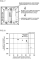
- Grain-oriented electrical steel sheets (subjected to linear strain-introducing magnetic domain refining treatment) having a thickness of 0.23 mm and a magnetic flux density B8 of 1.92 T at a magnetizing force of 800 Aim were used to produce a three-phase stacked transformer core shown in Fig. 4 .
- An electromotive voltage generated between probes was measured at 5 mm intervals in two directions over the entire core surface under three-phase excitation at 50 Hz and 1.7 T to thereby obtain a two-dimensional temporal magnetic flux density waveform.
- the three-phase stacked transformer core shown in Fig. 4 has a shape with a stacked thickness of 15 mm, 5 step laps, and a single layer lap length of 2 mm.
- (dB/dt) is a value obtained by differentiating a local magnetic flux density B(T) with respect to time t (second)
- (dB/dt) rms is the root mean square of (dB/dt)
- (dB/dt) ave is the simple average of (dB/dt).
- Grain-oriented electrical steel sheets having the core shape in Fig. 4 a magnetic flux density B8 of 1.91 T at a magnetizing force of 800 A/m, a thickness of 0.20 mm, 0.23 mm, or 0.27 mm were used to produce transformer cores with different lap joint lengths from 1 to 3 mm.
- the magnetization state in each joint portion of each transformer was examined using a search coil, and the iron loss immediately above each joint lap, the iron loss of each transformer core, and the BF were examined using the probe method described above.
- the form factor, the maximum magnetic flux density in the direction orthogonal to the rolling direction, the transfer magnetic flux density, and the iron loss directly above the joint portion increase.
- the reason for this may be as follows.
- Fig. 5 schematically shows the flows of the magnetic flux in a joint portion that are estimated based on Non Patent Literature 2.
- the magnetic flux reaching the joint portion can be divided into (A) transfer magnetic flux (that transfers lap portions in an out-of-plane direction), (B) interlaminar magnetic flux (that transfers spaces between stacked steel sheets in portions other than the lap portions), and (C) magnetic flux crossing Gaps (between steel sheets)
- the magnetic flux that has reached the joint portion (A) the transfer magnetic flux + (B) the interlaminar magnetic flux + (C) the magnetic flux crossing the Gaps).
- (C) the magnetic flux crossing the Gaps can be computed.
- the magnetic flux density crossing the Gaps can be computed.
- Fig. 6 shows the relation between the magnetic flux density crossing the Gaps and the BF. It was newly found that the correlation between the magnetic flux density crossing the Gaps and the BF is very high.
- the width of the Gap portions is generally larger than the gaps between steel sheets in the stacking direction ( ⁇ the thickness of surface coatings on the electrical steel sheets (about several micrometers)), but this depends on the accuracy of assembly.
- the magnetic resistance for (C) the magnetic flux crossing the Gaps may be larger than the magnetic resistance for (A) the transfer magnetic flux and the magnetic resistance for (B) the interlaminar magnetic flux. Therefore, as the magnetic flux density crossing the Gaps increases, the magnetic resistance of the joint portion may increase.
- the increase in the magnetic resistance of the joint portion directly causes the iron loss of the joint portion to increase largely, and, at the same time, the magnetic flux waveform distortion (waveform ratio) in the core and the rotated magnetic flux (the maximum magnetic flux density in the direction orthogonal to the rolling direction) are increased according to the logic described below.
- the magnetic flux waveform distortion (form factor) and the rotated magnetic flux increase, the iron loss increases accordingly, and this may result in an increase in the transformer iron loss and an increase in the BF.
- Fig. 7 shows a schematic illustration of magnetic flux flows in a three-phase three-leg core at a certain moment (at the moment when a U-leg and a V-leg are excited and a W-leg is not excited).
- the magnetic flux flows into the non-excited W-leg.
- This phenomenon is significant when a material with high permeability anisotropy such as grain-oriented electrical steel sheets is used for the core.
- the lengthwise direction of the grain-oriented electrical steel sheets is their easy magnetization direction RD (rolling direction). Since the magnetic flux easily flows in the RD, the magnetic flux flows also into the W-leg.
- the magnetic resistance of joint portions is related to the magnetic flux flowing into the leg other than the excited legs.
- the magnetic resistance of each of the joint portions is large, the magnetic flux flow between the U and V legs, which is a main magnetic flux flow, is impeded, so that the magnetic flux flowing into the W-leg increases.
- Rotated magnetic flux in yoke central portions in a direction orthogonal to the rolling direction is caused by diversion of the magnetic flux flowing into the leg other than the excited legs. Therefore, as the amount of the magnetic flux flowing into the leg other than the excited legs increases, the maximum magnetic flux density in the yoke central portions in the direction orthogonal to the rolling direction may increase.
- the magnetic flux waveform is distorted in leg end portions according to the amount of the flow, and the form factor becomes large in the leg end portions.
- the magnetic flux waveform distortion (form factor) and the rotated magnetic flux increase.
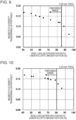
- W A in formula (1) is the iron loss under 50 Hz elliptic magnetization of 1.7 T in an RD direction (rolling direction) and 1.0 T in a TD direction (a direction orthogonal to the rolling direction), and W B is the iron loss under 50 Hz alternating magnetization of 1.7 T in the RD direction.
- Fig. 8 shows the results for a 0.18 mm-thick material
- Fig. 9 shows the results for a 0.20 mm-thick material
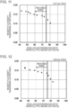
- Fig. 10 shows the results for a 0.23 mm-thick material
- Fig. 11 shows the results for a 0.27 mm-thick material
- Fig. 12 shows the results for a 0.30 mm-thick material.
- the reason for the correlation between the iron loss deterioration ratio under the elliptic magnetization and the magnetic flux density transferring the lap portions is not clear, the present inventors think that the reason is as follows.
- magnetic flux transfers steel sheets in an out-of-plane direction
- magnetic poles are formed at the interfaces between the steel sheets, and this causes a very large increase in magnetostatic energy.
- the magnetization state is changed such that a demagnetizing field is generated in an out-of-plane direction in order to reduce the magnetostatic energy.
- an increase in the number of lancet domain structures in the steel sheets, generation of a demagnetizing field at crystal grain boundaries, etc. occur.
- the magnetization direction is momentarily oriented in a ⁇ 111> direction, which is a hard magnetization direction.
- the iron loss under elliptic magnetization increases more significantly than the iron loss under alternating magnetization only in the easy magnetization direction. Specifically, it is inferred that the iron loss deterioration ratio under elliptic magnetization is correlated with a change in the magnetic flux density transferring the lap portions because of the same change factor, i.e., the generation of the demagnetizing field.
- the magnitude of the magnetic flux density transferring the lap portions or the magnitude of the iron loss under elliptic magnetization can be estimated by parameterizing factors such as an increase in the number of lancet domain structures in the steel sheets, the generation of a demagnetizing field at the crystal grain boundaries, and, in a magnetic domain refined material, an increase in the number of closure domains induced in the strain-introduced portions.
- the closure domain area ratio per unit area of the steel sheets is (w/a) ⁇ 10 -3 . Accordingly, the demagnetizing field generated by the closure domains may increase in proportion to w/a/ ⁇ 2.
- the material factors and the measurement results are summarized in Table 2, and the relation between the inventive parameter [Sin ⁇ + 4t/R + (w/a/ ⁇ 2) ⁇ 10 -3 ] and the iron loss deterioration ratio is summarized in Fig. 13 .
- the inventive parameter is 0.080 or more.
- the secondary recrystallized grains tend to be coarse, and the diameter R of the secondary recrystallized grains can be as large as 40 mm or more.
- the demagnetizing field generated at the crystal grain boundaries is small, and the iron loss deterioration ratio under elliptic magnetization is large as described above, so that the BF increases.
- the BF can be reduced even when the B8 is 1.94 T or more and the diameter R of the secondary recrystallized grains is 40 mm or more. Therefore, by controlling the B8 to 1.94 T or more, the diameter R of the secondary recrystallized grains to 40 mm or more, and the inventive parameter within the range of 0.080 or more, grain-oriented electrical steel sheets in which the magnetic property (iron loss) of the raw material is very small, which allow the BF to be small, and which can form a transformer with very small iron loss can be provided.
- the present invention has been completed based on the above findings. Specifically, the present invention has the following structures.
- a grain-oriented electrical steel sheet that, when used for a stacked core of a transformer, is excellent in the effect of reducing transformer iron loss.
- the magnetic resistance of lap joint portions can be reduced, and the transformer iron loss of the stacked core transformer can be reduced irrespective of the design of the transformer core.
- the stacked core transformer obtained has a small building factor.
- W A is iron loss under 50 Hz elliptic magnetization of 1.7 T in an RD direction (a rolling direction) and 1.0 T in a TD direction (a direction orthogonal to the rolling direction)
- W B is iron loss under 50 Hz alternating magnetization of 1.7 T in the RD direction.
- the iron loss in formula (1) above is measured as follows.
- W A is measured using a two-dimensional single-sheet tester (2D-SST) described in, for example, Non Patent Literature 3.
- 2D-SST two-dimensional single-sheet tester
- a grain-oriented electrical steel sheet (raw material) is subjected to 50 Hz sine wave excitation at a maximum magnetic flux density of 1.7 T in the RD direction and a maximum magnetic flux density of 1.0 T in the TD direction, and the difference in phase between the RD direction and the TD direction during the sine wave excitation is set to 90° to perform excitation under elliptic magnetization.
- the measurement value of the iron loss depends on the rotation direction of the elliptic magnetization and that the measurement value using a clockwise rotation direction differs from the measurement value using a counterclockwise rotation direction.
- the excitation voltage is feedback-controlled such that the maximum magnetic flux density in the RD direction is 1.7 T and the maximum magnetic flux density in the TD direction is 1.0 T.
- waveform control is not performed except for the moment when the magnetic flux density is maximum even though the waveform of the magnetic flux is slightly distorted from the sine wave.
- the measurement sample has a size of (50 mm ⁇ 50 mm) or larger in consideration of the number of crystal grains contained in one sample, but this depends on the excitable size of the two-dimensional single-sheet tester. In consideration of variations in the measurement values, it is preferable that at least 30 samples are used for the measurement for one raw material and the average of the measurement values is used.
- W B is measured using the same samples and the same measurement device as those used for the measurement under the elliptic magnetization.
- 50 Hz sine wave excitation is performed at a maximum magnetic flux density of 1.7 T only in the RD direction.
- the excitation voltage is feedback-controlled such that the maximum magnetic flux density in the RD direction is 1.7 T, and no control is performed in the TD direction.
- a plurality of linear strains extending in a direction intersecting the rolling direction are formed on the surface of the grain-oriented electrical steel sheet (raw material) such that the width w of closure domains formed by the strains, the diameter R of secondary recrystallized grains in the steel sheet, and the average ⁇ angle of the secondary recrystallized grains in the steel sheet satisfy the relation represented by formula (2) below.
- formula (2) [Math. 4] Sin ⁇ + 4 t/R + w/a/ ⁇ 2 ⁇ 10 ⁇ 3 ⁇ 0.080 , In formula (2),
- the ⁇ angle is defined as the angle between the ⁇ 100> axis of secondary recrystallized grains oriented in the rolling direction of the steel sheet and the rolling surface.
- the secondary recrystallization orientation of the steel sheet is measured by X-ray crystal diffraction. Since the orientations of the secondary recrystallized grains in the steel sheet vary, the measurement is performed at points arranged at a 10 mm RD pitch and a 10 mm TD pitch, and the data measured over a measurement area of (500 mm ⁇ 500 mm) or larger is averaged to determine the average ⁇ angle.
- a coating on the surface of the steel sheet is removed by any chemical or electrical method, and the diameters of the secondary recrystallized grains are measured.
- the number of crystal grains with a size of about 1 mm 2 or larger present in a measurement area with a size of (500 mm ⁇ 500 mm) or larger is measured by visual inspection or digital image processing, and the average area for one secondary recrystallized grain is determined. The average area is used to compute a circle-equivalent diameter to determine the diameter of the secondary recrystallized grains.
- the measurement is performed by magnetic domain observation using the Bitter method.
- the width of the closure domains means portions in which their magnetic domain structure is locally disrupted by the strains introduced and in which the magnetic domain structure parallel to the rolling direction is disconnected or discontinuous. Since the width is not always constant, observation is performed at at least five points along one linear row within a length of 100 mm in a sample, and their average is used as the closure domain width in the linear row. Moreover, at least five linear rows within a longitudinal length of 500 mm in the sample are observed, and their average is used as the width w.
- the intervals are defined as the intervals between linear strained portions in the RD direction.
- the intervals between the lines are not constant, the examination is performed at five points within a longitudinal length of 500 mm, and their average is used.
- the line intervals between linear strained regions vary in the width direction of the steel sheet, their average is used.
- a method for producing a grain-oriented electrical steel sheet satisfying the above relations will be described. No particular limitation is imposed on the production method. Any method other than the following method can be used so long as formula (2) can be satisfied by controlling the parameters.
- the average ⁇ angle of the secondary recrystallized grains can be controlled by controlling the primary recrystallization texture or using, for example, a coil set for finishing annealing.
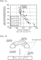
- a coil set for finishing annealing For example, when finishing annealing is performed with the coil set formed as shown in Fig. 14 , the ⁇ 001> directions of the crystal grains in the annealed state are uniformly aligned. Then flattening annealing is performed, and the coil is flattened. In this state, the ⁇ 001> direction of each crystal grain is inclined in the sheet thickness direction according to the coil set used for the finishing annealing, and the ⁇ angle increases. Specifically, the smaller the coil set, the larger the ⁇ angle after the flattening annealing. If the ⁇ angle is excessively large, the magnetic flux density B8 of the raw material decreases, and hysteresis loss deteriorates. Therefore, the ⁇ angle is preferably 5° or less.
- the diameter (mm) of the secondary recrystallized grains can be controlled by controlling the amount of Goss grains present in the primary recrystallized grains. For example, by increasing the final reduction ratio in cold rolling or increasing friction during rolling to thereby increase the amount of shear strain introduced before primary recrystallization of grains, the amount of the Goss grains in the primary recrystallized grains can be increased. Moreover, the amount of the Goss grains present in the primary recrystallized grains can be controlled also by controlling the heating-up rate during primary recrystallization annealing. The Goss grains in the primary recrystallized grains serve as secondary recrystallization nuclei during finishing annealing. Therefore, the larger the amount of the Goss grains, the larger the amount of secondary recrystallized grains, and therefore the smaller the diameter of the secondary recrystallized grains.
- any of various modes such as fiber, CO 2 , and YAG lasers can be used.
- a continuous irradiation-type laser or pulse oscillation-type laser irradiation such as Q switch-type laser irradiation may be used so long as formula (1) of claim 1 is satisfied.
- No particular limitation is imposed on the average laser power P (W), the beam scanning speed V (m/s), and the beam diameter d (mm) during laser irradiation so long as formula (1) of claim 1 is satisfied.
- the energy input amount per unit length P/V is preferably larger than 10 W-s/m.
- the conditions for forming the linear strains by electron beam irradiation will be described. No particular limitation is imposed on the acceleration voltage E (kv) the beam current I (mA), and the beam scanning speed V (m/s) during the irradiation so long as formula (1) of claim 1 is satisfied. However, since it is necessary to obtain a sufficient magnetic domain refining effect, the energy input amount per unit length E ⁇ I/V is preferably larger than 6 W-s/m. Preferably, the degree of vacuum in a processing chamber in which the steel sheet is irradiated with the electron beam is 2 Pa or lower.
- the beams is dispersed by residual gas in a path from the electron gun to the steel sheet, and the magnetic domain refining effect becomes small.
- the steel sheet may be irradiated continuously or in a dotted manner.
- a method for introducing strains in a dotted manner while the beam is scanned rapidly, the scanning of the beam is suspended at prescribed time intervals. The irradiation with the beam is continued at the stopped position for a time suitable for the present invention, and then the scanning is resumed. This process is repeated to obtain strains arranged in the dotted manner.
- a high-capacity amplifier may be used to change the deflection voltage for the electron beam. If the intervals between the dots during irradiation in the dotted manner are excessively large, the magnetic domain refining effect becomes small. Therefore, the intervals are preferably 0.40 mm or less.
- the width of the closure domains it is important to control the beam diameter in the laser irradiation or the electron beam irradiation.
- the beam diameter can be increased by changing the optical conditions (such as the focal length) of a lens.
- the beam diameter can be increased by changing the current conditions for a converging magnetic coil to control the focal length.
- the width of the closure domains is large. However, if the width of the closure domains is excessively large, the amount of stains introduced is excessively large. In this case, the magnetic flux density B8 of the raw material becomes small, and the hysteresis loss deteriorates.
- the upper limit of the width of the closure domains is preferably 400 ⁇ m or less.
- the lower limit is not specified. However, from the viewpoint of obtaining the magnetic domain refining effect sufficiently, the lower limit is preferably 20 ⁇ m or more.
- the intervals between the plurality of liner strains extending in the direction intersecting the rolling direction can be controlled by controlling the beam irradiation intervals. If the intervals between the strains are excessively large, the magnetic domain refining effect obtained by the strains is reduced. Therefore, the intervals are preferably 18 mm or less.
- the sheet thickness of the grain-oriented electrical steel sheet of the present invention is preferably 0.15 mm or more and more preferably 0.18 mm or more. From the viewpoint of reducing eddy-current loss etc., the sheet thickness is preferably 0.35 mm or less and more preferably 0.30 mm or less.
- An inhibitor may be used.
- an AlN-based inhibitor when, for example, an AlN-based inhibitor is used, appropriate amounts of Al and N may be added.
- MnS-MnSe-based inhibitor when used, appropriate amounts of Mn and Se and/or S may be added. Of course, both the inhibitors may be used in combination.
- preferred contents of Al, N, S, and Se are Al: 0.01 to 0.065% by mass, N: 0.005 to 0.012% by mass, S: 0.005 to 0.03% by mass, and Se: 0.005 to 0.03% by mass.
- the present invention can be applied also to a grain-oriented electrical steel sheet in which the contents of Al, N, S, and Se are limited, i.e., no inhibitor is used.
- the amounts of Al, N, S, and Se are limited to Al: 100 mass ppm or less, N: 50 mass ppm or less, S: 50 mass ppm or less, and Se: 50 mass ppm or less.
- the content of C exceeds 0.08% by mass, it is difficult to reduce the C content to 50 mass ppm or less at which magnetic aging does not occur during the production process. Therefore, the C content is preferably 0.08% by mass or less. The lower limit is not provided because secondary recrystallization can occur even in a raw material containing no C.
- Si is an element effective in increasing the electric resistance of steel and reducing iron loss.
- the content of Si is less than 2.0% by mass, the effect of reducing the iron loss is insufficient. If the content of Si exceeds 8.0% by mass, workability deteriorates significantly, and the magnetic flux density deceases. Therefore, the Si content is preferably within the range of 2.0 to 8.0% by mass.
- Mn is an element necessary for improving hot workability. However, if the Mn content is less than 0.005% by mass, the effect of Mn added is small. If the Mn content exceeds 1.0% by mass, the magnetic flux density of a product sheet decreases. Therefore, the Mn content is preferably within the range of 0.005 to 1.0% by mass.
- the following elements may be appropriately added as components improving the magnetic properties.
- Ni is an element useful to improve the texture of a hot-rolled sheet to thereby improve its magnetic properties. However, if the content is less than 0.03% by mass, the effect of improving the magnetic properties is small. If the content exceeds 1.50% by mass, secondary recrystallization is unstable, so that the magnetic properties deteriorate. Therefore, the amount of Ni is within the range of preferably 0.03 to 1.50% by mass.
- Sn, Sb, Cu, P, Mo, and Cr are elements useful to improve the magnetic properties. However, if their contents are lower than their lower limits, the effect of improving the magnetic properties is small. If the contents exceed the upper limits of the components, the growth of the secondary recrystallized grains is impeded. It is therefore preferable that the contents of these components are within the respective ranges described above. The remainder other than the above components is Fe and inevitable impurities mixed during the production process.
- the steel having a component composition adjusted to the above preferred component composition may be subjected to a standard ingot making process or a standard continuous casting process to form a slab, or a thin cast piece having a thickness of 100 mm or less may be produced by direct continuous casting process.
- the slab is heated using a common method and then hot-rolled. However, the slab may be subjected directly to hot-rolling without heating after casting.
- the steel may be hot-rolled or may be subjected to the subsequent process with the hot-rolling omitted. Then the hot-rolled sheet is optionally annealed and then subjected to cold rolling one time or subjected to cold rolling twice or more with intermediate annealing interposed therebetween to obtain a final sheet thickness.
- the product is subjected to decarbonization annealing and finishing annealing. Then an insulating tension coating is applied, and flattening annealing is performed. Then a plurality of linear strains is formed using a laser or an electron beam. Then an insulating coating may be optionally applied in order to increase insulation and corrosion resistance.
- the C content is reduced to 50 ppm or less by the decarbonization annealing, and the contents of Al, N, S, and Se are reduced to the level of inevitable impurities by purification in the finishing annealing.
- the present invention is suitable for selecting a grain-oriented electrical steel sheet as a raw material for stacked core transformers having other joint portion structures such as three-phase five-leg cores and single-phase excitation-type cores.
- the stacked core A shown in Fig. 15 is an alternately stacked core having a stacked thickness of 15 mm and a lap length of 6 mm.
- the stacked core B is a five-step lap core having a stacked thickness of 15 mm and a single layer lap length of 1.5 mm
- the stacked core C is a five-step lap core having a stacked thickness of 15 mm and a single layer lap length of 2 mm.
- the BF for each of the core shapes was smaller than those in Comparative Examples.
Landscapes
- Engineering & Computer Science (AREA)
- Chemical & Material Sciences (AREA)
- Power Engineering (AREA)
- Metallurgy (AREA)
- Materials Engineering (AREA)
- Mechanical Engineering (AREA)
- Organic Chemistry (AREA)
- Dispersion Chemistry (AREA)
- Manufacturing & Machinery (AREA)
- Physics & Mathematics (AREA)
- Electromagnetism (AREA)
- Thermal Sciences (AREA)
- Crystallography & Structural Chemistry (AREA)
- Soft Magnetic Materials (AREA)
- Manufacturing Of Steel Electrode Plates (AREA)
- Manufacturing Cores, Coils, And Magnets (AREA)
Claims (2)
- Verfahren zur Auswahl eines kornorientierten Elektrostahlblechs zur Verwendung als Rohstoff für einen gestapelten Kern eines gestapelten Kerntransformators,eine Vielzahl von linearen Dehnungen, die sich in eine Richtung erstrecken, die eine Walzrichtung schneidet, die auf einer Oberfläche des Stahlblechs gebildet wird,Verfahren, bei dem als Rohstoff das kornorientierte Elektrostahlblech ausgewählt wird, wenn die Breite w der durch die Dehnungen gebildeten Verschlussdomänen, der Durchmesser R der sekundär rekristallisierten Körner im Stahlblech und ein mittlerer β-Winkel der sekundär rekristallisierten Körner im Stahlblech der Beziehung der folgenden Formel (1) genügen:
 wobei in Formel (1)β: der mittlere β-Winkel (°) der sekundär rekristallisierten Körner,t: die Dicke (mm) des Stahlblechs,R: der Durchmesser (mm) der sekundär rekristallisierten Körner,w: die Breite (pm) der Verschlussdomänen unda: die Abstände (mm) zwischen der Vielzahl linearer Dehnungen, die sich in die Richtung erstrecken, die die Walzrichtung schneidet.
 - Verfahren zur Herstellung eines gestapelten Kerns eines gestapelten Kerntransformators, wobei durch das Verfahren ein Baufaktor reduziert werden kann, und zwar der Baufaktor, der durch Dividieren des Wertes des Eisenverlusts des gestapelten Kerntransformators durch den Wert des Eisenverlusts von kornorientierten Elektrostahlblechen, die als Rohstoff des gestapelten Kerns verwendet werden, erhalten wird,
wobei das Verfahren Folgendes umfasst:Auswählen der kornorientierten Elektrostahlbleche zur Verwendung als Rohstoff des gestapelten Kerns gemäß dem Verfahren nach Anspruch 1; undBilden des gestapelten Kerns aus den ausgewählten kornorientierten Elektrostahlblechen.
Applications Claiming Priority (2)
| Application Number | Priority Date | Filing Date | Title |
|---|---|---|---|
| JP2018014245 | 2018-01-31 | ||
| PCT/JP2019/003402 WO2019151401A1 (ja) | 2018-01-31 | 2019-01-31 | 方向性電磁鋼板およびこれを用いてなる変圧器の積鉄心並びに積鉄心の製造方法 |
Publications (3)
| Publication Number | Publication Date |
|---|---|
| EP3734623A1 EP3734623A1 (de) | 2020-11-04 |
| EP3734623A4 EP3734623A4 (de) | 2021-03-10 |
| EP3734623B1 true EP3734623B1 (de) | 2024-09-18 |
Family
ID=67479274
Family Applications (1)
| Application Number | Title | Priority Date | Filing Date |
|---|---|---|---|
| EP19748059.3A Active EP3734623B1 (de) | 2018-01-31 | 2019-01-31 | Verfahren zur auswahl kornorientierter elektrostahlbleche |
Country Status (9)
| Country | Link |
|---|---|
| US (1) | US11495378B2 (de) |
| EP (1) | EP3734623B1 (de) |
| JP (1) | JP7028244B2 (de) |
| KR (1) | KR102372003B1 (de) |
| CN (1) | CN111670480B (de) |
| CA (1) | CA3088125C (de) |
| MX (1) | MX2020007951A (de) |
| RU (1) | RU2741585C1 (de) |
| WO (1) | WO2019151401A1 (de) |
Families Citing this family (5)
| Publication number | Priority date | Publication date | Assignee | Title |
|---|---|---|---|---|
| US11984249B2 (en) * | 2018-01-31 | 2024-05-14 | Jfe Steel Corporation | Grain-oriented electrical steel sheet, wound transformer core using the same, and method for producing wound core |
| IT202000003880A1 (it) * | 2020-02-25 | 2021-08-25 | L A E Lughese Attrezzature Per Lelettromeccanica S R L | Metodo per la composizione di nuclei lamellari, sistema di presa per pacchi lamellari ed impianto di produzione nuclei lamellari |
| CN111368375B (zh) * | 2020-03-04 | 2023-06-20 | 海南金盘智能科技股份有限公司 | 一种变压器心柱叠层方案的确定方法及装置 |
| KR102800849B1 (ko) * | 2020-11-05 | 2025-04-29 | 삼성디스플레이 주식회사 | 표시 장치용 패널 정렬 장치 및 패널 정렬 방법 |
| US20250347753A1 (en) * | 2022-05-30 | 2025-11-13 | Jfe Steel Corporation | Data set generation method, electromagnetic field analysis method and a non-transitory computer readable medium |
Family Cites Families (26)
| Publication number | Priority date | Publication date | Assignee | Title |
|---|---|---|---|---|
| JPS5241660A (en) | 1975-09-30 | 1977-03-31 | Kureha Chem Ind Co Ltd | Resin composition of low permeabilities to moisture and gases |
| JPS5484229A (en) | 1977-12-19 | 1979-07-05 | Nippon Steel Corp | Reducing method of iron loss of three phase transformer iron core |
| JPS5518566A (en) | 1978-07-26 | 1980-02-08 | Nippon Steel Corp | Improving method for iron loss characteristic of directional electrical steel sheet |
| JPS60198226A (ja) | 1984-03-23 | 1985-10-07 | Mitsui Toatsu Chem Inc | 多層フイルムの製造方法 |
| JPH0672266B2 (ja) | 1987-01-28 | 1994-09-14 | 川崎製鉄株式会社 | 超低鉄損一方向性珪素鋼板の製造方法 |
| JPH01283912A (ja) | 1988-05-11 | 1989-11-15 | Hitachi Ltd | 電気機器鉄心の組立方法 |
| US5507883A (en) * | 1992-06-26 | 1996-04-16 | Nippon Steel Corporation | Grain oriented electrical steel sheet having high magnetic flux density and ultra low iron loss and process for production the same |
| JP3082460B2 (ja) | 1992-08-31 | 2000-08-28 | タカタ株式会社 | エアバッグ装置 |
| JP2757724B2 (ja) | 1992-12-11 | 1998-05-25 | 三菱電機株式会社 | 三相三脚変圧器鉄心 |
| US5296051A (en) | 1993-02-11 | 1994-03-22 | Kawasaki Steel Corporation | Method of producing low iron loss grain-oriented silicon steel sheet having low-noise and superior shape characteristics |
| DE69810852T2 (de) | 1997-07-17 | 2003-06-05 | Kawasaki Steel Corp., Kobe | Kornorientiertes Elektrostahlblech mit ausgezeichneten magnetischen Eigenschaften und dessen Herstellungsverfahren |
| JP2005240079A (ja) | 2004-02-25 | 2005-09-08 | Jfe Steel Kk | 鉄損劣化率が小さい方向性電磁鋼板 |
| JP5750820B2 (ja) | 2009-09-29 | 2015-07-22 | Jfeスチール株式会社 | 鉄損測定方法 |
| JP2011084778A (ja) * | 2009-10-15 | 2011-04-28 | Nippon Steel Corp | 高周波励磁用無方向性電磁鋼板 |
| JP5754097B2 (ja) * | 2010-08-06 | 2015-07-22 | Jfeスチール株式会社 | 方向性電磁鋼板およびその製造方法 |
| JP2012057232A (ja) * | 2010-09-10 | 2012-03-22 | Jfe Steel Corp | 方向性電磁鋼板およびその製造方法 |
| MX2013002627A (es) * | 2010-09-10 | 2013-04-24 | Jfe Steel Corp | Lamina de acero magnetica de grano orientado y proceso para producir la misma. |
| JP5793859B2 (ja) * | 2010-12-16 | 2015-10-14 | Jfeスチール株式会社 | 方向性電磁鋼板およびその製造方法 |
| JP5594437B2 (ja) | 2011-09-28 | 2014-09-24 | Jfeスチール株式会社 | 方向性電磁鋼板およびその製造方法 |
| JP6090553B2 (ja) * | 2011-11-24 | 2017-03-08 | Jfeスチール株式会社 | 三相変圧器用鉄心 |
| JP6007501B2 (ja) * | 2012-02-08 | 2016-10-12 | Jfeスチール株式会社 | 方向性電磁鋼板 |
| US10629346B2 (en) | 2012-04-26 | 2020-04-21 | Jfe Steel Corporation | Method of manufacturing grain-oriented electrical steel sheet |
| JP5668795B2 (ja) * | 2013-06-19 | 2015-02-12 | Jfeスチール株式会社 | 方向性電磁鋼板およびそれを用いた変圧器鉄心 |
| US20170298467A1 (en) * | 2014-10-06 | 2017-10-19 | Jfe Steel Corporation | Low iron loss grain oriented electrical steel sheet and method for manufacturing the same |
| JP6465048B2 (ja) * | 2016-02-19 | 2019-02-06 | Jfeスチール株式会社 | 方向性電磁鋼板の製造方法 |
| US11984249B2 (en) * | 2018-01-31 | 2024-05-14 | Jfe Steel Corporation | Grain-oriented electrical steel sheet, wound transformer core using the same, and method for producing wound core |
-
2019
- 2019-01-31 CA CA3088125A patent/CA3088125C/en active Active
- 2019-01-31 MX MX2020007951A patent/MX2020007951A/es unknown
- 2019-01-31 WO PCT/JP2019/003402 patent/WO2019151401A1/ja not_active Ceased
- 2019-01-31 EP EP19748059.3A patent/EP3734623B1/de active Active
- 2019-01-31 RU RU2020125347A patent/RU2741585C1/ru active
- 2019-01-31 US US16/966,268 patent/US11495378B2/en active Active
- 2019-01-31 JP JP2019524292A patent/JP7028244B2/ja active Active
- 2019-01-31 CN CN201980011020.XA patent/CN111670480B/zh active Active
- 2019-01-31 KR KR1020207022135A patent/KR102372003B1/ko active Active
Also Published As
| Publication number | Publication date |
|---|---|
| EP3734623A4 (de) | 2021-03-10 |
| CA3088125C (en) | 2022-09-20 |
| MX2020007951A (es) | 2020-09-24 |
| RU2741585C1 (ru) | 2021-01-27 |
| US20200373046A1 (en) | 2020-11-26 |
| WO2019151401A1 (ja) | 2019-08-08 |
| JPWO2019151401A1 (ja) | 2020-12-03 |
| JP7028244B2 (ja) | 2022-03-02 |
| CN111670480B (zh) | 2022-09-20 |
| KR102372003B1 (ko) | 2022-03-08 |
| KR20200103091A (ko) | 2020-09-01 |
| CN111670480A (zh) | 2020-09-15 |
| CA3088125A1 (en) | 2019-08-08 |
| US11495378B2 (en) | 2022-11-08 |
| EP3734623A1 (de) | 2020-11-04 |
Similar Documents
| Publication | Publication Date | Title |
|---|---|---|
| US11984249B2 (en) | Grain-oriented electrical steel sheet, wound transformer core using the same, and method for producing wound core | |
| EP3734623B1 (de) | Verfahren zur auswahl kornorientierter elektrostahlbleche | |
| EP2602347B1 (de) | Kornorientiertes magnetisches stahlblech und herstellungsverfahren dafür | |
| CN104011246B (zh) | 取向性电磁钢板 | |
| KR101607909B1 (ko) | 방향성 전자 강판 및 그것을 이용한 변압기 철심 | |
| JP2007314826A (ja) | 鉄損特性に優れた一方向性電磁鋼板 | |
| JP2000345306A (ja) | 高磁場鉄損の優れた高磁束密度一方向性電磁鋼板 | |
| JP4192399B2 (ja) | 方向性電磁鋼板およびその製造方法 | |
| JP3333798B2 (ja) | 鉄損の低い方向性電磁鋼板 | |
| JP6973369B2 (ja) | 方向性電磁鋼板およびその製造方法 | |
| WO2024063163A1 (ja) | 方向性電磁鋼板 | |
| JP7318846B1 (ja) | 三相三脚巻鉄心およびその製造方法 | |
| JP7318845B1 (ja) | 三相三脚巻鉄心およびその製造方法 | |
| EP4343796A1 (de) | Gewickelter kern und verfahren zur herstellung eines gewickelten kerns | |
| JP7648871B2 (ja) | 巻鉄心 | |
| EP4675653A1 (de) | Eisenkern für transformator und transformator | |
| WO2023167016A1 (ja) | 三相三脚巻鉄心およびその製造方法 | |
| WO2023167015A1 (ja) | 三相三脚巻鉄心およびその製造方法 |
Legal Events
| Date | Code | Title | Description |
|---|---|---|---|
| STAA | Information on the status of an ep patent application or granted ep patent |
Free format text: STATUS: THE INTERNATIONAL PUBLICATION HAS BEEN MADE |
|
| PUAI | Public reference made under article 153(3) epc to a published international application that has entered the european phase |
Free format text: ORIGINAL CODE: 0009012 |
|
| STAA | Information on the status of an ep patent application or granted ep patent |
Free format text: STATUS: REQUEST FOR EXAMINATION WAS MADE |
|
| 17P | Request for examination filed |
Effective date: 20200726 |
|
| AK | Designated contracting states |
Kind code of ref document: A1 Designated state(s): AL AT BE BG CH CY CZ DE DK EE ES FI FR GB GR HR HU IE IS IT LI LT LU LV MC MK MT NL NO PL PT RO RS SE SI SK SM TR |
|
| AX | Request for extension of the european patent |
Extension state: BA ME |
|
| A4 | Supplementary search report drawn up and despatched |
Effective date: 20210204 |
|
| RIC1 | Information provided on ipc code assigned before grant |
Ipc: C21D 8/12 20060101ALI20210129BHEP Ipc: C22C 38/02 20060101ALI20210129BHEP Ipc: H01F 41/02 20060101ALI20210129BHEP Ipc: C22C 38/04 20060101ALI20210129BHEP Ipc: H01F 1/147 20060101ALI20210129BHEP Ipc: H01F 1/16 20060101AFI20210129BHEP Ipc: H01F 27/245 20060101ALI20210129BHEP |
|
| DAV | Request for validation of the european patent (deleted) | ||
| DAX | Request for extension of the european patent (deleted) | ||
| STAA | Information on the status of an ep patent application or granted ep patent |
Free format text: STATUS: EXAMINATION IS IN PROGRESS |
|
| 17Q | First examination report despatched |
Effective date: 20221128 |
|
| REG | Reference to a national code |
Ref country code: DE Ref legal event code: R079 Free format text: PREVIOUS MAIN CLASS: H01F0001147000 Ipc: H01F0001160000 Ref document number: 602019059096 Country of ref document: DE |
|
| GRAP | Despatch of communication of intention to grant a patent |
Free format text: ORIGINAL CODE: EPIDOSNIGR1 |
|
| STAA | Information on the status of an ep patent application or granted ep patent |
Free format text: STATUS: GRANT OF PATENT IS INTENDED |
|
| RIC1 | Information provided on ipc code assigned before grant |
Ipc: C22C 38/60 20060101ALI20240102BHEP Ipc: C22C 38/44 20060101ALI20240102BHEP Ipc: C22C 38/42 20060101ALI20240102BHEP Ipc: C22C 38/02 20060101ALI20240102BHEP Ipc: C21D 8/12 20060101ALI20240102BHEP Ipc: H01F 41/02 20060101ALI20240102BHEP Ipc: H01F 27/245 20060101ALI20240102BHEP Ipc: H01F 1/147 20060101ALI20240102BHEP Ipc: H01F 1/16 20060101AFI20240102BHEP |
|
| INTG | Intention to grant announced |
Effective date: 20240202 |
|
| GRAJ | Information related to disapproval of communication of intention to grant by the applicant or resumption of examination proceedings by the epo deleted |
Free format text: ORIGINAL CODE: EPIDOSDIGR1 |
|
| STAA | Information on the status of an ep patent application or granted ep patent |
Free format text: STATUS: EXAMINATION IS IN PROGRESS |
|
| INTC | Intention to grant announced (deleted) | ||
| GRAP | Despatch of communication of intention to grant a patent |
Free format text: ORIGINAL CODE: EPIDOSNIGR1 |
|
| STAA | Information on the status of an ep patent application or granted ep patent |
Free format text: STATUS: GRANT OF PATENT IS INTENDED |
|
| INTG | Intention to grant announced |
Effective date: 20240611 |
|
| GRAS | Grant fee paid |
Free format text: ORIGINAL CODE: EPIDOSNIGR3 |
|
| GRAA | (expected) grant |
Free format text: ORIGINAL CODE: 0009210 |
|
| STAA | Information on the status of an ep patent application or granted ep patent |
Free format text: STATUS: THE PATENT HAS BEEN GRANTED |
|
| AK | Designated contracting states |
Kind code of ref document: B1 Designated state(s): AL AT BE BG CH CY CZ DE DK EE ES FI FR GB GR HR HU IE IS IT LI LT LU LV MC MK MT NL NO PL PT RO RS SE SI SK SM TR |
|
| REG | Reference to a national code |
Ref country code: GB Ref legal event code: FG4D |
|
| REG | Reference to a national code |
Ref country code: CH Ref legal event code: EP |
|
| REG | Reference to a national code |
Ref country code: IE Ref legal event code: FG4D |
|
| REG | Reference to a national code |
Ref country code: DE Ref legal event code: R096 Ref document number: 602019059096 Country of ref document: DE |
|
| REG | Reference to a national code |
Ref country code: LT Ref legal event code: MG9D |
|
| PG25 | Lapsed in a contracting state [announced via postgrant information from national office to epo] |
Ref country code: NO Free format text: LAPSE BECAUSE OF FAILURE TO SUBMIT A TRANSLATION OF THE DESCRIPTION OR TO PAY THE FEE WITHIN THE PRESCRIBED TIME-LIMIT Effective date: 20241218 |
|
| PG25 | Lapsed in a contracting state [announced via postgrant information from national office to epo] |
Ref country code: GR Free format text: LAPSE BECAUSE OF FAILURE TO SUBMIT A TRANSLATION OF THE DESCRIPTION OR TO PAY THE FEE WITHIN THE PRESCRIBED TIME-LIMIT Effective date: 20241219 Ref country code: FI Free format text: LAPSE BECAUSE OF FAILURE TO SUBMIT A TRANSLATION OF THE DESCRIPTION OR TO PAY THE FEE WITHIN THE PRESCRIBED TIME-LIMIT Effective date: 20240918 |
|
| PG25 | Lapsed in a contracting state [announced via postgrant information from national office to epo] |
Ref country code: BG Free format text: LAPSE BECAUSE OF FAILURE TO SUBMIT A TRANSLATION OF THE DESCRIPTION OR TO PAY THE FEE WITHIN THE PRESCRIBED TIME-LIMIT Effective date: 20240918 |
|
| PG25 | Lapsed in a contracting state [announced via postgrant information from national office to epo] |
Ref country code: LV Free format text: LAPSE BECAUSE OF FAILURE TO SUBMIT A TRANSLATION OF THE DESCRIPTION OR TO PAY THE FEE WITHIN THE PRESCRIBED TIME-LIMIT Effective date: 20240918 |
|
| PG25 | Lapsed in a contracting state [announced via postgrant information from national office to epo] |
Ref country code: HR Free format text: LAPSE BECAUSE OF FAILURE TO SUBMIT A TRANSLATION OF THE DESCRIPTION OR TO PAY THE FEE WITHIN THE PRESCRIBED TIME-LIMIT Effective date: 20240918 |
|
| REG | Reference to a national code |
Ref country code: NL Ref legal event code: MP Effective date: 20240918 |
|
| PG25 | Lapsed in a contracting state [announced via postgrant information from national office to epo] |
Ref country code: RS Free format text: LAPSE BECAUSE OF FAILURE TO SUBMIT A TRANSLATION OF THE DESCRIPTION OR TO PAY THE FEE WITHIN THE PRESCRIBED TIME-LIMIT Effective date: 20241218 |
|
| PG25 | Lapsed in a contracting state [announced via postgrant information from national office to epo] |
Ref country code: RS Free format text: LAPSE BECAUSE OF FAILURE TO SUBMIT A TRANSLATION OF THE DESCRIPTION OR TO PAY THE FEE WITHIN THE PRESCRIBED TIME-LIMIT Effective date: 20241218 Ref country code: NO Free format text: LAPSE BECAUSE OF FAILURE TO SUBMIT A TRANSLATION OF THE DESCRIPTION OR TO PAY THE FEE WITHIN THE PRESCRIBED TIME-LIMIT Effective date: 20241218 Ref country code: LV Free format text: LAPSE BECAUSE OF FAILURE TO SUBMIT A TRANSLATION OF THE DESCRIPTION OR TO PAY THE FEE WITHIN THE PRESCRIBED TIME-LIMIT Effective date: 20240918 Ref country code: HR Free format text: LAPSE BECAUSE OF FAILURE TO SUBMIT A TRANSLATION OF THE DESCRIPTION OR TO PAY THE FEE WITHIN THE PRESCRIBED TIME-LIMIT Effective date: 20240918 Ref country code: GR Free format text: LAPSE BECAUSE OF FAILURE TO SUBMIT A TRANSLATION OF THE DESCRIPTION OR TO PAY THE FEE WITHIN THE PRESCRIBED TIME-LIMIT Effective date: 20241219 Ref country code: FI Free format text: LAPSE BECAUSE OF FAILURE TO SUBMIT A TRANSLATION OF THE DESCRIPTION OR TO PAY THE FEE WITHIN THE PRESCRIBED TIME-LIMIT Effective date: 20240918 Ref country code: BG Free format text: LAPSE BECAUSE OF FAILURE TO SUBMIT A TRANSLATION OF THE DESCRIPTION OR TO PAY THE FEE WITHIN THE PRESCRIBED TIME-LIMIT Effective date: 20240918 |
|
| REG | Reference to a national code |
Ref country code: AT Ref legal event code: MK05 Ref document number: 1725418 Country of ref document: AT Kind code of ref document: T Effective date: 20240918 |
|
| PG25 | Lapsed in a contracting state [announced via postgrant information from national office to epo] |
Ref country code: NL Free format text: LAPSE BECAUSE OF FAILURE TO SUBMIT A TRANSLATION OF THE DESCRIPTION OR TO PAY THE FEE WITHIN THE PRESCRIBED TIME-LIMIT Effective date: 20240918 |
|
| PG25 | Lapsed in a contracting state [announced via postgrant information from national office to epo] |
Ref country code: IS Free format text: LAPSE BECAUSE OF FAILURE TO SUBMIT A TRANSLATION OF THE DESCRIPTION OR TO PAY THE FEE WITHIN THE PRESCRIBED TIME-LIMIT Effective date: 20250118 Ref country code: PT Free format text: LAPSE BECAUSE OF FAILURE TO SUBMIT A TRANSLATION OF THE DESCRIPTION OR TO PAY THE FEE WITHIN THE PRESCRIBED TIME-LIMIT Effective date: 20250120 |
|
| PG25 | Lapsed in a contracting state [announced via postgrant information from national office to epo] |
Ref country code: RO Free format text: LAPSE BECAUSE OF FAILURE TO SUBMIT A TRANSLATION OF THE DESCRIPTION OR TO PAY THE FEE WITHIN THE PRESCRIBED TIME-LIMIT Effective date: 20240918 Ref country code: SM Free format text: LAPSE BECAUSE OF FAILURE TO SUBMIT A TRANSLATION OF THE DESCRIPTION OR TO PAY THE FEE WITHIN THE PRESCRIBED TIME-LIMIT Effective date: 20240918 |
|
| PG25 | Lapsed in a contracting state [announced via postgrant information from national office to epo] |
Ref country code: ES Free format text: LAPSE BECAUSE OF FAILURE TO SUBMIT A TRANSLATION OF THE DESCRIPTION OR TO PAY THE FEE WITHIN THE PRESCRIBED TIME-LIMIT Effective date: 20240918 |
|
| PG25 | Lapsed in a contracting state [announced via postgrant information from national office to epo] |
Ref country code: EE Free format text: LAPSE BECAUSE OF FAILURE TO SUBMIT A TRANSLATION OF THE DESCRIPTION OR TO PAY THE FEE WITHIN THE PRESCRIBED TIME-LIMIT Effective date: 20240918 Ref country code: AT Free format text: LAPSE BECAUSE OF FAILURE TO SUBMIT A TRANSLATION OF THE DESCRIPTION OR TO PAY THE FEE WITHIN THE PRESCRIBED TIME-LIMIT Effective date: 20240918 |
|
| PG25 | Lapsed in a contracting state [announced via postgrant information from national office to epo] |
Ref country code: CZ Free format text: LAPSE BECAUSE OF FAILURE TO SUBMIT A TRANSLATION OF THE DESCRIPTION OR TO PAY THE FEE WITHIN THE PRESCRIBED TIME-LIMIT Effective date: 20240918 Ref country code: PL Free format text: LAPSE BECAUSE OF FAILURE TO SUBMIT A TRANSLATION OF THE DESCRIPTION OR TO PAY THE FEE WITHIN THE PRESCRIBED TIME-LIMIT Effective date: 20240918 |
|
| PG25 | Lapsed in a contracting state [announced via postgrant information from national office to epo] |
Ref country code: SK Free format text: LAPSE BECAUSE OF FAILURE TO SUBMIT A TRANSLATION OF THE DESCRIPTION OR TO PAY THE FEE WITHIN THE PRESCRIBED TIME-LIMIT Effective date: 20240918 Ref country code: IT Free format text: LAPSE BECAUSE OF FAILURE TO SUBMIT A TRANSLATION OF THE DESCRIPTION OR TO PAY THE FEE WITHIN THE PRESCRIBED TIME-LIMIT Effective date: 20240918 |
|
| REG | Reference to a national code |
Ref country code: DE Ref legal event code: R097 Ref document number: 602019059096 Country of ref document: DE |
|
| PG25 | Lapsed in a contracting state [announced via postgrant information from national office to epo] |
Ref country code: DK Free format text: LAPSE BECAUSE OF FAILURE TO SUBMIT A TRANSLATION OF THE DESCRIPTION OR TO PAY THE FEE WITHIN THE PRESCRIBED TIME-LIMIT Effective date: 20240918 |
|
| PLBE | No opposition filed within time limit |
Free format text: ORIGINAL CODE: 0009261 |
|
| STAA | Information on the status of an ep patent application or granted ep patent |
Free format text: STATUS: NO OPPOSITION FILED WITHIN TIME LIMIT |
|
| 26N | No opposition filed |
Effective date: 20250619 |
|
| REG | Reference to a national code |
Ref country code: CH Ref legal event code: PL |
|
| PG25 | Lapsed in a contracting state [announced via postgrant information from national office to epo] |
Ref country code: SE Free format text: LAPSE BECAUSE OF FAILURE TO SUBMIT A TRANSLATION OF THE DESCRIPTION OR TO PAY THE FEE WITHIN THE PRESCRIBED TIME-LIMIT Effective date: 20240918 |
|
| PG25 | Lapsed in a contracting state [announced via postgrant information from national office to epo] |
Ref country code: MC Free format text: LAPSE BECAUSE OF FAILURE TO SUBMIT A TRANSLATION OF THE DESCRIPTION OR TO PAY THE FEE WITHIN THE PRESCRIBED TIME-LIMIT Effective date: 20240918 Ref country code: LU Free format text: LAPSE BECAUSE OF NON-PAYMENT OF DUE FEES Effective date: 20250131 |
|
| GBPC | Gb: european patent ceased through non-payment of renewal fee |
Effective date: 20250131 |
|
| PG25 | Lapsed in a contracting state [announced via postgrant information from national office to epo] |
Ref country code: GB Free format text: LAPSE BECAUSE OF NON-PAYMENT OF DUE FEES Effective date: 20250131 Ref country code: BE Free format text: LAPSE BECAUSE OF NON-PAYMENT OF DUE FEES Effective date: 20250131 |
|
| PG25 | Lapsed in a contracting state [announced via postgrant information from national office to epo] |
Ref country code: CH Free format text: LAPSE BECAUSE OF NON-PAYMENT OF DUE FEES Effective date: 20250131 |
|
| REG | Reference to a national code |
Ref country code: BE Ref legal event code: MM Effective date: 20250131 |
|
| PGFP | Annual fee paid to national office [announced via postgrant information from national office to epo] |
Ref country code: FR Payment date: 20251128 Year of fee payment: 8 |
|
| PG25 | Lapsed in a contracting state [announced via postgrant information from national office to epo] |
Ref country code: IE Free format text: LAPSE BECAUSE OF NON-PAYMENT OF DUE FEES Effective date: 20250131 |
|
| PGFP | Annual fee paid to national office [announced via postgrant information from national office to epo] |
Ref country code: DE Payment date: 20251210 Year of fee payment: 8 |