EP3734670B1 - Fotovoltaisches energieerzeugungsmodul - Google Patents
Fotovoltaisches energieerzeugungsmodul Download PDFInfo
- Publication number
- EP3734670B1 EP3734670B1 EP18894967.1A EP18894967A EP3734670B1 EP 3734670 B1 EP3734670 B1 EP 3734670B1 EP 18894967 A EP18894967 A EP 18894967A EP 3734670 B1 EP3734670 B1 EP 3734670B1
- Authority
- EP
- European Patent Office
- Prior art keywords
- supportive
- power generation
- photovoltaic power
- generation module
- adhering part
- Prior art date
- Legal status (The legal status is an assumption and is not a legal conclusion. Google has not performed a legal analysis and makes no representation as to the accuracy of the status listed.)
- Active
Links
Images


Classifications
-
- H—ELECTRICITY
- H10—SEMICONDUCTOR DEVICES; ELECTRIC SOLID-STATE DEVICES NOT OTHERWISE PROVIDED FOR
- H10F—INORGANIC SEMICONDUCTOR DEVICES SENSITIVE TO INFRARED RADIATION, LIGHT, ELECTROMAGNETIC RADIATION OF SHORTER WAVELENGTH OR CORPUSCULAR RADIATION
- H10F77/00—Constructional details of devices covered by this subclass
- H10F77/40—Optical elements or arrangements
- H10F77/413—Optical elements or arrangements directly associated or integrated with the devices, e.g. back reflectors
-
- H—ELECTRICITY
- H10—SEMICONDUCTOR DEVICES; ELECTRIC SOLID-STATE DEVICES NOT OTHERWISE PROVIDED FOR
- H10F—INORGANIC SEMICONDUCTOR DEVICES SENSITIVE TO INFRARED RADIATION, LIGHT, ELECTROMAGNETIC RADIATION OF SHORTER WAVELENGTH OR CORPUSCULAR RADIATION
- H10F19/00—Integrated devices, or assemblies of multiple devices, comprising at least one photovoltaic cell covered by group H10F10/00, e.g. photovoltaic modules
- H10F19/80—Encapsulations or containers for integrated devices, or assemblies of multiple devices, having photovoltaic cells
-
- H—ELECTRICITY
- H10—SEMICONDUCTOR DEVICES; ELECTRIC SOLID-STATE DEVICES NOT OTHERWISE PROVIDED FOR
- H10F—INORGANIC SEMICONDUCTOR DEVICES SENSITIVE TO INFRARED RADIATION, LIGHT, ELECTROMAGNETIC RADIATION OF SHORTER WAVELENGTH OR CORPUSCULAR RADIATION
- H10F19/00—Integrated devices, or assemblies of multiple devices, comprising at least one photovoltaic cell covered by group H10F10/00, e.g. photovoltaic modules
- H10F19/80—Encapsulations or containers for integrated devices, or assemblies of multiple devices, having photovoltaic cells
- H10F19/804—Materials of encapsulations
-
- H—ELECTRICITY
- H10—SEMICONDUCTOR DEVICES; ELECTRIC SOLID-STATE DEVICES NOT OTHERWISE PROVIDED FOR
- H10F—INORGANIC SEMICONDUCTOR DEVICES SENSITIVE TO INFRARED RADIATION, LIGHT, ELECTROMAGNETIC RADIATION OF SHORTER WAVELENGTH OR CORPUSCULAR RADIATION
- H10F77/00—Constructional details of devices covered by this subclass
- H10F77/40—Optical elements or arrangements
- H10F77/42—Optical elements or arrangements directly associated or integrated with photovoltaic cells, e.g. light-reflecting means or light-concentrating means
- H10F77/484—Refractive light-concentrating means, e.g. lenses
-
- H—ELECTRICITY
- H10—SEMICONDUCTOR DEVICES; ELECTRIC SOLID-STATE DEVICES NOT OTHERWISE PROVIDED FOR
- H10F—INORGANIC SEMICONDUCTOR DEVICES SENSITIVE TO INFRARED RADIATION, LIGHT, ELECTROMAGNETIC RADIATION OF SHORTER WAVELENGTH OR CORPUSCULAR RADIATION
- H10F77/00—Constructional details of devices covered by this subclass
- H10F77/40—Optical elements or arrangements
- H10F77/42—Optical elements or arrangements directly associated or integrated with photovoltaic cells, e.g. light-reflecting means or light-concentrating means
- H10F77/488—Reflecting light-concentrating means, e.g. parabolic mirrors or concentrators using total internal reflection
-
- H—ELECTRICITY
- H02—GENERATION; CONVERSION OR DISTRIBUTION OF ELECTRIC POWER
- H02S—GENERATION OF ELECTRIC POWER BY CONVERSION OF INFRARED RADIATION, VISIBLE LIGHT OR ULTRAVIOLET LIGHT, e.g. USING PHOTOVOLTAIC [PV] MODULES
- H02S20/00—Supporting structures for PV modules
- H02S20/20—Supporting structures directly fixed to an immovable object
- H02S20/22—Supporting structures directly fixed to an immovable object specially adapted for buildings
-
- H—ELECTRICITY
- H02—GENERATION; CONVERSION OR DISTRIBUTION OF ELECTRIC POWER
- H02S—GENERATION OF ELECTRIC POWER BY CONVERSION OF INFRARED RADIATION, VISIBLE LIGHT OR ULTRAVIOLET LIGHT, e.g. USING PHOTOVOLTAIC [PV] MODULES
- H02S40/00—Components or accessories in combination with PV modules, not provided for in groups H02S10/00 - H02S30/00
- H02S40/20—Optical components
- H02S40/22—Light-reflecting or light-concentrating means
-
- Y—GENERAL TAGGING OF NEW TECHNOLOGICAL DEVELOPMENTS; GENERAL TAGGING OF CROSS-SECTIONAL TECHNOLOGIES SPANNING OVER SEVERAL SECTIONS OF THE IPC; TECHNICAL SUBJECTS COVERED BY FORMER USPC CROSS-REFERENCE ART COLLECTIONS [XRACs] AND DIGESTS
- Y02—TECHNOLOGIES OR APPLICATIONS FOR MITIGATION OR ADAPTATION AGAINST CLIMATE CHANGE
- Y02B—CLIMATE CHANGE MITIGATION TECHNOLOGIES RELATED TO BUILDINGS, e.g. HOUSING, HOUSE APPLIANCES OR RELATED END-USER APPLICATIONS
- Y02B10/00—Integration of renewable energy sources in buildings
- Y02B10/10—Photovoltaic [PV]
-
- Y—GENERAL TAGGING OF NEW TECHNOLOGICAL DEVELOPMENTS; GENERAL TAGGING OF CROSS-SECTIONAL TECHNOLOGIES SPANNING OVER SEVERAL SECTIONS OF THE IPC; TECHNICAL SUBJECTS COVERED BY FORMER USPC CROSS-REFERENCE ART COLLECTIONS [XRACs] AND DIGESTS
- Y02—TECHNOLOGIES OR APPLICATIONS FOR MITIGATION OR ADAPTATION AGAINST CLIMATE CHANGE
- Y02E—REDUCTION OF GREENHOUSE GAS [GHG] EMISSIONS, RELATED TO ENERGY GENERATION, TRANSMISSION OR DISTRIBUTION
- Y02E10/00—Energy generation through renewable energy sources
- Y02E10/50—Photovoltaic [PV] energy
-
- Y—GENERAL TAGGING OF NEW TECHNOLOGICAL DEVELOPMENTS; GENERAL TAGGING OF CROSS-SECTIONAL TECHNOLOGIES SPANNING OVER SEVERAL SECTIONS OF THE IPC; TECHNICAL SUBJECTS COVERED BY FORMER USPC CROSS-REFERENCE ART COLLECTIONS [XRACs] AND DIGESTS
- Y02—TECHNOLOGIES OR APPLICATIONS FOR MITIGATION OR ADAPTATION AGAINST CLIMATE CHANGE
- Y02E—REDUCTION OF GREENHOUSE GAS [GHG] EMISSIONS, RELATED TO ENERGY GENERATION, TRANSMISSION OR DISTRIBUTION
- Y02E10/00—Energy generation through renewable energy sources
- Y02E10/50—Photovoltaic [PV] energy
- Y02E10/52—PV systems with concentrators
Definitions
- the present disclosure relates to a photovoltaic power generation module having a single layer structure, and more particularly, a photovoltaic power generation module having a single layer structure in which a pattern glass and a solar cell module are integrated.
- a method of applying color to transparent protective glass may be considered.
- concealment by color may increase such that the aesthetic problem may be addressed, but incident efficiency of sunlight (transmittance of the protective glass) may degrade, which may be another problem.
- transmittance in a forward direction may be secured and concealment in a side direction may also increase at the same time such that the aesthetic problem may be resolved.
- the above-described method may have an inevitable limitation in which degradation of transmittance of sunlight with respect to an incident angle in a side surface direction, not an incident angle in a front surface direction may not be avoidable.
- the above-described method has a limitation in that, by transmitting a portion of sunlight entering without changing a path of the sunlight and reflecting (shielding) the other portion, the same transmittance may be applied without distinguishing a region from which sunlight does not need to be reflected from a region from which sunlight needs to be reflected.
- transmittance may be degraded as an unnecessary increase of reflectance (shielding rate), and transmittance of gaze light transmitted to an observer may unnecessarily increase such that reflectance (shielding rate) may be degraded, which may be a limitation.
- a photovoltaic power generation module in the prior art has a multilayer structure in which a solar cell module and a transparent protective glass are separately installed.
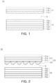
- a photovoltaic power generation module 10 having a multilayer structure of the prior art may have a solar cell module 15 installed on a building side and a transparent protective glass unit 11 installed on an exterior side of the building, and an air layer G may be formed between the solar cell module 15 and the protective glass unit 11.
- the protective glass unit 11 may include a color layer 11c on an incident light exit side of protective glass 11b, and an anti-reflection (AR) coating layer 11a may be provided on an incident light input side of the protective glass 11b.
- AR anti-reflection
- the solar cell module 15 may include a glass 15a, a sealing material 15b, a solar cell 15c, a sealing material 15d, and a back sheet 15e as illustrated in FIG. 1 .
- the glass 15a may protect the solar cell module 15 from physical damage and may increase transmittance of light such that sunlight may be transmitted to the solar cell 15c.
- the sealing materials 15b and 15d may protect the fragile solar cell 15c and a circuit from impact and may allow sunlight to pass therethrough, and may be mainly formed of ethylene-vinyl acetate (EVA).
- EVA ethylene-vinyl acetate
- the back sheet 15e may be disposed on a rear surface of the solar cell 15c to protect the solar cell 15c from external environments such as heat, humidity, and ultraviolet rays, and may also further improve efficiency of the solar cell module 15 through re-reflection of incoming sunlight.
- the photovoltaic power generation module 10 having a multilayer structure of the prior art may have a lot of difficulties in construction because the solar cell module 15 and the transparent protective glass 11 are provided as separate members.
- KR 101791130 B1 discloses a solar cell module, wherein the solar cell module has a plurality of solar cells, a plane on which sunlight is incident and which is disposed at a position spaced apart from the solar cells, a light collecting unit formed to collect and output the collected sunlight, and a reflecting unit formed to reflect the light between the solar cells, wherein the sunlight collected by the light collecting unit is confined between the light collecting unit and the reflecting unit.
- a reflective layer is formed on the light collecting part, and an air gap is formed between the light collecting part and the reflecting part.
- the present disclosure has been devised to solve at least some of the problems of the prior art described above, and may have a purpose of providing a photovoltaic power generation module which may reduce degradation of optical efficiency (securing transmittance at a positive viewing angle and securing reflectance at a negative viewing angle) of an optical pattern and may be configured to have a single layer structure.
- the present disclosure has a purpose of providing a photovoltaic power generation module which may decrease a reduction in a refractive effect generated between an optical pattern and an air layer.
- the present disclosure has a purpose of providing a photovoltaic power generation module which may maintain reflectance at a viewing angle of a lower side (ground) of a building to be an appropriate level or higher during a process for configuring the photovoltaic power generation module to have a single layer structure.
- the present disclosure provides a photovoltaic power generation module according to claim 1.
- the optical pattern may include an asymmetrical prism.
- the optical pattern may have a shape in which transmittance is higher and reflectance is lower at a viewing angle on one side than at a viewing angle on the other side with reference to a surface perpendicular to the base member.
- the gap may be configured to be within a range of 10 - 1000 um.
- the filler may include an acetate-based or silicone-based material.
- the supportive adhering part may include an optically clear adhesive (OCA).
- OCA optically clear adhesive
- an overall area of the supportive adhering part may be 3 - 20% of an area of the pattern member, and an overall area of the supportive adhering part may be 5 - 13% of an area of the pattern member.
- the supportive adhering part may include a light scattering agent.
- the light scattering agent may be included in the supportive adhering part by 5 - 60 weight%.
- the supportive adhering part may include a color pigment, and the color pigment may be included in the supportive adhering part by 3 - 30 weight%.
- the photovoltaic power generation module may include a glass for protecting the solar cell, and the filler may fill a space between the glass and the supportive adhering part.
- an effect in which degradation of optical efficiency (securing transmittance at a positive viewing angle and securing reflectance at a negative viewing angle) of an optical pattern may be reduced, and a single layer structure may be available may be obtained.
- reduction of a refraction effect generated between an optical pattern and an air layer may be decreased.
- an effect in which reflectance at a viewing angle of a lower side (ground) of a building may be maintained to be an appropriate level or higher during a process for providing a single layer structure may be obtained.
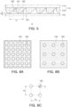
- a photovoltaic power generation module 100 may include a pattern glass 110 including a pattern member 120 having an optical pattern formed thereon, a solar cell module 130 having a solar cell 133, a plurality of supportive adhering parts 160 adhered to the pattern member 120 and each having a cylindrical shape, and a filler 150 filling a space between the supportive adhering part 160 and the solar cell module 130.
- the pattern glass 110 may include a base member 115, and a pattern member 120 provided in the base member 115 and having an optical pattern formed thereon.
- a color layer 113 may be formed on an incident light exit side of a protective glass 112, and an AR coating layer 111 may be provided on an incident light input side of the protective glass 112.
- a structure of the base member 115 is not limited thereto, and the color layer 113 or the AR coating layer 111 may not be provided, or another layer may be additionally formed.
- the pattern member 120 may be provided in the base member 115, and an optical pattern may be formed on the pattern member 120.
- the pattern member 120 may have a shape including an asymmetrical prism as in the example illustrated in FIGS. 4 and 5 , but a shape of the asymmetrical prism is not limited thereto.
- the pattern member 120 having an asymmetrical prism shape may have a shape in which a base portion 121 and a planar portion 124 are included, a short-surface portion 122 may be formed by a linear portion 122a and a curved portion 122b, and a long-surface portion 123 may be formed by two linear portions 123a and 123b, or as illustrated in FIG. 12B , the pattern member 120 may have a shape in which both the short-surface portion 122 and the long-surface portion 123 may be formed by linear lines, or as illustrated in FIG.
- the pattern member 120 may have a shape in which the short-surface portion 122 may be formed by a curved line and the long-surface portion 123 may be formed by a linear line, such that the pattern member 120 may have various shapes.
- FIGS. 5 and 12 illustrate an asymmetrical prism having a planar portion 125, but the pattern member 120 in the embodiment of the present disclosure may include an asymmetrical prism which does not have a planar portion.
- the optical pattern formed on the pattern member 120 may have a shape in which transmittance may be higher and reflectance may be lower at a viewing angle on one side than at a viewing angle on the other side with reference to a surface perpendicular to the base member 115.
- the configuration in which transmittance or reflectance may be high or low may be determined by comparing a maximum value or a minimum value of transmittance/reflectance at a viewing angle on one side and at a viewing angle on the other side.
- the optical pattern illustrated in FIGS. 4 and 5 may have a shape in which, with reference (a reference surface) to a surface perpendicular to the base member 115, when light is incident in a direction inclined to the left side from the reference surface, transmittance may be higher and reflectance may be lower than when light is incident in a direction inclined to the right side from the reference surface (the configuration will be described later with reference to FIGS. 8A and 8B ).
- transmittance of light incident from the left side may increase such that the amount of light transmitted to the solar cell 133 may increase, and as transmittance of light incident from the right side (a lower side) is relatively low and reflectance thereof is relatively high, an unnecessary increase of transmittance of gaze light transmitted to an observer located on the right side (a lower side) may be prevented (the configuration is disclosed in the patent application No. 2017-0105067 filed by the present inventor on August 17, 2017 , and the disclosure of the above application is included in this specification as a reference).
- the pattern member 120 may have a shape in which, with reference to a surface perpendicular to the base member 115, when light is incident in a direction inclined to the left side, transmittance may be higher and reflectance may be lower than when light is incident in a direction inclined to the right side.
- the solar cell module 130 may include a solar cell 133.
- the solar cell module 130 may include a glass 131, a sealing material 132, a solar cell 133, a sealing material 134, and a back sheet 135 as in the example illustrated in FIG. 4 , but when the solar cell module 130 includes the solar cell 133, a specific structure thereof may not be limited to the example illustrated in FIG. 4 . For example, an additional layer may be added.
- the glass 131 may protect the solar cell module 130 from physical damage and may increase transmittance of light such that sunlight may be transmitted to the solar cell 133.
- the sealing materials 132 and 134 may protect the fragile solar cell 133 and the circuit from impact, and may be configured to transmit sunlight, and may be mainly formed of ethylene vinyl acetate (EVA).
- EVA ethylene vinyl acetate
- the back sheet 135 may be disposed on a rear surface of the solar cell 133 to protect the solar cell 133 from external environments such as heat, humidity, and ultraviolet rays, and may further improve efficiency of the solar cell module 130 through re-reflection of incoming sunlight.
- the supportive adhering part 160 may be adhered to the pattern member 120 and may be configured to have a cylindrical shape. Also, the supportive adhering part 160 may allow the pattern glass 110 and the solar cell module 130 to be integrated with each other along with the filler 150 which will be described later.
- the supportive adhering part 160 may include an optically clear adhesive (OCA).
- OCA optically clear adhesive
- An OCA may be an optical-use transparent adhesive, and may have high transmissibility and may increase a thickness (a height) such that an OCA may function as an adhesive and a support.
- An OCA may have a refractive index of about 1.5-1.6, and may be attached to a cured pattern member 120 in certain pattern.
- a shape of the supportive adhering part 160 is illustrated as a cylinder having a circular cross-sectional surface.
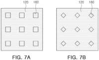
- the supportive adhering part 160 may have a rectangular cross-sectional surface as illustrated in FIG. 7A , and may have a rhombus-shaped cross-sectional surface as illustrated in FIG. 7B .
- the filler 150 may fill a space between the supportive adhering part 160 and the solar cell module 130, and may be used with the supportive adhering part 160 such that the pattern glass 110 and the solar cell module 130 may be integrated.
- the filler 150 may fill a space between the glass 131 and the supportive adhering part 160.
- the filler 150 may include an acetate-based or silicon-based materials.
- the acetate-based material may include ethylene-vinyl acetate (EVA).
- EVA ethylene-vinyl acetate
- a refractive index of the filler 150 may be approximately 1.5-1.6.
- one side of the filler 150 may be coupled to the supportive adhering part 160, and the other side may be coupled to the solar cell module 130.
- the filling material 150 may be used with the supportive adhering part 160 to combine the pattern glass 110 and the solar cell module 130 such that the photovoltaic power generation module 100 having a single layer structure may be manufactured.
- the solar cell module 130 may not include the glass 131, or the glass 131 and the sealing material 132, and in this case, one side of the filler 150 may be coupled to the supportive adhering part 160, and the other side may be coupled to the sealing material 132 of the solar cell module 130 or the solar cell 133.
- a height of the supportive adhering part 160 may be configured to be greater than a height of the pattern member 120 such that a gap h for forming an air layer between the filler 150 and the pattern member 120 may be formed.
- optical performance of the pattern member 120 may be maintained similarly to that of the photovoltaic power generation module 20 having a multilayer structure illustrated in FIG. 2 , which will be described later.
- the gap h for forming an air layer between the filler 150 and the pattern member 120 may be configured to be within a range of 10 - 1000 um preferably.
- the gap h for an air layer may have an extremely small size, but when the gap h is less than 10pm, the pattern member 120 and the filler 150 may be partially in contact with each other due to tolerance in a manufacturing process. Thus, the gap h may be 10pm or greater preferably. Also, when the gap h exceeds 1000 ⁇ m, a height (a thickness) of the supportive adhering part 160 may excessively increase such that a sufficient weight may not be supported. Thus, the gap h may be 1000 um(1mm) or less preferably.
- the supportive adhering part 160 may be attached to the cured pattern member 120 in certain pattern.
- an adhesive such as an OCA may be formed as a pattern and a cylindrical shape may be formed on the pattern member 120, and the adhesive may be UV (infrared) cured. Thereafter, the fully-cured or semicured supportive adhering part 160 may be attached to the filler 150.
- a portion 161 of the supportive adhering part 160 may be adhered to the pattern member 120, the other portion 162 may be attached to the filler 150, and a portion 163 of a side surface of the supportive adhering part 160 may be in contact with an air layer.
- refractive indexes of the supportive adhering part 160, the filler 150, and the pattern member 120 may be about 1.5-1.6, there may be no significant difference among the refractive indexes. Accordingly, total reflection may rarely occur in a region in which the supportive adhering part 160 is adhered to the pattern member 120 such that transmissivity may increase and reflectance may decrease.
- an area of the supportive adhering part 160 increases, an area in contact with the pattern member 120 may also increase such that optical performance of the pattern member 120 may degrade.
- transmittance may increase and reflectance may decrease as illustrated in FIG. 6B as compared to the case in which the supportive adhering part 160 is installed in a narrow area, which may cause an aesthetic problem for an observer at a viewing angle from a lower side.
- D a diameter of the supportive adhering part
- Px a spacing distance of the supportive adhering part in a horizontal direction
- Py a spacing distance of the supportive adhering part in a vertical direction.
- FIGS. 8A and 8B are a graph showing comparison of transmittance and reflectance with a first comparative example having a multilayer structure illustrated in FIG. 2 while changing an area ratio of the supportive adhering part 160 to the photovoltaic power generation module 100 having a single layer structure of an embodiment of the present disclosure illustrated in FIG. 4 .
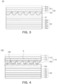
- a photovoltaic power generation module 20 of a first comparative example illustrated in FIG. 2 and a photovoltaic power generation module 30 of a second comparative example illustrated in FIG. 3 were configured to have substantially the same configuration as that of the photovoltaic power generation module 100 illustrated in FIG. 4 .
- a pattern glass 23 of the photovoltaic power generation module 20 illustrated in FIG. 2 may include a base member 21 having an AR coating layer 21a, a protective glass 21b, and a color layer 21c, and a pattern member 22.
- a pattern glass 33 of the photovoltaic power generation module 30 illustrated in FIG. 3 may include a base member 31 having an AR coating layer 31a, a protective glass 31b, and a color layer 31c, and a pattern member 32. The elements of each of the pattern glass 23 in FIG. 2 and the pattern glass 33 in FIG.
- 3 may correspond to the base member 115 having the AR coating layer 111, the protective glass 112, and the color layer 113, and the pattern member 120, respectively, included in the pattern glass 110 of the photovoltaic power generation module 100 illustrated in FIG. 4 , and the corresponding elements were configured to have the same shape, material, and optical properties.
- a solar cell module 25 of the photovoltaic module 20 illustrated in FIG. 2 may include a glass 25a, a sealing material 25b, a solar cell 25c, a sealing material 25d, and a back sheet 25e.
- a solar cell module 35 of the photovoltaic power generation module 30 illustrated in FIG. 3 may include a glass 35a, a sealing material 35b, a solar cell 35c, a sealing material 35d, and a back sheet 35e.
- the elements provided in the solar cell module 25 of FIG. 2 and the solar cell module 35 of FIG. 3 may correspond to the glass 131, the sealing material 132, the solar cell 133, the sealing material 134, and the back sheet 135 included in the solar cell module 130 of the photovoltaic power generation module 100 illustrated in FIG. 4 .
- an air gap G may be formed between the pattern glass 23 and the solar cell module 25, and in the photovoltaic power generation module 30 in FIG. 3 , a filler 37 was configured to entirely fill a space between the pattern glass 33 and the solar cell module 35 to form a single layer structure.
- a viewing angle of when light is incident in a direction inclined to the left side from the reference surface by a certain angle may be indicated as positive (+), and a viewing angle of when light is incident in a direction inclined to the right side from the reference surface by a certain angle may be indicated as negative (-).
- a negative (-) viewing angle area of the left side may indicate transmittance and reflectance of light incident from the right side (a lower side of a building)
- a positive (+) viewing angle area of the right side may indicate transmittance and reflectance of light incident from the left side (an upper side of a building), in the graphs in FIGS. 8A and 8B .
- transmittance at a viewing angle of the upper side (positive) of a building may be higher than transmittance at a viewing angle of the lower side (negative) of the building, and on the contrary, reflectance at a viewing angle of the lower side of the building may be higher than reflectance at a viewing angle of the upper side of the building.
- transmittance of light incident in an upper side direction (positive viewing angle) of the building may be high such that the amount of light transmitted to the solar cell 133 may increase, and as transmittance of light incident in a lower side direction (negative viewing angle) of the building may be relatively low and reflectance may be relatively high such that an unnecessary increase of transmittance of gaze light transmitted to an observer positioned on the lower side of the building may be prevented.
- the first comparative example (multilayer structure) illustrated in FIG. 2 has a multilayer structure, workability and assembling properties may significantly degrade, which may be a problem.
- the filler 37 When a shape in which the filler 37 entirely fills a space between the pattern glass 33 and the solar cell module 35 as in the second comparative example illustrated in FIG. 3 so as to change a structure of the first comparative example (multilayer structure) illustrated in FIG. 2 to be a single layer structure is included, there may be almost no difference in refractive indexes between the pattern member 32 having a refractive index of about 1.5-1.6 and the filler 37 (e.g., EVA) having a refractive index of about 1.5-1.6. Accordingly, it may be difficult for total reflection to occur on a boundary surface between the pattern member 32 and the filler 37.
- EVA e.g., EVA
- an optical pattern of the pattern member 32 which was configured in consideration of transmittance and reflectance according to a viewing angle may not be able to perform an optical function, and accordingly, transmittance in a lower side direction (negative viewing angle) of the building may increase, but reflectance of light incident in the lower side direction of the building may rapidly decrease, which may cause an aesthetic problem to an observer.
- FIGS. 8A and 8B it has been indicated that, when an area ratio of the supportive adhering part 160 was configured differently and was compared with that of the first comparative example (multilayer structure) illustrated in FIG. 2 , the more the area ratio of the supportive adhering part 160 increased, the more the transmittance increased and reflectance decreased.
- the multilayer structure of the first comparative example illustrated in FIG. 2 may be changed to a single layer structure without a significant difference in optical performance.
- transmittance which is not significantly different from that of a multilayer structure in an upper side direction (positive viewing angle) of the building, and reflectance which is not greatly decreased from that of the multilayer structure in a lower side direction (negative viewing angle) of the building may be necessary.
- an overall area of the supportive adhering part 160 may be 3 - 20% of an area of the pattern member 120 preferably.
- the area ratio When the area ratio is 20% or higher, reflectance may be less than 25% in a lower side direction (negative viewing angle) of the building such that there may be an aesthetic problem to an observer, and when the area ratio is less than 3%, there may be a problem in which adhesion performance and support performance of the supportive adhering part 160 may degrade. Particularly, when the area ratio is less than 3%, there may be a problem in which the supportive adhering part 160 may be deformed such that the supportive adhering part 160 may not support a weight of the pattern glass 110.
- An overall area of the supportive adhering part 160 may be 5 - 13% of an area of the pattern member 120 preferably.
- adhesion performance and support performance of the supportive adhering part 160 may be sufficiently secured, and transmittance and reflectance may be maintained to be similar to transmittance at a positive viewing angle and reflectance at a negative viewing angle of a multilayer structure.
- the photovoltaic power generation module 100 in the embodiment of the present disclosure may improve workability and assembling properties by configuring the multilayer structure as in the first comparative example illustrated in FIG. 2 to be a single layer structure, and an effect in which there may be no significant difference in terms of optical properties as compared to the multilayer structure as in the first comparative example illustrated in FIG. 2 may be obtained.
- FIGS. 9 and 11 a photovoltaic power generation module 100 according to another example embodiment will be described with reference to FIGS. 9 and 11 .
- the photovoltaic power generation module 100 illustrated in FIG. 9 may have the same configuration as in the embodiment illustrated in FIGS. 4 and 5 other than the configuration in which the supportive adhering part 160 may further include a light scattering agent 165.
- the detailed descriptions of the same or similar elements will not be provided to avoid unnecessary overlapping description.
- the light scattering agent 165 may scatter incident light such that transmittance may decrease, and reflectance may increase.
- the light scattering agent 165 polymer particle or a polymer material such as a haze ball may be used, but a type of the light scattering agent 165 is not limited thereto.
- transmittance and reflectance may be adjusted.
- FIGS. 10A and 10B illustrate changes in transmittance and reflectance according to changes in weight ratio (wt%) of a light scattering agent to a total weight of the supportive adhering part 160 including the light scattering agent 165.
- a TiO2 haze ball having a refractive index of 2.1 was used, and only a weight ratio was configured differently.
- the light scattering agent 165 may be included in the supportive adhering part by 5 - 60 weight% preferably.
- a weight ratio of the light scattering agent is less than 5 wt%, an effect of scattering may not be significant such that an effect of compensation for a refractive index may not be significant.
- the weight ratio exceeds 60wt%, reflectance at a negative viewing angle may be sufficiently secured, but an adhesive ratio of the supportive adhering part 160 may decrease such that it may be difficult for the supportive adhering part 160 to perform a function as a support and an adhesive.
- the supportive adhering part 160 may include a color pigment (dye) instead of the light scattering agent 165.
- a color pigment die
- a scattering effect and an effect of increase of reflectance may be obtained.
- the color pigment may be included in the supportive adhering part 160 by 3 - 30 weight% preferably.
- a reference concentration refers to a case in which the supportive adhering part 160 includes 3 weight% of the color pigment.
- the scattering and an effect of increase of reflectance at a negative viewing angle according to the scattering may not be significant.
- the color pigment exceeds 30wt%, an increase of reflectance may not be greatly resolved and there may be a limitation in support and adhesion performance of the supportive adhering part 160, and costs may increase, which may be a problem.
Landscapes
- Photovoltaic Devices (AREA)
Claims (12)
- Photovoltaisches Stromerzeugungsmodul (100), umfassend:ein Musterglas (110) mit einem Basiselement (115) und einem Musterelement (120), das auf dem Basiselement (115) vorgesehen ist und ein darauf ausgebildetes optisches Muster enthält;ein Solarzellenmodul (130) mit einer Solarzelle (133);eine Vielzahl von stützenden Klebeteilen (160), die an dem Musterelement (120) haften und jeweils eine zylindrische Form mit einer Achse haben, die senkrecht zu dem Musterglas (110) ist; undeinen Füllstoff (150), der einen Raum zwischen dem stützenden Klebeteil (160) und dem Solarzellenmodul (130) ausfüllt,wobei das Musterglas (110) und das Solarzellenmodul (130) durch den stützenden Klebeteil (160) und den Füllstoff (150) miteinander integriert sind, undwobei eine Höhe des stützenden Klebeteils (160) so ausgebildet ist, dass sie höher ist als eine Höhe des Musterelements (120), so dass ein Spalt (h) zum Bilden einer Luftschicht zwischen dem Musterelement (120) und dem Füllstoff (150) vorgesehen ist, dadurch gekennzeichnet, dass das photovoltaische Stromerzeugungsmodul (100) ein Glas (131) in dem Solarzellenmodul (130) zum Schützen der Solarzelle (133) enthält, und dass der Füllstoff (150) einen Raum zwischen dem Glas (131) und dem stützenden Klebeteil (160) ausfüllt.
- Photovoltaisches Stromerzeugungsmodul (100) nach Anspruch 1, wobei das optische Muster ein asymmetrisches Prisma umfasst.
- Photovoltaisches Stromerzeugungsmodul (100) nach Anspruch 1, wobei das optische Muster eine Form hat, bei der die Durchlässigkeit bezogen auf eine zum Basiselement (115) senkrechte Fläche höher und die Reflexion niedriger bei einem Betrachtungswinkel auf einer Seite als bei einem Betrachtungswinkel auf der anderen Seite ist,
- Photovoltaisches Stromerzeugungsmodul (100) nach Anspruch 1, wobei der Spalt (h) in einem Bereich von 10-1000 µm liegt.
- Photovoltaisches Stromerzeugungsmodul (100) nach Anspruch 1, wobei der Füllstoff (150) ein Material auf Acetat- oder Silikonbasis enthält.
- Photovoltaisches Stromerzeugungsmodul (100) nach Anspruch 1, wobei der stützende Klebeteil (160) einen optisch klaren Klebstoff (OCA) enthält.
- Photovoltaisches Stromerzeugungsmodul (100) nach einem der Ansprüche 1 bis 6, wobei bei Betrachtung auf eine ebene Oberfläche eine Gesamtfläche des stützenden Klebeteils (160) 3-20 % einer Fläche des Musterelements (120) beträgt.
- Photovoltaisches Stromerzeugungsmodul (100) nach einem der Ansprüche 1 bis 6, wobei bei Betrachtung auf eine ebene Oberfläche eine Gesamtfläche des stützenden Haftteils (160) 5-13 % einer Fläche des Musterelements (120) beträgt.
- Photovoltaisches Stromerzeugungsmodul (100) nach einem der Ansprüche 1 bis 6, wobei der stützende Haftteil (160) ein Lichtstreumittel (165) enthält.
- Photovoltaisches Stromerzeugungsmodul (100) nach Anspruch 9, wobei das Lichtstreumittel (165) in dem stützenden Haftteil (160) mit 5-60 Gew.-% enthalten ist.
- Photovoltaisches Stromerzeugungsmodul (100) nach einem der Ansprüche 1 bis 6, wobei der stützende Haftteil (165) ein Farbpigment enthält.
- Photovoltaisches Stromerzeugungsmodul (100) nach Anspruch 11, wobei das Farbpigment in dem stützenden Haftteil (160) mit 3-30 Gew.-% enthalten ist.
Applications Claiming Priority (2)
| Application Number | Priority Date | Filing Date | Title |
|---|---|---|---|
| KR1020170180272A KR101982588B1 (ko) | 2017-12-26 | 2017-12-26 | 태양광 발전모듈 |
| PCT/KR2018/015517 WO2019132307A1 (ko) | 2017-12-26 | 2018-12-07 | 태양광 발전모듈 |
Publications (4)
| Publication Number | Publication Date |
|---|---|
| EP3734670A1 EP3734670A1 (de) | 2020-11-04 |
| EP3734670A4 EP3734670A4 (de) | 2021-03-03 |
| EP3734670B1 true EP3734670B1 (de) | 2023-05-17 |
| EP3734670B8 EP3734670B8 (de) | 2023-06-28 |
Family
ID=66679073
Family Applications (1)
| Application Number | Title | Priority Date | Filing Date |
|---|---|---|---|
| EP18894967.1A Active EP3734670B8 (de) | 2017-12-26 | 2018-12-07 | Fotovoltaisches energieerzeugungsmodul |
Country Status (5)
| Country | Link |
|---|---|
| US (1) | US11251322B2 (de) |
| EP (1) | EP3734670B8 (de) |
| KR (1) | KR101982588B1 (de) |
| CN (1) | CN111771288B (de) |
| WO (1) | WO2019132307A1 (de) |
Families Citing this family (5)
| Publication number | Priority date | Publication date | Assignee | Title |
|---|---|---|---|---|
| KR102209403B1 (ko) | 2018-12-11 | 2021-02-01 | 주식회사 포스코 | 다공성 폴리실록산 필름 제조방법, 이에 의해 제조된 다공성 폴리실록산 필름 및 이를 포함하는 태양광 모듈 |
| US11791762B2 (en) * | 2020-11-23 | 2023-10-17 | Yaue-Sheng Chang | Solar panel for pitched roof and construction method thereof |
| KR102501442B1 (ko) * | 2020-12-21 | 2023-02-20 | 재단법인 포항산업과학연구원 | 광학패턴이 포함된 컬러필름의 제조방법 및 상기 컬러필름을 포함하는 태양광 발전 모듈 |
| CN114597279A (zh) * | 2022-02-25 | 2022-06-07 | 中能创光电科技(常州)有限公司 | 带图案的光伏组件及其制备方法 |
| CN117117015B (zh) * | 2023-08-10 | 2024-03-15 | 广东南星玻璃有限公司 | 一种真空光伏装饰玻璃及其真空结构 |
Family Cites Families (28)
| Publication number | Priority date | Publication date | Assignee | Title |
|---|---|---|---|---|
| US4379202A (en) * | 1981-06-26 | 1983-04-05 | Mobil Solar Energy Corporation | Solar cells |
| JP4330241B2 (ja) * | 2000-02-18 | 2009-09-16 | 三洋電機株式会社 | 太陽電池モジュール |
| JP3805996B2 (ja) * | 2001-04-20 | 2006-08-09 | シャープ株式会社 | 採光型合わせガラス構造太陽電池モジュール及び採光型複層構造太陽電池モジュール |
| US20080000517A1 (en) * | 2003-06-10 | 2008-01-03 | Gonsiorawski Ronald C | Photovoltaic module with light reflecting backskin |
| US20090194156A1 (en) * | 2008-02-01 | 2009-08-06 | Grommesh Robert C | Dual seal photovoltaic glazing assembly and method |
| KR101057790B1 (ko) | 2009-02-03 | 2011-08-19 | 테라웨이브 주식회사 | 집광형 태양광 발전 모듈 |
| KR101180234B1 (ko) * | 2009-04-03 | 2012-09-05 | (주)엘지하우시스 | 디자인층을 구비한 건물 일체형 태양전지 모듈 |
| DE102009049228A1 (de) * | 2009-10-13 | 2011-08-04 | Fraunhofer-Gesellschaft zur Förderung der angewandten Forschung e.V., 80686 | Vorrichtung zur Konzentrierung und Umwandlung von Solarenergie |
| JP5745776B2 (ja) | 2010-03-15 | 2015-07-08 | デクセリアルズ株式会社 | 光学積層体および建具 |
| KR20130109929A (ko) | 2010-04-06 | 2013-10-08 | 오와이 아이씨에스 인텔리전트 컨트롤 시스템즈 리미티드 | 태양전지를 이용하기 위한 매립된 공동을 갖는 라미네이트 구조 및 이들의 관련 제조 방법 |
| CN103025410B (zh) | 2010-07-07 | 2015-02-18 | 三菱丽阳株式会社 | 中空纤维膜的干燥装置及干燥方法 |
| CN102376811A (zh) * | 2010-08-23 | 2012-03-14 | 杜邦太阳能有限公司 | 光伏面板 |
| KR101616131B1 (ko) * | 2010-10-05 | 2016-04-27 | 엘지전자 주식회사 | 태양전지 모듈 |
| US9281186B2 (en) * | 2011-03-31 | 2016-03-08 | Ats Automation Tooling Systems Inc. | Colored photovoltaic modules and methods of construction |
| KR20130030390A (ko) | 2011-09-19 | 2013-03-27 | 현대중공업 주식회사 | 건축물에 설치되는 지/지 타입 태양광모듈 |
| JP2013149803A (ja) * | 2012-01-19 | 2013-08-01 | Keiwa Inc | 太陽電池モジュール用フロントシート及びこれを用いた太陽電池モジュール |
| KR101307015B1 (ko) | 2013-03-19 | 2013-09-11 | 주식회사 에이치와이티씨 | 고투과 열차폐 조성물을 이용한 태양전지용 커버 글라스 도막 구조 |
| JP2015153836A (ja) * | 2014-02-12 | 2015-08-24 | シャープ株式会社 | 太陽電池モジュール、太陽光発電装置 |
| KR101497941B1 (ko) | 2014-03-24 | 2015-03-03 | 광주과학기술원 | 태양전지 모듈 및 이의 제조방법 |
| NL2013168B1 (en) * | 2014-07-11 | 2016-09-09 | Stichting Energieonderzoek Centrum Nederland | Solar panel and method of manufacturing such a solar panel. |
| US20160276501A1 (en) * | 2015-03-16 | 2016-09-22 | Bright New World Ab | Solar panel converter layer |
| JP6728597B2 (ja) * | 2015-08-25 | 2020-07-22 | 大日本印刷株式会社 | 太陽電池複合型表示体 |
| KR101682133B1 (ko) | 2015-11-09 | 2016-12-02 | 한국과학기술연구원 | 나노패턴 내에 양자점이 임베디드된 광학 필름, 이의 제조방법 및 이를 이용한 태양전지 |
| JP6608690B2 (ja) | 2015-12-09 | 2019-11-20 | 株式会社ヤシマ精工 | 2色成形品 |
| JP6720651B2 (ja) * | 2016-03-31 | 2020-07-08 | 大日本印刷株式会社 | 太陽電池複合型表示体 |
| KR101791130B1 (ko) | 2016-11-18 | 2017-10-27 | 엘지전자 주식회사 | 태양전지 모듈 |
| KR101940921B1 (ko) | 2017-08-18 | 2019-01-22 | 주식회사 포스코 | 패턴글라스 및 이를 포함하는 태양광 발전모듈 |
| KR101917533B1 (ko) | 2017-08-31 | 2018-11-09 | 주식회사 포스코 | 컬러 태양광 모듈 |
-
2017
- 2017-12-26 KR KR1020170180272A patent/KR101982588B1/ko active Active
-
2018
- 2018-12-07 WO PCT/KR2018/015517 patent/WO2019132307A1/ko not_active Ceased
- 2018-12-07 CN CN201880090307.1A patent/CN111771288B/zh active Active
- 2018-12-07 US US16/964,350 patent/US11251322B2/en active Active
- 2018-12-07 EP EP18894967.1A patent/EP3734670B8/de active Active
Also Published As
| Publication number | Publication date |
|---|---|
| EP3734670A4 (de) | 2021-03-03 |
| EP3734670A1 (de) | 2020-11-04 |
| KR101982588B1 (ko) | 2019-05-27 |
| US11251322B2 (en) | 2022-02-15 |
| US20210036172A1 (en) | 2021-02-04 |
| CN111771288B (zh) | 2023-10-20 |
| EP3734670B8 (de) | 2023-06-28 |
| WO2019132307A1 (ko) | 2019-07-04 |
| CN111771288A (zh) | 2020-10-13 |
Similar Documents
| Publication | Publication Date | Title |
|---|---|---|
| EP3734670B1 (de) | Fotovoltaisches energieerzeugungsmodul | |
| US8482691B2 (en) | Display apparatus having a minimized non-display region | |
| KR102255145B1 (ko) | 반투과형 반사 시트, 도광판 및 표시 장치 | |
| US8045272B2 (en) | Display apparatus | |
| US8054554B2 (en) | Display apparatus | |
| US20120019758A1 (en) | Display device | |
| WO2006030823A1 (ja) | 視野角制御シート及び表示装置 | |
| EP2106252A2 (de) | Nachtsichtgläser | |
| US8072682B2 (en) | Transmissive screen and diffusion plate | |
| JP2021033019A (ja) | 光学部材 | |
| CN106443861A (zh) | 一种光学膜及触控显示屏 | |
| JP6874322B2 (ja) | 反射スクリーン、映像表示装置 | |
| US12130429B2 (en) | Head-up display screen, head-up display assembly, and vehicle | |
| KR101982589B1 (ko) | 태양광 발전모듈 | |
| US8023194B2 (en) | Display apparatus | |
| US8829340B2 (en) | Solar light-control module | |
| US20060103768A1 (en) | Front filter of display panel and fabrication method thereof | |
| CN219065950U (zh) | Ec片和波导片贴合模组 | |
| CN219065948U (zh) | Ec模组 | |
| JP2002214570A (ja) | 眼鏡用レンズ及びその製造方法 | |
| KR20100000779A (ko) | 디스플레이 장치용 시야각 조정 필터 및 이를 구비하는디스플레이 장치 | |
| JP7255248B2 (ja) | 光学部材 | |
| CN112526647A (zh) | 镀膜衬底及显示系统 | |
| JP2011145092A (ja) | 車両用計器 | |
| KR102250858B1 (ko) | 김서림 방지기능을 가진 고해상도 렌즈유닛 및 이를 포함하는 고글 |
Legal Events
| Date | Code | Title | Description |
|---|---|---|---|
| STAA | Information on the status of an ep patent application or granted ep patent |
Free format text: STATUS: THE INTERNATIONAL PUBLICATION HAS BEEN MADE |
|
| PUAI | Public reference made under article 153(3) epc to a published international application that has entered the european phase |
Free format text: ORIGINAL CODE: 0009012 |
|
| STAA | Information on the status of an ep patent application or granted ep patent |
Free format text: STATUS: REQUEST FOR EXAMINATION WAS MADE |
|
| 17P | Request for examination filed |
Effective date: 20200723 |
|
| AK | Designated contracting states |
Kind code of ref document: A1 Designated state(s): AL AT BE BG CH CY CZ DE DK EE ES FI FR GB GR HR HU IE IS IT LI LT LU LV MC MK MT NL NO PL PT RO RS SE SI SK SM TR |
|
| AX | Request for extension of the european patent |
Extension state: BA ME |
|
| A4 | Supplementary search report drawn up and despatched |
Effective date: 20210129 |
|
| RIC1 | Information provided on ipc code assigned before grant |
Ipc: H01L 31/0232 20140101AFI20210125BHEP Ipc: H01L 31/048 20140101ALI20210125BHEP Ipc: H01L 31/054 20140101ALI20210125BHEP |
|
| DAV | Request for validation of the european patent (deleted) | ||
| DAX | Request for extension of the european patent (deleted) | ||
| GRAP | Despatch of communication of intention to grant a patent |
Free format text: ORIGINAL CODE: EPIDOSNIGR1 |
|
| STAA | Information on the status of an ep patent application or granted ep patent |
Free format text: STATUS: GRANT OF PATENT IS INTENDED |
|
| INTG | Intention to grant announced |
Effective date: 20220622 |
|
| GRAJ | Information related to disapproval of communication of intention to grant by the applicant or resumption of examination proceedings by the epo deleted |
Free format text: ORIGINAL CODE: EPIDOSDIGR1 |
|
| STAA | Information on the status of an ep patent application or granted ep patent |
Free format text: STATUS: REQUEST FOR EXAMINATION WAS MADE |
|
| STAA | Information on the status of an ep patent application or granted ep patent |
Free format text: STATUS: EXAMINATION IS IN PROGRESS |
|
| INTC | Intention to grant announced (deleted) | ||
| 17Q | First examination report despatched |
Effective date: 20221004 |
|
| RAP3 | Party data changed (applicant data changed or rights of an application transferred) |
Owner name: RESEARCH INSTITUTE OF INDUSTRIAL SCIENCE & TECHNOLOGY Owner name: POSCO HOLDINGS INC. |
|
| GRAP | Despatch of communication of intention to grant a patent |
Free format text: ORIGINAL CODE: EPIDOSNIGR1 |
|
| STAA | Information on the status of an ep patent application or granted ep patent |
Free format text: STATUS: GRANT OF PATENT IS INTENDED |
|
| INTG | Intention to grant announced |
Effective date: 20230109 |
|
| GRAS | Grant fee paid |
Free format text: ORIGINAL CODE: EPIDOSNIGR3 |
|
| GRAA | (expected) grant |
Free format text: ORIGINAL CODE: 0009210 |
|
| STAA | Information on the status of an ep patent application or granted ep patent |
Free format text: STATUS: THE PATENT HAS BEEN GRANTED |
|
| REG | Reference to a national code |
Ref country code: DE Ref legal event code: R081 Ref document number: 602018050063 Country of ref document: DE Owner name: RESEARCH INSTITUTE OF INDUSTRIAL SCIENCE & TEC, KR Free format text: FORMER OWNERS: POSCO HOLDINGS INC., SEOUL, KR; RESEARCH INSTITUTE OF INDUSTRIAL SCIENCE & TECHNOLOGY, POHANG-SI, GYEONGSANGBUK-DO, KR Ref country code: DE Ref legal event code: R081 Ref document number: 602018050063 Country of ref document: DE Owner name: POSCO CO., LTD, POHANG-SI, KR Free format text: FORMER OWNERS: POSCO HOLDINGS INC., SEOUL, KR; RESEARCH INSTITUTE OF INDUSTRIAL SCIENCE & TECHNOLOGY, POHANG-SI, GYEONGSANGBUK-DO, KR |
|
| AK | Designated contracting states |
Kind code of ref document: B1 Designated state(s): AL AT BE BG CH CY CZ DE DK EE ES FI FR GB GR HR HU IE IS IT LI LT LU LV MC MK MT NL NO PL PT RO RS SE SI SK SM TR |
|
| REG | Reference to a national code |
Ref country code: GB Ref legal event code: FG4D |
|
| RAP2 | Party data changed (patent owner data changed or rights of a patent transferred) |
Owner name: RESEARCH INSTITUTE OF INDUSTRIAL SCIENCE & TECHNOLOGY Owner name: POSCO CO., LTD |
|
| REG | Reference to a national code |
Ref country code: DE Ref legal event code: R096 Ref document number: 602018050063 Country of ref document: DE |
|
| REG | Reference to a national code |
Ref country code: CH Ref legal event code: PK Free format text: BERICHTIGUNG B8 Ref country code: CH Ref legal event code: EP |
|
| REG | Reference to a national code |
Ref country code: IE Ref legal event code: FG4D |
|
| REG | Reference to a national code |
Ref country code: AT Ref legal event code: REF Ref document number: 1568769 Country of ref document: AT Kind code of ref document: T Effective date: 20230615 |
|
| REG | Reference to a national code |
Ref country code: NL Ref legal event code: FP |
|
| REG | Reference to a national code |
Ref country code: LT Ref legal event code: MG9D |
|
| REG | Reference to a national code |
Ref country code: AT Ref legal event code: MK05 Ref document number: 1568769 Country of ref document: AT Kind code of ref document: T Effective date: 20230517 |
|
| PG25 | Lapsed in a contracting state [announced via postgrant information from national office to epo] |
Ref country code: SE Free format text: LAPSE BECAUSE OF FAILURE TO SUBMIT A TRANSLATION OF THE DESCRIPTION OR TO PAY THE FEE WITHIN THE PRESCRIBED TIME-LIMIT Effective date: 20230517 Ref country code: PT Free format text: LAPSE BECAUSE OF FAILURE TO SUBMIT A TRANSLATION OF THE DESCRIPTION OR TO PAY THE FEE WITHIN THE PRESCRIBED TIME-LIMIT Effective date: 20230918 Ref country code: NO Free format text: LAPSE BECAUSE OF FAILURE TO SUBMIT A TRANSLATION OF THE DESCRIPTION OR TO PAY THE FEE WITHIN THE PRESCRIBED TIME-LIMIT Effective date: 20230817 Ref country code: ES Free format text: LAPSE BECAUSE OF FAILURE TO SUBMIT A TRANSLATION OF THE DESCRIPTION OR TO PAY THE FEE WITHIN THE PRESCRIBED TIME-LIMIT Effective date: 20230517 Ref country code: AT Free format text: LAPSE BECAUSE OF FAILURE TO SUBMIT A TRANSLATION OF THE DESCRIPTION OR TO PAY THE FEE WITHIN THE PRESCRIBED TIME-LIMIT Effective date: 20230517 |
|
| PG25 | Lapsed in a contracting state [announced via postgrant information from national office to epo] |
Ref country code: RS Free format text: LAPSE BECAUSE OF FAILURE TO SUBMIT A TRANSLATION OF THE DESCRIPTION OR TO PAY THE FEE WITHIN THE PRESCRIBED TIME-LIMIT Effective date: 20230517 Ref country code: PL Free format text: LAPSE BECAUSE OF FAILURE TO SUBMIT A TRANSLATION OF THE DESCRIPTION OR TO PAY THE FEE WITHIN THE PRESCRIBED TIME-LIMIT Effective date: 20230517 Ref country code: LV Free format text: LAPSE BECAUSE OF FAILURE TO SUBMIT A TRANSLATION OF THE DESCRIPTION OR TO PAY THE FEE WITHIN THE PRESCRIBED TIME-LIMIT Effective date: 20230517 Ref country code: LT Free format text: LAPSE BECAUSE OF FAILURE TO SUBMIT A TRANSLATION OF THE DESCRIPTION OR TO PAY THE FEE WITHIN THE PRESCRIBED TIME-LIMIT Effective date: 20230517 Ref country code: IS Free format text: LAPSE BECAUSE OF FAILURE TO SUBMIT A TRANSLATION OF THE DESCRIPTION OR TO PAY THE FEE WITHIN THE PRESCRIBED TIME-LIMIT Effective date: 20230917 Ref country code: HR Free format text: LAPSE BECAUSE OF FAILURE TO SUBMIT A TRANSLATION OF THE DESCRIPTION OR TO PAY THE FEE WITHIN THE PRESCRIBED TIME-LIMIT Effective date: 20230517 Ref country code: GR Free format text: LAPSE BECAUSE OF FAILURE TO SUBMIT A TRANSLATION OF THE DESCRIPTION OR TO PAY THE FEE WITHIN THE PRESCRIBED TIME-LIMIT Effective date: 20230818 |
|
| PG25 | Lapsed in a contracting state [announced via postgrant information from national office to epo] |
Ref country code: FI Free format text: LAPSE BECAUSE OF FAILURE TO SUBMIT A TRANSLATION OF THE DESCRIPTION OR TO PAY THE FEE WITHIN THE PRESCRIBED TIME-LIMIT Effective date: 20230517 |
|
| PG25 | Lapsed in a contracting state [announced via postgrant information from national office to epo] |
Ref country code: SK Free format text: LAPSE BECAUSE OF FAILURE TO SUBMIT A TRANSLATION OF THE DESCRIPTION OR TO PAY THE FEE WITHIN THE PRESCRIBED TIME-LIMIT Effective date: 20230517 |
|
| PG25 | Lapsed in a contracting state [announced via postgrant information from national office to epo] |
Ref country code: SM Free format text: LAPSE BECAUSE OF FAILURE TO SUBMIT A TRANSLATION OF THE DESCRIPTION OR TO PAY THE FEE WITHIN THE PRESCRIBED TIME-LIMIT Effective date: 20230517 Ref country code: SK Free format text: LAPSE BECAUSE OF FAILURE TO SUBMIT A TRANSLATION OF THE DESCRIPTION OR TO PAY THE FEE WITHIN THE PRESCRIBED TIME-LIMIT Effective date: 20230517 Ref country code: RO Free format text: LAPSE BECAUSE OF FAILURE TO SUBMIT A TRANSLATION OF THE DESCRIPTION OR TO PAY THE FEE WITHIN THE PRESCRIBED TIME-LIMIT Effective date: 20230517 Ref country code: EE Free format text: LAPSE BECAUSE OF FAILURE TO SUBMIT A TRANSLATION OF THE DESCRIPTION OR TO PAY THE FEE WITHIN THE PRESCRIBED TIME-LIMIT Effective date: 20230517 Ref country code: DK Free format text: LAPSE BECAUSE OF FAILURE TO SUBMIT A TRANSLATION OF THE DESCRIPTION OR TO PAY THE FEE WITHIN THE PRESCRIBED TIME-LIMIT Effective date: 20230517 Ref country code: CZ Free format text: LAPSE BECAUSE OF FAILURE TO SUBMIT A TRANSLATION OF THE DESCRIPTION OR TO PAY THE FEE WITHIN THE PRESCRIBED TIME-LIMIT Effective date: 20230517 |
|
| REG | Reference to a national code |
Ref country code: DE Ref legal event code: R097 Ref document number: 602018050063 Country of ref document: DE |
|
| PLBE | No opposition filed within time limit |
Free format text: ORIGINAL CODE: 0009261 |
|
| STAA | Information on the status of an ep patent application or granted ep patent |
Free format text: STATUS: NO OPPOSITION FILED WITHIN TIME LIMIT |
|
| 26N | No opposition filed |
Effective date: 20240220 |
|
| PG25 | Lapsed in a contracting state [announced via postgrant information from national office to epo] |
Ref country code: SI Free format text: LAPSE BECAUSE OF FAILURE TO SUBMIT A TRANSLATION OF THE DESCRIPTION OR TO PAY THE FEE WITHIN THE PRESCRIBED TIME-LIMIT Effective date: 20230517 |
|
| PG25 | Lapsed in a contracting state [announced via postgrant information from national office to epo] |
Ref country code: SI Free format text: LAPSE BECAUSE OF FAILURE TO SUBMIT A TRANSLATION OF THE DESCRIPTION OR TO PAY THE FEE WITHIN THE PRESCRIBED TIME-LIMIT Effective date: 20230517 Ref country code: IT Free format text: LAPSE BECAUSE OF FAILURE TO SUBMIT A TRANSLATION OF THE DESCRIPTION OR TO PAY THE FEE WITHIN THE PRESCRIBED TIME-LIMIT Effective date: 20230517 |
|
| PG25 | Lapsed in a contracting state [announced via postgrant information from national office to epo] |
Ref country code: LU Free format text: LAPSE BECAUSE OF NON-PAYMENT OF DUE FEES Effective date: 20231207 |
|
| PG25 | Lapsed in a contracting state [announced via postgrant information from national office to epo] |
Ref country code: MC Free format text: LAPSE BECAUSE OF FAILURE TO SUBMIT A TRANSLATION OF THE DESCRIPTION OR TO PAY THE FEE WITHIN THE PRESCRIBED TIME-LIMIT Effective date: 20230517 |
|
| GBPC | Gb: european patent ceased through non-payment of renewal fee |
Effective date: 20231207 |
|
| REG | Reference to a national code |
Ref country code: BE Ref legal event code: MM Effective date: 20231231 |
|
| PG25 | Lapsed in a contracting state [announced via postgrant information from national office to epo] |
Ref country code: MC Free format text: LAPSE BECAUSE OF FAILURE TO SUBMIT A TRANSLATION OF THE DESCRIPTION OR TO PAY THE FEE WITHIN THE PRESCRIBED TIME-LIMIT Effective date: 20230517 Ref country code: LU Free format text: LAPSE BECAUSE OF NON-PAYMENT OF DUE FEES Effective date: 20231207 |
|
| REG | Reference to a national code |
Ref country code: IE Ref legal event code: MM4A |
|
| PG25 | Lapsed in a contracting state [announced via postgrant information from national office to epo] |
Ref country code: IE Free format text: LAPSE BECAUSE OF NON-PAYMENT OF DUE FEES Effective date: 20231207 |
|
| PG25 | Lapsed in a contracting state [announced via postgrant information from national office to epo] |
Ref country code: GB Free format text: LAPSE BECAUSE OF NON-PAYMENT OF DUE FEES Effective date: 20231207 |
|
| PG25 | Lapsed in a contracting state [announced via postgrant information from national office to epo] |
Ref country code: BE Free format text: LAPSE BECAUSE OF NON-PAYMENT OF DUE FEES Effective date: 20231231 |
|
| PG25 | Lapsed in a contracting state [announced via postgrant information from national office to epo] |
Ref country code: FR Free format text: LAPSE BECAUSE OF NON-PAYMENT OF DUE FEES Effective date: 20231231 |
|
| PG25 | Lapsed in a contracting state [announced via postgrant information from national office to epo] |
Ref country code: IE Free format text: LAPSE BECAUSE OF NON-PAYMENT OF DUE FEES Effective date: 20231207 Ref country code: GB Free format text: LAPSE BECAUSE OF NON-PAYMENT OF DUE FEES Effective date: 20231207 Ref country code: FR Free format text: LAPSE BECAUSE OF NON-PAYMENT OF DUE FEES Effective date: 20231231 Ref country code: BE Free format text: LAPSE BECAUSE OF NON-PAYMENT OF DUE FEES Effective date: 20231231 |
|
| PG25 | Lapsed in a contracting state [announced via postgrant information from national office to epo] |
Ref country code: BG Free format text: LAPSE BECAUSE OF FAILURE TO SUBMIT A TRANSLATION OF THE DESCRIPTION OR TO PAY THE FEE WITHIN THE PRESCRIBED TIME-LIMIT Effective date: 20230517 |
|
| REG | Reference to a national code |
Ref country code: DE Ref legal event code: R079 Ref document number: 602018050063 Country of ref document: DE Free format text: PREVIOUS MAIN CLASS: H01L0031023200 Ipc: H10F0077400000 |
|
| PG25 | Lapsed in a contracting state [announced via postgrant information from national office to epo] |
Ref country code: BG Free format text: LAPSE BECAUSE OF FAILURE TO SUBMIT A TRANSLATION OF THE DESCRIPTION OR TO PAY THE FEE WITHIN THE PRESCRIBED TIME-LIMIT Effective date: 20230517 |
|
| PG25 | Lapsed in a contracting state [announced via postgrant information from national office to epo] |
Ref country code: CY Free format text: LAPSE BECAUSE OF FAILURE TO SUBMIT A TRANSLATION OF THE DESCRIPTION OR TO PAY THE FEE WITHIN THE PRESCRIBED TIME-LIMIT; INVALID AB INITIO Effective date: 20181207 |
|
| PG25 | Lapsed in a contracting state [announced via postgrant information from national office to epo] |
Ref country code: HU Free format text: LAPSE BECAUSE OF FAILURE TO SUBMIT A TRANSLATION OF THE DESCRIPTION OR TO PAY THE FEE WITHIN THE PRESCRIBED TIME-LIMIT; INVALID AB INITIO Effective date: 20181207 |
|
| PGFP | Annual fee paid to national office [announced via postgrant information from national office to epo] |
Ref country code: NL Payment date: 20250922 Year of fee payment: 8 |
|
| PG25 | Lapsed in a contracting state [announced via postgrant information from national office to epo] |
Ref country code: TR Free format text: LAPSE BECAUSE OF FAILURE TO SUBMIT A TRANSLATION OF THE DESCRIPTION OR TO PAY THE FEE WITHIN THE PRESCRIBED TIME-LIMIT Effective date: 20230517 |
|
| REG | Reference to a national code |
Ref country code: CH Ref legal event code: U11 Free format text: ST27 STATUS EVENT CODE: U-0-0-U10-U11 (AS PROVIDED BY THE NATIONAL OFFICE) Effective date: 20260101 |
|
| PGFP | Annual fee paid to national office [announced via postgrant information from national office to epo] |
Ref country code: DE Payment date: 20250922 Year of fee payment: 8 |
|
| PGFP | Annual fee paid to national office [announced via postgrant information from national office to epo] |
Ref country code: CH Payment date: 20260101 Year of fee payment: 8 |