EP3734794B1 - Gleichstrom-auf-/abwärtsenergieübertragungssystem - Google Patents
Gleichstrom-auf-/abwärtsenergieübertragungssystem Download PDFInfo
- Publication number
- EP3734794B1 EP3734794B1 EP18895508.2A EP18895508A EP3734794B1 EP 3734794 B1 EP3734794 B1 EP 3734794B1 EP 18895508 A EP18895508 A EP 18895508A EP 3734794 B1 EP3734794 B1 EP 3734794B1
- Authority
- EP
- European Patent Office
- Prior art keywords
- battery pack
- battery packs
- cable
- switch
- power
- Prior art date
- Legal status (The legal status is an assumption and is not a legal conclusion. Google has not performed a legal analysis and makes no representation as to the accuracy of the status listed.)
- Active
Links
Images









Classifications
-
- H—ELECTRICITY
- H02—GENERATION; CONVERSION OR DISTRIBUTION OF ELECTRIC POWER
- H02J—ELECTRIC POWER NETWORKS; CIRCUIT ARRANGEMENTS OR SYSTEMS FOR SUPPLYING OR DISTRIBUTING ELECTRIC POWER; SYSTEMS FOR STORING ELECTRIC ENERGY
- H02J1/00—Circuit arrangements for DC mains or DC distribution networks
- H02J1/10—Parallel operation of DC sources
-
- H—ELECTRICITY
- H02—GENERATION; CONVERSION OR DISTRIBUTION OF ELECTRIC POWER
- H02J—ELECTRIC POWER NETWORKS; CIRCUIT ARRANGEMENTS OR SYSTEMS FOR SUPPLYING OR DISTRIBUTING ELECTRIC POWER; SYSTEMS FOR STORING ELECTRIC ENERGY
- H02J7/00—Circuit arrangements for charging or discharging batteries or for supplying loads from batteries
- H02J7/50—Circuit arrangements for charging or discharging batteries or for supplying loads from batteries acting upon multiple batteries simultaneously or sequentially
- H02J7/52—Circuit arrangements for charging or discharging batteries or for supplying loads from batteries acting upon multiple batteries simultaneously or sequentially for charge balancing, e.g. equalisation of charge between batteries
- H02J7/54—Passive balancing, e.g. using resistors or parallel MOSFETs
-
- H—ELECTRICITY
- H02—GENERATION; CONVERSION OR DISTRIBUTION OF ELECTRIC POWER
- H02J—ELECTRIC POWER NETWORKS; CIRCUIT ARRANGEMENTS OR SYSTEMS FOR SUPPLYING OR DISTRIBUTING ELECTRIC POWER; SYSTEMS FOR STORING ELECTRIC ENERGY
- H02J7/00—Circuit arrangements for charging or discharging batteries or for supplying loads from batteries
- H02J7/50—Circuit arrangements for charging or discharging batteries or for supplying loads from batteries acting upon multiple batteries simultaneously or sequentially
- H02J7/575—Parallel/serial switching of connection of batteries to charge or load circuit
-
- H—ELECTRICITY
- H02—GENERATION; CONVERSION OR DISTRIBUTION OF ELECTRIC POWER
- H02M—APPARATUS FOR CONVERSION BETWEEN AC AND AC, BETWEEN AC AND DC, OR BETWEEN DC AND DC, AND FOR USE WITH MAINS OR SIMILAR POWER SUPPLY SYSTEMS; CONVERSION OF DC OR AC INPUT POWER INTO SURGE OUTPUT POWER; CONTROL OR REGULATION THEREOF
- H02M3/00—Conversion of DC power input into DC power output
- H02M3/02—Conversion of DC power input into DC power output without intermediate conversion into AC
- H02M3/04—Conversion of DC power input into DC power output without intermediate conversion into AC by static converters
- H02M3/10—Conversion of DC power input into DC power output without intermediate conversion into AC by static converters using discharge tubes with control electrode or semiconductor devices with control electrode
- H02M3/145—Conversion of DC power input into DC power output without intermediate conversion into AC by static converters using discharge tubes with control electrode or semiconductor devices with control electrode using devices of a triode or transistor type requiring continuous application of a control signal
- H02M3/155—Conversion of DC power input into DC power output without intermediate conversion into AC by static converters using discharge tubes with control electrode or semiconductor devices with control electrode using devices of a triode or transistor type requiring continuous application of a control signal using semiconductor devices only
- H02M3/156—Conversion of DC power input into DC power output without intermediate conversion into AC by static converters using discharge tubes with control electrode or semiconductor devices with control electrode using devices of a triode or transistor type requiring continuous application of a control signal using semiconductor devices only with automatic control of output voltage or current, e.g. switching regulators
- H02M3/158—Conversion of DC power input into DC power output without intermediate conversion into AC by static converters using discharge tubes with control electrode or semiconductor devices with control electrode using devices of a triode or transistor type requiring continuous application of a control signal using semiconductor devices only with automatic control of output voltage or current, e.g. switching regulators including plural semiconductor devices as final control devices for a single load
- H02M3/1582—Buck-boost converters
Definitions
- the present application relates to power transmission, and more particularly to a full DC buck-boost power transmission system.
- the power technology is developed starting from direct current (DC).
- DC direct current
- Edison Electric Light Company established the first DC power station in London.
- Nikola Tesla invented the world's first alternating current (AC) generator.
- Hungarians K. Zipernowsky, O. Blathy and M. Deri proposed the core-type transformer technology and shell-type transformer technology.
- American A.E. Kennelly proposed that if the alternating current is a sine wave, the concept of "impedance" can be introduced to calculate the AC circuit based on the Ohm's law.
- the voltage of AC can be easily changed using transformers, so that AC power transmission and AC power grid have developed rapidly, thereby forming a pattern of generating AC-transmitting AC-distributing AC.
- a DC power transmission technology based on AC power generation and AC power distribution is invented.
- the AC power at a transmission terminal is firstly rectified into DC power, which is sent to a receiving terminal via DC transmission wires; the DC power is inverted to AC power, and sent to a receiving terminal of the AC power grid. Since the boost and buck of the voltage can only be completed by AC transformers, the DC power transmission technology based on the above-mentioned structure is adopted.
- the concept of a grid-controlled mercury arc valve capable of rectification and inverter was born, and the grid-controlled mercury arc valves were successfully developed more than ten years later.
- the grid-controlled mercury arc valves were applied to DC power transmission, resulting in the establishment of a landmark DC power transmission system connecting the Swedish mainland and Gotland with submarine cables.
- the VSC-HVDC power transmission technology has made great progress so far, which shows many advantages over the DC power transmission technology based on silicon controlled rectifiers and the AC power transmission technology.
- the power transmission is more stable; the allowable working voltage of the cable insulation for DC is two times higher than that for AC; besides, the DC power transmission control system has advantages of fast response, accurate adjustment, easy operation and multi-objective control.
- a power loss of DC power transmission wires is about 2/3 of that of AC power transmission wires, and a transmission efficiency of the DC power transmission wires is twice or more than that of the AC power transmission wires.
- the construction cost of the DC power transmission wires is extremely expensive. Therefore, it is crucial to promote the development of the VSC-HVDC transmission technology.
- the power electronic transformer (PET)-DC transformer which realizes voltage conversion and energy transfer through power electronic conversion technology, has received more and more attention.
- This kind of DC transformer was proposed at the end of the last century, and its working principle is to achieve a voltage conversion from one DC voltage to another DC voltage or more DC voltages through high-frequency chopping, transformation, isolation, and high-frequency rectification.
- the PET-DC transformer has advantages of almost 100% equivalent duty ratio, simple structure, lower energy consumption than that of a power frequency transformer, and high power density through increasing switching frequency.
- An application EP0013005A1 discloses a battery module having utility not only for off-peak power storage but also as a component of D.C. (step-down or step-up) transformers.
- the D.C. transformer can function as the principal component of a D.C. line terminal and enables that terminal to be disconnected from the line without disrupting the rest of the system.
- the invention also utilizes a plurality of rechargeable batteries for both power storage and voltage scaling, in a D.C. distribution system.
- the present disclosure provides a full DC boost-buck power transmission system.
- the present disclosure provides a full DC boost-buck power transmission system, comprising:
- the series subunits in the at least one buck station are configured as a DC power supply to supply power to a power grid with a voltage lower than a voltage of the series subunits in the at least one buck station.
- the at least one boost station comprises a plurality of boost substations connected in series; the plurality of boost substations are respectively installed at different locations; the DC power supply consists of a plurality of DC power supplies which are different from each other in type and are configured to charge the first battery packs of each of the boost substations.
- the boost station is adjacent to the DC power supply and is able to output voltage; the buck station is established in a center of a user group and is able to provide an access voltage; and a plurality of backup power supply inlets and a plurality of power supply outlets are further provided to access boost stations and buck stations.
- the full DC boost-buck power transmission system is constructed as follows.
- the boost station is configured to boost voltage in the full DC boost-buck power transmission system, where the boost station comprises a first battery pack unit, which is composed of the charging series stack including a certain number of battery packs, and hardware and software serving the charging series stack.
- the charging series stack is composed of a certain number of battery packs with the same model, the same nominal voltage, and the same rated capacity, where the number of the battery packs is determined by the voltage of the power grid and the specifications of the battery packs. All battery packs are connected in parallel and accept charging from the DC power supply on the primary side.
- the DC power supply may be any kind of a photovoltaic power plant, a fuel cell power plant, a wind power generator that directly outputs DC, a DC power supply rectified by AC power outputted from hydropower stations, a DC power supply rectified by AC power outputted from thermal power stations, a DC hydropower station and a thermal power station.
- the first battery pack unit After connecting to the power grid to supply power, the first battery pack unit enters a process of discharge and performs remote power transmission to the buck station. After the discharging is completed, the first battery pack unit is disconnected from the high-voltage cable, and the battery packs in the first battery pack unit are changed to be connected in parallel again, so as to accept low-voltage charging from the DC power supply on the primary side.
- the above-mentioned process can be repeated cyclically to realize the function of the full DC buck-boost power transmission system.
- the hardware of the boost station should include a fixing mechanism and device for installing the battery packs, cables, interfaces, switches, transfer switches, power diodes, ground wires, and hardware for detecting and managing the battery packs.
- the cables, the interfaces, the switches, the transfer switches, the power diodes, the ground wires, and the hardware for detecting and managing the battery pack are configured for functions of the series connection, parallel connection and series-parallel interchange function of the battery packs.
- the battery packs in the boost station can accept charging and connect to high voltage for remote power transmission after being installed properly. Besides, the battery packs can be replaced or updated as needed.
- the nominal voltage and optimal charging current of the battery packs in the charging series stack should be determined by the output voltage and output current of the above-mentioned DC power supply, and further determined by the grid voltage, where the specific relationship is as follows.
- the charging condition the output voltage of the primary DC power supply is V c ; the nominal voltage of the battery pack is V b ⁇ V c /1.2; the optimal charging current I b and the number n of the battery packs should preferably match the output current I c of the primary DC power supply, that is I c ⁇ nI b
- the nominal voltage of the power grid is V w ;
- the nominal voltage of the battery packs is V b , if the charging series stack formed by all the battery packs are connected to the power grid for power supply, the transmission condition should satisfy the following relationship: V w ⁇ nV b ;
- the number of the battery packs are determined as follows: n ⁇ V w / V b .
- the buck station is configured to buck voltage in the full DC boost-buck power transmission system, where the buck station comprises a second battery pack unit, which is composed of the series stack to be charged including a certain number of battery packs, and hardware and software serving the charging series stack.
- the series stack to be charged is composed of a certain number of the battery packs with the same charging and discharging characteristics and the same optimal charging current, where the number of the battery packs is determined by the grid voltage, the load demand, and the specifications of the battery pack.
- the second battery pack unit all the battery packs are connected in series and connected to the power grid through the high-voltage cable for charging.
- all the battery packs are disconnected from the high-voltage power grid, and form a plurality of new DC power supply to supply power to the loads (electrical appliances) and electricity consumers, or connected in parallel to be a power supply with low voltage and high current to supply power to the loads, or connected in series to form a DC power supply with different voltages to supply power to the loads, microgrids, distributed power grid and local power grid.
- all the battery packs are disconnected from the load and the load grid, and are changed to be connected in series again, and connected to the power grid through the high-voltage cable for charging.
- the buck station operates repeatedly in this way according to the above-mentioned process.
- the hardware of the buck station includes a fixing mechanism and device for installing the battery packs, cables, interfaces, switches, transfer switches, power diodes and ground wires.
- the cables, the interfaces, switches, transfer switches, power diodes and ground wires are provided for series connection, parallel connection and series-parallel interchange of the battery packs, separating and combining the charged battery packs, and connecting the charged battery packs to the power grid, loads and the ground wire.
- the battery packs in the buck station can be charged and connected to the loads so as to supply power to the users after installed properly. Besides, the battery packs can be replaced or updated as needed.
- a nominal voltage, a rated capacity of the battery pack string of the series stack to be charged and the optimal charging current are determined by the following conditions.
- each of the battery packs in the series stack to be charged is not restricted by the specification of the battery packs in the charging series stack.
- the optimal charging current of all battery packs must be the same, while their nominal voltages and rated capacities can be different, but the nominal value and number of voltage, current intensity of the battery pack string to be charged are determined by the type and number of loads.
- V bc The actual total voltage V bc of the charged battery string is as follows: V bc ⁇ V w / 1.2 where V w is an actual output voltage of the power grid transmitting through the high-voltage power grid.
- the series stack to be charged can be constructed to form a series stack, a parallel combination and a battery pack unit.
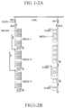
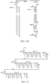
- Figs. 1-1 , 1-2A , 1-2B and 1-2C show a circuit of the full DC buck-boost power transmission system composed of a boost station and a buck station in different working states.
- the DC power supply charges the first battery pack unit, where each of the battery packs in the second battery pack unit is neither connected to the power grid nor to the load.
- a first part of the battery packs in the second battery pack unit is connected in series to form the series subunit to supply power to the load;
- a second part of the battery packs in the second battery pack unit is connected in parallel to be the parallel subunit to supply power to the load; and
- a third part of the battery packs in the second battery pack unit form the single battery pack unit to independently supply power to the load.
- the first battery pack unit is connected to the power grid through the high-voltage power grid to charge the second battery pack unit, and the second battery pack unit is connected to the power grid through the high-voltage cable to be charged.
- the first series stack in the first battery pack unit is divided into three first series sub-stacks, where each of the series sub-stack has the same number of battery packs, and the series sub-stacks are alternately connected to the high-voltage power grid to charge the second battery pack unit.
- the battery packs in the first battery pack unit are connected in parallel and charged by the DC power supply again.
- the second series stack in the second battery pack unit is separated into three power supplies, including a series subunit with a plurality of battery packs connected in series, a parallel subunit with a plurality of battery packs connected in parallel, and a single battery pack subunit.
- the series subunit, the parallel subunit and the single battery pack subunit are respectively connected to their load interfaces to supply power to their loads.
- boost substation In the full DC buck-boost transmission system, battery packs can be connected in series in remote locations to meet the voltage requirements and connected to the DC power grid to become a DC power source.
- several low-voltage boost stations can be connected in series to form a total high-voltage boost station.
- the former is called a boost substation and the latter is called a boost station.
- Each of the boost substations has its own primary power supply for charging. These primary power supplies can be in different locations, and they can also be power supplies of different nature.
- the number of battery packs in the boost station is determined by the grid voltage and the nominal voltage of the battery packs.
- Figs. 1-3 and 1-4 show a diagram of the structure and status of the boost station.
- the battery packs can be divided into A-type battery pack, B-type battery pack and C-type battery pack, in which: As shown in Fig. 1-5 , the A-type battery pack is an ordinary battery pack without any additional components or accessories. However, in actual appliances, a single-pole single-throw switch is provided at the positive electrode of the boost station, and a single-pole double-throw switch is provided at the negative electrode of the buck station.
- a diode is provided at a positive electrode of the ordinary battery pack to allow current to flow into the battery pack and prevent current from flowing out of the battery pack.
- There is a single-pole double-throw switch provided between the diode and the positive electrode. When the positive electrode of the battery pack is connected to the diode through the switch, the battery can be charged; when the switch is connected to the load, the battery packs supply power to the load.
- a single-pole single-throw switch is provided at the positive electrode of the buck station and a single-pole double-throw switch is provided at the negative electrode of the buck station.
- a diode is provided at a negative electrode of the ordinary battery pack to allow current to flow out of the battery pack and prevent current from flowing into the battery pack.
- There is a single-pole double-throw switch provided between the diode and the negative electrode. When the negative electrode of the battery pack is connected to the diode through the switch, the battery can be charged; when the switch is connected to the load, the battery packs supply power to the load.
- a single-pole double-throw switch is provided at the positive electrode of the buck station and a single-pole single-throw switch is provided at the negative electrode of the buck station.
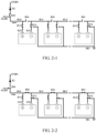
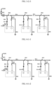
- FIG 2-1 shows a circuit in which the first battery pack unit in the boost station adopting the A-type battery packs is connected to the power grid through the high-voltage cable for power supplying; as shown in Fig. 2-2 , the states switches are changed, so that each of the battery packs in the first battery pack unit is connected in parallel, where the positive electrode of the battery packs is connected to the DC power supply, and the negative electrode of the battery packs is connected to the ground wire, so as to be charged from the first battery pack unit.
- the second battery pack unit in the buck station adopting the A-type battery packs forms subunits with three typical connection modes, including a single battery pack subunit, a parallel subunit (parallel combination of the battery packs) and a series subunit (battery packs connected in series), where the specific circuit diagram and implementation process are given as below.
- each of the A-type battery packs in the second battery pack unit is connected in series to form the second series stack for charging.
- the battery packs are connected to the high-voltage interface, and the diode is turned on, so that all the battery packs are charged, where the diode is provided for preventing the battery packs in the second battery pack from sending power to the high-voltage power grid.
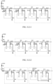
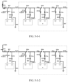
- FIG 3-2-1 shows a circuit according to an arrangement of the present disclosure, in which the second battery pack unit in the buck station adopting the A-type battery packs for charging on the buck side.
- Fig. 3-2-2 after the charging on the buck side is completed, a part of the battery packs in the second battery pack unit is connected in series to form a series subunit, where each of the battery packs is connected in series to become a series subunit.
- the second battery pack unit in the buck station adopting the B-type ordinary battery packs forms subunits with three typical connection modes, including a single battery pack subunit, a parallel subunit and a series subunit, where the specific circuit diagram and implementation process are given as below.
- the second battery pack unit in the buck station adopting the B-type battery pack is charging on the buck side.
- the switch 83 is connected to the high-voltage interface.
- each of the B-type battery packs can independently supply their own loads.
- the positive electrode of each of the battery packs is connected to the bypass cable, and the other end of each of the battery packs is connected to the ground wire, so that the battery packs are connected in parallel to supply power.
- the battery packs in the second battery pack unit are connected in series to form a series subunit to supply power to the loads.
- the second battery pack unit in the buck station adopting the C-type ordinary battery packs forms subunits with three typical connection modes, including a single battery pack subunit, a parallel subunit and a series subunit, where the specific circuit diagram and implementation process are given as below.
- each of the C-type battery packs can independently supply their own loads.
- the second series stack formed by the C-type battery packs in the second battery pack unit is charging on the buck side, where a bypass cable is provided at the negative electrode of each of the battery packs.
- the battery packs in the second battery pack unit are connected in series to form a series subunit to supply power to the loads.
- the battery packs in the second battery pack unit can be moved away from the installation positions to supply power to the loads, or supply power to the loads without being moved away from the installation positions.
- the full DC buck-boost power transmission system As shown in Figs. 7-1 and 7-2 , the full DC buck-boost power transmission system provided in the present disclosure is actually an open full DC buck-boost power station and transmission grid, which has the following characteristics.
- the boost station In order to ensure that the DC power supply on the primary side continuously supplies power to the open full DC high voltage transmission and distribution power grid, the boost station should provide with two or more sets of the first battery pack unit for receiving the power input from the DC power supply on the primary side in turn. Similarly, in order to ensure that the buck station continuously supplies power to the loads, two or more sets of the second battery pack units should be provided.
- the battery packs are adopted as the main component and the conversion of the connection mode is applied, so that the battery packs form a parallel connection for low-voltage charging, and then the battery packs are changed to be connected in series to obtain a high-voltage power to supply power to the second battery pack unit.
- the second battery pack unit is divided into a plurality of single battery pack subunits, a plurality of parallel subunits and a plurality of series subunits to supply power to their corresponding loads.
- the connection modes of the first and the second battery pack units are respectively restored, and then the system is performed repeatedly in the above-mentioned way, thereby achieving storage, boost, power transmission, buck and supply of the DC power. Since there is no AC-DC conversion in the process, the system provided in the present disclosure is called the full DC buck-boost transmission system.
- the full DC high voltage transmission and distribution power grid provided in the present disclosure has the following basic working principles:
- each of the battery packs of the first battery pack unit in the boost station has the same specification, that is, each of the battery packs has the same nominal voltage, the same rated capacity and the same optimal charging current.
- a matching relationship between a nominal voltage V b and the actual voltage V c is: V b ⁇ V c / 1.2 ;
- the optimal charging current of each of the battery packs is I b ; the number of the battery packs in the first battery pack is n; I b and I c should preferably satisfy the following relationship: I c ⁇ nI b
- the transmission condition should satisfy the following relationship: V w ⁇ nV b ; then n ⁇ V w / V b .
- the series subunits with higher voltage should be placed at a high-voltage terminal closer to the power grid.
- the DC power supply on the primary side adopts an isolated photovoltaic power plant, where the isolated photovoltaic power plant has a power of 2.4 MW, an output voltage of 480 V, and an output current of 5000 A.
- each of the A-type battery packs in the first battery pack unit is connected in parallel, so that the DC power supply on the primary side charges the first battery pack unit at full capacity.
- all battery packs in the second battery pack unit share the same specification, which can be any one of A-type battery packs, B-type battery packs, and C-type battery packs.
- the connection mode of each of the battery packs in the second battery pack unit is changed according to the user loads and the type of the battery pack.
- the second battery pack unit can be configured as follows.
- the DC power supply on the primary side adopts an isolated photovoltaic power plant, where the isolated photovoltaic power plant has a power of 48 MW, an output voltage of 480 V, and an output current of 10000 A.
- buck stations 140 there are four buck stations 140, including a buck station 140a, a buck station 140b, a buck station 140c and a buck station 140d, where the composition of the four buck stations is as follows.
- all battery packs in the second battery pack unit share the same specification, which can be any one of A-type battery packs, B-type battery packs, and C-type battery packs.
- the connection mode of each of the battery packs in the second battery pack unit is changed according to the user loads and the type of the battery pack.
- the second battery pack unit a can be configured as follows.
- all battery packs in the second battery pack unit share the same specification, which can be any one of A-type battery packs, B-type battery packs, and C-type battery packs.
- the connection mode of each of the battery packs in the second battery pack unit is changed according to the user loads and the type of the battery pack.
- the second battery pack unit a can be configured as follows.
- the second battery pack unit b is divided into two types of subunits, where the battery packs in each type of subunits can be any one of A-type battery packs, B-type battery packs, and C-type battery packs.
- the connection mode of each of the battery packs in the second battery pack unit is changed according to the user loads and the connection mode of the buck station a.
- the second battery pack unit can be configured as follows.
- the first specification subunit can be configured as follows.
- all battery packs in the second battery pack unit share the same specification, which can be any one of A-type battery packs, B-type battery packs, and C-type battery packs.
- the second battery pack unit are connected according to user loads, so that each of the battery packs is used as a charging pile for nearby electric vehicles.
- the DC power supply on the primary side includes a first DC power supply 110a, a second DC power supply 11b and a third DC power supply 110c, where the first DC power supply 110a is a photovoltaic power station, which has a power of 2.4 MW, an output voltage of 480 V, and an output current of 5000 A; the second DC power supply 110b is a photovoltaic power station, which has a power of 4.8 MW, an output voltage of 480 V, and an output current of 10000 A; and the third DC power supply 110 is a DC power supply rectified from a hydropower station or a DC power station, which has a power of 6 MW, an output voltage of 480 V, and an output current of 12500 A.
- the first DC power supply 110a is a photovoltaic power station, which has a power of 2.4 MW, an output voltage of 480 V, and an output current of 5000 A
- the second DC power supply 110b is a photovoltaic power station, which has a power of
- the battery packs in the first battery pack unit are A-type battery packs with the same specification, where the nominal voltage of each of the battery packs is 400 V, the optimal charging current of each of the battery packs is 250 A.
- the boost substation matched with the DC power supply a has 20 battery packs; the boost substation matched with the DC power supply b has 40 battery packs; and the boost substation matched with the DC power supply c has 50 battery packs.
- the battery packs in each of the boost substations are changed to be connected in series, and the voltage of each of boost substation is 8 kV, 16 kV and 20 kV, respectively.
- each of the boost substation is connected in series at different places, and is connected to the power grid through the diode for power transmission, where the total voltage is 44 KV, and the transmission current is 250A.
- buck stations There are three buck stations, including a first buck substation 140-1, a second buck substation 140-2 and a third buck substation 140-3, where their compositions are as follows.
- the connection mode of each of the battery packs in the first buck substation 140-1 is changed according to the user loads and the type of the battery pack.
- the first buck substation 142-1 can be configured as follows.
- all battery packs in the second battery pack unit share the same specification, which can be any one of A-type battery packs, B-type battery packs, and C-type battery packs.
- all battery packs in the second battery pack unit share the same specification, which can be any one of A-type battery packs, B-type battery packs, and C-type battery packs.
- each of the single battery pack subunits is 0.3kV, and each of the single battery pack subunits is used as a charging pile for nearby electric vehicles.
- the full DC buck-boost power transmission system is the same as that in the above-mentioned arrangements, and the DC power supply on the primary side includes a first DC power supply 110-1A, a second DC power supply 110-1B, a third DC power supply 110-1C and a fourth DC power supply 110-1D, where the first DC power supply 110-1A is a photovoltaic power station, which has a power of 24 MW, an output voltage of 480 V, and an output current of 50000 A; the second DC power supply 110-1B is a photovoltaic power station, which has a power of 48 MW, an output voltage of 480 V, and an output current of 100000 A; the third DC power supply 110-1C is a DC power supply rectified from a hydropower station or a DC power station, which has a power of 23 MW, an output voltage of 6300 V, and an output current of 3650 A; and the fourth DC power supply 110-1D is a photovoltaic power station, which has a power of 80
- the first boost station 121-1 has three boost substations at different places connected in series, including a first boost substation 121-1A, a second boost substation 121-1B, and a third boost substation 121-1C.
- the battery packs in the first boost substation and the second boost substation are A-type battery packs with the same specification, where the nominal voltage of each of the battery packs is 400 V, the optimal charging current of each of the battery packs is 400 A.
- the first boost substation 121-1A matched with the first DC power supply 110-1A has 124 battery packs; and the second boost substation 121-1B matched with the second DC power supply 110-1B has 250 battery packs.
- Each of the boost substations is connected in series at different places, and is connected to the power grid through the diode for power transmission, the total voltage is 196.85 kV, and the current is 400 A.
- the battery packs in the second boost station 121-2 are A-type battery pack with the same specification, where the nominal voltage of each of the battery packs is 400 V, and the optimal charging current of each of the battery packs is 339 A.
- the second boost substation 121-1A matched with the fourth DC power supply 110-2 has 492 battery packs.
- buck stations There are four buck stations, including a first buck substation 140-1, a second buck substation 140-2, a third buck substation 140-3, where their compositions are as follows.
- all battery packs in the second battery pack unit share the same specification, which can be any one of A-type battery packs, B-type battery packs, and C-type battery packs.
- the connection mode of each of the battery packs in the second battery pack unit is changed according to the user loads and the type of the battery pack.
- the second battery pack unit can be configured as follows.
- all battery packs in the second battery pack unit share the same specification, which can be any one of A-type battery packs, B-type battery packs, and C-type battery packs.
- the connection mode of each of the battery packs in the second battery pack unit is changed according to the user loads and the type of the battery pack.
- the second battery pack unit can be configured as follows.
- all battery packs in the second battery pack unit share the same specification, which can be any one of A-type battery packs, B-type battery packs, and C-type battery packs.
- the connection mode of each of the battery packs in the second battery pack unit is changed according to the user loads and the type of the battery pack.
- the second battery pack unit can be configured as follows.
- all battery packs in the second battery pack unit share the same specification, which can be any one of A-type battery packs, B-type battery packs, and C-type battery packs.
- the connection mode of each of the battery packs in the second battery pack unit is changed according to the user loads and the type of the battery pack.
- the second battery pack unit can be configured as follows.
- the full DC buck-boost power transmission system is the same as that in the above-mentioned arrangements, and the DC power supply on the primary side is a photovoltaic power station, which has a power of 14.4 MW, an output voltage of 480 V, and an output current of 30000 A.
- the high voltage boost substation 120A adopts the A-type battery packs, where the nominal voltage of each of the battery packs is 400 V; the optimal charging current of each of the battery packs is 200A; and the number of the battery packs is 150.
- the high current boost substation 120B adopts the A-type battery packs, where the nominal voltage of each of the battery packs is 400 V; the optimal charging current of each of the battery packs is 600 A; and the number of the battery packs is 50. If the sum of the optimal charging current after the two boost stations are connected in parallel is equal to 30000 A, the power supplies on the primary side can respectively charge the battery packs at full capacity.
- all battery packs in the second battery pack unit share the same specification, which can be any one of A-type battery packs, B-type battery packs, and C-type battery packs.
- the nominal voltage of each of the battery packs is 120 V; the optimal charging current each of the battery packs is 198 A, which is slightly less than the current delivered by the high voltage boost station, and slightly less than one-third of the current delivered by the high current boost station.
- the above-mentioned full DC buck-boost power transmission system is applied to an isolated photovoltaic power station to continuously supply power to electrical loads.
- the two boost stations 120A and 120B are equivalent for the same buck station.
- the DC power supply on the primary side is a photovoltaic power station or a wind turbine generator.
- the DC power supply When the DC power supply is a photovoltaic power station, the DC power supply has a power of 2.4 MW, an output voltage of 960 V, and an output current of 2500 A.
- the battery packs in the second battery pack unit can be any one of A-type battery packs, B-type battery packs, and C-type battery packs.
- the nominal voltage of each of the battery packs is 120 V.
- the battery packs in the second battery pack unit are constructed according to the optimal charging current as follows.
- the DC power supply When the DC power supply is a wind turbine generator with a DC output without inverter, the DC power supply has a power of 1 MW, an output voltage of 480 V, and an output current of 2083 A.
- the battery packs in the second battery pack unit can be any one of A-type battery packs, B-type battery packs, and C-type battery packs.
- the nominal voltage of each of the battery packs is 100 V.
- the battery packs in the second battery pack unit are constructed according to the optimal charging current as follows.
- the nominal voltage of each of the series subunits is 400 V, and all the series subunits are connected in parallel for charging.
- GYDW is a high-voltage power grid, where there are three boost stations and two buck stations connected to the high-voltage power grid.
- CDCLD1 is composed of A-type ordinary type battery packs, where the fully charged battery packs in the drawing are filled with gray to distinguish; the CDCLD1 is connected to the high-voltage power grid through the diode to supply power.
- ZLJK1 is a DC interface 1 provided for the first series stack 122-1.
- CDCLD2 is composed of the A-type battery pack, where the fully charged battery packs in the drawing are filled with gray to distinguish; the CDCLD2 is connected to the high-voltage power grid through the diode to supply power; the second series stack 2 in the first battery pack unit is composed of a plurality of series sub-stacks, including CDCLD2a, CDCLD2b, and CDCLD2c, where the series sub-stacks may not be arranged in the same place, and there is a certain distance from each other.
- ZLJK2a is a DC interface 2a provided for the CDCLD2a
- ZLJK2b is a DC interface 2b provided for the CDCLD2b
- ZLJK2c is a DC interface 2c, provided for the CDCLD2c.
- CDCLD3 is composed of A-type battery packs, where the fully charged battery packs in the drawing are filled with gray to distinguish; the CDCLD2 is connected to the high-voltage power grid through the diode to supply power.
- ZLJK3 is a DC interface 3, provided for the third series stack 3 in the first battery pack unit.
- the diode is provided for preventing current flowing into the charging series stacks.
- BCDXDCZ1 is a first series stack 1 to be charged, consisting of B-type or C-type battery packs. The battery packs without fill color in the drawing are being charged. After the BCDXDCZ1 is fully charged, the connection mode of the battery packs can be changed to form a single battery pack subunit, a parallel subunit and a series subunit.
- FZJK1a, FZJK1b and FZJK1c are respectively a load interface provided for the parallel combination of the battery packs to be charged or the series stack of the battery packs to be charged.
- BCDXDCZ2 is a second series stack 2 to be charged, consisting of B-type or C-type battery packs. The battery packs without fill color in the drawing are being charged.
- FZJK1a, FZJK1b and FZJK1c are respectively a load interface provided for the parallel combination of the battery packs to be charged or the series stack of the battery packs to be charged.
- YLJK a reserved interface, configured to connect the other subunit of the second battery group unit that meets the technical indicators in the future to the power grid. Therefore, an open power grid is provided for connecting to other power grids in remote regions.
- FIG 7-2 schematically show the circuit of the full DC high voltage transmission and distribution power grid in another working state according to the arrangement of the present disclosure.
- the third series stack 3 is disconnected from the high-voltage power grid and connected to the ZLJK3 for charging on the boost side.
- the second series stack to be charged 2 forms a parallel subunit and a series subunit, so that the subunits are connected to their corresponding loads to supply power;
- FZJK2a a load interface 2a, connected to the series subunit;
- FZJK2b a load interface 2b, connected to the parallel subunit;
- FZJK2c a load interface 2c, connected to the single battery pack subunit.
- Each of the charging series stacks in the first battery pack unit and each of the series stacks to be charged the second battery pack unit have two working states of being charged and charging, but the periods of their working state are different. Therefore, there are many combinations of working conditions of the entire power grid, and the combinations of working conditions are constantly changing. There are about dozens of connection modes, where only two connection modes are listed out in the above-mentioned arrangements. In actual use, the switching of the working conditions of each of the boost stations and each of the buck station should be controlled by a power grid management center.
- the smart grid technologies including hardware and software for overall management, control, adjustment, and detection are not elaborated herein.
- the power grid is provided with the following characteristics: a battery pack in the first battery pack unit for boosting is disconnected from the power grid when charging on the boost side, and they are connected to the power grid only when they charge the battery packs in the second battery pack unit on the buck side.
- the battery packs in the second battery pack unit for bucking is connected to the power grid only when they need to be charged, and they are disconnected from the power grid when supplying power to the loads. Therefore, if the power grid fails, the power station can continue to work, where the battery packs in the first battery pack unit can continue to be charged, and the battery packs in the second battery pack unit can continue to supply power to the loads. Therefore, the DC power supply system has the advantages of safe, easy to handle power grid accidents, and simple and reliable control and management system.
- the present disclosure tightly combines power generation, energy storage and power supply, and has strong resistance to fluctuations in the power generation terminal and the user terminal.
- the present disclosure can obtain high-quality DC power and eliminate various types of AC harmonics.
- the present disclosure relies on the conversion between electrical energy and chemical energy.
- the full DC buck-boost power transmission system is more energy-saving if high quality and high energy storage density are adopted.
- AC power generation occupies a great advantage in the global power supply.
- the development of the technologies such as detection, control, management, maintenance and overhaul will be promoted, which in turn provides mature technologies and experience for the establishment of cross-regional and even global DC power grid.
Landscapes
- Engineering & Computer Science (AREA)
- Power Engineering (AREA)
- Charge And Discharge Circuits For Batteries Or The Like (AREA)
- Supply And Distribution Of Alternating Current (AREA)
Claims (4)
- Vollständiges DC-Boost-Buck-Stromübertragungssystem, umfassend:mindestens eine Boost-Station;mindestens eine Buck-Station;ein Stromnetz-Managementzentrum;eine Gleichstromversorgung; undein Kabel (130), das zur Verbindung der mindestens einen Boost-Station mit der mindestens einen Buck-Station vorgesehen ist;dadurch gekennzeichnet, dass die mindestens eine Boost-Station eine Vielzahl von ersten Batteriepaketen umfasst und die ersten Batteriepakete zur Speicherung von Gleichstrom aus der Gleichstromversorgung parallel geschaltet sind;wobei, wenn die Speicherung der ersten Batteriepakete abgeschlossen ist, die ersten Batteriepakete von der Gleichstromversorgung getrennt und seriell geschaltet werden, um den Boost-Vorgang durchzuführen, und dann mit dem Kabel (130) verbunden sind, um die Gleichstrom an die mindestens eine Buck-Station zu liefern; und wobei, nachdem die Übertragung der Gleichstrom abgeschlossen ist, die ersten Batteriepakete von dem Kabel (130) getrennt und parallelgeschaltet werden und dann mit der Gleichstromversorgung zur Speicherung der Gleichstrom verbunden sind;wobei die mindestens eine Buck-Station eine Vielzahl von zweiten Batteriepaketen umfasst und die zweiten Batteriepakete zur Übertragung von Gleichstrom von der Boost-Station zur Buck-Station seriell geschaltet sind;wobei, wenn die Übertragung des Gleichstroms abgeschlossen ist, die zweiten Batteriepakete der mindestens einen Buck-Station so konfiguriert sind, dass sie eine Vielzahl von Einzelbatteriepaket-Untereinheiten, eine Vielzahl von Reihenuntereinheiten und eine Vielzahl von Paralleluntereinheiten bilden, so dass die verschiedenen Arten von Untereinheiten unabhängig voneinander an ihre entsprechenden Lasten angeschlossen werden, um den Gleichstrom von den Untereinheiten an ihre entsprechenden Lasten zu übertragen; wobei, nachdem die Zufuhr von Gleichstrom von den Untereinheiten zu ihren entsprechenden Lasten abgeschlossen ist, die zweiten Batteriepakete in der mindestens einen Boost-Station von den Lasten getrennt und seriell geschaltet werden und dann mit dem Kabel (130) zur Übertragung von Gleichstrom von der Boost-Station verbunden sind; undwobei das Stromnetz-Managementzentrum so konfiguriert ist, dass es die Verbindungsmodi der Batteriepakete (XDCZ00) in der mindestens einen Boost-Station und der mindestens einen Buck-Station zwischen Reihenschaltung und Parallelschaltung umschaltet und die Verbindung und Trennung der mindestens einen Boost-Station mit dem Kabel (130) sowie die Verbindung und Trennung der mindestens einen Buck-Station mit dem Kabel (130) umschaltet, um die Speicherung, den Boost, die Übertragung, den Buck und die Versorgung mit Gleichstrom zu erreichen.
- Vollständiges DC-Boost-Buck-Stromübertragungssystem nach Anspruch 1, wobei, nachdem die Übertragung der Gleichstrom abgeschlossen ist, die Reihenuntereinheiten in der mindestens einen Buck-Station als Gleichstromversorgung konfiguriert sind, um ein Stromnetz mit einer Spannung zu versorgen, die niedriger als die Spannung der Reihenuntereinheiten in der mindestens einen Buck-Station ist.
- Vollständiges DC-Boost-Buck-Stromübertragungssystem nach Anspruch 1, wobei die mindestens eine Boost-Station mehrere seriell geschaltete Boost-Unterstationen umfasst; die mehreren Boost-Unterstationen jeweils an verschiedenen Orten installiert sind; wobei die Gleichstromversorgung aus mehreren Gleichstromversorgungen besteht, die sich im Typ voneinander unterscheiden und zum Laden der ersten Batteriepakete jeder der Boost-Unterstationen konfiguriert sind.
- Vollständiges DC-Boost-Buck-Stromübertragungssystem nach Anspruch 1, wobei die Boost-Station angrenzend an die Gleichstromversorgung angeordnet ist und in der Lage ist, Spannung auszugeben; die Buck-Station zentral einer Benutzergruppe eingerichtet ist und in der Lage ist, eine Zugangsspannung bereitzustellen; und eine Vielzahl von Reservestromversorgungseingängen und eine Vielzahl von Stromversorgungsausgängen weiterhin für den Zugang zu Boost-Stationen und Buck-Stationen vorgesehen sind.
Applications Claiming Priority (2)
| Application Number | Priority Date | Filing Date | Title |
|---|---|---|---|
| CN201711471724.4A CN109995011B (zh) | 2017-12-29 | 2017-12-29 | 全直流升降压输送电系统及方法 |
| PCT/CN2018/000407 WO2019127617A1 (zh) | 2017-12-29 | 2018-12-05 | 全直流升降压输送电系统及方法 |
Publications (4)
| Publication Number | Publication Date |
|---|---|
| EP3734794A1 EP3734794A1 (de) | 2020-11-04 |
| EP3734794A4 EP3734794A4 (de) | 2021-11-03 |
| EP3734794C0 EP3734794C0 (de) | 2025-06-25 |
| EP3734794B1 true EP3734794B1 (de) | 2025-06-25 |
Family
ID=67062917
Family Applications (1)
| Application Number | Title | Priority Date | Filing Date |
|---|---|---|---|
| EP18895508.2A Active EP3734794B1 (de) | 2017-12-29 | 2018-12-05 | Gleichstrom-auf-/abwärtsenergieübertragungssystem |
Country Status (4)
| Country | Link |
|---|---|
| US (1) | US11362525B2 (de) |
| EP (1) | EP3734794B1 (de) |
| CN (1) | CN109995011B (de) |
| WO (1) | WO2019127617A1 (de) |
Families Citing this family (26)
| Publication number | Priority date | Publication date | Assignee | Title |
|---|---|---|---|---|
| CN109995011B (zh) * | 2017-12-29 | 2024-04-16 | 冯良桓 | 全直流升降压输送电系统及方法 |
| US11289974B2 (en) | 2019-06-07 | 2022-03-29 | Anthony Macaluso | Power generation from vehicle wheel rotation |
| US11222750B1 (en) | 2021-03-22 | 2022-01-11 | Anthony Macaluso | Hypercapacitor apparatus for storing and providing energy |
| US11615923B2 (en) | 2019-06-07 | 2023-03-28 | Anthony Macaluso | Methods, systems and apparatus for powering a vehicle |
| US11685276B2 (en) | 2019-06-07 | 2023-06-27 | Anthony Macaluso | Methods and apparatus for powering a vehicle |
| US11641572B2 (en) | 2019-06-07 | 2023-05-02 | Anthony Macaluso | Systems and methods for managing a vehicle's energy via a wireless network |
| CN114375276B (zh) * | 2019-10-09 | 2024-12-24 | 小鹰公司 | 具有前掠翼的短距起降载具 |
| CN110829519B (zh) * | 2019-10-22 | 2024-05-14 | 江苏大学 | 一种基于可拆分式蓄电池组的多输入储能系统及其控制方法 |
| CN110943455B (zh) * | 2020-01-14 | 2025-04-22 | 浙江大学建筑设计研究院有限公司 | 一种多地启停控制装置及其设计方法 |
| CN112937337B (zh) * | 2021-01-21 | 2025-05-13 | 华为数字能源技术有限公司 | 一种充电系统及电动汽车 |
| EP4106127B1 (de) * | 2021-06-14 | 2024-05-15 | Aptiv Technologies AG | Elektrische architektur |
| CN113765177B (zh) * | 2021-07-30 | 2024-06-11 | 华为数字能源技术有限公司 | 一种电池模块和充电系统 |
| EP4385809A4 (de) * | 2021-09-22 | 2025-01-22 | Huawei Digital Power Technologies Co., Ltd. | Ladesystem |
| CN114300764B (zh) * | 2021-12-22 | 2024-02-20 | 东莞新能安科技有限公司 | 电池模组和储能系统 |
| US11472306B1 (en) | 2022-03-09 | 2022-10-18 | Anthony Macaluso | Electric vehicle charging station |
| US11577606B1 (en) | 2022-03-09 | 2023-02-14 | Anthony Macaluso | Flexible arm generator |
| US20230324936A1 (en) * | 2022-04-12 | 2023-10-12 | Schweitzer Engineering Laboratories, Inc. | Direct current monitoring using a centralized protection and control system |
| CN114619909B (zh) * | 2022-04-22 | 2023-06-02 | 广东汇天航空航天科技有限公司 | 充电控制方法、装置、充电系统及电动飞行器的充电设备 |
| EP4270706A1 (de) | 2022-04-26 | 2023-11-01 | General Electric Technology GmbH | Gleichstromenergiespeichersystem |
| EP4270705A1 (de) | 2022-04-26 | 2023-11-01 | General Electric Technology GmbH | Gleichstromenergiespeichersystem |
| US11655024B1 (en) | 2022-05-25 | 2023-05-23 | Kitty Hawk Corporation | Battery systems with power optimized energy source and energy storage optimized source |
| CN114825909B (zh) * | 2022-06-01 | 2026-03-27 | 广州小鹏汽车科技有限公司 | 电池包的配电结构、电池包及车辆 |
| CN115733237B (zh) * | 2022-11-23 | 2025-11-18 | 华为数字能源技术有限公司 | 储能系统和黑启动装置 |
| US12160132B2 (en) * | 2023-01-30 | 2024-12-03 | Anthony Macaluso | Matable energy storage devices |
| US12407219B2 (en) | 2023-02-28 | 2025-09-02 | Anthony Macaluso | Vehicle energy generation system |
| US12412430B2 (en) | 2023-12-22 | 2025-09-09 | Anthony Macaluso | Systems and methods for managing a vehicle's energy via a wireless network |
Family Cites Families (34)
| Publication number | Priority date | Publication date | Assignee | Title |
|---|---|---|---|---|
| GB190722581A (en) * | 1907-10-14 | 1909-01-14 | Alfred Mills Taylor | Improvements in Electric Battery Substations Fed from Alternating Current Systems. |
| US4274043A (en) * | 1978-12-21 | 1981-06-16 | The Dow Chemical Company | Efficient, high power battery module; D.C. transformers and multi-terminal D.C. power networks utilizing same |
| CN1016919B (zh) * | 1990-05-26 | 1992-06-03 | 季长青 | 开关电容隔离式直流变换器 |
| JP2000156934A (ja) * | 1998-11-19 | 2000-06-06 | Nissin Electric Co Ltd | 電力貯蔵システム及びその充電方法 |
| US6583522B1 (en) * | 2000-09-27 | 2003-06-24 | Worldwater Corp. | Switchable multiple source power supply |
| JP2010521720A (ja) * | 2006-12-06 | 2010-06-24 | ソーラーエッジ テクノロジーズ | Dc電源を用いた分散型電力ハーベストシステム |
| JP4894656B2 (ja) * | 2007-07-13 | 2012-03-14 | トヨタ自動車株式会社 | 車両 |
| CN201160230Y (zh) * | 2008-01-10 | 2008-12-03 | 周雨方 | 蓄电池充电装置 |
| JP4764499B2 (ja) * | 2009-08-05 | 2011-09-07 | 本田技研工業株式会社 | Dc/dcコンバータ及びそのdc/dcコンバータを備えた電力供給システム |
| US20130015805A1 (en) * | 2010-06-04 | 2013-01-17 | Triune Ip Llc | Energy storage element link and monitor |
| US8917075B2 (en) * | 2010-11-01 | 2014-12-23 | Anadigics, Inc. | Switched inductor DC-DC converter |
| JP5817103B2 (ja) * | 2010-11-12 | 2015-11-18 | ソニー株式会社 | 直並列切替システム、電力供給装置、電力供給制御装置及び直並列切替方法 |
| CN102931679A (zh) * | 2012-10-12 | 2013-02-13 | 吴加林 | 多级升压大功率光伏并网电站 |
| US20140300311A1 (en) * | 2013-04-08 | 2014-10-09 | Magnadyne Corporation | Portable power bank and battery booster |
| US9798367B2 (en) * | 2013-04-09 | 2017-10-24 | Intel Corporation | Controlling supply of power to computing devices with dynamically variable energy capacity |
| CN103368200A (zh) * | 2013-06-25 | 2013-10-23 | 南车株洲电力机车研究所有限公司 | 一种单端vsc—hvdc光伏发电系统 |
| US9148071B2 (en) * | 2013-07-29 | 2015-09-29 | Rhombus Energy Solutions, Inc. | DC source-to-AC grid tie-in power enhancement using multilevel inverter topology and resonant matrix tank converter |
| CN204030619U (zh) * | 2014-05-30 | 2014-12-17 | 贵州电力试验研究院 | 一种轻型直流输电设备高压直流侧电容充电结构 |
| CN205565845U (zh) * | 2014-07-02 | 2016-09-07 | Abb技术有限公司 | 用于给至少一个电动汽车的电池充电的系统 |
| US20160241026A1 (en) * | 2015-02-15 | 2016-08-18 | Skyworks Solutions, Inc. | Reconfigurable power supply cell for efficient boost and buck-boost applications |
| CN107294129A (zh) * | 2017-06-22 | 2017-10-24 | 胡炎申 | 电池逆变串联系统及逆变电源装置 |
| DE102017210611B4 (de) * | 2017-06-23 | 2022-05-05 | Audi Ag | Elektrische Energieliefervorrichtung mit einer Stromschienenmatrix sowie Verfahren zum Betreiben der Energieliefervorrichtung |
| DE102017210610A1 (de) * | 2017-06-23 | 2018-12-27 | Audi Ag | Elektrische Energieliefervorrichtung mit einer Vielzahl von austauschbaren Nutzeinheiten sowie Verfahren zum Betreiben einer solchen Energieliefervorrichtung |
| US10673340B2 (en) * | 2017-11-16 | 2020-06-02 | Abb Schweiz Ag | Isolated boost-buck power converter |
| CN109995011B (zh) * | 2017-12-29 | 2024-04-16 | 冯良桓 | 全直流升降压输送电系统及方法 |
| DE102018106305B4 (de) * | 2018-03-19 | 2020-06-25 | Dr. Ing. H.C. F. Porsche Aktiengesellschaft | Wechselstromladung einer intelligenten Batterie |
| DE102018116480A1 (de) * | 2018-07-06 | 2020-01-09 | Ostbayerische Technische Hochschule Regensburg | Batterieschaltung mit Multiplexer-Batteriemodulen |
| CN111211688A (zh) * | 2018-11-21 | 2020-05-29 | 伊顿智能动力有限公司 | Dc-dc变换器和双向dc-dc变换器及包括其的不间断电源 |
| AU2019438860A1 (en) * | 2019-04-04 | 2021-11-04 | General Electric Company | Systems and methods for modular power conversion units in power supply systems |
| DE102020104252A1 (de) * | 2019-05-21 | 2020-11-26 | Vacon Oy | Leistungswandler |
| US20210006076A1 (en) * | 2019-06-14 | 2021-01-07 | X-wave Innovations, Inc. | Reconfigurable Energy Storage Module and Optimum Power Transfer Algorithm for Distributed and Modular Energy Storage Systems |
| EP3772152B1 (de) * | 2019-08-02 | 2023-10-04 | ABB E-mobility B.V. | Batterieladegerätevorrichtung und zugehöriges lastverlustschutzverfahren |
| US20210126471A1 (en) * | 2019-10-28 | 2021-04-29 | Modulaire Power System Private Limited | System and method for managing charge control of a battery array |
| US12027890B2 (en) * | 2020-04-02 | 2024-07-02 | Qualcomm Incorporated | Modulating supply voltage generated by voltage regulator for transmission of data and power |
-
2017
- 2017-12-29 CN CN201711471724.4A patent/CN109995011B/zh active Active
-
2018
- 2018-12-05 WO PCT/CN2018/000407 patent/WO2019127617A1/zh not_active Ceased
- 2018-12-05 EP EP18895508.2A patent/EP3734794B1/de active Active
-
2020
- 2020-06-29 US US16/914,929 patent/US11362525B2/en active Active
Also Published As
| Publication number | Publication date |
|---|---|
| US20200381927A1 (en) | 2020-12-03 |
| US11362525B2 (en) | 2022-06-14 |
| WO2019127617A1 (zh) | 2019-07-04 |
| EP3734794C0 (de) | 2025-06-25 |
| EP3734794A1 (de) | 2020-11-04 |
| CN109995011A (zh) | 2019-07-09 |
| EP3734794A4 (de) | 2021-11-03 |
| CN109995011B (zh) | 2024-04-16 |
Similar Documents
| Publication | Publication Date | Title |
|---|---|---|
| EP3734794B1 (de) | Gleichstrom-auf-/abwärtsenergieübertragungssystem | |
| US9048694B2 (en) | DC connection scheme for windfarm with internal MVDC collection grid | |
| EP4187746A1 (de) | Wind-solar-gleichstromkombinationssystem | |
| EP2815913A1 (de) | Ladeanordnung für elektrische Fahrzeuge | |
| EP3985821A1 (de) | Stromnetz | |
| EP3985823A1 (de) | Stromnetz | |
| US10547173B2 (en) | Power generation system | |
| GB2177556A (en) | Dc-ac-dc power supply | |
| US12255461B2 (en) | Charging station with high frequency distribution network | |
| CN107431357A (zh) | 混合高压直流换流站及其操作方法 | |
| JP6454540B2 (ja) | 電力変換装置 | |
| US20220166219A1 (en) | Systems and methods for modular power conversion units in power supply systems | |
| JP2016201893A (ja) | 系統連系システム | |
| CN205565845U (zh) | 用于给至少一个电动汽车的电池充电的系统 | |
| WO2018070037A1 (ja) | 電力変換システム、電力供給システムおよび電力変換装置 | |
| Razzaghzadeh et al. | Analysis of a bidirectional DC-DC converter with high voltage gain | |
| CN104852444A (zh) | 一种应用于电动汽车的直流充电装置 | |
| EP4270748A1 (de) | Wechselrichter mit skalierbarem gleichspannungshochsetzsteller | |
| CN111987919B (zh) | 电力转换器 | |
| Rawat et al. | Standalone Solar PV Plant for Distributed Battery Charging Using PSFB and DAB | |
| CN106564397A (zh) | 直流充电的充电站系统 | |
| RU2321149C1 (ru) | Преобразователь переменного напряжения в постоянное с 24-кратной частотой пульсации | |
| KR102098020B1 (ko) | 커패시터 커플링 구조를 갖는 직류 전압 제어 장치 | |
| Hayashi et al. | Multi-cell rectifier using GaN-FET for highly efficient next generation 380-V dc distribution system | |
| RU123593U1 (ru) | Система передачи электроэнергии постоянным током высокого напряжения |
Legal Events
| Date | Code | Title | Description |
|---|---|---|---|
| STAA | Information on the status of an ep patent application or granted ep patent |
Free format text: STATUS: THE INTERNATIONAL PUBLICATION HAS BEEN MADE |
|
| PUAI | Public reference made under article 153(3) epc to a published international application that has entered the european phase |
Free format text: ORIGINAL CODE: 0009012 |
|
| STAA | Information on the status of an ep patent application or granted ep patent |
Free format text: STATUS: REQUEST FOR EXAMINATION WAS MADE |
|
| 17P | Request for examination filed |
Effective date: 20200729 |
|
| AK | Designated contracting states |
Kind code of ref document: A1 Designated state(s): AL AT BE BG CH CY CZ DE DK EE ES FI FR GB GR HR HU IE IS IT LI LT LU LV MC MK MT NL NO PL PT RO RS SE SI SK SM TR |
|
| AX | Request for extension of the european patent |
Extension state: BA ME |
|
| DAV | Request for validation of the european patent (deleted) | ||
| DAX | Request for extension of the european patent (deleted) | ||
| REG | Reference to a national code |
Ref country code: DE Ref legal event code: R079 Ipc: H02J0007000000 Ref country code: DE Ref legal event code: R079 Ref document number: 602018083031 Country of ref document: DE Free format text: PREVIOUS MAIN CLASS: H02J0007020000 Ipc: H02J0007000000 |
|
| A4 | Supplementary search report drawn up and despatched |
Effective date: 20211005 |
|
| RIC1 | Information provided on ipc code assigned before grant |
Ipc: H02J 1/10 20060101ALI20210929BHEP Ipc: H02J 7/00 20060101AFI20210929BHEP |
|
| STAA | Information on the status of an ep patent application or granted ep patent |
Free format text: STATUS: EXAMINATION IS IN PROGRESS |
|
| 17Q | First examination report despatched |
Effective date: 20230801 |
|
| GRAP | Despatch of communication of intention to grant a patent |
Free format text: ORIGINAL CODE: EPIDOSNIGR1 |
|
| STAA | Information on the status of an ep patent application or granted ep patent |
Free format text: STATUS: GRANT OF PATENT IS INTENDED |
|
| INTG | Intention to grant announced |
Effective date: 20250129 |
|
| GRAS | Grant fee paid |
Free format text: ORIGINAL CODE: EPIDOSNIGR3 |
|
| GRAA | (expected) grant |
Free format text: ORIGINAL CODE: 0009210 |
|
| STAA | Information on the status of an ep patent application or granted ep patent |
Free format text: STATUS: THE PATENT HAS BEEN GRANTED |
|
| AK | Designated contracting states |
Kind code of ref document: B1 Designated state(s): AL AT BE BG CH CY CZ DE DK EE ES FI FR GB GR HR HU IE IS IT LI LT LU LV MC MK MT NL NO PL PT RO RS SE SI SK SM TR |
|
| REG | Reference to a national code |
Ref country code: GB Ref legal event code: FG4D |
|
| REG | Reference to a national code |
Ref country code: CH Ref legal event code: EP |
|
| REG | Reference to a national code |
Ref country code: CH Ref legal event code: EP |
|
| REG | Reference to a national code |
Ref country code: IE Ref legal event code: FG4D |
|
| REG | Reference to a national code |
Ref country code: DE Ref legal event code: R096 Ref document number: 602018083031 Country of ref document: DE |
|
| U01 | Request for unitary effect filed |
Effective date: 20250723 |
|
| U07 | Unitary effect registered |
Designated state(s): AT BE BG DE DK EE FI FR IT LT LU LV MT NL PT RO SE SI Effective date: 20250729 |
|
| PG25 | Lapsed in a contracting state [announced via postgrant information from national office to epo] |
Ref country code: GR Free format text: LAPSE BECAUSE OF FAILURE TO SUBMIT A TRANSLATION OF THE DESCRIPTION OR TO PAY THE FEE WITHIN THE PRESCRIBED TIME-LIMIT Effective date: 20250926 Ref country code: NO Free format text: LAPSE BECAUSE OF FAILURE TO SUBMIT A TRANSLATION OF THE DESCRIPTION OR TO PAY THE FEE WITHIN THE PRESCRIBED TIME-LIMIT Effective date: 20250925 |
|
| PG25 | Lapsed in a contracting state [announced via postgrant information from national office to epo] |
Ref country code: HR Free format text: LAPSE BECAUSE OF FAILURE TO SUBMIT A TRANSLATION OF THE DESCRIPTION OR TO PAY THE FEE WITHIN THE PRESCRIBED TIME-LIMIT Effective date: 20250625 |
|
| PG25 | Lapsed in a contracting state [announced via postgrant information from national office to epo] |
Ref country code: RS Free format text: LAPSE BECAUSE OF FAILURE TO SUBMIT A TRANSLATION OF THE DESCRIPTION OR TO PAY THE FEE WITHIN THE PRESCRIBED TIME-LIMIT Effective date: 20250925 |
|
| PG25 | Lapsed in a contracting state [announced via postgrant information from national office to epo] |
Ref country code: IS Free format text: LAPSE BECAUSE OF FAILURE TO SUBMIT A TRANSLATION OF THE DESCRIPTION OR TO PAY THE FEE WITHIN THE PRESCRIBED TIME-LIMIT Effective date: 20251025 |
|
| PG25 | Lapsed in a contracting state [announced via postgrant information from national office to epo] |
Ref country code: SM Free format text: LAPSE BECAUSE OF FAILURE TO SUBMIT A TRANSLATION OF THE DESCRIPTION OR TO PAY THE FEE WITHIN THE PRESCRIBED TIME-LIMIT Effective date: 20250625 |
|
| PG25 | Lapsed in a contracting state [announced via postgrant information from national office to epo] |
Ref country code: CZ Free format text: LAPSE BECAUSE OF FAILURE TO SUBMIT A TRANSLATION OF THE DESCRIPTION OR TO PAY THE FEE WITHIN THE PRESCRIBED TIME-LIMIT Effective date: 20250625 |
|
| PG25 | Lapsed in a contracting state [announced via postgrant information from national office to epo] |
Ref country code: PL Free format text: LAPSE BECAUSE OF FAILURE TO SUBMIT A TRANSLATION OF THE DESCRIPTION OR TO PAY THE FEE WITHIN THE PRESCRIBED TIME-LIMIT Effective date: 20250625 |
|
| PG25 | Lapsed in a contracting state [announced via postgrant information from national office to epo] |
Ref country code: SK Free format text: LAPSE BECAUSE OF FAILURE TO SUBMIT A TRANSLATION OF THE DESCRIPTION OR TO PAY THE FEE WITHIN THE PRESCRIBED TIME-LIMIT Effective date: 20250625 |
|
| PG25 | Lapsed in a contracting state [announced via postgrant information from national office to epo] |
Ref country code: ES Free format text: LAPSE BECAUSE OF FAILURE TO SUBMIT A TRANSLATION OF THE DESCRIPTION OR TO PAY THE FEE WITHIN THE PRESCRIBED TIME-LIMIT Effective date: 20250625 |
|
| U20 | Renewal fee for the european patent with unitary effect paid |
Year of fee payment: 8 Effective date: 20251229 |
|
| PLBE | No opposition filed within time limit |
Free format text: ORIGINAL CODE: 0009261 |
|
| STAA | Information on the status of an ep patent application or granted ep patent |
Free format text: STATUS: NO OPPOSITION FILED WITHIN TIME LIMIT |