EP3734963A1 - Mehrkopfkamera - Google Patents
Mehrkopfkamera Download PDFInfo
- Publication number
- EP3734963A1 EP3734963A1 EP18896148.6A EP18896148A EP3734963A1 EP 3734963 A1 EP3734963 A1 EP 3734963A1 EP 18896148 A EP18896148 A EP 18896148A EP 3734963 A1 EP3734963 A1 EP 3734963A1
- Authority
- EP
- European Patent Office
- Prior art keywords
- main casing
- lens
- fixing disc
- lens camera
- bracket
- Prior art date
- Legal status (The legal status is an assumption and is not a legal conclusion. Google has not performed a legal analysis and makes no representation as to the accuracy of the status listed.)
- Granted
Links
Images



Classifications
-
- G—PHYSICS
- G03—PHOTOGRAPHY; CINEMATOGRAPHY; ANALOGOUS TECHNIQUES USING WAVES OTHER THAN OPTICAL WAVES; ELECTROGRAPHY; HOLOGRAPHY
- G03B—APPARATUS OR ARRANGEMENTS FOR TAKING PHOTOGRAPHS OR FOR PROJECTING OR VIEWING THEM; APPARATUS OR ARRANGEMENTS EMPLOYING ANALOGOUS TECHNIQUES USING WAVES OTHER THAN OPTICAL WAVES; ACCESSORIES THEREFOR
- G03B17/00—Details of cameras or camera bodies; Accessories therefor
- G03B17/02—Bodies
-
- G—PHYSICS
- G03—PHOTOGRAPHY; CINEMATOGRAPHY; ANALOGOUS TECHNIQUES USING WAVES OTHER THAN OPTICAL WAVES; ELECTROGRAPHY; HOLOGRAPHY
- G03B—APPARATUS OR ARRANGEMENTS FOR TAKING PHOTOGRAPHS OR FOR PROJECTING OR VIEWING THEM; APPARATUS OR ARRANGEMENTS EMPLOYING ANALOGOUS TECHNIQUES USING WAVES OTHER THAN OPTICAL WAVES; ACCESSORIES THEREFOR
- G03B17/00—Details of cameras or camera bodies; Accessories therefor
- G03B17/02—Bodies
- G03B17/12—Bodies with means for supporting objectives, supplementary lenses, filters, masks, or turrets
-
- G—PHYSICS
- G03—PHOTOGRAPHY; CINEMATOGRAPHY; ANALOGOUS TECHNIQUES USING WAVES OTHER THAN OPTICAL WAVES; ELECTROGRAPHY; HOLOGRAPHY
- G03B—APPARATUS OR ARRANGEMENTS FOR TAKING PHOTOGRAPHS OR FOR PROJECTING OR VIEWING THEM; APPARATUS OR ARRANGEMENTS EMPLOYING ANALOGOUS TECHNIQUES USING WAVES OTHER THAN OPTICAL WAVES; ACCESSORIES THEREFOR
- G03B17/00—Details of cameras or camera bodies; Accessories therefor
- G03B17/56—Accessories
- G03B17/561—Support related camera accessories
-
- G—PHYSICS
- G03—PHOTOGRAPHY; CINEMATOGRAPHY; ANALOGOUS TECHNIQUES USING WAVES OTHER THAN OPTICAL WAVES; ELECTROGRAPHY; HOLOGRAPHY
- G03B—APPARATUS OR ARRANGEMENTS FOR TAKING PHOTOGRAPHS OR FOR PROJECTING OR VIEWING THEM; APPARATUS OR ARRANGEMENTS EMPLOYING ANALOGOUS TECHNIQUES USING WAVES OTHER THAN OPTICAL WAVES; ACCESSORIES THEREFOR
- G03B37/00—Panoramic or wide-screen photography; Photographing extended surfaces, e.g. for surveying; Photographing internal surfaces, e.g. of pipe
- G03B37/04—Panoramic or wide-screen photography; Photographing extended surfaces, e.g. for surveying; Photographing internal surfaces, e.g. of pipe with cameras or projectors providing touching or overlapping fields of view
-
- H—ELECTRICITY
- H04—ELECTRIC COMMUNICATION TECHNIQUE
- H04N—PICTORIAL COMMUNICATION, e.g. TELEVISION
- H04N23/00—Cameras or camera modules comprising electronic image sensors; Control thereof
- H04N23/50—Constructional details
-
- H—ELECTRICITY
- H04—ELECTRIC COMMUNICATION TECHNIQUE
- H04N—PICTORIAL COMMUNICATION, e.g. TELEVISION
- H04N23/00—Cameras or camera modules comprising electronic image sensors; Control thereof
- H04N23/50—Constructional details
- H04N23/51—Housings
-
- H—ELECTRICITY
- H04—ELECTRIC COMMUNICATION TECHNIQUE
- H04N—PICTORIAL COMMUNICATION, e.g. TELEVISION
- H04N23/00—Cameras or camera modules comprising electronic image sensors; Control thereof
- H04N23/90—Arrangement of cameras or camera modules, e.g. multiple cameras in TV studios or sports stadiums
-
- G—PHYSICS
- G02—OPTICS
- G02B—OPTICAL ELEMENTS, SYSTEMS OR APPARATUS
- G02B7/00—Mountings, adjusting means, or light-tight connections, for optical elements
- G02B7/02—Mountings, adjusting means, or light-tight connections, for optical elements for lenses
Definitions
- the present application relates to a technical field of camera design, and in particular to a multi-lens camera.
- a multi-lens camera as typically used for image acquisition, has a plurality of lenses distributed on the camera body along the circumference thereof. Each of the lenses can be independently subjected to a three-axis adjustment so as to acquire images with a wide angle or a specific angle. Images captured by the plurality of lenses can constitute a panoramic image for the multi-lens camera.
- a multi-lens camera usually includes a transparent cover, which is arranged on the plurality of lenses for better protection to prevent damage to the lenses during use.
- the multi-lens camera will be subjected to an external impact in the actual working process which may cause deformation and damage of the transparent cover, or cause the lenses to be pressed and damaged due to deformation of the transparent cover.
- the transparent cover with a specific structure includes a flat portion and a curved portion surrounding the flat portion, and the plurality of lenses are located in a protective space corresponding to the curved portion, and the curved portion can improve the resistance to deformation.
- the above-mentioned transparent cover will still undergo large deformation when the flat portion is subjected to an external impact, which in turn will easily cause the lens to be damaged by the curved portion.
- the transparent cover of the above-mentioned multi-lens camera still has a problem of having poor resistance to deformation.
- An embodiment of the present application provides a multi-lens camera to solve the problem of the transparent cover of a multi-lens camera having poor resistance to deformation.
- the embodiment of the present application provides a multi-lens camera including a main casing assembly, lenses, a lens regulator, a supporting mechanism and a transparent cover, wherein the transparent cover is mounted on the main casing assembly, and the lens regulator is mounted within a space formed by the main casing assembly and the transparent cover;
- the transparent cover includes a flat portion and a curved portion surrounding the flat portion;
- the lens regulator includes a fixing disc and at least two lens brackets, and each of the lens brackets includes a first bracket for mounting a lens;
- the first bracket is movably arranged on the fixing disc and movable along the circumferential direction of the fixing disc; one end of the supporting mechanism is in supporting contact with the main casing assembly, and the other end thereof passes through the fixing disc and is in supporting contact with the flat portion;
- the supporting mechanism, the curved portion and the main casing assembly constitute a lens accommodating space within which the lenses are located.
- the transparent cover is mounted on the main casing assembly, and includes a flat portion and a curved portion, one end of the supporting mechanism is in supporting contact with the main casing assembly, and the other end thereof is in supporting contact with the flat portion so as to support the transparent cover. Under the support of the supporting mechanism, the transparent cover will be less deformed when subjected to external forces. It can be seen that the multi-lens camera disclosed in the embodiment of the present application can solve the problem of the transparent cover of the multi-lens camera having poor resistance to deformation.
- the lenses are fixed on the mounting disc through the lens brackets.
- the mounting disc can rotate relative to the body, and thus the lenses can be rotated in a direction parallel to the mounting disc, that is, the P-direction adjustment is achieved.
- the mounting disc will be locked with respect to the body by fastening screws or magnets, so as to keep the lenses in the adjusted positions. Locking the mounting disc with fastening screws requires frequent loosening and fastening operations, which has problems of a cumbersome operation and a low operation efficiency.
- the lens bracket of the lens regulator includes a first bracket, which can drive a lens to move along the circumferential direction of a fixing disc, thus realizing P-direction adjustment.
- first tooth slots are engaged with the first meshing teeth to achieve the positioning and movement of the first bracket, which makes the P-direction adjustment of the lens easier.
- an embodiment of the present application discloses a multi-lens camera, which includes a main casing assembly 100, a transparent cover 200, a supporting mechanism 300, lenses 500 and a lens regulator 900.
- the main casing assembly 100 is the main body portion of the multi-lens camera and is a mounting base for the transparent cover 200.
- the main casing assembly 100 typically includes a plurality of components.
- the main casing assembly 100 provides a mounting base or accommodating space for other components of the multi-lens camera.
- the transparent cover 200 is mounted on the main casing assembly 100 to further realize the mounting. Generally, the transparent cover 200 is fixed on the main casing assembly 100.
- the transparent cover 200 includes a flat portion 210 and a curved portion 220.
- the curved portion 220 is arranged around the flat portion 210.
- the flat portion 210 is located at the center of the transparent cover 200, and the curved portion 220 is distributed around the flat portion 210.
- the lens regulator 900 is mounted within a space formed by the main casing assembly 100 and the transparent cover 200.
- the lens regulator 900 includes a fixing disc 910 and at least two lens brackets 920, and the fixing disc 900 is a mounting base for the lens brackets 920 and the lenses 500.
- a lens 500 is arranged on the fixing disc through a lens bracket 920.
- the lens bracket 920 includes a first bracket 921 for mounting a lens 500.
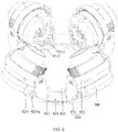
- the first bracket 921 is movably arranged on the fixing disc 910 and is movable along a circular edge of the fixing disc 910. The movement of the first bracket 921 will drive the lens 500 to move, so as to adjust the position of the lens 500 on the fixing disc 910.
- a supporting mechanism 300 is arranged between the main casing assembly 100 and the flat portion 210. One end of the supporting mechanism 300 is in supporting contact with the main casing assembly 100, and the other end of the supporting mechanism 300 passes through the fixing disc 910 and is in supporting contact with the flat portion 200.
- the supporting mechanism 300, the curved portion 220 and the flat portion 210 constitute a lens accommodating space 400 that is used to accommodate the lenses 500.
- the lens accommodating space 400 is an annular space.
- the transparent cover 200 is mounted on the main casing assembly 100 and includes a flat portion 210 and a curved portion 220.
- One end of the supporting mechanism 300 is in supporting contact with the main casing assembly 100, and the other end of the supporting mechanism is in supporting contact with the flat portion 200 so as to support the transparent cover 200.
- the transparent cover 200 will be less deformed when subjected to an external force. It can be seen that the multi-lens camera disclosed in the embodiment of the present application can solve the problem of the transparent cover of a multi-lens camera having poor resistance to deformation described in the background.
- the lens regulator 900 is arranged within the space formed by the transparent cover 200 and the main casing assembly 100.
- the lens bracket 920 includes a first bracket 921, which is movable along the circumferential direction of the fixing disc 910 to drive the lens 500 to move so as to realize P-direction adjustment. That is, the lens 500 is driven to move in a plane parallel to a disc surface of the fixing disc 910.
- the supporting mechanism 300 may include a supporting body 310 and an elastic pad 320.
- One end of the supporting body 310 may be fixed on the main casing assembly 100, the other end thereof passes through the fixing disc 910.
- the elastic pad 320 is supported between the other end of the supporting body 310 and the flat portion 210.
- the supporting body 310 is a main supporting member, and is supported on the flat portion 210 via the elastic pad 320.
- the elastic pad 320 can ensure that the supporting mechanism 300 is in elastic contact with the transparent cover 200, and avoid the rigid contact between the transparent cover 200 and the supporting body 310 when the transparent cover is impacted, and thus can further reduce the probability of the transparent cover 200 being broken.
- the main casing assembly 100 generally includes a plurality of components, and one end of the supporting body 310 may be fixedly connected with at least one of the plurality of components included in the main casing assembly 100, and thus be fixedly connected with the main casing assembly 100.
- the elastic pad 320 may be sleeved on the other end of the supporting body 310.
- the elastic pad 320 and the supporting body 310 are distributed one above the other during the mounting process. That is, the supporting body 310 is located above the elastic pad 320.
- the operator assembles the transparent cover 200 after mounting the elastic pad 320 on the supporting body 310.
- the elastic pad 320 may be sleeved on the outer side of the supporting body 310 or may be sleeved on the inner side of the supporting body 310.
- an anti-dropping belt 330 may be connected between the elastic pad 320 and the supporting body 310.
- the anti-dropping belt 330 may be an elastic belt, and elastic protrusions 331 may be provided on the edges of both sides in the middle of the anti-dropping belt 330.
- the anti-dropping belt 330 can be clamped in the connection hole in the supporting body 310 through the elastic protrusions 331, so as to realize the connection.
- a deformation hole 332 may be provided in the middle of the anti-dropping belt 330. When the elastic protrusion 331 is pressed, the deformation hole 332 will be deformed, so that the elastic protrusion 331 is more easily deformed and clamped in the connection hole.
- the main casing assembly 100 may include a main casing 110 and an inner baffle 120 arranged at a top opening of the main casing 110.
- a mainboard cavity 130 is formed between the inner baffle 120 and the main casing 110, and a mainboard 140 is arranged within the mainboard cavity 130.
- the mainboard 140 is a main working circuit of the multi-lens camera.
- the supporting mechanism 300 is arranged between the inner baffle 120 and the flat portion 210. The above structure can realize the arrangement of the mainboard 140, and at the same time can better realize the arrangement of the supporting mechanism 300.
- the supporting body 310 may be a cylinder, having one end as an open end and the other end as a closed end.
- the elastic pad 320 can only be sleeved on the outside of the other end of the supporting body 310.
- the inner baffle 120 may be provided with a through hole. The open end is fixed on the inner baffle 120, and may be communicated with the mainboard cavity 130 through the through hole.
- the mainboard 140 may include a PCB board 141, which may pass through the through hole and the open end successively from the mainboard cavity 130 and extend into the inner cavity of the supporting body 310.
- the supporting body 310 with the above structure can accommodate the PCB board 141 of the mainboard 140, and can thereby improve the structural compactness for the multi-lens camera.
- the closed end of the supporting body 310 may be provided with an interface 311 that can be connected with the PCB board 141.
- the connection with electronic components on the PCB board 141 through the interface 311 can be used by a user to realize the control or data transmission.
- the elastic pad 320 may be detachably mounted at the closed end, and can be removed by an operator to expose the interface 311 during the operation or output transmission.
- the elastic pad 320 may be detachably and sealingly mounted at the closed end of the supporting body 310 in order to improve the water-proof and dust-proof effects.
- the main casing 110 has a bottom wall opposite to the supporting body 310, and may be provided with a fixing post 111 that is supported between the bottom wall of the main casing 110 and the supporting body 310.
- a fixing post 111 there may be a plurality of fixing posts 111.
- the plurality of fixing post 111 may be arranged dispersedly, and may be fixedly connected to the supporting body 310 through screws.
- the plurality of fixing posts 111 may be fixedly connected to the supporting body 310 through other fasteners, which are not limited to the screws, and the types of fasteners are not limited in the embodiment of the present application.
- a threaded hole 111a may be opened in a fixing post 111, and a connection hole 121 may be opened in the inner baffle 120.
- a screw passes through the connection hole 121 in the inner baffle 120 and is fixedly connected with the threaded hole 111a.
- the transparent cover 200 may be fixed on the main casing assembly 100 in various manners.
- the transparent cover 200 is fixed on the main casing assembly 100 through a pressing cover 600 and a press ring 700; wherein the transparent cover 200 has an annular edge 221 extending outwards, and the pressing cover 600 is fixed on the main casing assembly 100.
- the press ring 700 is clamped between the main casing assembly 100 and the pressing cover 600, and the annular edge 221 is clamped between the pressing cover 600 and the press ring 700.
- the above-mentioned method of fixing the transparent cover 200 by clamping can avoid opening the connection hole in the transparent cover 200, and can thus better ensure the overall strength of the transparent cover 200.
- the pressing cover 600 and the press ring 700 may be fixedly connected to the main casing 110 through a threaded connection.
- the pressing cover 600 may be an annular member
- the press ring 700 may be an annular sheet metal member which has a better strength and a better heat dissipation performance.
- Seals may be arranged between the pressing cover 600 and the annular edge 221 and between the pressing cover 600 and the main casing assembly 100. The seals are fixed with the fixing of the pressing cover 600, the press ring 700 and the transparent cover 200. The arrangement of the above-mentioned seals can ensure a better sealing performance of the multi-lens camera, such that the multi-lens camera has a higher level of waterproof, dustproof and explosion-proof.
- a seal 800 is arranged between the pressing cover 600 and the annular edge 221.
- the pressing cover 600 includes a cover body 610, and a connection portion 620 and a pressing portion 630 that are arranged on the cover body 610.
- the connection portion 620 is fixedly connected to the edge of the main casing 110.
- a pressing space is formed between the cover body 610 and the edge of the main casing 110, and the press ring 700 is clamped between the pressing portion 630 and the edge of main casing 110.
- the pressing portion 630 may be a protrusion extending outwards from the cover body 610.
- the connection portion 620 is fixed to the edge of the main casing 110, and the pressing portion 630 presses the press ring 700, thereby realizing the mounting of the press ring 700.
- one of the first bracket 921 and the fixing disc 910 is provided with first tooth slots, and the other one of them is provided with first meshing teeth, and the first tooth slots are engaged with the first meshing teeth.
- the first bracket 921 is connected to the fixing disc 910 through the engagement between the first tooth slots and the first meshing teeth.
- a lens 500 is mounted on a first bracket 921, and can then move on the fixing disc 910 together with the first bracket 921, thereby adjusting the position of the lens 500 on the fixing disc 910.
- the first bracket 921 is connected to the fixing disc 910 through the engagement between the first tooth slots and the first meshing teeth.
- the operator can drive the first bracket 921 to move by applying a certain force during the adjustment.
- the first tooth slots and the first meshing teeth move relative to each other during the movement of the first bracket 921.
- the engagement between the first tooth slots and the first meshing teeth can ensure that the first bracket 921 is positioned at the adjusted position, and finally the adjustment of the lens 500 is completed.
- the circular edge of the fixing disc 910 is partially or entirely provided with the first tooth slots 911, and correspondingly, the first bracket 921 is provided with the first meshing teeth 9211a.
- the first bracket 921 can move along the circumferential direction of the fixing disc 910, and thus can rotate along the circumferential direction of the fixing disc 910.
- the rotation of the first bracket 921 drives the lens 500 to rotate, and can thereby adjust the position of the lens 500 on the fixing disc 910.
- the position adjustment is performed in a disc surface parallel to the fixing disc 910, which is the P-direction adjustment of the lens 500.
- the first tooth slots 911 may be arranged on the first bracket 921, and correspondingly, the first meshing teeth 9211a are arranged on the fixing disc 910.
- the first bracket 921 may include an elastic connection portion 9211.
- the elastic connection portion 9211 may be provided with the first meshing teeth 9211a that are engaged with the first tooth slots 911.
- the engagement between the first tooth slots and the first meshing teeth means that they are fixed to each other without any relative movement therebetween when no external force is present.
- the first tooth slots or the first meshing teeth are elastically deformed due to an external force, they are disengaged, and thsu the first tooth slots and the second meshing teeth can move relative to each other.
- the first bracket 921 can thus move along the circumferential direction of the fixing disc 910, that is, the first bracket 921 can rotate along the circumferential direction of the fixing disc 910.
- the elasticity of the elastic connection portion 9211 ensures a better flexibility in the engagement between the first tooth slots 911 and the first meshing teeth 9211a. Under the action of an external force, the elastic connection portion 9211 will be deformed elastically, thus the first meshing teeth 9211a and the first tooth slots 911 are disengaged, so that they can rotate relative to each other.
- the rotation of the first bracket 921 along the circumferential direction of the fixing disc 910 can be implemented in various manners.
- the first bracket 921 may be rolled along the circumferential direction of the fixing disc 910 so as to rotate, and the first bracket 921 may also slide along the circumferential direction of the fixing disc 910 so as to rotate.
- an annular slideway may be provided on the fixing disc 910.
- the first bracket 921 is in a positioning engagement with the annular slideway in a direction perpendicular to the disc surface of the fixing disc 910, and the first bracket 921 is slidably engaged with the fixing disc 910 in the circumferential direction of the fixing disc 910.
- the positioning engagement of the first bracket 921 with the annular slideway in the direction perpendicular to the disc surface of the fixing disc means that the first bracket 921 cannot move relative to the fixing disc 810 in a direction perpendicular to the disc surface, and can only move along the circumferential direction of the fixing disc 910, so as to realize the rotation.
- the positioning engagement of the first bracket 921 with the annular slideway in the direction perpendicular to the disc surface of the fixing disc 910 means that the first bracket 921 cannot move relative to the fixing disc 910 in a direction perpendicular to the disc surface of the fixing disc 910.
- the annular slideway can be formed on the fixing disc 910 in various manners.
- the annular slideway is formed on the disc surface of the fixing disc 910.
- an avoidance hole 912 is provided in the center of the fixing disc 910.
- the avoidance hole 912 may penetrate the fixing disc 910.
- the formation of the avoidance hole 912 makes the entire fixing disc 910 to be an annular structural member which may be used as an annular slideway; the first bracket 921 moves along the annular structural member, such that the first bracket 921 can rotate in the circumferential direction of the fixing disc 910.
- the first bracket 921 may include a connection base 9212 and a first catch 9213.
- the connection base 9212 is attached on a side surface of the fixing disc 910, the first catch 9213 is fixedly connected to the connection base 9212 and passes through the avoidance hole 912 to clamp the fixing disc 910.
- the connection base 9212 and the first catch 9213 are engaged with the two side surfaces of the fixing disc 910 respectively, so that the first bracket 921 can be assembled on the fixing disc 910.
- the connection base 9212 can slide relative to one side surface of the fixing disc 910.
- the first catch 9213 can slide relative to the other side surface of the fixing disc 910.
- the elastic connection portion 9211 may be a part of the connection base 9212 or the first catch 9213, and may also be separate from the connection base 9212 and the first catch 9213.
- the first bracket 921 may include a connection base 9212 and an elastic connection portion 9211.
- the elastic connection portion 9211 is a first elastic arm, having one end fixed on the connection base 9212 and the other end as a free end.
- the free end of the first elastic arm may be located outside the circular edge of the fixing disc 910.
- the free end of the first elastic arm can be elastically deformed relative to the connection base 9212, so as to be disengaged therefrom to realize the relative rotation between the first bracket 921 and the fixing disc 910.
- the first bracket 921 and the fixing disc 910 is provided with a tightening portion that can be tightly attached to the other one of the first bracket and the fixing disc.
- the tightening portion may include a first tightening protrusion 9212a and/or a second elastic arm 9212b.
- the first bracket 921 includes a connection base 9212.
- the connection base 9212 is attached to the disc surface of the fixing disc 810, and has a bottom surface that is attached to the fixing disc 910.
- the bottom surface may be provided with the first tightening protrusion 9212a and the second elastic arm 9212b that together enable tightening attachment between the first bracket 921 and the fixing disc 910.
- the plurality of lens brackets 920 may be distributed along the circumferential direction of the fixing disc 910.
- the plurality of lens brackets 920 may be dispersedly arranged along the circumferential direction of the fixing disc 910.
- a lens bracket 920 may further include a second bracket 922 that is arranged on the first bracket 921.
- the second bracket 922 can be rotatably engaged with the lens 500 such that the lens 500 can rotate about its own axis, so as to achieve the purpose of adjusting the lens 500, i.e., in R-direction.
Landscapes
- Physics & Mathematics (AREA)
- General Physics & Mathematics (AREA)
- Engineering & Computer Science (AREA)
- Multimedia (AREA)
- Signal Processing (AREA)
- Accessories Of Cameras (AREA)
- Studio Devices (AREA)
- Lens Barrels (AREA)
Applications Claiming Priority (2)
| Application Number | Priority Date | Filing Date | Title |
|---|---|---|---|
| CN201711452322.XA CN109981994B (zh) | 2017-12-27 | 2017-12-27 | 多目摄像机 |
| PCT/CN2018/098580 WO2019128234A1 (zh) | 2017-12-27 | 2018-08-03 | 多目摄像机 |
Publications (3)
| Publication Number | Publication Date |
|---|---|
| EP3734963A1 true EP3734963A1 (de) | 2020-11-04 |
| EP3734963A4 EP3734963A4 (de) | 2021-02-24 |
| EP3734963B1 EP3734963B1 (de) | 2023-10-25 |
Family
ID=67065029
Family Applications (1)
| Application Number | Title | Priority Date | Filing Date |
|---|---|---|---|
| EP18896148.6A Active EP3734963B1 (de) | 2017-12-27 | 2018-08-03 | Mehrkopfkamera |
Country Status (4)
| Country | Link |
|---|---|
| US (1) | US11272123B2 (de) |
| EP (1) | EP3734963B1 (de) |
| CN (1) | CN109981994B (de) |
| WO (1) | WO2019128234A1 (de) |
Cited By (1)
| Publication number | Priority date | Publication date | Assignee | Title |
|---|---|---|---|---|
| EP3734358A4 (de) * | 2018-04-04 | 2021-02-24 | Hangzhou Hikvision Digital Technology Co., Ltd. | Mehrlinsenkamera und linseneinstellvorrichtung dafür |
Families Citing this family (6)
| Publication number | Priority date | Publication date | Assignee | Title |
|---|---|---|---|---|
| WO2019140820A1 (zh) * | 2018-01-22 | 2019-07-25 | 杭州海康威视数字技术股份有限公司 | 一种透明罩及摄像光学系统 |
| CN110347003A (zh) * | 2018-04-04 | 2019-10-18 | 杭州海康威视数字技术股份有限公司 | 多目摄像机 |
| US11108940B2 (en) * | 2018-04-11 | 2021-08-31 | Hangzhou Hikvision Digital Technology Co., Ltd. | Multi-view camera and lens adjustment device |
| USD958865S1 (en) * | 2019-09-12 | 2022-07-26 | Axis Ab | Camera |
| EP3799002A1 (de) | 2019-09-26 | 2021-03-31 | Axis AB | Dome-kamera mit zwei köpfen |
| CN113938592A (zh) * | 2021-10-15 | 2022-01-14 | 深圳市圆周率软件科技有限责任公司 | 摄像机构和头盔 |
Family Cites Families (13)
| Publication number | Priority date | Publication date | Assignee | Title |
|---|---|---|---|---|
| KR20040060378A (ko) * | 2002-12-30 | 2004-07-06 | 엘지전자 주식회사 | 이동통신 단말기 카메라케이스의 카메라모듈지지구조 |
| GB0308757D0 (en) * | 2003-04-16 | 2003-05-21 | Murphy David B | Modified lamp post |
| JP2011124622A (ja) * | 2009-12-08 | 2011-06-23 | Canon Inc | 雲台撮影システム |
| CN202735674U (zh) * | 2012-07-11 | 2013-02-13 | 中国地质大学(武汉) | 一种可绕托盘360°旋转的摄像系统 |
| EP2887328B1 (de) * | 2013-12-19 | 2016-04-20 | Axis AB | Auf einer Schiene mit vorbestimmten Befestigungspunkten montierte Überwachungsvorrichtungen |
| CN203708382U (zh) * | 2014-01-17 | 2014-07-09 | 温州职业技术学院 | 高速全方位跟踪监测系统 |
| US9578242B2 (en) * | 2014-04-11 | 2017-02-21 | Samsung Electro-Mechanics Co., Ltd. | Camera module |
| US9438782B2 (en) * | 2014-06-09 | 2016-09-06 | Arecont Vision, Llc. | Omnidirectional user configurable multi-camera housing |
| CN104880211B (zh) * | 2015-05-15 | 2018-03-02 | 湖北工业大学 | 一种用于视觉检测的极坐标复合式相机机架 |
| EP3168819B1 (de) | 2015-11-16 | 2017-12-27 | Axis AB | Schutzglocke für überwachungskamerasystem |
| CN106641629B (zh) | 2016-12-28 | 2019-07-26 | 山东诚丰电子工程有限公司 | 一种机房全面监控装置 |
| CN207573492U (zh) | 2017-12-27 | 2018-07-03 | 杭州海康威视数字技术股份有限公司 | 多目摄像机 |
| CN207573503U (zh) | 2017-12-27 | 2018-07-03 | 杭州海康威视数字技术股份有限公司 | 多目摄像机及多目摄像机的镜头调节装置 |
-
2017
- 2017-12-27 CN CN201711452322.XA patent/CN109981994B/zh active Active
-
2018
- 2018-08-03 US US16/769,978 patent/US11272123B2/en active Active
- 2018-08-03 WO PCT/CN2018/098580 patent/WO2019128234A1/zh not_active Ceased
- 2018-08-03 EP EP18896148.6A patent/EP3734963B1/de active Active
Cited By (1)
| Publication number | Priority date | Publication date | Assignee | Title |
|---|---|---|---|---|
| EP3734358A4 (de) * | 2018-04-04 | 2021-02-24 | Hangzhou Hikvision Digital Technology Co., Ltd. | Mehrlinsenkamera und linseneinstellvorrichtung dafür |
Also Published As
| Publication number | Publication date |
|---|---|
| CN109981994B (zh) | 2020-06-26 |
| CN109981994A (zh) | 2019-07-05 |
| US11272123B2 (en) | 2022-03-08 |
| EP3734963A4 (de) | 2021-02-24 |
| WO2019128234A1 (zh) | 2019-07-04 |
| US20200389603A1 (en) | 2020-12-10 |
| EP3734963B1 (de) | 2023-10-25 |
Similar Documents
| Publication | Publication Date | Title |
|---|---|---|
| US11272123B2 (en) | Multi-lens camera | |
| EP3557859B1 (de) | Multilinsenkamera | |
| US10996545B2 (en) | Aperture switching device, camera device and electronic apparatus | |
| KR102364279B1 (ko) | 멀티 렌즈 카메라 및 렌즈 조절 장치 | |
| US11525973B2 (en) | Multi-lens camera | |
| US11418718B2 (en) | Video camera | |
| US9635225B2 (en) | Imaging device | |
| EP3687142B1 (de) | Kameramodul und endgerät | |
| CN208079236U (zh) | 多目摄像机及多目摄像机的镜头调节装置 | |
| CN109981996B (zh) | 多目摄像机 | |
| US20070147830A1 (en) | Imaging apparatus | |
| CN109451227A (zh) | 一种摄像机 | |
| CN214069999U (zh) | 一种镜头保护罩及拍摄装置 | |
| US11381721B2 (en) | Multi-lens camera and lens adjusting device therefor | |
| CN110365870B (zh) | 多目摄像机 | |
| US20220121089A1 (en) | Mount module with waterproofness and image pickup apparatus equipped with mount module | |
| CN108490717B (zh) | 全景相机壳体以及全景相机装置 | |
| CN206407154U (zh) | 无人机单轴镜头安装结构 | |
| CN111856844B (zh) | 支架系统及拍摄装置 | |
| CN220629381U (zh) | 一种保护装置 | |
| CN116088288B (zh) | 显示模组和腕戴设备 | |
| CN214796570U (zh) | 一种显示模块快速安装锁紧结构 | |
| WO2011072604A1 (en) | System for removably mounting photographic accessory to portable photographic apparatus |
Legal Events
| Date | Code | Title | Description |
|---|---|---|---|
| STAA | Information on the status of an ep patent application or granted ep patent |
Free format text: STATUS: THE INTERNATIONAL PUBLICATION HAS BEEN MADE |
|
| PUAI | Public reference made under article 153(3) epc to a published international application that has entered the european phase |
Free format text: ORIGINAL CODE: 0009012 |
|
| STAA | Information on the status of an ep patent application or granted ep patent |
Free format text: STATUS: REQUEST FOR EXAMINATION WAS MADE |
|
| 17P | Request for examination filed |
Effective date: 20200602 |
|
| AK | Designated contracting states |
Kind code of ref document: A1 Designated state(s): AL AT BE BG CH CY CZ DE DK EE ES FI FR GB GR HR HU IE IS IT LI LT LU LV MC MK MT NL NO PL PT RO RS SE SI SK SM TR |
|
| AX | Request for extension of the european patent |
Extension state: BA ME |
|
| A4 | Supplementary search report drawn up and despatched |
Effective date: 20210121 |
|
| RIC1 | Information provided on ipc code assigned before grant |
Ipc: G03B 17/56 20210101ALI20210115BHEP Ipc: G03B 17/00 20210101ALI20210115BHEP Ipc: G03B 37/04 20210101ALI20210115BHEP Ipc: H04N 5/247 20060101AFI20210115BHEP Ipc: H04N 5/225 20060101ALI20210115BHEP Ipc: G03B 17/02 20210101ALI20210115BHEP |
|
| DAV | Request for validation of the european patent (deleted) | ||
| DAX | Request for extension of the european patent (deleted) | ||
| STAA | Information on the status of an ep patent application or granted ep patent |
Free format text: STATUS: EXAMINATION IS IN PROGRESS |
|
| 17Q | First examination report despatched |
Effective date: 20220609 |
|
| REG | Reference to a national code |
Ref country code: DE Free format text: PREVIOUS MAIN CLASS: H04N0005247000 Ipc: H04N0023500000 Ref country code: DE Ref legal event code: R079 Ref document number: 602018060178 Country of ref document: DE Free format text: PREVIOUS MAIN CLASS: H04N0005247000 Ipc: H04N0023500000 |
|
| GRAP | Despatch of communication of intention to grant a patent |
Free format text: ORIGINAL CODE: EPIDOSNIGR1 |
|
| STAA | Information on the status of an ep patent application or granted ep patent |
Free format text: STATUS: GRANT OF PATENT IS INTENDED |
|
| RIC1 | Information provided on ipc code assigned before grant |
Ipc: G03B 17/02 20060101ALI20230427BHEP Ipc: G03B 17/56 20060101ALI20230427BHEP Ipc: G03B 37/04 20060101ALI20230427BHEP Ipc: G03B 17/00 20060101ALI20230427BHEP Ipc: H04N 23/90 20230101ALI20230427BHEP Ipc: H04N 23/51 20230101ALI20230427BHEP Ipc: H04N 23/50 20230101AFI20230427BHEP |
|
| INTG | Intention to grant announced |
Effective date: 20230516 |
|
| GRAS | Grant fee paid |
Free format text: ORIGINAL CODE: EPIDOSNIGR3 |
|
| GRAA | (expected) grant |
Free format text: ORIGINAL CODE: 0009210 |
|
| STAA | Information on the status of an ep patent application or granted ep patent |
Free format text: STATUS: THE PATENT HAS BEEN GRANTED |
|
| AK | Designated contracting states |
Kind code of ref document: B1 Designated state(s): AL AT BE BG CH CY CZ DE DK EE ES FI FR GB GR HR HU IE IS IT LI LT LU LV MC MK MT NL NO PL PT RO RS SE SI SK SM TR |
|
| REG | Reference to a national code |
Ref country code: GB Ref legal event code: FG4D |
|
| REG | Reference to a national code |
Ref country code: CH Ref legal event code: EP |
|
| REG | Reference to a national code |
Ref country code: DE Ref legal event code: R096 Ref document number: 602018060178 Country of ref document: DE |
|
| REG | Reference to a national code |
Ref country code: IE Ref legal event code: FG4D |
|
| P01 | Opt-out of the competence of the unified patent court (upc) registered |
Effective date: 20231129 |
|
| REG | Reference to a national code |
Ref country code: LT Ref legal event code: MG9D |
|
| REG | Reference to a national code |
Ref country code: NL Ref legal event code: MP Effective date: 20231025 |
|
| REG | Reference to a national code |
Ref country code: AT Ref legal event code: MK05 Ref document number: 1625908 Country of ref document: AT Kind code of ref document: T Effective date: 20231025 |
|
| PG25 | Lapsed in a contracting state [announced via postgrant information from national office to epo] |
Ref country code: NL Free format text: LAPSE BECAUSE OF FAILURE TO SUBMIT A TRANSLATION OF THE DESCRIPTION OR TO PAY THE FEE WITHIN THE PRESCRIBED TIME-LIMIT Effective date: 20231025 |
|
| PG25 | Lapsed in a contracting state [announced via postgrant information from national office to epo] |
Ref country code: GR Free format text: LAPSE BECAUSE OF FAILURE TO SUBMIT A TRANSLATION OF THE DESCRIPTION OR TO PAY THE FEE WITHIN THE PRESCRIBED TIME-LIMIT Effective date: 20240126 |
|
| PG25 | Lapsed in a contracting state [announced via postgrant information from national office to epo] |
Ref country code: IS Free format text: LAPSE BECAUSE OF FAILURE TO SUBMIT A TRANSLATION OF THE DESCRIPTION OR TO PAY THE FEE WITHIN THE PRESCRIBED TIME-LIMIT Effective date: 20240225 |
|
| PG25 | Lapsed in a contracting state [announced via postgrant information from national office to epo] |
Ref country code: LT Free format text: LAPSE BECAUSE OF FAILURE TO SUBMIT A TRANSLATION OF THE DESCRIPTION OR TO PAY THE FEE WITHIN THE PRESCRIBED TIME-LIMIT Effective date: 20231025 |
|
| PG25 | Lapsed in a contracting state [announced via postgrant information from national office to epo] |
Ref country code: AT Free format text: LAPSE BECAUSE OF FAILURE TO SUBMIT A TRANSLATION OF THE DESCRIPTION OR TO PAY THE FEE WITHIN THE PRESCRIBED TIME-LIMIT Effective date: 20231025 |
|
| PG25 | Lapsed in a contracting state [announced via postgrant information from national office to epo] |
Ref country code: ES Free format text: LAPSE BECAUSE OF FAILURE TO SUBMIT A TRANSLATION OF THE DESCRIPTION OR TO PAY THE FEE WITHIN THE PRESCRIBED TIME-LIMIT Effective date: 20231025 |
|
| PG25 | Lapsed in a contracting state [announced via postgrant information from national office to epo] |
Ref country code: LT Free format text: LAPSE BECAUSE OF FAILURE TO SUBMIT A TRANSLATION OF THE DESCRIPTION OR TO PAY THE FEE WITHIN THE PRESCRIBED TIME-LIMIT Effective date: 20231025 Ref country code: IS Free format text: LAPSE BECAUSE OF FAILURE TO SUBMIT A TRANSLATION OF THE DESCRIPTION OR TO PAY THE FEE WITHIN THE PRESCRIBED TIME-LIMIT Effective date: 20240225 Ref country code: GR Free format text: LAPSE BECAUSE OF FAILURE TO SUBMIT A TRANSLATION OF THE DESCRIPTION OR TO PAY THE FEE WITHIN THE PRESCRIBED TIME-LIMIT Effective date: 20240126 Ref country code: ES Free format text: LAPSE BECAUSE OF FAILURE TO SUBMIT A TRANSLATION OF THE DESCRIPTION OR TO PAY THE FEE WITHIN THE PRESCRIBED TIME-LIMIT Effective date: 20231025 Ref country code: BG Free format text: LAPSE BECAUSE OF FAILURE TO SUBMIT A TRANSLATION OF THE DESCRIPTION OR TO PAY THE FEE WITHIN THE PRESCRIBED TIME-LIMIT Effective date: 20240125 Ref country code: AT Free format text: LAPSE BECAUSE OF FAILURE TO SUBMIT A TRANSLATION OF THE DESCRIPTION OR TO PAY THE FEE WITHIN THE PRESCRIBED TIME-LIMIT Effective date: 20231025 Ref country code: PT Free format text: LAPSE BECAUSE OF FAILURE TO SUBMIT A TRANSLATION OF THE DESCRIPTION OR TO PAY THE FEE WITHIN THE PRESCRIBED TIME-LIMIT Effective date: 20240226 |
|
| PG25 | Lapsed in a contracting state [announced via postgrant information from national office to epo] |
Ref country code: SE Free format text: LAPSE BECAUSE OF FAILURE TO SUBMIT A TRANSLATION OF THE DESCRIPTION OR TO PAY THE FEE WITHIN THE PRESCRIBED TIME-LIMIT Effective date: 20231025 Ref country code: RS Free format text: LAPSE BECAUSE OF FAILURE TO SUBMIT A TRANSLATION OF THE DESCRIPTION OR TO PAY THE FEE WITHIN THE PRESCRIBED TIME-LIMIT Effective date: 20231025 Ref country code: PL Free format text: LAPSE BECAUSE OF FAILURE TO SUBMIT A TRANSLATION OF THE DESCRIPTION OR TO PAY THE FEE WITHIN THE PRESCRIBED TIME-LIMIT Effective date: 20231025 Ref country code: NO Free format text: LAPSE BECAUSE OF FAILURE TO SUBMIT A TRANSLATION OF THE DESCRIPTION OR TO PAY THE FEE WITHIN THE PRESCRIBED TIME-LIMIT Effective date: 20240125 Ref country code: LV Free format text: LAPSE BECAUSE OF FAILURE TO SUBMIT A TRANSLATION OF THE DESCRIPTION OR TO PAY THE FEE WITHIN THE PRESCRIBED TIME-LIMIT Effective date: 20231025 Ref country code: HR Free format text: LAPSE BECAUSE OF FAILURE TO SUBMIT A TRANSLATION OF THE DESCRIPTION OR TO PAY THE FEE WITHIN THE PRESCRIBED TIME-LIMIT Effective date: 20231025 |
|
| PG25 | Lapsed in a contracting state [announced via postgrant information from national office to epo] |
Ref country code: DK Free format text: LAPSE BECAUSE OF FAILURE TO SUBMIT A TRANSLATION OF THE DESCRIPTION OR TO PAY THE FEE WITHIN THE PRESCRIBED TIME-LIMIT Effective date: 20231025 |
|
| PG25 | Lapsed in a contracting state [announced via postgrant information from national office to epo] |
Ref country code: CZ Free format text: LAPSE BECAUSE OF FAILURE TO SUBMIT A TRANSLATION OF THE DESCRIPTION OR TO PAY THE FEE WITHIN THE PRESCRIBED TIME-LIMIT Effective date: 20231025 |
|
| REG | Reference to a national code |
Ref country code: DE Ref legal event code: R097 Ref document number: 602018060178 Country of ref document: DE |
|
| PG25 | Lapsed in a contracting state [announced via postgrant information from national office to epo] |
Ref country code: SK Free format text: LAPSE BECAUSE OF FAILURE TO SUBMIT A TRANSLATION OF THE DESCRIPTION OR TO PAY THE FEE WITHIN THE PRESCRIBED TIME-LIMIT Effective date: 20231025 |
|
| PG25 | Lapsed in a contracting state [announced via postgrant information from national office to epo] |
Ref country code: SM Free format text: LAPSE BECAUSE OF FAILURE TO SUBMIT A TRANSLATION OF THE DESCRIPTION OR TO PAY THE FEE WITHIN THE PRESCRIBED TIME-LIMIT Effective date: 20231025 Ref country code: SK Free format text: LAPSE BECAUSE OF FAILURE TO SUBMIT A TRANSLATION OF THE DESCRIPTION OR TO PAY THE FEE WITHIN THE PRESCRIBED TIME-LIMIT Effective date: 20231025 Ref country code: RO Free format text: LAPSE BECAUSE OF FAILURE TO SUBMIT A TRANSLATION OF THE DESCRIPTION OR TO PAY THE FEE WITHIN THE PRESCRIBED TIME-LIMIT Effective date: 20231025 Ref country code: IT Free format text: LAPSE BECAUSE OF FAILURE TO SUBMIT A TRANSLATION OF THE DESCRIPTION OR TO PAY THE FEE WITHIN THE PRESCRIBED TIME-LIMIT Effective date: 20231025 Ref country code: EE Free format text: LAPSE BECAUSE OF FAILURE TO SUBMIT A TRANSLATION OF THE DESCRIPTION OR TO PAY THE FEE WITHIN THE PRESCRIBED TIME-LIMIT Effective date: 20231025 Ref country code: DK Free format text: LAPSE BECAUSE OF FAILURE TO SUBMIT A TRANSLATION OF THE DESCRIPTION OR TO PAY THE FEE WITHIN THE PRESCRIBED TIME-LIMIT Effective date: 20231025 Ref country code: CZ Free format text: LAPSE BECAUSE OF FAILURE TO SUBMIT A TRANSLATION OF THE DESCRIPTION OR TO PAY THE FEE WITHIN THE PRESCRIBED TIME-LIMIT Effective date: 20231025 |
|
| PLBE | No opposition filed within time limit |
Free format text: ORIGINAL CODE: 0009261 |
|
| STAA | Information on the status of an ep patent application or granted ep patent |
Free format text: STATUS: NO OPPOSITION FILED WITHIN TIME LIMIT |
|
| 26N | No opposition filed |
Effective date: 20240726 |
|
| PG25 | Lapsed in a contracting state [announced via postgrant information from national office to epo] |
Ref country code: SI Free format text: LAPSE BECAUSE OF FAILURE TO SUBMIT A TRANSLATION OF THE DESCRIPTION OR TO PAY THE FEE WITHIN THE PRESCRIBED TIME-LIMIT Effective date: 20231025 |
|
| PG25 | Lapsed in a contracting state [announced via postgrant information from national office to epo] |
Ref country code: SI Free format text: LAPSE BECAUSE OF FAILURE TO SUBMIT A TRANSLATION OF THE DESCRIPTION OR TO PAY THE FEE WITHIN THE PRESCRIBED TIME-LIMIT Effective date: 20231025 |
|
| REG | Reference to a national code |
Ref country code: CH Ref legal event code: PL |
|
| PG25 | Lapsed in a contracting state [announced via postgrant information from national office to epo] |
Ref country code: LU Free format text: LAPSE BECAUSE OF NON-PAYMENT OF DUE FEES Effective date: 20240803 |
|
| PG25 | Lapsed in a contracting state [announced via postgrant information from national office to epo] |
Ref country code: CH Free format text: LAPSE BECAUSE OF NON-PAYMENT OF DUE FEES Effective date: 20240831 Ref country code: MC Free format text: LAPSE BECAUSE OF FAILURE TO SUBMIT A TRANSLATION OF THE DESCRIPTION OR TO PAY THE FEE WITHIN THE PRESCRIBED TIME-LIMIT Effective date: 20231025 |
|
| REG | Reference to a national code |
Ref country code: BE Ref legal event code: MM Effective date: 20240831 |
|
| PG25 | Lapsed in a contracting state [announced via postgrant information from national office to epo] |
Ref country code: BE Free format text: LAPSE BECAUSE OF NON-PAYMENT OF DUE FEES Effective date: 20240831 |
|
| PG25 | Lapsed in a contracting state [announced via postgrant information from national office to epo] |
Ref country code: FR Free format text: LAPSE BECAUSE OF NON-PAYMENT OF DUE FEES Effective date: 20240831 |
|
| PG25 | Lapsed in a contracting state [announced via postgrant information from national office to epo] |
Ref country code: IE Free format text: LAPSE BECAUSE OF NON-PAYMENT OF DUE FEES Effective date: 20240803 |
|
| PG25 | Lapsed in a contracting state [announced via postgrant information from national office to epo] |
Ref country code: FI Free format text: LAPSE BECAUSE OF FAILURE TO SUBMIT A TRANSLATION OF THE DESCRIPTION OR TO PAY THE FEE WITHIN THE PRESCRIBED TIME-LIMIT Effective date: 20231025 |
|
| PGFP | Annual fee paid to national office [announced via postgrant information from national office to epo] |
Ref country code: DE Payment date: 20250812 Year of fee payment: 8 |
|
| PGFP | Annual fee paid to national office [announced via postgrant information from national office to epo] |
Ref country code: GB Payment date: 20250826 Year of fee payment: 8 |
|
| PG25 | Lapsed in a contracting state [announced via postgrant information from national office to epo] |
Ref country code: CY Free format text: LAPSE BECAUSE OF FAILURE TO SUBMIT A TRANSLATION OF THE DESCRIPTION OR TO PAY THE FEE WITHIN THE PRESCRIBED TIME-LIMIT; INVALID AB INITIO Effective date: 20180803 |
|
| PG25 | Lapsed in a contracting state [announced via postgrant information from national office to epo] |
Ref country code: HU Free format text: LAPSE BECAUSE OF FAILURE TO SUBMIT A TRANSLATION OF THE DESCRIPTION OR TO PAY THE FEE WITHIN THE PRESCRIBED TIME-LIMIT; INVALID AB INITIO Effective date: 20180803 |