EP3735152B1 - Ensemble d'un panneau de meuble et d'une ferrure de déplacement avec élément de montage intégré pour le panneau mobile, le corps du meuble et les meubles comprenant un tel panneau de meuble - Google Patents
Ensemble d'un panneau de meuble et d'une ferrure de déplacement avec élément de montage intégré pour le panneau mobile, le corps du meuble et les meubles comprenant un tel panneau de meuble Download PDFInfo
- Publication number
- EP3735152B1 EP3735152B1 EP19700047.4A EP19700047A EP3735152B1 EP 3735152 B1 EP3735152 B1 EP 3735152B1 EP 19700047 A EP19700047 A EP 19700047A EP 3735152 B1 EP3735152 B1 EP 3735152B1
- Authority
- EP
- European Patent Office
- Prior art keywords
- furniture
- recess
- arrangement according
- fitting
- furniture panel
- Prior art date
- Legal status (The legal status is an assumption and is not a legal conclusion. Google has not performed a legal analysis and makes no representation as to the accuracy of the status listed.)
- Active
Links
Images




Classifications
-
- A—HUMAN NECESSITIES
- A47—FURNITURE; DOMESTIC ARTICLES OR APPLIANCES; COFFEE MILLS; SPICE MILLS; SUCTION CLEANERS IN GENERAL
- A47B—TABLES; DESKS; OFFICE FURNITURE; CABINETS; DRAWERS; GENERAL DETAILS OF FURNITURE
- A47B96/00—Details of cabinets, racks or shelf units not covered by a single one of groups A47B43/00 - A47B95/00; General details of furniture
- A47B96/20—Furniture panels or like furniture elements
- A47B96/205—Composite panels, comprising several elements joined together
-
- A—HUMAN NECESSITIES
- A47—FURNITURE; DOMESTIC ARTICLES OR APPLIANCES; COFFEE MILLS; SPICE MILLS; SUCTION CLEANERS IN GENERAL
- A47B—TABLES; DESKS; OFFICE FURNITURE; CABINETS; DRAWERS; GENERAL DETAILS OF FURNITURE
- A47B2220/00—General furniture construction, e.g. fittings
- A47B2220/0061—Accessories
- A47B2220/0069—Hinges
- A47B2220/0072—Hinges for furniture
-
- E—FIXED CONSTRUCTIONS
- E05—LOCKS; KEYS; WINDOW OR DOOR FITTINGS; SAFES
- E05D—HINGES OR SUSPENSION DEVICES FOR DOORS, WINDOWS OR WINGS
- E05D15/00—Suspension arrangements for wings
- E05D15/40—Suspension arrangements for wings supported on arms movable in vertical planes
- E05D15/401—Suspension arrangements for wings supported on arms movable in vertical planes specially adapted for overhead wings
-
- E—FIXED CONSTRUCTIONS
- E05—LOCKS; KEYS; WINDOW OR DOOR FITTINGS; SAFES
- E05D—HINGES OR SUSPENSION DEVICES FOR DOORS, WINDOWS OR WINGS
- E05D5/00—Construction of single parts, e.g. the parts for attachment
- E05D5/02—Parts for attachment, e.g. flaps
-
- E—FIXED CONSTRUCTIONS
- E05—LOCKS; KEYS; WINDOW OR DOOR FITTINGS; SAFES
- E05Y—INDEXING SCHEME ASSOCIATED WITH SUBCLASSES E05D AND E05F, RELATING TO CONSTRUCTION ELEMENTS, ELECTRIC CONTROL, POWER SUPPLY, POWER SIGNAL OR TRANSMISSION, USER INTERFACES, MOUNTING OR COUPLING, DETAILS, ACCESSORIES, AUXILIARY OPERATIONS NOT OTHERWISE PROVIDED FOR, APPLICATION THEREOF
- E05Y2201/00—Constructional elements; Accessories therefor
- E05Y2201/10—Covers; Housings
- E05Y2201/11—Covers
-
- E—FIXED CONSTRUCTIONS
- E05—LOCKS; KEYS; WINDOW OR DOOR FITTINGS; SAFES
- E05Y—INDEXING SCHEME ASSOCIATED WITH SUBCLASSES E05D AND E05F, RELATING TO CONSTRUCTION ELEMENTS, ELECTRIC CONTROL, POWER SUPPLY, POWER SIGNAL OR TRANSMISSION, USER INTERFACES, MOUNTING OR COUPLING, DETAILS, ACCESSORIES, AUXILIARY OPERATIONS NOT OTHERWISE PROVIDED FOR, APPLICATION THEREOF
- E05Y2600/00—Mounting or coupling arrangements for elements provided for in this subclass
- E05Y2600/40—Mounting location; Visibility of the elements
- E05Y2600/41—Concealed
-
- E—FIXED CONSTRUCTIONS
- E05—LOCKS; KEYS; WINDOW OR DOOR FITTINGS; SAFES
- E05Y—INDEXING SCHEME ASSOCIATED WITH SUBCLASSES E05D AND E05F, RELATING TO CONSTRUCTION ELEMENTS, ELECTRIC CONTROL, POWER SUPPLY, POWER SIGNAL OR TRANSMISSION, USER INTERFACES, MOUNTING OR COUPLING, DETAILS, ACCESSORIES, AUXILIARY OPERATIONS NOT OTHERWISE PROVIDED FOR, APPLICATION THEREOF
- E05Y2900/00—Application of doors, windows, wings or fittings thereof
- E05Y2900/20—Application of doors, windows, wings or fittings thereof for furniture, e.g. cabinets
Definitions
- the invention relates to an arrangement of a furniture panel and a movement fitting for movable furniture parts, the furniture panel having a recess and an integrated mounting element for receiving a movement fitting, the mounting element having a base and side sections protruding from the base on at least two sides of the base, and the Mounting element is inserted into the recess of the furniture panel and the recess extends from a side surface and at least one end face of the furniture panel.
- the base of the mounting element is non-positively or materially connected to a mating surface of the recess and the mounting element has means for fastening the movement fitting, with the movement fitting being able to be inserted essentially completely into the furniture panel with regard to the side surface of the furniture panel, and with moving parts of the movement fitting can be moved out of a front side of the furniture panel.
- the invention also relates to a furniture body or a piece of furniture.
- the bodies of furniture are usually formed from furniture boards based on wood or a wood-based material, such as chipboard or medium-density or high-density fiberboard (MDF - Medium Density Fiber, HDF - High Density Fiber), are made.
- Connection fittings, movement fittings or other functional fittings are used to connect the furniture panels to one another or for the articulated connection of movable furniture parts such as doors or flaps, which are collectively referred to as fittings in this context.
- Fittings are generally made from plastics and/or metal materials. Larger fittings in particular are usually placed on the furniture panels and screwed to them. They then protrude into the interior of the furniture body, which means that they are not visible when the door or flap is closed, but impair the appearance of the furniture body when the door or flap is open and reduce the usable interior volume of the furniture body.
- the pamphlet GB 1,158,961A shows, for example, a hinge with two mutually pivotable sections, each having the shape of a hinge pot. The hinge cups are inserted into corresponding recesses in furniture boards.
- the pamphlets WO 2010/060991 A1 and DE 20 2008 015732 U1 disclose connecting fittings for furniture panels, which are glued into a hole or recess in a furniture panel, in particular a lightweight furniture panel, by injecting adhesive into an adhesive channel after the fitting has been inserted.
- the pamphlet EP 2 530 227 A1 shows a hinge for pivotal connection two plate-shaped glass elements.
- the pamphlet DE 20 2014 105 730 U1 describes a furniture board in which an insert is arranged as a mounting element in a material recess, which can accommodate a movement fitting.
- the material recess can be provided with undercut sections in order to fix the insert at least in one direction perpendicular to the surface of the furniture panel. Further details on the attachment of the insert to the furniture panel or the movement fitting on the insert are not described.
- the advantage of arranging the insert in the recess in the furniture panel is that the movement fitting used is positioned completely or partially countersunk relative to the surface of the furniture panel, so that it does not protrude or protrudes less into the interior of a furniture body.
- An arrangement according to the invention of the type mentioned at the outset is characterized in that guides, in particular in the form of guide webs, are arranged or formed on the mounting element, which allow the movement fitting to be pushed in parallel to the floor.
- the guides can be arranged or formed on the floor, but also on the side sections.
- the guides allow the movement fitting to be pushed in from the front.
- a cassette-shaped mounting element can be used, which conceals the recess on the inside of the carcass.
- the fastening means can already be integrated into the furniture panel when it is being manufactured and allows the movement fitting to be fastened in a very confined space.
- the recess Through the non-positive or material connection with a counter surface the recess, it has a reinforcing (stabilizing) function for the furniture board. Because of the stabilization, the cutout (seen from the side surface of the furniture panel) can be made larger and/or deeper than would be possible without the stabilization of the furniture panel in the area of the cutout. The space available for the movement fitting within the furniture panel can thus be effectively increased despite the additional fastening means.
- the fact that the movement fitting can be inserted essentially completely into the furniture panel with regard to the side surface of the furniture panel means that the movement fitting is integrated into the furniture panel so that it does not protrude or only slightly into the interior of a furniture body.
- the expression “substantially” is to be understood in such a way that any overhang of the movement fitting is so small that the movement fitting does not impair the design of the interior of the body.
- the overhang is preferably less than 3 millimeters (mm), or in relative terms, preferably less than about 10% of the depth of the recess.
- the recess is (subsequently) introduced into the furniture panel, preferably milled or embossed.
- the furniture panel can thus initially be produced conventionally, e.g. from wood or a wood composite material, without the recess.
- the recess can then be created later. This can preferably be done from the side surface.
- the recess can be created together with the furniture board in a primary molding process, e.g. in a foaming or casting process.
- the recess has a constant depth over its area.
- this represents a form of recess that is easy to produce.
- other forms are also possible, for example a recess with a stepped depth, the recess being in the area of the movement fitting, in which moving fitting elements such as levers or the like are arranged, is lower than in other areas.
- the depth of the recess can be at least 14 mm, for example, and the thickness of the material of the furniture panel remaining in the region of the recess can be between approximately 1 and 10 mm.
- the mounting element is adhesively bonded into the recess. Bonding saves space and can be implemented even if the remaining material thickness of the furniture board is small in the area of the recess. If the bottom of the mounting element is glued to the furniture panel over the entire surface or almost over the entire surface, the material thickness of the furniture board can be particularly low in the area of the cutout, creating the maximum possible depth of installation space for the movement fitting.
- the base can have several shaped elements, e.g. spikes, which can be pressed into the opposite surface of the recess and which also create a stabilizing connection.
- shaped elements e.g. spikes
- the end face with the recess is provided with a coating on the narrow side, e.g. an edge band.
- An end face of the base is preferably aligned with the end face provided with the recess and the end face of the base is—preferably essentially completely—covered by the coating on the narrow side.
- the mounting element is made of a metallic material, with a modulus of elasticity of the metallic material being at least a factor of 10 higher than a modulus of elasticity of a furniture panel material or furniture panel composite material.
- E-modulus modulus of elasticity
- the moduli of elasticity of typical materials or composite materials of furniture panels are in the range of about 1000 to about 6500 N/mm 2 (Newton per square millimeter).
- the furniture panel of the arrangement has a cover for the movement fitting used in the mounting element, which can protrude up to a maximum of 3 mm over the side surface.
- a cover for the movement fitting used in the mounting element, which can protrude up to a maximum of 3 mm over the side surface.
- the means for fastening the movement fitting are attached to the floor.
- the means for fastening the movement fitting can, for example, be mounting bolts which protrude perpendicularly from the floor and onto which the movement fitting is fitted with corresponding mounting bores.
- the mounting bolts can each have a bore with an internal thread into which mounting screws can be screwed. In this way, the movement fitting can be easily inserted into the recess and fastened from the inside of the furniture panel on the carcass side.
- the base has at least one embossing on which the movement fitting rests. Due to the at least embossing, the contact point or the contact points of the movement fitting on the mounting element are precisely defined and it is possible to keep a height tolerance of the structural unit consisting of mounting element and movement fitting within a narrow dimensional range. Any unevenness in the bottom of the mounting element is therefore no longer relevant to the overall height.
- locking means are preferably provided, by means of which the movement fitting locks with the mounting element.
- the latching means can preferably be latching springs which are arranged or formed on the base and/or on the side sections and/or on the movement fitting.
- the detent springs can be arranged and designed in such a way that the locking of the movement fitting is released by inserting an insertion tongue of a removal tool into a gap between the mounting element and the movement fitting. In this way, the movement fitting can also be removed again if necessary for repair or maintenance or for replacement.
- a furniture body according to the invention or a piece of furniture according to the invention has a wall, in particular a side wall, which has such an arrangement of a furniture panel with an integrated mounting element and a movement fitting.
- top, bottom, left, right refer exclusively to the exemplary representation selected in the respective figures.
- front and rear refer to an orientation of the furniture body, with the front side identifying the open side of the furniture body that generally faces the user.
- FIG. 1 shows an isometric view of a wall unit, for example a kitchen, as a first exemplary embodiment of a piece of furniture with composite elements as a side wall.
- a composite element is within the scope of this application to understand an arrangement of a furniture board with an integrated functional component.
- the upper cabinet comprises a furniture body 10 with a bottom panel 11 and a top panel 12 as well as two side walls 13.
- a rear wall is preferably present for reasons of stability, among other things, but is not visible in this exemplary embodiment.
- the furniture body 10 is open at the front to gain access to the interior of the cabinet.
- a flap arrangement 20 is provided with a one-piece flap 21 in this example, in order to be able to close the opening of the furniture body 10 .
- the one-piece flap 21 is pivoted along its upper horizontal side edge.
- movement fittings 30 are provided, which are connected to the one-piece flap 21 with a lever system 33 in the upper region of the latter.
- the movement fittings 30, also referred to below as fittings 30 for short, are arranged countersunk in the respective side wall 13 (apart from the lever mechanism 33, which is extended in the illustrated open position).
- the lever system 33 is completely retracted into the side wall 13 , possibly except for assembly elements for connection to the flap 21 .
- the area within the side wall 13 in which the fitting 30 is located is in the Fig.1 at the left side wall 13 indicated by a broken line.
- the fitting 30 is provided with a cover 36 on the right-hand side wall 13 .
- the side wall 13 is characterized by side surfaces which ideally have the same surface quality throughout, at least on the outside of the furniture carcass 10 over their entire surface.
- the surface of the side panels can create design effects with different patterns, surface textures or different colors.
- the cover 36 is preferably flush with the rest of the surface of the side wall 13 on the respective inner side surface of the side walls 13 pointing towards the interior of the furniture carcass 10. It can be optically adapted or also deliberately set off optically in relation to the surface of the side wall 13.
- the side walls 13 are constructed from furniture panels 40 which have an integrated assembly element 50 for fastening the fitting 30 .
- the furniture panels 40 and thus the side walls 13 have an end face 43, which has an opening in the area of the fitting 30, into which the lever mechanism 33 of the fitting 30 dips or from which the lever mechanism 33 extends.
- the lever mechanism 33 is completely immersed in the opening, except for any fastening means with which it is connected to the flap 21, which is one-piece here.
- the structure of a suitable for the side walls 13 furniture panel 40 is in connection with 2 , 3a and 3b in a first and in connection with the 4a to 7 explained in more detail below in a second exemplary embodiment.
- FIG 2 shows an isometric side view of a furniture panel 40 with an integrated mounting element 50 and a fitting 30 and a cover 36 placed thereon in an isometric exploded view.
- the furniture board 40 is, for example, used to produce the side walls 13 in the furniture body 10 according to FIG 1 suitable.
- the furniture board 40 is usually made of wood or a wood material (chipboard, MDF, HDF) or a wood/plastic composite material. In alternative configurations, stone slabs can also be used as furniture panels.
- the furniture panel 40 has a recess 42 introduced from a side face 41 , which is also open at least in sections towards an end face 43 of the furniture panel 40 .
- the lever system 33 exits through the opening in the end face 43 .
- the mounting plate 50 is inserted into the recess 42 and connected to the furniture panel 40, in particular glued.
- the mounting element 50 has a rectangular flat bottom 51 and three side sections 52.
- the side facing the end face 43 of the furniture panel 40 remains open.
- the base 51 is preferably formed in one piece with the side sections 52 and can be made of sheet steel, for example, with the side sections 52 being bent from the base 51 .
- the mounting element 50 can thus be manufactured inexpensively, for example, as a stamped and bent part.
- the dimensions of the mounting element 50 correspond to the contour of the recess 42, so that the mounting element 50 can be inserted into the recess 42 from the side surface 41 of the furniture panel 40 with as precise a fit as possible can. Forces acting on the fitting 30 can already be introduced well into the furniture panel 40 via the mounting element 50 as a result of the precisely fitting insertion.
- connection means are additionally provided in order to fasten the mounting element 50 to the furniture panel 40 .
- the mounting element 50 can advantageously be glued into the recess 42, with the large-area base 51 being particularly suitable for gluing.
- Such a bonding not only fixes the mounting element 50, but also stabilizes the bottom of the recess 42, which under certain circumstances consists of a remaining layer of the furniture board 40 that is only a few millimeters (mm) thick.
- Gluing can also take place on the outer surfaces of the side sections 52 . Screw connections can also be provided at these points, in which screws are screwed through the side sections 52 of the mounting element 50 into the core material of the furniture panel 40 .
- Mounting bolts 53 are also arranged on the base 51, for example welded in a spot welding process or inserted through openings in the base 51 and crimped to it.
- the fitting 30 to be used has mounting bores 34 at the positions of the mounting bolts 53 and is correspondingly pushed onto the mounting bolts 53 with these mounting bores 34 .
- the mounting bolts 53 are provided with a central internal thread into which mounting screws 35 are screwed, which correspondingly secure the side plate 31 and thus the fitting 30 on the mounting bolt 53 .
- cover 36 On the fitting 30 is already associated with the cover 1 called cover 36 placed.
- it can have latching means with which it is clipped onto the side plate 31 .
- the recess 42 of the furniture panel 40 can be formed so deep that it completely accommodates the fitting 30, optionally with the cover 36.
- the area of the fitting 30, possibly with the cover 36, is then advantageous flush with the rest of the surface of the side surface 41.
- a surface that is optically almost homogeneous is created—in particular with the cover 36 in place. Nevertheless, after removing the cover 36 and loosening the assembly screws 35, the fitting 30 can be removed inwards towards the interior of the furniture body when the furniture is assembled, for example in order to be able to replace it in the event of a possible defect or wear.
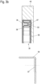
- Figure 3a shows a top view of the end face 43 of the furniture panel 40 with the mounting element 50, in which the fitting 30 is inserted and on which the cover 36 is placed.
- embossings 57 (cf. lower part of Figure 3b ) arranged on which the mounting bolts 53 are fixed.
- the contact points of the fitting 30 on the mounting element 50 are precisely defined by the embossing 57 and it is possible to keep the height tolerance of the structural unit consisting of the mounting element 50 and the fitting 30 within a narrow dimensional range. Any unevenness in the bottom 51 of the mounting element 50 is therefore irrelevant to the overall height.
- Figures 4a and 4b a second exemplary embodiment of a furniture panel 40 with an integrated mounting element 50 is shown.
- Figure 4a shows the arrangement in a side view of the side surface 41 of the furniture panel 40 and Figure 4b in an isometric oblique view.
- a recess 42 is made in the furniture panel 40, in which the mounting element 50 is inserted.
- This in turn has a flat bottom 51 which is folded on three sides, so that side sections 52 are formed. The side sections 52 end flush with the edges of the recess 42.
- Gluing of the mounting element 50 to the furniture panel 40 is preferably provided again for fastening. Reference is made to the alternative or additional fastening methods in connection with the first exemplary embodiment.
- the fitting 30 is not inserted from the side face 41 here, but pushed in from the end face 43 .
- the front opening is corresponding formed in the furniture panel 40 in such a way that the opening cross-section corresponds to the dimensions of the fitting 30 at points of its maximum installation height, so that it can be pushed in from the end face 43 .
- a guide bar 54 is arranged on the lower and on the upper side section 52 .
- the side plates 31, 32 projecting slightly upwards or downwards grip around the sides of the guide webs 54, as a result of which the fitting 30 is fixed in a direction perpendicular to the side face 41 of the furniture panel 40.
- detent springs 55 which are flared inwards and with which the fitting 30 locks in the inserted state.
- Spring elements 56 are also arranged on the rear side section 52 of the mounting element 50, seen in the direction of insertion 6 and 7 is explained.
- the furniture panel 40 with the fitting 30 inserted is shown in a manner analogous to that in FIGS Figures 4a and 4b in the Figures 5a and 5b shown. Again, the fitting 30 is aligned substantially flush with its side panel 31 pointing outwards with the side surface 41 of the furniture panel 40 .
- a cover cf. cover 36 of the first embodiment
- the insertion of the fitting 30 into the mounting element 50 is again shown as an example outside of the furniture panel 40 .
- the side plates 31, 32 are spaced apart from one another by a frame 38.
- the frame 38 runs along at least the upper and lower sides and preferably also along the rear side of the fitting 30 and together with the side plates 31, 32 forms a housing of the fitting 30.
- the frame 38 is offset slightly inwards relative to the side plates 31, 32, so that a U-shaped guide profile is formed in each case, which accommodates the corresponding guide bar 54.
- a locking recess 37 is arranged in the frame 38 at a suitable point, in which the detent spring 55 engages, so that the fitting 30 not only through the guide 54 laterally, but also in view is fixed to the direction of insertion and can no longer be easily removed from the front.
- the inserted state of the fitting 30 in the mounting element 50 is in the 7 played back.
- Next shows the 7 the attachment of a removal tool 60, which has a front handle part 61 and two strip-shaped insertion tongues 62 projecting perpendicularly therefrom and aligned parallel to one another.
- the insertion tongues 62 are inserted adjacent to the frame 38 between the side sections 52 of the mounting plate 50 and the fitting 30 and lever the detent spring 55 out of the detent recess 37.
- the fitting 30 is removed by the in 6 visible spring elements 56 supported.
- the spring elements 56 are tensioned when the fitting 30 is pushed in and spring out after the latching between the locking spring 55 and the locking recess 37 has been released and push the fitting 30 so far in the removal direction that it can then be easily gripped by a user.
- the arrangement shown in the second exemplary embodiment thus also allows the fitting 30 to be replaced when the furniture carcass or piece of furniture is mounted.
- the mounting element 50 can also be produced in several parts, in which case the detent springs 55 and spring elements 56 can be fixed separately from an elastic, resilient material.
Landscapes
- Furniture Connections (AREA)
- Connection Of Plates (AREA)
- Assembled Shelves (AREA)
Claims (21)
- Ensemble formé d'un panneau de meuble (40) et d'une ferrure de mouvement (30) pour des parties de meuble mobiles, dans lequel le panneau de meuble (40) présente une découpe (42) et un élément de montage intégré (50) pour recevoir la ferrure de mouvement (30), l'élément de montage (50) présentant un fond (51) et des parties latérales (52) qui dépassent du fond (51) sur au moins deux côtés de celui-ci, et dans lequel l'élément de montage (50) est inséré dans la découpe (42) du panneau de meuble (40) et la découpe (42) s'étend à partir d'une face latérale (41) et d'au moins une face d'extrémité (43) du panneau de meuble (40), dans lequel au moins le fond (51) de l'élément de montage (50) est assemblé par friction ou par solidarité de matière avec une surface opposée de la découpe (42) et l'élément de montage (50) présente des moyens pour fixer la ferrure de mouvement (30), dans lequel la ferrure de mouvement (30) peut être insérée à peu près complètement dans le panneau de meuble (40) et dans lequel des parties mobiles de la ferrure de mouvement (30) peuvent sortir par une face frontale (43) du panneau de meuble, des guides étant disposés ou formés dans l'élément de montage (50) pour permettre une insertion de la ferrure de mouvement (30) parallèlement au fond (51).
- Ensemble selon la revendication 1, dans lequel la découpe (42) est créée, de préférence par fraisage ou par emboutissage.
- Ensemble selon la revendication 1, dans lequel la découpe (42) est formée dès l'origine avec le panneau de meuble (40).
- Ensemble selon l'une des revendications 1 à 3, dans lequel la découpe (42) présente une profondeur constante sur son aire.
- Ensemble selon l'une des revendications 1 à 4, dans lequel l'élément de montage (50) est collé par solidarité de matière dans la découpe (42).
- Ensemble selon l'une des revendications 1 à 5, dans lequel le fond (51) présente plusieurs éléments mis en forme, par exemple des pointes, qui peuvent être enfoncés dans la surface opposée de la découpe (42).
- Ensemble selon l'une des revendications 1 à 6, dans lequel la face frontale (43) munie de la découpe (42) est dotée d'un revêtement de petit côté, par exemple d'une bande de chant collée.
- Ensemble selon la revendication 7, dans lequel une face frontale du fond (51) est orientée vers la face frontale (43) munie de la découpe (42), la face frontale du fond (51) étant couverte par le revêtement de petit côté.
- Ensemble selon l'une des revendications 1 à 8, dans lequel l'élément de montage (50) est fabriqué dans un matériau métallique dont le module d'élasticité est supérieur d'au moins un facteur 10 à celui d'un matériau du panneau de meuble ou d'un matériau composite du panneau de meuble, afin de compenser l'affaiblissement du matériau par la découpe (42).
- Ensemble selon l'une des revendications 1 à 9, dans lequel le panneau de meuble (40) présente une couverture (36) pour la ferrure de mouvement (30) insérée dans l'élément de montage (50).
- Ensemble selon la revendication 10, dans lequel la couverture (36) dépasse sur 0 mm à 3 mm de la face latérale (41).
- Ensemble selon l'une des revendications 1 à 11, dans lequel des moyens pour fixer la ferrure de mouvement (30) sont disposés sur le fond (51).
- Ensemble selon la revendication 12, dans lequel les moyens pour fixer la ferrure de mouvement (30) sont des boulons de montage (53) qui dépassent perpendiculairement du fond (51), sur lesquels la ferrure de mouvement (30) est enfichée avec des trous de montage (34).
- Ensemble selon la revendication 13, dans lequel les boulons de montage (53) présentent un alésage avec un filetage intérieur dans lequel des vis de montage (35) peuvent être vissées.
- Ensemble selon l'une des revendications 1 à 14, dans lequel le fond (51) présente au moins une gravure (57).
- Ensemble selon l'une des revendications 1 à 15, dans lequel des guides sont formés sous la forme de barrettes de guidage (54).
- Ensemble selon l'une des revendications 1 à 16, dans lequel des guides sont disposés ou formés sur les parties latérales (52).
- Ensemble selon l'une des revendications 1 à 17, dans lequel des moyens d'enclenchement sont prévus pour enclencher la ferrure de mouvement (30) avec l'élément de montage (50).
- Ensemble selon la revendication 18, dans lequel les moyens d'enclenchement sont des ressorts d'enclenchement (55) qui sont disposés ou formés sur le fond (51) et/ou sur les parties latérales (52) et/ou sur la ferrure de mouvement (30).
- Ensemble selon la revendication 19, dans lequel les ressorts d'enclenchement (55) sont disposés ou formés de telle manière que l'introduction d'une languette à insérer (62) d'un outil d'extraction (60) dans un interstice entre l'élément de montage (50) et la ferrure de mouvement (30) défasse l'enclenchement de la ferrure de mouvement (30).
- Corps de meuble (10) ou meuble avec une paroi, en particulier une paroi latérale (13), qui présente un ensemble formé d'un panneau de meuble (40) avec un élément de montage (50) intégré et d'une ferrure de mouvement (30) selon l'une des revendications 1 à 20.
Applications Claiming Priority (2)
| Application Number | Priority Date | Filing Date | Title |
|---|---|---|---|
| DE102018100206.8A DE102018100206A1 (de) | 2018-01-05 | 2018-01-05 | Möbelplatte mit integriertem Montageelement für einen Bewegungsbeschlag und Möbelkorpus und Möbel mit einer derartigen Möbelplatte |
| PCT/EP2019/050090 WO2019134936A1 (fr) | 2018-01-05 | 2019-01-03 | Panneau de meuble comprenant un élément de montage intégré pour une ferrure de déplacement et corps de meuble et meuble comprenant un tel panneau de meuble |
Publications (2)
| Publication Number | Publication Date |
|---|---|
| EP3735152A1 EP3735152A1 (fr) | 2020-11-11 |
| EP3735152B1 true EP3735152B1 (fr) | 2023-06-14 |
Family
ID=64959366
Family Applications (1)
| Application Number | Title | Priority Date | Filing Date |
|---|---|---|---|
| EP19700047.4A Active EP3735152B1 (fr) | 2018-01-05 | 2019-01-03 | Ensemble d'un panneau de meuble et d'une ferrure de déplacement avec élément de montage intégré pour le panneau mobile, le corps du meuble et les meubles comprenant un tel panneau de meuble |
Country Status (4)
| Country | Link |
|---|---|
| EP (1) | EP3735152B1 (fr) |
| CN (1) | CN111556721B (fr) |
| DE (2) | DE102018100206A1 (fr) |
| WO (1) | WO2019134936A1 (fr) |
Cited By (1)
| Publication number | Priority date | Publication date | Assignee | Title |
|---|---|---|---|---|
| EP3735153B1 (fr) * | 2018-01-05 | 2024-12-11 | ambigence GmbH & Co. KG | Procédé d'intégration d'un élément de montage pour une ferrure de déplacement dans un panneau de meuble et panneau de meuble ayant l'élément de montage intégré |
Families Citing this family (8)
| Publication number | Priority date | Publication date | Assignee | Title |
|---|---|---|---|---|
| DE102017108197B4 (de) * | 2017-04-18 | 2025-07-17 | Hettich-Oni Gmbh & Co. Kg | Möbel |
| IT201900013284A1 (it) * | 2019-07-30 | 2021-01-30 | Veneta Cucine S P A | Elemento di arredo munito di anta con meccanismo di azionamento a scomparsa |
| DE102020125759B4 (de) | 2020-10-01 | 2024-03-21 | ambigence GmbH & Co. KG | Möbelkomponente |
| AT524364B1 (de) * | 2020-11-12 | 2024-01-15 | Blum Gmbh Julius | Möbelbeschlag mit einstellbarer Montageposition einer Abdeckkappe |
| CN112530128B (zh) * | 2020-12-03 | 2022-03-18 | 国网山东省电力公司电力科学研究院 | 电缆隧道防火预警巡检系统及巡检方法 |
| AT525449B1 (de) * | 2021-12-03 | 2023-04-15 | Blum Gmbh Julius | Wand und Verfahren zum Herstellen einer Wand für einen Möbelkorpus |
| DE202023100322U1 (de) * | 2023-01-24 | 2023-02-17 | Flap Competence Center Kft | Möbel |
| EP4617461A1 (fr) * | 2024-03-11 | 2025-09-17 | FLAP Competence Center kft | Dispositif de fixation pour fixer une ferrure de meuble, ferrure de meuble dotée d'un tel dispositif de fixation et meuble doté d'une telle ferrure de meuble |
Citations (3)
| Publication number | Priority date | Publication date | Assignee | Title |
|---|---|---|---|---|
| DE202008015732U1 (de) * | 2008-11-27 | 2010-04-15 | Hettich-Heinze Gmbh & Co. Kg | Beschlag zum Festlegen einer Leichtbauplatte |
| DE102015108694A1 (de) * | 2014-06-19 | 2015-12-24 | Ernestomeda S.P.A. | Öffnungsmechanismus für Möbeltüren und mit diesem Mechanismus ausgestattetes Möbel |
| WO2018158158A1 (fr) * | 2017-02-28 | 2018-09-07 | ambigence GmbH & Co. KG | Paroi d'un corps de meuble, procédé de fabrication d'une telle paroi et corps de meuble ou meuble doté d'une telle paroi |
Family Cites Families (15)
| Publication number | Priority date | Publication date | Assignee | Title |
|---|---|---|---|---|
| CH463998A (de) * | 1966-05-13 | 1968-10-15 | Guenter & Co Oni Metall | Klappenscharnier |
| FR2404607A1 (fr) * | 1977-09-29 | 1979-04-27 | Deknudt Frans | Dispositif d'assemblage monolithique d'un corps de verre et d'un blochet |
| FR2438147A1 (fr) * | 1978-10-04 | 1980-04-30 | Chereau Jean | Charniere encastree perfectionnee |
| JPH095598A (ja) * | 1995-06-22 | 1997-01-10 | Sumitomo Electric Ind Ltd | 空気圧送型光ファイバ用パイプの接続部構造 |
| DE102005057150A1 (de) * | 2005-11-30 | 2007-06-06 | BSH Bosch und Siemens Hausgeräte GmbH | Kühl- bzw. Gefrierschrank mit Verstärkungsrahmen |
| DE202006004873U1 (de) * | 2006-03-28 | 2006-06-01 | MEPLA-WERKE LAUTENSCHLäGER GMBH & CO. KG | Scharnier für die verschwenkbare Anlenkung von Klappen oder Türflügeln am Korpus von Möbelstücken |
| DE202007015604U1 (de) * | 2007-11-09 | 2009-03-26 | Hettich-Heinze Gmbh & Co. Kg | Verbindungsbeschlag für Leichtbauplatten |
| DE202008015728U1 (de) * | 2008-11-27 | 2010-04-15 | Hettich-Heinze Gmbh & Co. Kg | Beschlag |
| EP2530227B1 (fr) * | 2011-05-31 | 2013-05-29 | Provex Industrie GmbH | Charnière à fixations affleurantes pour éléments de vitrerie |
| CN102318966B (zh) * | 2011-09-22 | 2013-10-09 | 伍志勇 | 抽屉的缓冲结构 |
| FR3023331B1 (fr) * | 2014-07-01 | 2017-03-10 | Ludovic Charlemagne | Systeme d'attaches multifonction et mobilier le comprenant |
| JP2016024434A (ja) * | 2014-07-24 | 2016-02-08 | 株式会社リコー | 外装部材からの貼付部材の剥離構造、画像形成装置 |
| DE202014105730U1 (de) | 2014-11-27 | 2016-03-02 | Grass Gmbh & Co. Kg | Wandelement eines Möbels und Möbel mit einem solchen Wandelement |
| DE102015113427A1 (de) * | 2015-08-14 | 2017-02-16 | Form Orange Produktentwicklung | Wandschrank, insbesondere Küchen-Wandschrank |
| CN206510633U (zh) * | 2016-12-26 | 2017-09-22 | 公安海警学院 | 英语教学黑板 |
-
2018
- 2018-01-05 DE DE102018100206.8A patent/DE102018100206A1/de not_active Withdrawn
-
2019
- 2019-01-03 DE DE202019005313.1U patent/DE202019005313U1/de active Active
- 2019-01-03 EP EP19700047.4A patent/EP3735152B1/fr active Active
- 2019-01-03 CN CN201980007239.2A patent/CN111556721B/zh active Active
- 2019-01-03 WO PCT/EP2019/050090 patent/WO2019134936A1/fr not_active Ceased
Patent Citations (3)
| Publication number | Priority date | Publication date | Assignee | Title |
|---|---|---|---|---|
| DE202008015732U1 (de) * | 2008-11-27 | 2010-04-15 | Hettich-Heinze Gmbh & Co. Kg | Beschlag zum Festlegen einer Leichtbauplatte |
| DE102015108694A1 (de) * | 2014-06-19 | 2015-12-24 | Ernestomeda S.P.A. | Öffnungsmechanismus für Möbeltüren und mit diesem Mechanismus ausgestattetes Möbel |
| WO2018158158A1 (fr) * | 2017-02-28 | 2018-09-07 | ambigence GmbH & Co. KG | Paroi d'un corps de meuble, procédé de fabrication d'une telle paroi et corps de meuble ou meuble doté d'une telle paroi |
Cited By (1)
| Publication number | Priority date | Publication date | Assignee | Title |
|---|---|---|---|---|
| EP3735153B1 (fr) * | 2018-01-05 | 2024-12-11 | ambigence GmbH & Co. KG | Procédé d'intégration d'un élément de montage pour une ferrure de déplacement dans un panneau de meuble et panneau de meuble ayant l'élément de montage intégré |
Also Published As
| Publication number | Publication date |
|---|---|
| EP3735152A1 (fr) | 2020-11-11 |
| CN111556721A (zh) | 2020-08-18 |
| DE102018100206A1 (de) | 2019-07-11 |
| DE202019005313U1 (de) | 2020-03-04 |
| WO2019134936A1 (fr) | 2019-07-11 |
| CN111556721B (zh) | 2022-05-13 |
Similar Documents
| Publication | Publication Date | Title |
|---|---|---|
| EP3735152B1 (fr) | Ensemble d'un panneau de meuble et d'une ferrure de déplacement avec élément de montage intégré pour le panneau mobile, le corps du meuble et les meubles comprenant un tel panneau de meuble | |
| EP3589161B1 (fr) | Meuble et élément de paroi pour un meuble | |
| EP3589164B1 (fr) | Paroi d'un corps de meuble, procédé de fabrication d'une telle paroi et corps de meuble ou meuble doté d'une telle paroi | |
| WO2009103571A2 (fr) | Ferrure pour fixer un panneau léger | |
| DE102009005596B4 (de) | Möbelbeschlag für Leichtbauplatten, insbesondere Wabenplatten | |
| EP3735153B1 (fr) | Procédé d'intégration d'un élément de montage pour une ferrure de déplacement dans un panneau de meuble et panneau de meuble ayant l'élément de montage intégré | |
| DE102017104171A1 (de) | Wand für einen Möbelkorpus, Verfahren zur Herstellung einer solchen Wand und Möbelkorpus oder Möbel mit einer solchen Wand | |
| EP1895067A1 (fr) | Dispositif destiné à l'actionnement d'une chasse d'eau de WC réalisé dans une technique de rinçage à deux quantités | |
| WO2018158154A1 (fr) | Meuble comprenant un élément composite en forme de panneau démontable pourvu d'une ferrure intégrée | |
| EP2381815B1 (fr) | Dispositif de fixation pour le montage d'une étagère murale | |
| EP3968820B1 (fr) | Panneau de meuble pourvu d'une cassette de montage intégrée et methode de fabrication d'un tel panneau de meuble | |
| EP3833222A1 (fr) | Paroi pour un meuble, procédé de fabrication d'une telle paroi et corps de meuble ou meuble doté d'une telle paroi | |
| EP2105065A1 (fr) | Corps de meuble | |
| DE19739394C2 (de) | Möbelkorpus | |
| DE3704218A1 (de) | Schubladen-bausatz | |
| EP2486825B1 (fr) | Agencement de fixation | |
| AT508559B1 (de) | Schliessblechanordnung | |
| EP2487372A2 (fr) | Agencement de fixation et son procédé de fabrication | |
| DE20009333U1 (de) | Holzwandteil | |
| WO2018158156A1 (fr) | Paroi d'un corps de meuble et corps de meuble ou meuble doté d'une telle paroi | |
| AT412412B (de) | Adapterprofil | |
| EP1728452A1 (fr) | Elément de liaison pour construction des meubles | |
| DE19648400A1 (de) | Holzschubkasten | |
| DE102009060841A1 (de) | Mehrteiliger Beschlag | |
| DE102017104176A1 (de) | Möbelkorpus und Möbel |
Legal Events
| Date | Code | Title | Description |
|---|---|---|---|
| STAA | Information on the status of an ep patent application or granted ep patent |
Free format text: STATUS: UNKNOWN |
|
| STAA | Information on the status of an ep patent application or granted ep patent |
Free format text: STATUS: THE INTERNATIONAL PUBLICATION HAS BEEN MADE |
|
| PUAI | Public reference made under article 153(3) epc to a published international application that has entered the european phase |
Free format text: ORIGINAL CODE: 0009012 |
|
| STAA | Information on the status of an ep patent application or granted ep patent |
Free format text: STATUS: REQUEST FOR EXAMINATION WAS MADE |
|
| 17P | Request for examination filed |
Effective date: 20200715 |
|
| AK | Designated contracting states |
Kind code of ref document: A1 Designated state(s): AL AT BE BG CH CY CZ DE DK EE ES FI FR GB GR HR HU IE IS IT LI LT LU LV MC MK MT NL NO PL PT RO RS SE SI SK SM TR |
|
| AX | Request for extension of the european patent |
Extension state: BA ME |
|
| DAV | Request for validation of the european patent (deleted) | ||
| DAX | Request for extension of the european patent (deleted) | ||
| STAA | Information on the status of an ep patent application or granted ep patent |
Free format text: STATUS: EXAMINATION IS IN PROGRESS |
|
| 17Q | First examination report despatched |
Effective date: 20210617 |
|
| RAP3 | Party data changed (applicant data changed or rights of an application transferred) |
Owner name: AMBIGENCE GMBH & CO. KG |
|
| GRAP | Despatch of communication of intention to grant a patent |
Free format text: ORIGINAL CODE: EPIDOSNIGR1 |
|
| STAA | Information on the status of an ep patent application or granted ep patent |
Free format text: STATUS: GRANT OF PATENT IS INTENDED |
|
| INTG | Intention to grant announced |
Effective date: 20230118 |
|
| GRAS | Grant fee paid |
Free format text: ORIGINAL CODE: EPIDOSNIGR3 |
|
| GRAA | (expected) grant |
Free format text: ORIGINAL CODE: 0009210 |
|
| STAA | Information on the status of an ep patent application or granted ep patent |
Free format text: STATUS: THE PATENT HAS BEEN GRANTED |
|
| AK | Designated contracting states |
Kind code of ref document: B1 Designated state(s): AL AT BE BG CH CY CZ DE DK EE ES FI FR GB GR HR HU IE IS IT LI LT LU LV MC MK MT NL NO PL PT RO RS SE SI SK SM TR |
|
| REG | Reference to a national code |
Ref country code: CH Ref legal event code: EP |
|
| REG | Reference to a national code |
Ref country code: DE Ref legal event code: R096 Ref document number: 502019008178 Country of ref document: DE |
|
| REG | Reference to a national code |
Ref country code: AT Ref legal event code: REF Ref document number: 1578573 Country of ref document: AT Kind code of ref document: T Effective date: 20230715 |
|
| REG | Reference to a national code |
Ref country code: LT Ref legal event code: MG9D |
|
| REG | Reference to a national code |
Ref country code: NL Ref legal event code: MP Effective date: 20230614 |
|
| PG25 | Lapsed in a contracting state [announced via postgrant information from national office to epo] |
Ref country code: SE Free format text: LAPSE BECAUSE OF FAILURE TO SUBMIT A TRANSLATION OF THE DESCRIPTION OR TO PAY THE FEE WITHIN THE PRESCRIBED TIME-LIMIT Effective date: 20230614 Ref country code: NO Free format text: LAPSE BECAUSE OF FAILURE TO SUBMIT A TRANSLATION OF THE DESCRIPTION OR TO PAY THE FEE WITHIN THE PRESCRIBED TIME-LIMIT Effective date: 20230914 Ref country code: ES Free format text: LAPSE BECAUSE OF FAILURE TO SUBMIT A TRANSLATION OF THE DESCRIPTION OR TO PAY THE FEE WITHIN THE PRESCRIBED TIME-LIMIT Effective date: 20230614 |
|
| PG25 | Lapsed in a contracting state [announced via postgrant information from national office to epo] |
Ref country code: RS Free format text: LAPSE BECAUSE OF FAILURE TO SUBMIT A TRANSLATION OF THE DESCRIPTION OR TO PAY THE FEE WITHIN THE PRESCRIBED TIME-LIMIT Effective date: 20230614 Ref country code: NL Free format text: LAPSE BECAUSE OF FAILURE TO SUBMIT A TRANSLATION OF THE DESCRIPTION OR TO PAY THE FEE WITHIN THE PRESCRIBED TIME-LIMIT Effective date: 20230614 Ref country code: LV Free format text: LAPSE BECAUSE OF FAILURE TO SUBMIT A TRANSLATION OF THE DESCRIPTION OR TO PAY THE FEE WITHIN THE PRESCRIBED TIME-LIMIT Effective date: 20230614 Ref country code: LT Free format text: LAPSE BECAUSE OF FAILURE TO SUBMIT A TRANSLATION OF THE DESCRIPTION OR TO PAY THE FEE WITHIN THE PRESCRIBED TIME-LIMIT Effective date: 20230614 Ref country code: HR Free format text: LAPSE BECAUSE OF FAILURE TO SUBMIT A TRANSLATION OF THE DESCRIPTION OR TO PAY THE FEE WITHIN THE PRESCRIBED TIME-LIMIT Effective date: 20230614 Ref country code: GR Free format text: LAPSE BECAUSE OF FAILURE TO SUBMIT A TRANSLATION OF THE DESCRIPTION OR TO PAY THE FEE WITHIN THE PRESCRIBED TIME-LIMIT Effective date: 20230915 |
|
| PG25 | Lapsed in a contracting state [announced via postgrant information from national office to epo] |
Ref country code: FI Free format text: LAPSE BECAUSE OF FAILURE TO SUBMIT A TRANSLATION OF THE DESCRIPTION OR TO PAY THE FEE WITHIN THE PRESCRIBED TIME-LIMIT Effective date: 20230614 |
|
| PG25 | Lapsed in a contracting state [announced via postgrant information from national office to epo] |
Ref country code: SK Free format text: LAPSE BECAUSE OF FAILURE TO SUBMIT A TRANSLATION OF THE DESCRIPTION OR TO PAY THE FEE WITHIN THE PRESCRIBED TIME-LIMIT Effective date: 20230614 |
|
| PG25 | Lapsed in a contracting state [announced via postgrant information from national office to epo] |
Ref country code: IS Free format text: LAPSE BECAUSE OF FAILURE TO SUBMIT A TRANSLATION OF THE DESCRIPTION OR TO PAY THE FEE WITHIN THE PRESCRIBED TIME-LIMIT Effective date: 20231014 |
|
| PG25 | Lapsed in a contracting state [announced via postgrant information from national office to epo] |
Ref country code: SM Free format text: LAPSE BECAUSE OF FAILURE TO SUBMIT A TRANSLATION OF THE DESCRIPTION OR TO PAY THE FEE WITHIN THE PRESCRIBED TIME-LIMIT Effective date: 20230614 Ref country code: SK Free format text: LAPSE BECAUSE OF FAILURE TO SUBMIT A TRANSLATION OF THE DESCRIPTION OR TO PAY THE FEE WITHIN THE PRESCRIBED TIME-LIMIT Effective date: 20230614 Ref country code: RO Free format text: LAPSE BECAUSE OF FAILURE TO SUBMIT A TRANSLATION OF THE DESCRIPTION OR TO PAY THE FEE WITHIN THE PRESCRIBED TIME-LIMIT Effective date: 20230614 Ref country code: PT Free format text: LAPSE BECAUSE OF FAILURE TO SUBMIT A TRANSLATION OF THE DESCRIPTION OR TO PAY THE FEE WITHIN THE PRESCRIBED TIME-LIMIT Effective date: 20231016 Ref country code: IS Free format text: LAPSE BECAUSE OF FAILURE TO SUBMIT A TRANSLATION OF THE DESCRIPTION OR TO PAY THE FEE WITHIN THE PRESCRIBED TIME-LIMIT Effective date: 20231014 Ref country code: EE Free format text: LAPSE BECAUSE OF FAILURE TO SUBMIT A TRANSLATION OF THE DESCRIPTION OR TO PAY THE FEE WITHIN THE PRESCRIBED TIME-LIMIT Effective date: 20230614 Ref country code: CZ Free format text: LAPSE BECAUSE OF FAILURE TO SUBMIT A TRANSLATION OF THE DESCRIPTION OR TO PAY THE FEE WITHIN THE PRESCRIBED TIME-LIMIT Effective date: 20230614 |
|
| PG25 | Lapsed in a contracting state [announced via postgrant information from national office to epo] |
Ref country code: PL Free format text: LAPSE BECAUSE OF FAILURE TO SUBMIT A TRANSLATION OF THE DESCRIPTION OR TO PAY THE FEE WITHIN THE PRESCRIBED TIME-LIMIT Effective date: 20230614 |
|
| REG | Reference to a national code |
Ref country code: DE Ref legal event code: R097 Ref document number: 502019008178 Country of ref document: DE |
|
| PLBE | No opposition filed within time limit |
Free format text: ORIGINAL CODE: 0009261 |
|
| STAA | Information on the status of an ep patent application or granted ep patent |
Free format text: STATUS: NO OPPOSITION FILED WITHIN TIME LIMIT |
|
| PG25 | Lapsed in a contracting state [announced via postgrant information from national office to epo] |
Ref country code: DK Free format text: LAPSE BECAUSE OF FAILURE TO SUBMIT A TRANSLATION OF THE DESCRIPTION OR TO PAY THE FEE WITHIN THE PRESCRIBED TIME-LIMIT Effective date: 20230614 |
|
| PG25 | Lapsed in a contracting state [announced via postgrant information from national office to epo] |
Ref country code: SI Free format text: LAPSE BECAUSE OF FAILURE TO SUBMIT A TRANSLATION OF THE DESCRIPTION OR TO PAY THE FEE WITHIN THE PRESCRIBED TIME-LIMIT Effective date: 20230614 |
|
| 26N | No opposition filed |
Effective date: 20240315 |
|
| PG25 | Lapsed in a contracting state [announced via postgrant information from national office to epo] |
Ref country code: SI Free format text: LAPSE BECAUSE OF FAILURE TO SUBMIT A TRANSLATION OF THE DESCRIPTION OR TO PAY THE FEE WITHIN THE PRESCRIBED TIME-LIMIT Effective date: 20230614 |
|
| PG25 | Lapsed in a contracting state [announced via postgrant information from national office to epo] |
Ref country code: MC Free format text: LAPSE BECAUSE OF FAILURE TO SUBMIT A TRANSLATION OF THE DESCRIPTION OR TO PAY THE FEE WITHIN THE PRESCRIBED TIME-LIMIT Effective date: 20230614 |
|
| PG25 | Lapsed in a contracting state [announced via postgrant information from national office to epo] |
Ref country code: MC Free format text: LAPSE BECAUSE OF FAILURE TO SUBMIT A TRANSLATION OF THE DESCRIPTION OR TO PAY THE FEE WITHIN THE PRESCRIBED TIME-LIMIT Effective date: 20230614 |
|
| REG | Reference to a national code |
Ref country code: CH Ref legal event code: PL |
|
| PG25 | Lapsed in a contracting state [announced via postgrant information from national office to epo] |
Ref country code: LU Free format text: LAPSE BECAUSE OF NON-PAYMENT OF DUE FEES Effective date: 20240103 |
|
| GBPC | Gb: european patent ceased through non-payment of renewal fee |
Effective date: 20240103 |
|
| PG25 | Lapsed in a contracting state [announced via postgrant information from national office to epo] |
Ref country code: LU Free format text: LAPSE BECAUSE OF NON-PAYMENT OF DUE FEES Effective date: 20240103 |
|
| PG25 | Lapsed in a contracting state [announced via postgrant information from national office to epo] |
Ref country code: GB Free format text: LAPSE BECAUSE OF NON-PAYMENT OF DUE FEES Effective date: 20240103 |
|
| PG25 | Lapsed in a contracting state [announced via postgrant information from national office to epo] |
Ref country code: BE Free format text: LAPSE BECAUSE OF NON-PAYMENT OF DUE FEES Effective date: 20240131 |
|
| PG25 | Lapsed in a contracting state [announced via postgrant information from national office to epo] |
Ref country code: FR Free format text: LAPSE BECAUSE OF NON-PAYMENT OF DUE FEES Effective date: 20240131 |
|
| PG25 | Lapsed in a contracting state [announced via postgrant information from national office to epo] |
Ref country code: CH Free format text: LAPSE BECAUSE OF NON-PAYMENT OF DUE FEES Effective date: 20240131 |
|
| PG25 | Lapsed in a contracting state [announced via postgrant information from national office to epo] |
Ref country code: GB Free format text: LAPSE BECAUSE OF NON-PAYMENT OF DUE FEES Effective date: 20240103 Ref country code: FR Free format text: LAPSE BECAUSE OF NON-PAYMENT OF DUE FEES Effective date: 20240131 Ref country code: CH Free format text: LAPSE BECAUSE OF NON-PAYMENT OF DUE FEES Effective date: 20240131 Ref country code: BE Free format text: LAPSE BECAUSE OF NON-PAYMENT OF DUE FEES Effective date: 20240131 |
|
| REG | Reference to a national code |
Ref country code: BE Ref legal event code: MM Effective date: 20240131 |
|
| PG25 | Lapsed in a contracting state [announced via postgrant information from national office to epo] |
Ref country code: BG Free format text: LAPSE BECAUSE OF FAILURE TO SUBMIT A TRANSLATION OF THE DESCRIPTION OR TO PAY THE FEE WITHIN THE PRESCRIBED TIME-LIMIT Effective date: 20230614 |
|
| PG25 | Lapsed in a contracting state [announced via postgrant information from national office to epo] |
Ref country code: BG Free format text: LAPSE BECAUSE OF FAILURE TO SUBMIT A TRANSLATION OF THE DESCRIPTION OR TO PAY THE FEE WITHIN THE PRESCRIBED TIME-LIMIT Effective date: 20230614 |
|
| PG25 | Lapsed in a contracting state [announced via postgrant information from national office to epo] |
Ref country code: IE Free format text: LAPSE BECAUSE OF NON-PAYMENT OF DUE FEES Effective date: 20240103 |
|
| PG25 | Lapsed in a contracting state [announced via postgrant information from national office to epo] |
Ref country code: IE Free format text: LAPSE BECAUSE OF NON-PAYMENT OF DUE FEES Effective date: 20240103 |
|
| PG25 | Lapsed in a contracting state [announced via postgrant information from national office to epo] |
Ref country code: CY Free format text: LAPSE BECAUSE OF FAILURE TO SUBMIT A TRANSLATION OF THE DESCRIPTION OR TO PAY THE FEE WITHIN THE PRESCRIBED TIME-LIMIT; INVALID AB INITIO Effective date: 20190103 |
|
| PG25 | Lapsed in a contracting state [announced via postgrant information from national office to epo] |
Ref country code: HU Free format text: LAPSE BECAUSE OF FAILURE TO SUBMIT A TRANSLATION OF THE DESCRIPTION OR TO PAY THE FEE WITHIN THE PRESCRIBED TIME-LIMIT; INVALID AB INITIO Effective date: 20190103 |
|
| PGFP | Annual fee paid to national office [announced via postgrant information from national office to epo] |
Ref country code: DE Payment date: 20260120 Year of fee payment: 8 |
|
| PGFP | Annual fee paid to national office [announced via postgrant information from national office to epo] |
Ref country code: AT Payment date: 20260119 Year of fee payment: 8 |
|
| PGFP | Annual fee paid to national office [announced via postgrant information from national office to epo] |
Ref country code: IT Payment date: 20260130 Year of fee payment: 8 |
|
| PGFP | Annual fee paid to national office [announced via postgrant information from national office to epo] |
Ref country code: TR Payment date: 20260102 Year of fee payment: 8 |