EP3735509B1 - Integration von bohrlöchern in schleppbaren unterwassereinheiten - Google Patents
Integration von bohrlöchern in schleppbaren unterwassereinheiten Download PDFInfo
- Publication number
- EP3735509B1 EP3735509B1 EP19701152.1A EP19701152A EP3735509B1 EP 3735509 B1 EP3735509 B1 EP 3735509B1 EP 19701152 A EP19701152 A EP 19701152A EP 3735509 B1 EP3735509 B1 EP 3735509B1
- Authority
- EP
- European Patent Office
- Prior art keywords
- suction anchor
- frame
- conductor
- seabed
- anchor
- Prior art date
- Legal status (The legal status is an assumption and is not a legal conclusion. Google has not performed a legal analysis and makes no representation as to the accuracy of the status listed.)
- Active
Links
Images




Classifications
-
- E—FIXED CONSTRUCTIONS
- E21—EARTH OR ROCK DRILLING; MINING
- E21B—EARTH OR ROCK DRILLING; OBTAINING OIL, GAS, WATER, SOLUBLE OR MELTABLE MATERIALS OR A SLURRY OF MINERALS FROM WELLS
- E21B41/00—Equipment or details not covered by groups E21B15/00 - E21B40/00
- E21B41/08—Underwater guide bases, e.g. drilling templates; Levelling thereof
-
- E—FIXED CONSTRUCTIONS
- E21—EARTH OR ROCK DRILLING; MINING
- E21B—EARTH OR ROCK DRILLING; OBTAINING OIL, GAS, WATER, SOLUBLE OR MELTABLE MATERIALS OR A SLURRY OF MINERALS FROM WELLS
- E21B33/00—Sealing or packing boreholes or wells
- E21B33/02—Surface sealing or packing
- E21B33/03—Well heads; Setting-up thereof
- E21B33/035—Well heads; Setting-up thereof specially adapted for underwater installations
-
- E—FIXED CONSTRUCTIONS
- E21—EARTH OR ROCK DRILLING; MINING
- E21B—EARTH OR ROCK DRILLING; OBTAINING OIL, GAS, WATER, SOLUBLE OR MELTABLE MATERIALS OR A SLURRY OF MINERALS FROM WELLS
- E21B7/00—Special methods or apparatus for drilling
- E21B7/12—Underwater drilling
-
- B—PERFORMING OPERATIONS; TRANSPORTING
- B63—SHIPS OR OTHER WATERBORNE VESSELS; RELATED EQUIPMENT
- B63B—SHIPS OR OTHER WATERBORNE VESSELS; EQUIPMENT FOR SHIPPING
- B63B21/00—Tying-up; Shifting, towing, or pushing equipment; Anchoring
- B63B21/24—Anchors
- B63B21/26—Anchors securing to bed
- B63B21/27—Anchors securing to bed by suction
-
- E—FIXED CONSTRUCTIONS
- E21—EARTH OR ROCK DRILLING; MINING
- E21B—EARTH OR ROCK DRILLING; OBTAINING OIL, GAS, WATER, SOLUBLE OR MELTABLE MATERIALS OR A SLURRY OF MINERALS FROM WELLS
- E21B43/00—Methods or apparatus for obtaining oil, gas, water, soluble or meltable materials or a slurry of minerals from wells
- E21B43/34—Arrangements for separating materials produced by the well
- E21B43/36—Underwater separating arrangements
Definitions
- This invention relates to towable subsea units for use in the oil and gas industry to treat or process fluids underwater. Aspects of the invention extend the capabilities of subsea manifolds.
- Drilling templates are commonly used in the subsea oil and gas industry to guide subsea wells.
- US 4784527 and US 4822212 disclose typical examples of such templates.
- a template comprises a frame that is disposed upon and anchored into the seabed, with funnelled slots into which tubular conductors can be inserted.
- the conductors penetrate the seabed to guide well casings.
- the template provides a foundation on the seabed to ensure lateral stability and to resist weight loads.
- US 8025463 describes how suction piles may be integrated into a flat bearing foundation to increase the capacity of the foundation.
- WO 2017/179992 relates to a subsea well foundation comprising an integral suction anchor.
- EP3163011 shows a well template that is secured to the seabed by a group of suction anchors that together form a foundation.
- WO 2013/167872 relates to a well drilling template in which pre-installed suction anchors are integral to conductors and wellheads.
- a template comprising slots for suction piles allows installation of casings and wellheads guided inside the suction pile body.
- the suction pile and the template structure are said to be coupled by a hydraulic device but there is no explanation of how such a device would work.
- WO2016/200271 discloses a similar template.
- WO 2011/162616 shows a suction pile guiding a conductor for a wellhead.
- the suction pile comprises a superstructure on its top, whose purpose is to stabilise the wellhead and the conductor.
- EP 0336492 teaches integrating a drilling template into a towhead.
- BOP blowout preventer
- Christmas tree a top a subsea well. It is challenging to align that equipment and to support its weight with a compact towable structure, while facilitating the connections required for that equipment to perform its job.
- the invention provides a method of installing a drilling conductor for a subsea well.
- the method comprises: supporting the conductor within a suction anchor, or providing a suction anchor that is arranged to support, or capable of supporting, the conductor within; lowering the suction anchor toward a subsea processing unit at a seabed location, the processing unit having a frame defining a base that lies on the seabed and a top spaced from the base to accommodate equipment within the processing unit; lowering the suction anchor into the processing unit through the top of the frame; embedding the suction anchor into the seabed beneath the processing unit; and fixing the frame to the embedded suction anchor to form a structural unit that comprises the conductor, the suction anchor and the frame.
- the suction anchor is preferably lowered and embedded with the conductor already supported within.
- the processing unit may be towed to an offshore installation site at which the unit is landed onto the seabed.
- the method further comprises lowering additional equipment such as BOP or a Christmas tree through the top of the frame and onto the conductor that is supported by the embedded suction anchor and then closing an opening in the frame above the additional equipment on the conductor.
- additional equipment such as BOP or a Christmas tree
- the weight load of the additional equipment may then be transferred to the embedded suction anchor, before or after fixing the frame to the embedded suction anchor.
- One or more elongate guide elements may be connected directly or indirectly to the embedded suction anchor, enabling the additional equipment to be lowered along the or each guide element.
- the additional equipment may be lowered through the top of the frame along the or each guide element.
- the guide element suitably extends upwardly from the embedded suction anchor and protrudes from the unit above the top of the frame.
- power, control and/or fluid connections may be made between the additional equipment and the equipment on board the subsea processing unit.
- a well may be drilled through the conductor before the additional equipment is lowered onto the conductor.
- the frame may be fixed to the embedded suction anchor by extending one or more clamps from the frame into clamping engagement with the suction anchor.
- two or more clamps are extended into clamping engagement with the suction anchor, those clamps being extendable from the frame to different extents relative to each other.
- the suction anchor may be landed on the seabed within a landing area defined by the frame, before being embedded into the seabed.
- the landing area may be substantially wider than the suction anchor.
- the suction anchor may be aligned with the landing area by making aligning contact between the suction anchor and the frame while lowering the suction anchor toward the seabed.
- Fixing the frame to the embedded suction anchor may involve resting a brace that extends laterally from the suction anchor onto at least one member that defines the frame.
- the inventive concept embraces a subsea processing unit that comprises: a frame having a base arranged to lie on the seabed; and on-board equipment mounted on the base.
- the base of the frame defines a landing area for a suction anchor and supports a fixing system for fixing the suction anchor to the frame.
- the frame further comprises a top spaced from the base, the top of the frame having an opening over the landing area for receiving the suction anchor.
- the fixing system suitably comprises one or more clamp shoes that are extendable from the frame toward the landing area, and preferably comprises two or more clamp shoes that are extendable from the frame in mutually-opposed directions.
- the clamp shoes may be operable individually to be extended from the frame to different extents relative to each other.
- Guide formations may be provided, those formations being shaped to guide the suction anchor into alignment with the landing area.
- the inventive concept also embraces the subsea processing unit when installed on the seabed.
- the unit is then in combination with at least one suction anchor that is embedded into the seabed within the landing area and that is fixed by the fixing system to the frame, the or each suction anchor containing and supporting a tubular drilling conductor.
- the or each suction anchor may be surmounted by an anchor brace that connects the drilling conductor to the suction anchor.
- the anchor brace may define upwardly-facing locating points for additional subsequently-installable wellhead equipment.
- the anchor brace may overlap at least one adjacent member of the frame so as to lie upon that member.
- At least one upwardly-extending elongate guide element may be connected to the or each suction anchor.
- the or each guide element is conveniently attached to a locating point of the anchor brace.
- the unit may further comprise additional wellhead equipment such as a blow-out preventer or a Christmas tree mounted on the conductor. In that case, there may be power, control and/or fluid connections between the additional wellhead equipment and the on-board equipment of the unit.
- additional wellhead equipment such as a blow-out preventer or a Christmas tree mounted on the conductor.
- a production system may be implemented in a towable unit.
- Production wells or injection wells may also be integrated into such a unit. This removes the need for separate satellite wells.
- integrated-well solutions may be useful for subsea processing plants that use a towable production or processing system.
- Integrated-well solutions may also be useful for subsea water management.
- a separate towable structure may contain all of the treatment units needed for seawater injection to enhance oil production and to re-use treated water.
- the structure may include an injection well.
- the invention integrates a drilling template into a subsea processing unit (SPU) that implements a towable production system.
- the invention uses the towable structure to give additional foundation support for the well. This brings various benefits.
- clamps between the towable structure and a suction anchor that incorporates a conductor increase the foundation capacity.
- the suction anchor foundation may be reduced in size, yet increased foundation strength allows for a larger BOP or other wellhead structure.
- the invention enables a towable production system to be used to perform drilling operations in shallow reservoirs by removing the need for a conductor to be as long as in the prior art, typically 70m-100m. This invention solves the problem of integrating well slots into a towable structure and fits well with the design principles of known towable production systems.
- a Christmas tree may be integrated into the towable structure, hence removing the need for a satellite structure with associated flowlines and flying leads.
- the invention enables controlled dimensions for interfacing connectors between the Christmas tree and a manifold implemented in the structure.
- the SPU structure provides a permanent guide base that allows for well expansion, and may be designed to allow for expansion in a towhead of a pipeline bundle.
- the suction anchor could be installed before the SPU or together with the SPU. The latter would reduce scheduling risk.
- installing the suction anchor after the SPU is described in this specification and is currently preferred.
- the rigid connection of the suction anchor to the SPU increases the foundation capacity. Making that connection by clamping the SPU to the suction anchor allows generous positional tolerances.
- Examples not according to the present invention implement a method to install conductors for subsea wells.
- the method comprises:
- the method may further comprise installing apparatus such as a wellhead, Christmas tree or BOP on the top of the conductor and mechanically coupling that apparatus to the template structure.
- apparatus such as a wellhead, Christmas tree or BOP
- the pre-existing, integrated overtrawlable frame of the unit protects the equipment within and gives additional lateral stability to any equipment connected to the conductor or suction anchor.
- a drilling conductor supported within a suction anchor may be installed by lowering the suction anchor through the top of a frame of a subsea processing unit.
- the base of the frame defines a landing area for the suction anchor and supports a fixing system for fixing the suction anchor to the frame.
- the frame is fixed to the suction anchor to form a structural unit that comprises the conductor, the suction anchor and the frame. Additional equipment such as a blow-out preventer or a Christmas tree may be lowered through the top of the frame and onto the conductor that is supported by the embedded suction anchor.
- the size of the suction anchor will typically be chosen based on the quality of the seabed soil. Typically, the suction anchor will be required to withstand a bending moment of up to 3000kNm.
- suction anchor is a soil foundation and not a cement foundation, there is no need for a cement stinger or for a disposal system for cement and cuttings.
- an SPU 10 in accordance with the invention comprises a structural box-section lattice frame 12 that is fabricated from hollow structural members of welded steel construction.
- the frame 12 is shaped as a regular trapezium in longitudinal section or in side view, with downwardly-tapering wedge-shaped ends.
- the shape of the SPU 10 defined by the frame 12 comprises a generally flat base 14 that lies upon the seabed 16 and a generally flat top 18 that is substantially parallel to the base 14 and hence also to the seabed 16.
- the SPU 10 could be transported to the installation site aboard an installation vessel before being lowered from the surface to the seabed 16. However, the SPU 10 is preferably towed to an installation site, for example in mid-water using the controlled depth towing method (CDTM) known in the art.
- the SPU 10 may be a discrete unit or may be a towhead of an elongate pipeline bundle, which may have another towhead at the opposite end of the bundle.
- the SPU 10 When installed on the seabed 14, the SPU 10 is overtrawlable by virtue of its inclined ends and panels 20 that fit substantially flush to the top of the frame 12 to protect equipment housed within SPU 10.
- the panels 20 may be moved or removed like a hatch for access from above to install or remove individual items of equipment 22 that are housed by the SPU 10 under the top 18 of the frame 12.
- the sides of the frame 12 may conveniently be left open as shown, providing access to the equipment 22 for routine maintenance and other operations by subsea intervention, for example using an ROV.
- the equipment 22 on board the SPU 10 may include any apparatus or piping arrangement that interacts with, or controls the flow of, fluid flowing through pipework of the SPU 10.
- the equipment 22 may comprise a manifold and various items of processing apparatus.
- the processing apparatus may be arranged to process production fluids flowing from a subsea oil or gas well, or to process other fluids such as water used in, or resulting from, the production of oil or gas.
- the equipment 22 on board the SPU 10 may also comprise other items of equipment for powering and controlling the manifold and processing apparatus, and optionally also for controlling the buoyancy and stability of the SPU 10 when it is being transported and installed. Other equipment may be included for subsea power generation, transmission or distribution.
- apparatus for processing production fluid will comprise at least a water separator for removing water from the production fluid.
- processing apparatus housed by the SPU 10 may perform a variety of tasks including any of: gas/liquid separation; subsea boosting; subsea gas compression; gas treatment including dewpoint control; pipeline heating; seawater treatment and injection; and/or injection of chemicals. Chemicals may also be stored in the SPU 10, ready for injection.
- Figure 1 shows a suction anchor assembly 24 being supported in the water column by a winch or crane wire 26 hanging from a surface vessel (not shown) and being lowered into the SPU 10 from above.
- a winch or crane wire 26 hanging from a surface vessel (not shown) and being lowered into the SPU 10 from above.
- an appropriate one of the panels 20 on the top 18 of the SPU 10 is about to be moved aside, or removed as shown in Figure 2 , to provide access to the interior of the SPU 10 from above.
- the suction anchor assembly 24 comprises a tubular suction pile or suction anchor 28.
- the suction anchor 28 is surmounted by a cruciform frame or anchor brace 30 and contains an integrated tubular conductor 32 that is free to move axially.
- the conductor 32 may, for example, have an internal diameter of thirty inches (762mm).
- the conductor 32 is concentric and coaxial with the surrounding tubular wall of the suction anchor 28, about a common central longitudinal axis 34.
- the conductor 32 hangs centrally from the anchor brace 30, which extends radially beyond the diameter of the suction anchor 28 to provide a spread of lifting points 36 for the wire 26.
- the suction anchor assembly 24 is shown here being aimed into a dedicated slot or bay 38 within the SPU 10, where the base 14 of the SPU 10 is open to the seabed 16. Thus, shortly after the suction anchor assembly 24 enters the bay 38 through the top 18 of the frame 12, the edge of the skirt at the lower end of the suction anchor 28 will encounter the seabed 16.
- the skirt of the suction anchor 28 embeds slightly into the seabed under self-weight.
- a suction pump can then be activated, for example by ROV or diver intervention, to draw water from within the suction anchor 28 to embed the suction anchor 28 and the conductor 32 more deeply into the seabed 16.
- FIG. 2 shows that the guide posts 40 extend upwardly from the anchor brace 30 and through an opening 44 in the top of the SPU 10 left by removing a panel 20 above the bay 34.
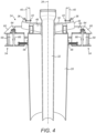
- FIGS 3 and 4 show the arrangement of the suction anchor assembly 24 in more detail, including the relationship between the suction anchor 28, the anchor brace 30 and the conductor 32.
- the anchor brace 30 comprises cross-members 46 that intersect centrally at a tubular support collar 48.
- the support collar 48 receives the conductor 32 telescopically.
- Opposed radially-extending arms of each cross-member 46 each support a respective one of the lifting points 36 and, inboard of the lifting point 36, one of the sockets 42 that receive one of the guide posts 40.
- Figure 3 also shows other features at the top of the suction anchor assembly 24, in particular: a vent hatch 50 that can also be used for contingency grouting; and a 'hot stab' connector 52 that enables suction pump operations with a high flow rate of, for example, 1500-2000 l/min.
- a vent hatch 50 that can also be used for contingency grouting
- a 'hot stab' connector 52 that enables suction pump operations with a high flow rate of, for example, 1500-2000 l/min.
- the suction anchor assembly 24 can also be fitted with survey equipment to capture and record accurate information as to heading, position and tilt of the suction anchor 28.
- an analogue manometer can give direct pressure readings inside the suction anchor 28.
- a clamping system comprising multiple individually-operable clamps 54 around the suction anchor 28 is also evident in Figures 3 and 4 .
- One of those clamps 54 is shown in detail in Figure 5 .
- clamps 54 there are four clamps 54 in this example, equi-angularly spaced around the central longitudinal axis 34 of the suction anchor assembly 24. Clamp shoes 56 of the clamps 54 act radially inwardly upon the tubular wall of the suction anchor 28 in mutually-opposed pairs.
- each clamp 54 is movable relative to a respective clamp box 58.
- the clamp boxes 58 are fixed to respective beam members 60 of the frame 12 at the base 14 of the SPU 10. Four such beam members 60 form a rectangle or square around the suction anchor 28.
- the suction anchor 28 is guided into a generally central position between the clamp boxes 58 by mutually-opposed, downwardly-converging guide formations 62 supported by the clamp boxes 58.
- the guide formations 62 define inwardly- and downwardly-inclined guide surfaces. The guide formations 62 thereby ensure that the suction anchor 28 is landed within tolerance for effective clamping, for example within a target box of ⁇ 0.2m.
- the lateral spacing between the opposed clamp boxes 58 exceeds the diameter of the tubular wall of the suction anchor 28. Consequently, there is a clearance between the clamp boxes 58 and the suction anchor 28. This clearance eases insertion of the suction anchor assembly 24 into the SPU 10.
- the clearance around the suction anchor 28 may vary between the clamps 54, depending upon how centrally the suction anchor 28 is positioned between them. Differential clearance between the clamp boxes 58 and the suction anchor 28 is dealt with by advancing the clamp shoes 56 in radially inward directions to different extents.
- Each clamp box 58 contains and supports a clamping mechanism that effects radial movement of the clamp shoes 56 in response to rotation of an upwardly-facing drive socket 64 that protrudes from the clamp box 58.
- the drive socket 64 is arranged to be engaged and turned by a standard Class 4 torque tool, which may conveniently be held by an ROV or diver in a routine manner.
- Rotation of the drive socket 64 turns an upright threaded drive screw 66 that is fixed to the drive socket 64 to turn on a common axis.
- the drive screw 66 is supported by bearings that are fixed to the clamp box 58.
- the drive screw 66 has a buttress thread for maximum strength.
- a nut 68 is engaged with the drive rod 66 but is held against rotation. The nut 68 is thereby driven up or down the drive rod 66 depending upon the direction of rotation of the drive rod 66.
- the nut 68 is pivotably engaged with a bell crank 70, which therefore turns about a pivot 72 in response to movement of the nut 68 along the rod 66.
- a first arm of the bell crank 70 receives the nut 68 in a slot, whose elongation allows for variation in radius between the nut 68 and the pivot 72 of the bell crank 70 as the nut 68 moves along the straight rod 66.
- a second arm of the bell crank 70 extends at about 90° to the first arm about the pivot 72.
- the second arm is pivotably engaged with a pin 74 near its free end opposite the pivot 72.
- the pin 74 is attached to a rod 76 that is constrained for straight radial movement with respect to the suction anchor 28.
- the clamp shoe 56 is fixed to a radially inner end of the rod 76.
- the second arm also receives the pin 74 in a slot.
- the elongation of the slot allows for variation in radius between the pin 74 and the pivot 72 as the pin 74 and the rod 76 follow their straight path.
- the bell crank 70 in this example is bifurcated into two parallel plates, one each side of the drive rod 66, nut 68, pin 74 and rod 76.
- the bell crank 70 converts movement of the nut 68 along the drive rod 66, caused by rotating the drive socket 64, into radial movement of the rod 76 and hence of the clamp shoe 56 that is fixed to the rod 76.
- the frame 12 of the SPU 10 can be fixed or locked to the suction anchor assembly 24 when the suction anchor 28 and conductor 32 have been embedded into the seabed 16 to a desired extent as shown in Figures 2 and 3 . Precise alignment between the suction anchor assembly 24 and the frame 12 of the SPU 10 is not necessary.
- Locking the frame 12 to the suction anchor assembly 24 allows the base 14 of the SPU 10 to interact beneficially with the suction anchor 28 to form a more effective foundation than either structure could provide in isolation.
- the base 14 of the SPU 10 spreads weight loads across a wider area of the seabed 16 and so relieves the suction anchor 28 from having to bear all of those loads. This means that the suction anchor 28 need not be as large and the integrated conductor 32 need not be as long as in prior art solutions.
- cross-members 46 of the anchor brace 30 may rest upon horizontal flanges of the surrounding beam members 60 at the base 14 of the SPU 10 when the suction anchor 28 is embedded fully into the seabed 16. This locates the suction anchor 28 axially against weight loads applied to the suction anchor 28. In this way, axial load is transferred from the anchor brace 30 into the base 14 of the SPU 10, which then distributes the load across the seabed 16. This allows the clamps 54 to be simplified as they need to provide only lateral location rather than axial location.
- the Christmas tree 78 can be installed either by a rig or a vessel.
- the Christmas tree 78 is lowered toward the SPU 10 with the guidance of parallel guide wires 80.
- the guide wires 80 extend upwardly from the guide posts 40 and extend through parallel tubular passageways in the Christmas tree 78.
- FIG. 7 shows the Christmas tree 78 now engaged with the guide posts 40.
- the Christmas tree 78 has been lowered beneath the opening 44 in the top 18 of the SPU 10 and is approaching engagement with the top end portion of the conductor 32, which protrudes upwardly above the anchor brace 30 of the suction anchor assembly 24.
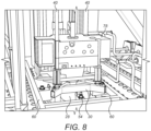
- Figure 8 shows the Christmas tree 78 now lowered fully into engagement with the top end portion of the conductor 32.
- the weight load of the Christmas tree 78 is now taken by the anchor brace 30 of the suction anchor assembly 24. That weight load is then distributed between the suction anchor 28 and the base 14 of the SPU 10 by virtue of the clamped connection between the suction anchor 28 and the frame 12 of the SPU 10.
- any misalignment between the suction anchor 28 and the SPU 10 is immaterial. Not only do the clamps 54 compensate for any such misalignment but also the Christmas tree 78 needs only to be aligned accurately with the suction anchor 28 rather than with the SPU 10. The necessary alignment between the Christmas tree 78 and the suction anchor 28 is assured by the guide posts 40 being attached to the anchor brace 30 that surmounts the suction anchor 28. So, the weight of the Christmas tree 78 is supported directly by the suction anchor 28 and only indirectly by the base 14 of the SPU 10 via the clamps 54.
- the conductor 32 will extend in length due to thermal expansion caused by the flow of hot fluids within and so will slide within the anchor brace 30 to move longitudinally relative to the surrounding suction anchor 28.
- the suction anchor whilst the suction anchor is shown as being installed from a vessel into the SPU after tow-out of the SPU, a different installation sequence may be possible.
- the suction anchor could be pre-installed and secured in the SPU, whereupon a crane of a vessel may be used to lower that assembly to the seabed.
- a suction anchor could be installed and used for drilling operations before the SPU is installed. The SPU can then be landed onto the guide base anchor.
Landscapes
- Engineering & Computer Science (AREA)
- Geology (AREA)
- Life Sciences & Earth Sciences (AREA)
- Mining & Mineral Resources (AREA)
- Environmental & Geological Engineering (AREA)
- Fluid Mechanics (AREA)
- Physics & Mathematics (AREA)
- General Life Sciences & Earth Sciences (AREA)
- Geochemistry & Mineralogy (AREA)
- Chemical & Material Sciences (AREA)
- Combustion & Propulsion (AREA)
- Mechanical Engineering (AREA)
- Ocean & Marine Engineering (AREA)
- Earth Drilling (AREA)
Claims (23)
- Verfahren zum Installieren eines Bohrleiters (32) für ein Unterwasserbohrloch, das Verfahren umfassend:Bereitstellen eines Saugankers (28), der angeordnet ist, um den Leiter (32) innerhalb zu stützen;Absenken des Saugankers (28) zu einer Unterwasserverarbeitungseinheit (10) hin an einer Stelle des Meeresbodens, wobei die Verarbeitungseinheit (10) einen Rahmen (12) aufweist, der eine Basis (14), die auf dem Meeresboden (16) liegt, und eine Oberseite (18) definiert, die von der Basis (14) beabstandet ist, um eine Ausrüstung (22) innerhalb der Verarbeitungseinheit (10) aufzunehmen;Absenken des Saugankers (28) in die Verarbeitungseinheit (10) durch die Oberseite (18) des Rahmens (12) hindurch;Einbetten des Saugankers (28) in den Meeresboden (16) unterhalb der Verarbeitungseinheit (10);Befestigen des Rahmens (12) an dem eingebetteten Sauganker (28), um eine strukturelle Einheit zu bilden, die den Leiter (32), den Sauganker (28) und den Rahmen (12) umfasst;Absenken zusätzlicher Ausrüstung (78) durch die Oberseite (18) des Rahmens (12) hindurch und auf den Leiter (32) hinauf, der durch den eingebetteten Sauganker (28) gestützt wird; undSchließen einer Öffnung (44) in dem Rahmen (12) oberhalb der zusätzlichen Ausrüstung (78) auf dem Leiter (32).
- Verfahren nach Anspruch 1, umfassend das Absenken und Einbetten des Saugankers (28) mit dem bereits innerhalb gestützten Leiter (32).
- Verfahren nach Anspruch 1 oder 2, ferner umfassend die vorläufigen Schritte von:Schleppen der Verarbeitungseinheit (10) zu einem Offshore-Installationsort; undAnlanden der Verarbeitungseinheit (10) auf den Meeresboden (16) hinauf an dem Installationsort.
- Verfahren nach einem der vorstehenden Ansprüche, umfassend ein Übertragen von Gewichtslast der zusätzlichen Ausrüstung (78) auf den eingebetteten Sauganker (28).
- Verfahren nach einem der vorstehenden Ansprüche, umfassend das Befestigen des Rahmens (12) an dem eingebetteten Sauganker (28), bevor die zusätzliche Ausrüstung (78) auf den Leiter (32) hinauf abgesenkt wird.
- Verfahren nach einem der vorstehenden Ansprüche, ferner umfassend:Verbinden eines oder mehrerer länglicher Führungselemente (40) mit dem eingebetteten Sauganker (28); undAbsenken der zusätzlichen Ausrüstung (78) entlang des oder jedes Führungselements (40).
- Verfahren nach Anspruch 6, umfassend das Absenken der zusätzlichen Ausrüstung (78) durch die Oberseite des Rahmens (12) hindurch entlang des oder jedes Führungselements (40), wobei sich das Führungselement (40) von dem eingebetteten Sauganker (28) nach oben erstreckt und über die Oberseite (18) des Rahmens (12) hinausragt.
- Verfahren nach einem der vorstehenden Ansprüche, umfassend ein Herstellen von Strom-, Steuer- und/oder Fluidverbindungen zwischen der zusätzlichen Ausrüstung (78) und der Ausrüstung (22) an Bord der Unterwasserverarbeitungseinheit (10), nachdem die zusätzliche Ausrüstung (78) auf den Leiter (32) hinauf abgesenkt wurde.
- Verfahren nach einem der vorstehenden Ansprüche, umfassend ein Bohren eines Bohrlochs durch den Leiter (32) hindurch vor dem Absenken der zusätzlichen Ausrüstung (78) auf den Leiter (32) hinauf.
- Verfahren nach einem der vorstehenden Ansprüche, umfassend das Befestigen des Rahmens (12) an dem eingebetteten Sauganker (28) durch Verlängern einer oder mehrerer Klammern (54) von dem Rahmen (12) in Klemmeingriff mit dem Sauganker (28).
- Verfahren nach einem der vorstehenden Ansprüche, umfassend das Anlanden des Saugankers (28) auf dem Meeresboden (16) innerhalb eines Anlandebereichs, der durch den Rahmen (12) definiert wird, bevor der Sauganker (28) in den Meeresboden (16) eingebettet wird.
- Verfahren nach Anspruch 11, umfassend ein Ausrichten des Saugankers (28) mit dem Anlandebereich durch Herstellen eines Ausrichtungskontakts zwischen dem Sauganker (28) und dem Rahmen (12), während der Sauganker (28) zu dem Meeresboden (16) hin abgesenkt wird.
- Verfahren nach Anspruch 11 oder 12, wobei der Anlandebereich breiter als der Sauganker (28) ist.
- Verfahren nach einem der vorstehenden Ansprüche, umfassend ein Aufsetzen einer Strebe (30), die sich von dem Sauganker (28) seitlich erstreckt, auf mindestens ein Element hinauf, das den Rahmen (12) definiert.
- Unterwasserverarbeitungseinheit (10), umfassend:einen Rahmen (12), der eine Basis (14) aufweist, die angeordnet ist, um auf dem Meeresboden (16) zu liegen; undAn-Bord-Ausrüstung (22), die auf der Basis (14) montiert ist;wobei die Basis (14) des Rahmens (12) einen Anlandebereich füreinen Sauganker (28) definiert und ein Befestigungssystem zum Befestigen des Saugankers (28) an dem Rahmen (12) trägt; unddadurch gekennzeichnet, dassder Rahmen (12) ferner eine Oberseite (18) umfasst, die von der Basis (14) beabstandet ist, wobei die Oberseite (18) des Rahmens (12) eine Öffnung (44) über dem Anlandebereich zum Aufnehmen des Saugankers (28) aufweist.
- Einheit (10) nach Anspruch 15, wobei das Befestigungssystem einen oder mehrere Klemmschuhe (56) umfasst, die aus dem Rahmen (12) zu dem Anlandebereich hin ausziehbar sind.
- Einheit (10) nach Anspruch 16, wobei das Befestigungssystem zwei oder mehr Klemmschuhe (56) umfasst, die aus dem Rahmen (12) in einander entgegengesetzten Richtungen ausziehbar sind.
- Einheit (10) nach Anspruch 17, wobei die Klemmschuhe (56) einzeln betätigbar und aus dem Rahmen (12) in unterschiedlichem Ausmaß relativ zueinander ausziehbar sind.
- Einheit (10) nach einem der Ansprüche 15 bis 18, ferner umfassend Führungsformationen (62), die geformt sind, um den Sauganker (28) in Ausrichtung mit dem Anlandebereich zu führen.
- Einheit (10) nach einem der Ansprüche 15 bis 19, wenn sie in Kombination mit mindestens einem Sauganker (28) auf dem Meeresboden (16) installiert ist, der innerhalb des Anlandebereichs in den Meeresboden (16) eingebettet ist und der durch das Befestigungssystem an dem Rahmen (12) befestigt ist, wobei der oder jeder Sauganker (28) einen rohrförmigen Bohrleiter (32) enthält und stützt.
- Einheit (10) nach Anspruch 20, wobei der oder jeder Sauganker (28) durch eine Ankerstrebe (30) überragt wird, die den Bohrleiter (32) mit dem Sauganker (28) verbindet.
- Einheit (10) nach Anspruch 20 oder 21, ferner umfassend mindestens ein sich nach oben erstreckendes längliches Führungselement (40), das mit dem oder jedem Sauganker (28) verbunden ist.
- Einheit (10) nach Anspruch 21, ferner umfassend eine zusätzliche Bohrlochkopfausrüstung, die auf dem Leiter (32) montiert ist, wobei die zusätzliche Bohrlochkopfausrüstung einen Blowout-Preventer oder einen Weihnachtbaum (78) umfasst.
Applications Claiming Priority (2)
| Application Number | Priority Date | Filing Date | Title |
|---|---|---|---|
| GB1800118.0A GB2569969B (en) | 2018-01-04 | 2018-01-04 | Integrating wells in towable subsea units |
| PCT/EP2019/050177 WO2019134976A1 (en) | 2018-01-04 | 2019-01-04 | Integrating wells in towable subsea units |
Publications (2)
| Publication Number | Publication Date |
|---|---|
| EP3735509A1 EP3735509A1 (de) | 2020-11-11 |
| EP3735509B1 true EP3735509B1 (de) | 2023-03-08 |
Family
ID=61190465
Family Applications (1)
| Application Number | Title | Priority Date | Filing Date |
|---|---|---|---|
| EP19701152.1A Active EP3735509B1 (de) | 2018-01-04 | 2019-01-04 | Integration von bohrlöchern in schleppbaren unterwassereinheiten |
Country Status (5)
| Country | Link |
|---|---|
| US (1) | US11346185B2 (de) |
| EP (1) | EP3735509B1 (de) |
| AU (1) | AU2019205596B2 (de) |
| GB (1) | GB2569969B (de) |
| WO (1) | WO2019134976A1 (de) |
Families Citing this family (10)
| Publication number | Priority date | Publication date | Assignee | Title |
|---|---|---|---|---|
| GB201622129D0 (en) * | 2016-12-23 | 2017-02-08 | Statoil Petroleum As | Subsea assembly modularisation |
| CN109826564B (zh) * | 2019-02-28 | 2023-11-07 | 中国地质大学(武汉) | 利用吸力锚连续下套管的海底浅层快速成直井装置及方法 |
| NO346267B1 (en) * | 2019-08-22 | 2022-05-16 | Fmc Kongsberg Subsea As | Subsea wellhead support system and associated method of installing a subsea wellhead support system |
| GB2586965A (en) * | 2019-08-29 | 2021-03-17 | Ge Oil & Gas Uk Ltd | Wellhead apparatus, assembly and method for supporting downhole tubing |
| NO20220645A1 (en) * | 2019-11-07 | 2022-06-03 | Aker Solutions As | Subsea wellhead systems and methods |
| GB2589076A (en) * | 2019-11-07 | 2021-05-26 | Aker Solutions As | Subsea wellhead systems and methods |
| US11840907B2 (en) * | 2019-11-13 | 2023-12-12 | Fmc Kongsberg Subsea As | Module, a system and a method for daisy chaining of satellite wells |
| CN114687700B (zh) * | 2022-03-28 | 2023-09-29 | 中国石油大学(华东) | 一种适合于深海浅层多气合采事故油气回收的吸力锚井口装置 |
| US12221860B2 (en) * | 2022-09-23 | 2025-02-11 | Chevron U.S.A. Inc. | Wellhead bracing system |
| CN118327507A (zh) * | 2024-05-13 | 2024-07-12 | 上海霞为石油设备技术服务有限公司 | 一种钻井井口装置 |
Family Cites Families (23)
| Publication number | Priority date | Publication date | Assignee | Title |
|---|---|---|---|---|
| US4784527A (en) | 1987-05-29 | 1988-11-15 | Conoco Inc. | Modular drilling template for drilling subsea wells |
| US4822212A (en) | 1987-10-28 | 1989-04-18 | Amoco Corporation | Subsea template and method for using the same |
| NL8800913A (nl) | 1988-04-08 | 1989-11-01 | Smit Offshore Contractors | Boor- en wininrichting voor olie en/of gas. |
| WO2003071092A1 (en) * | 2002-02-25 | 2003-08-28 | Subsea 7 | Protection structure and method for subsea oil recovery operations |
| SG157260A1 (en) | 2008-06-02 | 2009-12-29 | Keppel Offshore & Marine Techn | Offshore foundation system with integral elements for preloading and extracting |
| NO333136B1 (no) * | 2009-03-10 | 2013-03-11 | Aker Subsea As | Havbunnsbrønnramme med manifoldmottaksrom |
| NO329295B1 (no) * | 2009-04-02 | 2010-09-27 | Aker Subsea As | Brønnramme for beskyttelse av havbunns brønnutstyr, samt fremgangsmåte |
| NO331978B1 (no) | 2010-06-22 | 2012-05-14 | Neodrill As | Anordning og framgangsmåte for stabilisering av et brønnhode, samt anvendelse av et sugefundament til understøttelse av et brønnhode |
| US8950500B2 (en) | 2010-06-30 | 2015-02-10 | Fluor Technologies Corporation | Suction pile wellhead and cap closure system |
| NO334839B1 (no) | 2010-11-16 | 2014-06-16 | Aker Subsea As | Brønnhodesystem og låseanordning for utblåsningssikring |
| GB201208223D0 (en) | 2012-05-10 | 2012-06-20 | Geoprober Drilling Ltd | Drilling and lining subsea wellbores |
| GB2509165B (en) | 2012-12-21 | 2018-01-24 | Subsea 7 Norway As | Subsea processing of well fluids |
| GB201402176D0 (en) * | 2014-02-07 | 2014-03-26 | Enovate Systems Ltd | Wellbore installation apparatus and associated methods |
| GB2532754B (en) * | 2014-11-26 | 2020-11-25 | Equinor Energy As | Subsea equipment-protection apparatus |
| NO340357B1 (no) * | 2015-06-12 | 2017-04-10 | Neodrill As | System og framgangsmåte for etablering av flerbrønnsfundament omfattende en oppstillingsramme for sugefundamenter |
| AU2016314786A1 (en) * | 2015-09-04 | 2018-03-08 | Icon Engineering Pty Ltd | A fixed to bottom jacket system and method of installation for an offshore structure |
| NO341175B1 (en) * | 2015-10-29 | 2017-09-04 | Vetco Gray Scandinavia As | Subsea well template |
| GB2551236B (en) * | 2016-03-08 | 2020-05-13 | Equinor Energy As | Subsea wellhead assembly |
| GB2549458A (en) * | 2016-04-11 | 2017-10-25 | Statoil Petroleum As | Subsea foundation |
| GB201611695D0 (en) * | 2016-07-05 | 2016-08-17 | Statoil Petroleum As | Subsea wellhead installation and/or removal |
| NO344888B1 (en) * | 2016-12-22 | 2020-06-15 | Vetco Gray Scandinavia As | A flow base system for subsea wells |
| GB201622129D0 (en) * | 2016-12-23 | 2017-02-08 | Statoil Petroleum As | Subsea assembly modularisation |
| GB2566288B (en) * | 2017-09-07 | 2022-04-13 | Equinor Energy As | Marine suction anchor |
-
2018
- 2018-01-04 GB GB1800118.0A patent/GB2569969B/en active Active
-
2019
- 2019-01-04 AU AU2019205596A patent/AU2019205596B2/en active Active
- 2019-01-04 US US16/960,050 patent/US11346185B2/en active Active
- 2019-01-04 WO PCT/EP2019/050177 patent/WO2019134976A1/en not_active Ceased
- 2019-01-04 EP EP19701152.1A patent/EP3735509B1/de active Active
Also Published As
| Publication number | Publication date |
|---|---|
| GB2569969A (en) | 2019-07-10 |
| US11346185B2 (en) | 2022-05-31 |
| US20210054723A1 (en) | 2021-02-25 |
| BR112020013286A2 (pt) | 2020-12-01 |
| AU2019205596A1 (en) | 2020-07-16 |
| WO2019134976A1 (en) | 2019-07-11 |
| EP3735509A1 (de) | 2020-11-11 |
| GB2569969B (en) | 2020-04-08 |
| GB201800118D0 (en) | 2018-02-21 |
| AU2019205596B2 (en) | 2024-08-15 |
Similar Documents
| Publication | Publication Date | Title |
|---|---|---|
| US11346185B2 (en) | Integrating wells in towable subsea units | |
| US12560056B2 (en) | Tie-in of subsea pipeline | |
| US4194857A (en) | Subsea station | |
| KR101952355B1 (ko) | 부유식 해양 설비 및 웰 시추 방법 | |
| US4120362A (en) | Subsea station | |
| US20050152749A1 (en) | Telescopic guide pipe for offshore drilling | |
| US4437521A (en) | Subsea wellhead connection assembly and methods of installation | |
| US3701261A (en) | Apparatus for providing offshore installation | |
| NO312560B1 (no) | Intervensjonsmodul for en brönn | |
| US10753168B2 (en) | Subsea wellhead assembly | |
| WO2004018826A1 (en) | Subsea drilling module for use in drilling of oil and gas wells | |
| US4228857A (en) | Floating platform well production apparatus | |
| US11713654B2 (en) | Universal block platform | |
| NO344402B1 (en) | Integrating wells in towable subsea units | |
| US4442900A (en) | Subsea well completion system | |
| AU2020204672B2 (en) | Subsea connection of pipeline sections | |
| US3186487A (en) | Underwater well guide system | |
| US4693636A (en) | Pipeline pull-in method and apparatus | |
| US4279542A (en) | Subsea well flow lines tie-in using conductors | |
| GB2114189A (en) | A subsea wellhead connection assembly and a method of installing same | |
| BR112020013286B1 (pt) | Método de instalar um condutor de perfuração para um poço submarino e unidade de processamento submarina | |
| US3225826A (en) | Method and apparatus for working on submerged wells | |
| US20090223673A1 (en) | Offshore Riser Retrofitting Method and Apparatus | |
| GB2594009A (en) | Tie-in of subsea pipeline | |
| BR112019012283B1 (pt) | Método para instalação de uma junta de tubo principal em uma estrutura submarina, conjunto submarino, método para instalação de um coletor em uma estrutura submarina, método para ligar um conduto submarino a uma estrutura submarina e instalação submarina |
Legal Events
| Date | Code | Title | Description |
|---|---|---|---|
| STAA | Information on the status of an ep patent application or granted ep patent |
Free format text: STATUS: UNKNOWN |
|
| STAA | Information on the status of an ep patent application or granted ep patent |
Free format text: STATUS: THE INTERNATIONAL PUBLICATION HAS BEEN MADE |
|
| PUAI | Public reference made under article 153(3) epc to a published international application that has entered the european phase |
Free format text: ORIGINAL CODE: 0009012 |
|
| STAA | Information on the status of an ep patent application or granted ep patent |
Free format text: STATUS: REQUEST FOR EXAMINATION WAS MADE |
|
| 17P | Request for examination filed |
Effective date: 20200703 |
|
| AK | Designated contracting states |
Kind code of ref document: A1 Designated state(s): AL AT BE BG CH CY CZ DE DK EE ES FI FR GB GR HR HU IE IS IT LI LT LU LV MC MK MT NL NO PL PT RO RS SE SI SK SM TR |
|
| AX | Request for extension of the european patent |
Extension state: BA ME |
|
| DAV | Request for validation of the european patent (deleted) | ||
| DAX | Request for extension of the european patent (deleted) | ||
| GRAP | Despatch of communication of intention to grant a patent |
Free format text: ORIGINAL CODE: EPIDOSNIGR1 |
|
| STAA | Information on the status of an ep patent application or granted ep patent |
Free format text: STATUS: GRANT OF PATENT IS INTENDED |
|
| RIC1 | Information provided on ipc code assigned before grant |
Ipc: B63B 21/27 20060101ALN20221201BHEP Ipc: E21B 43/36 20060101ALI20221201BHEP Ipc: E21B 41/08 20060101AFI20221201BHEP |
|
| RIC1 | Information provided on ipc code assigned before grant |
Ipc: B63B 21/27 20060101ALN20221202BHEP Ipc: E21B 43/36 20060101ALI20221202BHEP Ipc: E21B 41/08 20060101AFI20221202BHEP |
|
| INTG | Intention to grant announced |
Effective date: 20221222 |
|
| GRAS | Grant fee paid |
Free format text: ORIGINAL CODE: EPIDOSNIGR3 |
|
| GRAA | (expected) grant |
Free format text: ORIGINAL CODE: 0009210 |
|
| STAA | Information on the status of an ep patent application or granted ep patent |
Free format text: STATUS: THE PATENT HAS BEEN GRANTED |
|
| AK | Designated contracting states |
Kind code of ref document: B1 Designated state(s): AL AT BE BG CH CY CZ DE DK EE ES FI FR GB GR HR HU IE IS IT LI LT LU LV MC MK MT NL NO PL PT RO RS SE SI SK SM TR |
|
| REG | Reference to a national code |
Ref country code: CH Ref legal event code: EP Ref country code: AT Ref legal event code: REF Ref document number: 1552681 Country of ref document: AT Kind code of ref document: T Effective date: 20230315 |
|
| REG | Reference to a national code |
Ref country code: IE Ref legal event code: FG4D |
|
| REG | Reference to a national code |
Ref country code: DE Ref legal event code: R096 Ref document number: 602019026126 Country of ref document: DE |
|
| REG | Reference to a national code |
Ref country code: LT Ref legal event code: MG9D |
|
| P01 | Opt-out of the competence of the unified patent court (upc) registered |
Effective date: 20230526 |
|
| REG | Reference to a national code |
Ref country code: NO Ref legal event code: T2 Effective date: 20230308 |
|
| REG | Reference to a national code |
Ref country code: NL Ref legal event code: MP Effective date: 20230308 |
|
| PG25 | Lapsed in a contracting state [announced via postgrant information from national office to epo] |
Ref country code: RS Free format text: LAPSE BECAUSE OF FAILURE TO SUBMIT A TRANSLATION OF THE DESCRIPTION OR TO PAY THE FEE WITHIN THE PRESCRIBED TIME-LIMIT Effective date: 20230308 Ref country code: LV Free format text: LAPSE BECAUSE OF FAILURE TO SUBMIT A TRANSLATION OF THE DESCRIPTION OR TO PAY THE FEE WITHIN THE PRESCRIBED TIME-LIMIT Effective date: 20230308 Ref country code: LT Free format text: LAPSE BECAUSE OF FAILURE TO SUBMIT A TRANSLATION OF THE DESCRIPTION OR TO PAY THE FEE WITHIN THE PRESCRIBED TIME-LIMIT Effective date: 20230308 Ref country code: HR Free format text: LAPSE BECAUSE OF FAILURE TO SUBMIT A TRANSLATION OF THE DESCRIPTION OR TO PAY THE FEE WITHIN THE PRESCRIBED TIME-LIMIT Effective date: 20230308 Ref country code: ES Free format text: LAPSE BECAUSE OF FAILURE TO SUBMIT A TRANSLATION OF THE DESCRIPTION OR TO PAY THE FEE WITHIN THE PRESCRIBED TIME-LIMIT Effective date: 20230308 |
|
| REG | Reference to a national code |
Ref country code: AT Ref legal event code: MK05 Ref document number: 1552681 Country of ref document: AT Kind code of ref document: T Effective date: 20230308 |
|
| PG25 | Lapsed in a contracting state [announced via postgrant information from national office to epo] |
Ref country code: SE Free format text: LAPSE BECAUSE OF FAILURE TO SUBMIT A TRANSLATION OF THE DESCRIPTION OR TO PAY THE FEE WITHIN THE PRESCRIBED TIME-LIMIT Effective date: 20230308 Ref country code: NL Free format text: LAPSE BECAUSE OF FAILURE TO SUBMIT A TRANSLATION OF THE DESCRIPTION OR TO PAY THE FEE WITHIN THE PRESCRIBED TIME-LIMIT Effective date: 20230308 Ref country code: GR Free format text: LAPSE BECAUSE OF FAILURE TO SUBMIT A TRANSLATION OF THE DESCRIPTION OR TO PAY THE FEE WITHIN THE PRESCRIBED TIME-LIMIT Effective date: 20230609 Ref country code: FI Free format text: LAPSE BECAUSE OF FAILURE TO SUBMIT A TRANSLATION OF THE DESCRIPTION OR TO PAY THE FEE WITHIN THE PRESCRIBED TIME-LIMIT Effective date: 20230308 |
|
| PG25 | Lapsed in a contracting state [announced via postgrant information from national office to epo] |
Ref country code: SM Free format text: LAPSE BECAUSE OF FAILURE TO SUBMIT A TRANSLATION OF THE DESCRIPTION OR TO PAY THE FEE WITHIN THE PRESCRIBED TIME-LIMIT Effective date: 20230308 Ref country code: RO Free format text: LAPSE BECAUSE OF FAILURE TO SUBMIT A TRANSLATION OF THE DESCRIPTION OR TO PAY THE FEE WITHIN THE PRESCRIBED TIME-LIMIT Effective date: 20230308 Ref country code: PT Free format text: LAPSE BECAUSE OF FAILURE TO SUBMIT A TRANSLATION OF THE DESCRIPTION OR TO PAY THE FEE WITHIN THE PRESCRIBED TIME-LIMIT Effective date: 20230710 Ref country code: EE Free format text: LAPSE BECAUSE OF FAILURE TO SUBMIT A TRANSLATION OF THE DESCRIPTION OR TO PAY THE FEE WITHIN THE PRESCRIBED TIME-LIMIT Effective date: 20230308 Ref country code: CZ Free format text: LAPSE BECAUSE OF FAILURE TO SUBMIT A TRANSLATION OF THE DESCRIPTION OR TO PAY THE FEE WITHIN THE PRESCRIBED TIME-LIMIT Effective date: 20230308 Ref country code: AT Free format text: LAPSE BECAUSE OF FAILURE TO SUBMIT A TRANSLATION OF THE DESCRIPTION OR TO PAY THE FEE WITHIN THE PRESCRIBED TIME-LIMIT Effective date: 20230308 |
|
| PG25 | Lapsed in a contracting state [announced via postgrant information from national office to epo] |
Ref country code: SK Free format text: LAPSE BECAUSE OF FAILURE TO SUBMIT A TRANSLATION OF THE DESCRIPTION OR TO PAY THE FEE WITHIN THE PRESCRIBED TIME-LIMIT Effective date: 20230308 Ref country code: PL Free format text: LAPSE BECAUSE OF FAILURE TO SUBMIT A TRANSLATION OF THE DESCRIPTION OR TO PAY THE FEE WITHIN THE PRESCRIBED TIME-LIMIT Effective date: 20230308 Ref country code: IS Free format text: LAPSE BECAUSE OF FAILURE TO SUBMIT A TRANSLATION OF THE DESCRIPTION OR TO PAY THE FEE WITHIN THE PRESCRIBED TIME-LIMIT Effective date: 20230708 |
|
| REG | Reference to a national code |
Ref country code: DE Ref legal event code: R097 Ref document number: 602019026126 Country of ref document: DE |
|
| PLBE | No opposition filed within time limit |
Free format text: ORIGINAL CODE: 0009261 |
|
| STAA | Information on the status of an ep patent application or granted ep patent |
Free format text: STATUS: NO OPPOSITION FILED WITHIN TIME LIMIT |
|
| PG25 | Lapsed in a contracting state [announced via postgrant information from national office to epo] |
Ref country code: SI Free format text: LAPSE BECAUSE OF FAILURE TO SUBMIT A TRANSLATION OF THE DESCRIPTION OR TO PAY THE FEE WITHIN THE PRESCRIBED TIME-LIMIT Effective date: 20230308 Ref country code: DK Free format text: LAPSE BECAUSE OF FAILURE TO SUBMIT A TRANSLATION OF THE DESCRIPTION OR TO PAY THE FEE WITHIN THE PRESCRIBED TIME-LIMIT Effective date: 20230308 |
|
| 26N | No opposition filed |
Effective date: 20231211 |
|
| PG25 | Lapsed in a contracting state [announced via postgrant information from national office to epo] |
Ref country code: IT Free format text: LAPSE BECAUSE OF FAILURE TO SUBMIT A TRANSLATION OF THE DESCRIPTION OR TO PAY THE FEE WITHIN THE PRESCRIBED TIME-LIMIT Effective date: 20230308 |
|
| REG | Reference to a national code |
Ref country code: DE Ref legal event code: R119 Ref document number: 602019026126 Country of ref document: DE |
|
| PG25 | Lapsed in a contracting state [announced via postgrant information from national office to epo] |
Ref country code: MC Free format text: LAPSE BECAUSE OF FAILURE TO SUBMIT A TRANSLATION OF THE DESCRIPTION OR TO PAY THE FEE WITHIN THE PRESCRIBED TIME-LIMIT Effective date: 20230308 |
|
| PG25 | Lapsed in a contracting state [announced via postgrant information from national office to epo] |
Ref country code: MC Free format text: LAPSE BECAUSE OF FAILURE TO SUBMIT A TRANSLATION OF THE DESCRIPTION OR TO PAY THE FEE WITHIN THE PRESCRIBED TIME-LIMIT Effective date: 20230308 |
|
| REG | Reference to a national code |
Ref country code: CH Ref legal event code: PL |
|
| PG25 | Lapsed in a contracting state [announced via postgrant information from national office to epo] |
Ref country code: LU Free format text: LAPSE BECAUSE OF NON-PAYMENT OF DUE FEES Effective date: 20240104 |
|
| PG25 | Lapsed in a contracting state [announced via postgrant information from national office to epo] |
Ref country code: LU Free format text: LAPSE BECAUSE OF NON-PAYMENT OF DUE FEES Effective date: 20240104 |
|
| PG25 | Lapsed in a contracting state [announced via postgrant information from national office to epo] |
Ref country code: DE Free format text: LAPSE BECAUSE OF NON-PAYMENT OF DUE FEES Effective date: 20240801 |
|
| PG25 | Lapsed in a contracting state [announced via postgrant information from national office to epo] |
Ref country code: BE Free format text: LAPSE BECAUSE OF NON-PAYMENT OF DUE FEES Effective date: 20240131 |
|
| PG25 | Lapsed in a contracting state [announced via postgrant information from national office to epo] |
Ref country code: CH Free format text: LAPSE BECAUSE OF NON-PAYMENT OF DUE FEES Effective date: 20240131 |
|
| PG25 | Lapsed in a contracting state [announced via postgrant information from national office to epo] |
Ref country code: DE Free format text: LAPSE BECAUSE OF NON-PAYMENT OF DUE FEES Effective date: 20240801 Ref country code: CH Free format text: LAPSE BECAUSE OF NON-PAYMENT OF DUE FEES Effective date: 20240131 Ref country code: BE Free format text: LAPSE BECAUSE OF NON-PAYMENT OF DUE FEES Effective date: 20240131 |
|
| REG | Reference to a national code |
Ref country code: BE Ref legal event code: MM Effective date: 20240131 |
|
| PG25 | Lapsed in a contracting state [announced via postgrant information from national office to epo] |
Ref country code: BG Free format text: LAPSE BECAUSE OF FAILURE TO SUBMIT A TRANSLATION OF THE DESCRIPTION OR TO PAY THE FEE WITHIN THE PRESCRIBED TIME-LIMIT Effective date: 20230308 |
|
| PG25 | Lapsed in a contracting state [announced via postgrant information from national office to epo] |
Ref country code: BG Free format text: LAPSE BECAUSE OF FAILURE TO SUBMIT A TRANSLATION OF THE DESCRIPTION OR TO PAY THE FEE WITHIN THE PRESCRIBED TIME-LIMIT Effective date: 20230308 |
|
| PG25 | Lapsed in a contracting state [announced via postgrant information from national office to epo] |
Ref country code: IE Free format text: LAPSE BECAUSE OF NON-PAYMENT OF DUE FEES Effective date: 20240104 |
|
| PG25 | Lapsed in a contracting state [announced via postgrant information from national office to epo] |
Ref country code: IE Free format text: LAPSE BECAUSE OF NON-PAYMENT OF DUE FEES Effective date: 20240104 |
|
| PG25 | Lapsed in a contracting state [announced via postgrant information from national office to epo] |
Ref country code: CY Free format text: LAPSE BECAUSE OF FAILURE TO SUBMIT A TRANSLATION OF THE DESCRIPTION OR TO PAY THE FEE WITHIN THE PRESCRIBED TIME-LIMIT; INVALID AB INITIO Effective date: 20190104 |
|
| PG25 | Lapsed in a contracting state [announced via postgrant information from national office to epo] |
Ref country code: HU Free format text: LAPSE BECAUSE OF FAILURE TO SUBMIT A TRANSLATION OF THE DESCRIPTION OR TO PAY THE FEE WITHIN THE PRESCRIBED TIME-LIMIT; INVALID AB INITIO Effective date: 20190104 |
|
| PG25 | Lapsed in a contracting state [announced via postgrant information from national office to epo] |
Ref country code: TR Free format text: LAPSE BECAUSE OF FAILURE TO SUBMIT A TRANSLATION OF THE DESCRIPTION OR TO PAY THE FEE WITHIN THE PRESCRIBED TIME-LIMIT Effective date: 20230308 |
|
| PGFP | Annual fee paid to national office [announced via postgrant information from national office to epo] |
Ref country code: GB Payment date: 20260127 Year of fee payment: 8 |
|
| PGFP | Annual fee paid to national office [announced via postgrant information from national office to epo] |
Ref country code: NO Payment date: 20260120 Year of fee payment: 8 |
|
| PGFP | Annual fee paid to national office [announced via postgrant information from national office to epo] |
Ref country code: FR Payment date: 20260121 Year of fee payment: 8 |