EP3735528B1 - Feuerwiderstandsvorrichtung, die dazu bestimmt ist, zwischen einem stromaufwärtigen ende einer flugzeugturbinentriebwerksaufhängungsstruktur und einer verkleidung des turbinentriebwerks, die einen zwischenströmungsraum begrenzt, angeordnet zu werden - Google Patents
Feuerwiderstandsvorrichtung, die dazu bestimmt ist, zwischen einem stromaufwärtigen ende einer flugzeugturbinentriebwerksaufhängungsstruktur und einer verkleidung des turbinentriebwerks, die einen zwischenströmungsraum begrenzt, angeordnet zu werden Download PDFInfo
- Publication number
- EP3735528B1 EP3735528B1 EP19711153.7A EP19711153A EP3735528B1 EP 3735528 B1 EP3735528 B1 EP 3735528B1 EP 19711153 A EP19711153 A EP 19711153A EP 3735528 B1 EP3735528 B1 EP 3735528B1
- Authority
- EP
- European Patent Office
- Prior art keywords
- contact
- turbine engine
- upstream end
- mounting structure
- support portion
- Prior art date
- Legal status (The legal status is an assumption and is not a legal conclusion. Google has not performed a legal analysis and makes no representation as to the accuracy of the status listed.)
- Active
Links
Images




Classifications
-
- F—MECHANICAL ENGINEERING; LIGHTING; HEATING; WEAPONS; BLASTING
- F02—COMBUSTION ENGINES; HOT-GAS OR COMBUSTION-PRODUCT ENGINE PLANTS
- F02C—GAS-TURBINE PLANTS; AIR INTAKES FOR JET-PROPULSION PLANTS; CONTROLLING FUEL SUPPLY IN AIR-BREATHING JET-PROPULSION PLANTS
- F02C7/00—Features, components parts, details or accessories, not provided for in, or of interest apart form groups F02C1/00 - F02C6/00; Air intakes for jet-propulsion plants
- F02C7/24—Heat or noise insulation
- F02C7/25—Fire protection or prevention
-
- F—MECHANICAL ENGINEERING; LIGHTING; HEATING; WEAPONS; BLASTING
- F01—MACHINES OR ENGINES IN GENERAL; ENGINE PLANTS IN GENERAL; STEAM ENGINES
- F01D—NON-POSITIVE DISPLACEMENT MACHINES OR ENGINES, e.g. STEAM TURBINES
- F01D25/00—Component parts, details, or accessories, not provided for in, or of interest apart from, other groups
- F01D25/16—Arrangement of bearings; Supporting or mounting bearings in casings
- F01D25/162—Bearing supports
-
- F—MECHANICAL ENGINEERING; LIGHTING; HEATING; WEAPONS; BLASTING
- F01—MACHINES OR ENGINES IN GENERAL; ENGINE PLANTS IN GENERAL; STEAM ENGINES
- F01D—NON-POSITIVE DISPLACEMENT MACHINES OR ENGINES, e.g. STEAM TURBINES
- F01D9/00—Stators
- F01D9/06—Fluid supply conduits to nozzles or the like
- F01D9/065—Fluid supply or removal conduits traversing the working fluid flow, e.g. for lubrication-, cooling-, or sealing fluids
-
- F—MECHANICAL ENGINEERING; LIGHTING; HEATING; WEAPONS; BLASTING
- F02—COMBUSTION ENGINES; HOT-GAS OR COMBUSTION-PRODUCT ENGINE PLANTS
- F02C—GAS-TURBINE PLANTS; AIR INTAKES FOR JET-PROPULSION PLANTS; CONTROLLING FUEL SUPPLY IN AIR-BREATHING JET-PROPULSION PLANTS
- F02C7/00—Features, components parts, details or accessories, not provided for in, or of interest apart form groups F02C1/00 - F02C6/00; Air intakes for jet-propulsion plants
- F02C7/28—Arrangement of seals
-
- F—MECHANICAL ENGINEERING; LIGHTING; HEATING; WEAPONS; BLASTING
- F02—COMBUSTION ENGINES; HOT-GAS OR COMBUSTION-PRODUCT ENGINE PLANTS
- F02K—JET-PROPULSION PLANTS
- F02K1/00—Plants characterised by the form or arrangement of the jet pipe or nozzle; Jet pipes or nozzles peculiar thereto
- F02K1/78—Other construction of jet pipes
- F02K1/80—Couplings or connections
-
- F—MECHANICAL ENGINEERING; LIGHTING; HEATING; WEAPONS; BLASTING
- F02—COMBUSTION ENGINES; HOT-GAS OR COMBUSTION-PRODUCT ENGINE PLANTS
- F02K—JET-PROPULSION PLANTS
- F02K1/00—Plants characterised by the form or arrangement of the jet pipe or nozzle; Jet pipes or nozzles peculiar thereto
- F02K1/78—Other construction of jet pipes
- F02K1/80—Couplings or connections
- F02K1/805—Sealing devices therefor, e.g. for movable parts of jet pipes or nozzle flaps
-
- F—MECHANICAL ENGINEERING; LIGHTING; HEATING; WEAPONS; BLASTING
- F02—COMBUSTION ENGINES; HOT-GAS OR COMBUSTION-PRODUCT ENGINE PLANTS
- F02K—JET-PROPULSION PLANTS
- F02K3/00—Plants including a gas turbine driving a compressor or a ducted fan
- F02K3/02—Plants including a gas turbine driving a compressor or a ducted fan in which part of the working fluid by-passes the turbine and combustion chamber
- F02K3/04—Plants including a gas turbine driving a compressor or a ducted fan in which part of the working fluid by-passes the turbine and combustion chamber the plant including ducted fans, i.e. fans with high volume, low pressure outputs, for augmenting the jet thrust, e.g. of double-flow type
- F02K3/06—Plants including a gas turbine driving a compressor or a ducted fan in which part of the working fluid by-passes the turbine and combustion chamber the plant including ducted fans, i.e. fans with high volume, low pressure outputs, for augmenting the jet thrust, e.g. of double-flow type with front fan
-
- F—MECHANICAL ENGINEERING; LIGHTING; HEATING; WEAPONS; BLASTING
- F05—INDEXING SCHEMES RELATING TO ENGINES OR PUMPS IN VARIOUS SUBCLASSES OF CLASSES F01-F04
- F05D—INDEXING SCHEME FOR ASPECTS RELATING TO NON-POSITIVE-DISPLACEMENT MACHINES OR ENGINES, GAS-TURBINES OR JET-PROPULSION PLANTS
- F05D2220/00—Application
- F05D2220/30—Application in turbines
- F05D2220/32—Application in turbines in gas turbines
- F05D2220/323—Application in turbines in gas turbines for aircraft propulsion, e.g. jet engines
-
- F—MECHANICAL ENGINEERING; LIGHTING; HEATING; WEAPONS; BLASTING
- F05—INDEXING SCHEMES RELATING TO ENGINES OR PUMPS IN VARIOUS SUBCLASSES OF CLASSES F01-F04
- F05D—INDEXING SCHEME FOR ASPECTS RELATING TO NON-POSITIVE-DISPLACEMENT MACHINES OR ENGINES, GAS-TURBINES OR JET-PROPULSION PLANTS
- F05D2230/00—Manufacture
- F05D2230/60—Assembly methods
-
- F—MECHANICAL ENGINEERING; LIGHTING; HEATING; WEAPONS; BLASTING
- F05—INDEXING SCHEMES RELATING TO ENGINES OR PUMPS IN VARIOUS SUBCLASSES OF CLASSES F01-F04
- F05D—INDEXING SCHEME FOR ASPECTS RELATING TO NON-POSITIVE-DISPLACEMENT MACHINES OR ENGINES, GAS-TURBINES OR JET-PROPULSION PLANTS
- F05D2240/00—Components
- F05D2240/55—Seals
-
- F—MECHANICAL ENGINEERING; LIGHTING; HEATING; WEAPONS; BLASTING
- F05—INDEXING SCHEMES RELATING TO ENGINES OR PUMPS IN VARIOUS SUBCLASSES OF CLASSES F01-F04
- F05D—INDEXING SCHEME FOR ASPECTS RELATING TO NON-POSITIVE-DISPLACEMENT MACHINES OR ENGINES, GAS-TURBINES OR JET-PROPULSION PLANTS
- F05D2260/00—Function
- F05D2260/30—Retaining components in desired mutual position
-
- Y—GENERAL TAGGING OF NEW TECHNOLOGICAL DEVELOPMENTS; GENERAL TAGGING OF CROSS-SECTIONAL TECHNOLOGIES SPANNING OVER SEVERAL SECTIONS OF THE IPC; TECHNICAL SUBJECTS COVERED BY FORMER USPC CROSS-REFERENCE ART COLLECTIONS [XRACs] AND DIGESTS
- Y02—TECHNOLOGIES OR APPLICATIONS FOR MITIGATION OR ADAPTATION AGAINST CLIMATE CHANGE
- Y02T—CLIMATE CHANGE MITIGATION TECHNOLOGIES RELATED TO TRANSPORTATION
- Y02T50/00—Aeronautics or air transport
- Y02T50/60—Efficient propulsion technologies, e.g. for aircraft
Definitions
- the invention relates to the fire resistance function between an inter-vein compartment of a bypass aircraft turbomachine, and a zone upstream of the attachment pylon of this turbomachine. It aims in particular to prevent a fire initiated in the inter-vein compartment from spreading to the area upstream of the attachment mast.
- the invention applies to any type of turbofan engine, and in particular to a turbojet engine.
- a dual-flow aircraft turbomachine there is usually provided, downstream of the fan, one or more arms passing radially through the secondary stream.
- This arm is typically arranged so as to connect a fan compartment located around the outer shroud of an intermediate casing, to an inter-vein compartment.
- These two compartments conventionally house equipment and services, while the arm interposed between them allows the passage of various elements such as electric cables and/or fluid pipes.
- the document FR 2 920 215 discloses a prior art turbofan aircraft turbine engine.
- connection cowlings which are located respectively laterally on either side of an upstream end of the attachment pylon.
- the attachment pylon which is used to fix the turbine engine on a wing element of the aircraft, can indeed have an upstream end close to the junction between the arm crossing the secondary stream, and the upstream ring of the inter compartment -vein. This raises the problem of the fire protection function, since it is sought to avoid the propagation of a possible flame declaring itself in the inter-vein compartment, in particular to prevent this flame from reaching the upstream zone of the mast. nearby.
- the invention first of all relates to a fire resistance device according to the characteristics of claim 1.
- the invention thus proves advantageous in that it provides a fire resistance device which proves to be efficient, which fits perfectly into its environment, and whose preferential one-piece character makes its manufacture particularly easy and inexpensive, in particular with regard to the tools required.
- the one-piece appearance is made possible by the simple geometry of the device according to the invention, in particular by the use of contact lips. These do not, moreover, require the use of an insert during the manufacture of the device, as opposed, for example, to the implementation of hollow contact zones, called bead or bead contact zones.
- a lip usually turns out to be easily deformable, so that it is not necessary to subject it to a specific prestressing operation after its assembly. The deformation required to guarantee its function as a fire barrier can simply result from the support of a surrounding element, such as for example the support of a movable nacelle cowl seal intended to crash into the zone.
- the fire resistance device makes it possible to form two distinct and substantially contiguous physical barriers.
- One is provided to stop any fire in the inter-vein compartment so that it does not spread circumferentially towards the side face of the mast nor radially towards an upstream end face of the latter, and the other is planned so that this possible fire does not propagate axially downstream, along this same side face of the mast.
- the invention preferably provides at least one of the following optional technical characteristics, taken individually or in combination.
- said second line is straight, and preferably substantially orthogonal to a first substantially planar contact surface in which the first curved line is inscribed. Nevertheless, other line shapes and other inclinations can be retained depending on the bearing surfaces to be contacted, without departing from the scope of the invention.
- the first contact lip defines, between a base thereof and the first contact end, a first general lip direction inclined with respect to the normal to the first contact surface
- the second lip of contact defines, between a base of the latter and the second contact end, a second general direction of the lip inclined with respect to the normal to a bearing surface of this second lip. Thanks to these inclinations, the crushing of the lips is facilitated, in particular during the relative movements encountered in flight between the turbomachine and its mast. This principle is also applicable when the first and second contact members take a shape other than that of a lip.
- the first support portion has the general shape of an angle iron.
- the device also comprises a fixing portion extending from the first support portion, said fixing portion preferably being traversed by holes for passage of fixing elements.
- the second support portion carries, opposite the second contact member and its second junction zone, elongated elements of fixation. These elongated fixing elements can then easily cooperate with the connection cowling, for a better hold on the latter.
- the device is formed by the superposition of at least one layer of elastomeric material, preferably silicone elastomer, and at least one fibrous layer, preferably ceramic, glass or meta-aramid (poly(m- phenyleneisophthalamide)).
- elastomeric material preferably silicone elastomer
- fibrous layer preferably ceramic, glass or meta-aramid (poly(m- phenyleneisophthalamide)
- a layer of ceramic fabric proves to be particularly effective for the fire resistance function
- a layer of glass fibers makes it possible to stiffen the stack, and to limit the creep of silicone elastomer in the plane orthogonal to the direction of superposition of the layers, in the event of mechanical stress along this latter direction.
- meta-aramid fibers also allows such stiffening.
- one or more fibrous layers extend over the entire length of the first contact member, just as one or more fibrous layers extend over the entire length of the second contact member.
- the thruster assembly also comprises, associated with each connection cowling, a fire resistance device as described previously, interposed between the upstream end of the attachment pylon and the connection cowling to which the device.
- the first contact end of the first contact member bears against the peripheral bearing surface of the upstream end of the attachment pylon, and the second contact end of the second contact member bears against the corresponding side face. from the upstream end of the attachment mast.
- the first curved line is part of a first substantially planar contact surface, and substantially parallel to the transverse direction as well as to a longitudinal direction of the assembly, and the second line defined by the second contact member is a straight line extending substantially parallel to a vertical direction of the assembly.
- the second contact member is preferably constrained between the lateral face of the upstream end of the attachment pylon, and a nacelle moving cowl seal.
- the invention also relates to a method of manufacturing a fire resistance device as described above, implemented so that the device is made in one piece, that is to say in one piece. , and preferably by molding.
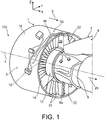
- This assembly 100 comprises a dual-flow turbine engine 1 for an aircraft, as well as an attachment strut 9 for this turbine engine on a wing element of the aircraft (not shown).
- the thruster assembly 100 has a longitudinal direction X, also corresponding to the longitudinal direction of the turbine engine 1 and to that of the mast 9.
- the assembly 100 also has a transverse direction Y, as well as a vertical direction Z, corresponding to the height direction.
- the three directions X, Y and Z are orthogonal to each other and form a direct trihedron.
- the mast 9 makes it possible to suspend the turbine engine 1 under a wing of the aircraft.
- This mast comprises a structural part intended to take up the forces coming from the turbomachine, this part usually being called the primary structure or the rigid structure. It generally takes the form of a box, of which only one upstream end 7 is represented on the figure 1 .
- the mast is also equipped with secondary structures (not shown) in the form of aerodynamic fairings.
- the turbomachine 1 is a dual-spool turbofan engine.
- the turbojet engine 1 has a central longitudinal axis 2 parallel to the direction X, and around which its various components extend. It comprises, from upstream to downstream along a main direction 5 of gas flow through this turbomachine, a fan 3 then a gas generator conventionally formed by compressors, a combustion chamber and turbines. These elements of the gas generator are surrounded by a central casing 6, also referred to as the “core” casing, which delimits radially inwardly an inter-vein compartment 8a. This compartment 8a is also delimited radially outwards by one or more covers, including an upstream ring 10 which is the only one represented on the figure 1 .
- the upstream ring 10 is arranged in the downstream continuity of a hub 12 of an intermediate casing 14 of the turbojet engine.
- the crankcase intermediate 14 also comprises an outer shroud 16 located in the downstream continuity of a fan casing 18. It also comprises outlet guide vanes 20, arranged downstream of the fan blades and connecting the hub 12 to the outer shroud 16.
- This compartment 8b is also delimited radially outwards by one or more cowlings (not shown), forming part of a nacelle of the turbojet engine.
- this compartment 8b houses equipment and utilities, as is widely known from the prior art.
- One or more arms 22 are provided to connect the two compartments 8a, 8b. These are for example two arms 22 which equip the turbojet engine, respectively arranged in time positions called at 12 o'clock and at 6 o'clock. These arms 22 are hollow, and they allow for example to circulate electric cables, and / or fluidic pipes. More specifically, these arms connect a downstream part of the outer shroud 16 to the upstream ring 10. To do this, they cross a secondary stream 26 of the turbojet engine, this stream being partly delimited outwardly by the shroud 16 thus only by cowlings (not shown) disposed downstream thereof, and partly delimited inwardly by the upstream ring 10 of the inter-vein compartment 8a.
- the secondary vein 26 is added to a primary vein 28, which passes through the gas generator in a conventional manner.
- connection covers 30 ensuring the aerodynamic junction between the arm 22 and the upstream ring 10. The latter is thus not completely closed over 360° , but it has an angular opening centered on the 12 o'clock position, at which point the two coupling cowls 30 provide the junction with the radially inner end of the arm 22.
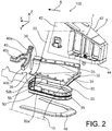
- connection cowling 30 has an upstream end 32 which is intended to be located in the downstream continuity of the hub of the intermediate casing. Its upper end 33 is connected to a wall of the arm 22, while its circumferential end 35 is connected to a circumferential end of the upstream ring 10. Finally, its downstream end 38 forms a housing 39 of the angular groove sector type, housing a nacelle seal 40 which is preferably carried by a movable nacelle cowl (not shown in the figures 2 to 5 ).
- This joint 40 also called three-legged joint or tripod joint, in fact comprises a node from which extends a first portion of joint 40a crushing in the housing 39 then on the upstream ring 10, a second portion of seal 40b crashing into housing 39 then onto arm 22, and a third portion of seal 40c crashing into a side face 42 of the mast.
- Each branch of the joint 40 is of the tubular, beaded or beaded type.
- the joint 40 thus adopts the position represented on the picture 3 after the closure of the mobile nacelle cowl on which it is installed, cowl which then has an outer surface arranged in the downstream continuity of an outer surface 34 of the coupling cowling 30.
- the upstream end 7 of the mast 9 has a base 44, from which extend in particular the two side faces 42.
- the base 44 is integral with a peripheral bearing surface 46 in the general shape of a U, following the contour of this base 44. It is substantially flat, parallel to the X and Y directions. Its function lies essentially in establishing a fire barrier between the inter-vein compartment 8a, and the upstream end 7 of the mast.
- the assembly 100 comprises a fire resistance device 50 specific to the invention, associated with each connection cowling 30.
- the fire resistance device 50 is thus interposed between the upstream end 7 of the mast, and its associated connection cowling 30 to which this same device is fixed.
- the device 50 has a first contact member, here a first contact lip 52a, as well as a second contact member, here a second contact lip 52b, the first lip 52a resting against a radially outer surface of the peripheral bearing surface 46, over a half-portion thereof.
- This first contact lip 52a allows a fire that breaks out in the inter-vein compartment 8a not to spread circumferentially towards the side face 42 of the mast, nor radially outwards towards an upstream end face. of this same mast.
- the second contact lip 52b is based on the side face 42 of the mast, downstream of the two portions 40a, 40b of the nacelle seal 40. It is designed to stop any fire in the inter-vein compartment 8a so that it does not propagate axially downstream, along the side face 42 of the mast.
- the device 50 offers a clever and effective solution for imparting the anti-fire function, despite the relative movements liable to be observed between the turbojet engine and the mast, during the various phases of flight of the aircraft.
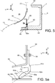
- the figures 5 and 5a at 5c show different levels of compression of the first lip 52a, depending on the relative position between the turbojet engine and the mast.
- the device 50 is fixed using fixing elements 54 of the bolt or rivet type. These elements 54 in fact pass through a fixing portion 56 of the device 50, as well as a first support 58 of the connection cowling 30, located radially inwards between the latter and the peripheral bearing surface 46.
- the first support 58 has a shape general of U open laterally outwards.
- the device 50 also comprises a first connection portion 60a in the general shape of an angle iron, from which the attachment portion 56 extends in the direction Z, upwards.
- the lower branch of the angle iron 60a is extended by a first junction zone 62a which ensures the transition with the first contact lip 52a.
- This junction zone 62a possibly of reduced thickness, serves as a hinge for the lip 52a which preferentially remains straight and not or only slightly deformed in bending, whatever the level of compression undergone.
- the shape of this lip 52a is similar to a convex blade at its radially outer surface, opposite to its radially inner surface opposite the peripheral bearing surface 46 and having a substantially planar shape.
- the figure 5 and 5b show a nominal compression level of the device 50 in the Z direction, with an angle of inclination A1 between the normal 64a to the bearing surface of the peripheral bearing surface 46, and a first general direction of lip 66a defined between a base 68a of this first lip 52a, and a first contact end 70a thereof.
- the angle A2 between the normal 64a and the general direction of the lip 66a is lower, while when the level of compression increases as shown schematically in the figure 5c , the angle A3 between the normal 64a and the general direction of the lip 66a is higher.
- the latter can reach 90°. In all cases, it is the level of deformation of the first junction zone 62a which causes the lip 52a to adopt different angles with respect to the normal 64a, it being specified again that this lip 52 remains rigid, and little or not deformed in bending.
- the design of the fire resistance device 50 makes it possible to maintain contact between the first lip 52a and the peripheral bearing surface 46, regardless of the relative movements observed between the turbojet engine and the mast, and this in each of the three directions X, Y and Z.
- first contact lip 52a it makes it possible to establish a first sealing line on the peripheral bearing surface 46, as shown in the figure 6 .
- This is a first curved line 72a, following the profile of the half-portion of the bearing surface 46 associated with the lip 52a.
- the first contact end of this lip 52a extends along this first line curve 72a, generally L-shaped.
- One of the special features of the invention resides in the fact that the device 50 therefore incorporates the aforementioned second lip, the function of which is to establish a second sealing line 72b on the face side 42 of the mast 9.
- This second line is preferably straight, substantially parallel to the direction Z.
- the two lines 72a, 72b meet at a radially internal downstream end of the device 50.
- the two lips can be directly contiguous, they can alternatively be connected by the first support portion 60a, as shown in the figures 7 to 12 showing device 50 in more detail.
- the first contact lip 52a is shown first, its first contact end extending along the first curved sealing line 72a, the first support portion 60a in the form of an angle iron, and the first junction zone 62a. All of the elements 52a, 60a, 62a extend the full length of the fire resistance device 50, parallel to the first curved line 72a.
- This is part of a first substantially planar contact surface S1, which corresponds to the radially outer surface of the peripheral bearing surface 46.
- This surface S1 can be strictly planar, or have one or more levels of very low height, for example not exceeding a few millimeters.
- the surface S1 thus preferably corresponds to an XY plane of the thruster assembly 100.
- the first curved line 72a which is inscribed in this XY plane and along which the first lip extends 52a, has a general L-shape, the angle between the base of the L and the branch of the L can be rounded, and the free end of the branch can also be rounded.
- the fixing fixing portion 56 extends upwards in the direction Z, in the form of a strip pierced with passage holes 76 intended to be traversed by the bolts 54 cited above.
- This first attachment portion 60a extends along the base of the L, as well as over most of its branch.
- the passage holes 76 can be reinforced by inserts 77 added later to the device 50, as shown on the figure 12 .
- a second support portion 60b also extends upwards substantially in the direction Z. More specifically, this second support portion 60b has a thickness upper which extends upwards from an outer radial end of the first support portion 60a, that is to say from the upper branch of the angle iron.
- a rib 80 is interposed between the fixing portion 56, and the second block-shaped support portion 60b. This rib 80 also extends upwards substantially along the direction Z, parallel to the fixing portion 56 from which it can be separated, along the direction of the first curved line 72a.
- the rib 80 has an intermediate thickness between that of the attachment portion 56, and that of the second support portion 60b.
- the second support portion 60b has the function of carrying the second lip 52b, via a second junction zone 62b interposed between them.
- the second junction zone 62b has a reduced thickness, and serves as a hinge for the second lip 52b which preferentially remains straight and not or only slightly deformed in bending, whatever the level of compression undergone.
- the second junction zone 62b extends not only from the second support portion 60b substantially in the direction X, downstream, but also from the upper branch of the angle iron 60a substantially in the direction Z, towards the top. At its downstream end, it carries the lip 52b whose second contact end 70b extends along the second preferably straight line 72b, and preferably substantially orthogonal to the first contact surface S1.
- the second straight line 72b preferably extends substantially along the direction Z, so that the lip 52b contacts the associated side face of the mast.
- the outer radial end of the assembly formed by the elements 60b, 62b and 52b is bevelled, as best seen on the figure 10 .
- the second contact lip 52b has an increasing thickness going from its base 68b referenced on the figure 11 , to the second contact end 70a. Consequently, the latter may have a surface character, for example in the form of a vertical band.
- an angle of inclination B0 can be observed between a normal 64b to the side face of the mast (not shown), and a second general direction of the lip 66b defined between a base 68b, and the second contact end 70b of the lip 52b .
- this angle B1 then depends on the level of compression of the resistance device 50, which itself depends on the amplitude of the relative movements between the turbojet engine and the mast.
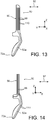
- the figures 15 and 16 also show that the third portion 40c of the gasket 40 is constrained in the Y direction, implying that its tubular sealing part is deformed between the nacelle cowl 82 and the lip 52b.
- the tubular part which has a section of substantially circular shape in the unconstrained state, flattens under stress, adopting a shape for example elliptical or similar.
- the second support portion 60b of the device 50 is received in a second support 86, provided on the coupling cover 30, at its downstream end 38 forming the seal housing 39.
- the second support 86 which is best seen on the figure 6 , has holes 88 intended to receive elongated fixing elements 90 carried by the support portion 60b, on the side opposite that where the lip 52b and its second junction zone 62b are located.
- These elongated elements 90 referenced in particular on the figure 10 , are made from a single room with the device 50, or reported on the latter. They are for example formed by rods whose end is intended to be crushed on the opposite surface of the second support 86 which they pass through.
- Another feature of the invention resides in the preferably one-piece manufacture of the fire resistance device 50.
- all of the aforementioned elements of the device 50 are made in one piece, preferably by compression molding.
- the elongated fixing elements 90 are optionally integrated into this piece in one piece, while the inserts 77 are considered as external add-on elements to the device, since they form part of its fixing means on the connection cowling 30.
- the device 50 may be a simple elastomer block, but the latter is preferably combined with one or more layers of various functionalities.
- the device 50 is formed by the superposition, in the direction of the thickness 92 of the latter, of layers of elastomeric material 99 and preferably of silicone elastomeric material, and fibrous functional layers 110.
- layers of elastomeric material 99 and preferably of silicone elastomeric material, and fibrous functional layers 110 may be act of layers of glass cloth, which reinforce the rigidity of the device.
- specific fire resistance layers can be provided, for example made of ceramic fiber.
- these are arranged in the zones of the device most exposed to the flame.
- the silicone elastomer material of the layers 99 degrading and transforming into silica in the event of high heat, the fabrics used 110 make it possible, thanks to their mesh, to retain these degraded particles.
- the alternation of layers can also be supplemented by fibrous layers of meta-aramid 110, again to reinforce the rigidity of the assembly.
- fibrous layers of meta-aramid 110 again to reinforce the rigidity of the assembly.
- One of these layers can even be coated on the outer surface of the lips, in order to limit their wear and their damage by the parts in contact.
- the layers 99 and 110 are preferably parallel to each other, following the profile of the device 50. At least one or more of them can extend over the entire height of the device 50, and from one end to the other of the latter in the direction of the aforementioned first curved line 72a.
- device 50 may have a length of between 30 and 50 cm, while in direction Y, the width of this device is of the order of 10 to 20 cm. Finally, in direction Z, the maximum height of device 50 can be of the order of 15 to 20 cm.
- Each lip 52a, 52b only extends over a few centimeters along its general lip direction.
Landscapes
- Engineering & Computer Science (AREA)
- Chemical & Material Sciences (AREA)
- Combustion & Propulsion (AREA)
- Mechanical Engineering (AREA)
- General Engineering & Computer Science (AREA)
- Physics & Mathematics (AREA)
- Fluid Mechanics (AREA)
- Structures Of Non-Positive Displacement Pumps (AREA)
- Connection Of Plates (AREA)
Claims (12)
- Feuerschutzvorrichtung (50) zum Einsetzen zwischen einem stromaufwärts gelegenen Ende (7) eines Befestigungsmastes (9) einer Turbomaschine für ein Turbofan-Flugzeug (1) und eine an dieser Turbomaschine angebrachte Verkleidung (30), die dazu bestimmt ist, einen stromaufwärts gelegenen Ring (10), der einen Teil eines Venenzwischenraums (8a) radial nach außen begrenzt, an einem Arm (22) anzuschließen, indem radial eine Sekundärvene (26) des Turbotriebwerks durchquert wird, gekennzeichnet indem die Vorrichtung Folgendes beinhaltet:- einen ersten Stützteil (60a);- ein erstes Kontaktelement (52a), das vorzugsweise durch eine erste Kontaktlippe (52a) gebildet wird, wobei das erste Element (52a) von dem ersten Stützteil (60a) über einen ersten Verbindungsbereich (62a) getragen wird und ein erstes Kontaktende (70a) aufweist, das sich entlang einer ersten gekrümmten Linie (72a) erstreckt;- einen zweiten Stützteil (60b), der sich von einem Endabschnitt des ersten Stützteils (60a) erstreckt;- ein zweites Kontaktelement (52b), das vorzugsweise durch eine erste Kontaktlippe (52b) gebildet wird, wobei das zweite Element (52b) von dem zweiten Stützteil (60b) über einen zweiten Verbindungsbereich (62b) getragen wird, der sich auch von dem Endabschnitt des ersten Stützteils (60a) erstreckt, wobei das zweite Element (52b) ein zweites Kontaktende (70b) aufweist, das sich entlang einer zweiten Linie (72b) erstreckt, die sich von der ersten Linie (72a) unterscheidet.
- Vorrichtung nach Anspruch 1, dadurch gekennzeichnet, dass die Feuerwiderstandsvorrichtung (50) einteilig ist.
- Vorrichtung nach Anspruch 1 oder Anspruch 2, dadurch gekennzeichnet, dass die zweite Linie (72b) gerade und vorzugsweise im Wesentlichen orthogonal zu einer ersten, im Wesentlichen flachen Kontaktfläche (S1) ist, in die die erste gekrümmte Linie (72a) eingefasst ist.
- Vorrichtung nach einem der vorhergehenden Ansprüche, dadurch gekennzeichnet ist, dass der erste Stützteil (60a) eine allgemeine Winkelform aufweist.
- Vorrichtung nach einem der vorhergehenden Ansprüche, dadurch gekennzeichnet ist, dass er ebenfalls einen Befestigungsabschnitt (56) aufweist, der sich von dem ersten Stützabschnitt (60a) aus erstreckt, wobei der Befestigungsabschnitt Abschnitt vorzugsweise von Durchgangslöchern (76) für Befestigungselemente (54) durchsetzt ist.
- Vorrichtung nach einem der vorhergehenden Ansprüche, dadurch gekennzeichnet ist, dass der zweite Stützteil (60b) gegenüber dem zweiten Kontaktelement (52b) und dessen zweite Verbindungszone (62b), längliche Befestigungselemente (90) trägt.
- Vorrichtung nach einem der vorhergehenden Ansprüche, dadurch gekennzeichnet ist, dass er durch die Überlagerung von mindestens einer Schicht aus Elastomermaterial (99) gebildet wird, vorzugsweise aus Silikonelastomer, und mindestens einer Faserschicht (110), vorzugsweise aus Keramik, Glas oder Meta-Aramid.
- Antriebseinheit (100) für ein Flugzeug, bestehend aus einer Turbomaschine für ein Turbofan-Flugzeug (1), und einen Befestigungsmast (9) für die Turbomaschine zur Befestigung dieser an einem Flügelelement des Flugzeugs,die Turbomaschine (1) umfasst ein Venenzwischenraum (8a), der zwischen einer primären Vene (28) und einer sekundären Vene (26) der Turbomaschine angeordnet ist,sowie einen Arm (22), der radial durch einen sekundären Kanal (26) verläuft und mit dem Venenzwischenraum (8a) in Verbindung steht, wobei letzterer teilweise radial nach außen durch einen stromaufwärts gelegenen Ring (10) begrenzt ist, der mit dem Arm über zwei Verbindungskappen (30) verbunden ist, die jeweils beiderseits eines stromaufwärts gelegenen Endes (7) des Befestigungsmastes (9) in einer Querrichtung (Y) der Antriebseinheit angeordnet sind,das stromaufwärts gelegene Ende (7) des Befestigungsmastes beinhaltet zwei Seitenflächen (42) sowie eine Reichweite (46), die der Kontur einer Basis (44) dieses stromaufwärts gelegenen Endes des Mastes (7) folgt,dadurch gekennzeichnet, dass die mit jeder Kupplungsverkleidung (30) verknüpfte Antriebseinheit (100) gemäß irgendeinem der vorhergehenden Ansprüche ebenfalls eine Feuerschutzvorrichtung (50) umfasst, die sich zwischen dem stromaufwärts gelegenen Ende (7) des Befestigungsmastes und der angebrachten Verkleidung (30), an dem die Vorrichtung (50) fixiert ist, befindet.
- Einheit nach dem vorhergehenden Anspruch, dadurch gekennzeichnet, dass sich das erste Kontaktende (70a) des ersten Kontaktelementes (52a) auf die Reichweite (46) des stromaufwärtigen Endes (7) des Befestigungsmastes stützt, und dass das zweite Kontaktende (70b) des zweiten Kontaktelements (52b) auf die entsprechende Seitenfläche (42) des stromaufwärts gelegenen Endes (7) des Befestigungsmastes stützt.
- Einheit nach Anspruch 8 oder Anspruch 9, dadurch gekennzeichnet, dass die erste gekrümmte Linie (72a) in eine erste Kontaktfläche (S1) eingeschrieben ist, die im Wesentlichen flach und im Wesentlichen parallel zur Querrichtung (Y) und zu einer Längsrichtung (X) der Gesamtheit (100) ist und dass die zweite Linie (72b) die durch das zweite Kontaktelement (52b) definiert ist, eine gerade Linie ist, die sich im Wesentlichen parallel zu einer vertikalen Richtung (Z) der Gesamtheit erstreckt.
- Antriebseinheit nach einem der Ansprüche 8 bis 10, dadurch gekennzeichnet, dass das zweite Kontaktelement (52b) zwischen der Seitenfläche (42) des stromaufwärtigen Endes (7) des Befestigungsmastes (9) und einer Verkleidungsdichtung (40) einer beweglichen Gondelabdeckung (82) eingebettet ist.
- Verfahren zur Herstellung einer Feuerschutzvorrichtung (50) nach einem der Ansprüche 1 bis 7, dadurch gekennzeichnet, dass die Vorrichtung (50) in einem Stück hergestellt ist, vorzugsweise durch Formgebung.
Applications Claiming Priority (2)
| Application Number | Priority Date | Filing Date | Title |
|---|---|---|---|
| FR1851349A FR3078109B1 (fr) | 2018-02-16 | 2018-02-16 | Dispositif de resistance au feu destine a etre interpose entre une extremite amont de mat d'accrochage de turbomachine d'aeronef, et un capotage de la turbomachine delimitant un compartiment inter-veine |
| PCT/FR2019/050334 WO2019158867A1 (fr) | 2018-02-16 | 2019-02-14 | Dispositif de resistance au feu destine a etre interpose entre une extremite amont de mat d'accrochage de turbomachine d'aeronef, et un capotage de la turbomachine delimitant un compartiment inter-veine |
Publications (2)
| Publication Number | Publication Date |
|---|---|
| EP3735528A1 EP3735528A1 (de) | 2020-11-11 |
| EP3735528B1 true EP3735528B1 (de) | 2022-01-12 |
Family
ID=61913434
Family Applications (1)
| Application Number | Title | Priority Date | Filing Date |
|---|---|---|---|
| EP19711153.7A Active EP3735528B1 (de) | 2018-02-16 | 2019-02-14 | Feuerwiderstandsvorrichtung, die dazu bestimmt ist, zwischen einem stromaufwärtigen ende einer flugzeugturbinentriebwerksaufhängungsstruktur und einer verkleidung des turbinentriebwerks, die einen zwischenströmungsraum begrenzt, angeordnet zu werden |
Country Status (5)
| Country | Link |
|---|---|
| US (1) | US11480107B2 (de) |
| EP (1) | EP3735528B1 (de) |
| CN (1) | CN111742133B (de) |
| FR (1) | FR3078109B1 (de) |
| WO (1) | WO2019158867A1 (de) |
Families Citing this family (2)
| Publication number | Priority date | Publication date | Assignee | Title |
|---|---|---|---|---|
| FR3089561B1 (fr) | 2018-12-05 | 2022-04-01 | Safran Aircraft Engines | Dispositif ameliore d’etancheite a l’air destine a etre interpose entre un element de carter de turbomachine d’aeronef a double flux, et un element de nacelle |
| US20230014027A1 (en) * | 2021-07-19 | 2023-01-19 | The Boeing Company | Bonded double wall seal assembly |
Family Cites Families (5)
| Publication number | Priority date | Publication date | Assignee | Title |
|---|---|---|---|---|
| US7784264B2 (en) * | 2006-08-03 | 2010-08-31 | Siemens Energy, Inc. | Slidable spring-loaded transition-to-turbine seal apparatus and heat-shielding system, comprising the seal, at transition/turbine junction of a gas turbine engine |
| FR2920215B1 (fr) * | 2007-08-20 | 2009-12-04 | Aircelle Sa | Joint d'etancheite a grande amplitude d'ecrasement |
| FR2948636B1 (fr) * | 2009-07-31 | 2012-01-13 | Airbus Operations Sas | Ensemble moteur pour aeronef dont le mat d'accrochage comprend une enveloppe structurale formant delimitation radiale interne du flux secondaire |
| WO2014051668A1 (en) * | 2012-09-26 | 2014-04-03 | United Technologies Corporation | Gas turbine engine including vane structure and seal to control fluid leakage |
| FR3011584B1 (fr) * | 2013-10-04 | 2018-02-23 | Safran Aircraft Engines | Extension de carter intermediaire |
-
2018
- 2018-02-16 FR FR1851349A patent/FR3078109B1/fr not_active Expired - Fee Related
-
2019
- 2019-02-14 WO PCT/FR2019/050334 patent/WO2019158867A1/fr not_active Ceased
- 2019-02-14 CN CN201980013607.4A patent/CN111742133B/zh active Active
- 2019-02-14 US US16/970,035 patent/US11480107B2/en active Active
- 2019-02-14 EP EP19711153.7A patent/EP3735528B1/de active Active
Also Published As
| Publication number | Publication date |
|---|---|
| CN111742133B (zh) | 2023-02-21 |
| US11480107B2 (en) | 2022-10-25 |
| FR3078109A1 (fr) | 2019-08-23 |
| EP3735528A1 (de) | 2020-11-11 |
| FR3078109B1 (fr) | 2020-03-20 |
| CN111742133A (zh) | 2020-10-02 |
| WO2019158867A1 (fr) | 2019-08-22 |
| US20210095569A1 (en) | 2021-04-01 |
Similar Documents
| Publication | Publication Date | Title |
|---|---|---|
| CA2509797C (fr) | Montage de chambre de combustion de turbine a gaz avec distributeur integre de turbine haute-pression | |
| EP2179202B1 (de) | Abdichtung mit grosser nachgiebigkeit gegenüber quetschen | |
| CA2699840C (fr) | Carenage aerodynamique arriere inferieur pour dispositif d'accrochage d'un moteur d'aeronef | |
| EP4240956B1 (de) | Anordnung für eine turbomaschine | |
| EP2583900A2 (de) | Aerodynamische Heckverkleidung für eine Triebwerksaufhängung, welche ein Hitzeschild umfasst, das sich frei ausdehnen kann | |
| WO2008113737A1 (fr) | Carenage aerodynamique arriere inferieur pour dispositif d' accrochage d' un moteur d' aeronef | |
| EP3793902B1 (de) | Verbesserte brandschutzvorrichtung zur positionierung zwischen einem ende einer strebe für eine flugzeug-turbomaschine und einer verkleidung dieser turbomaschine zur begrenzung einer zwischenstromkammer | |
| WO2014072626A2 (fr) | Support de tube d'évacuation d'air dans une turbomachine | |
| EP3735528B1 (de) | Feuerwiderstandsvorrichtung, die dazu bestimmt ist, zwischen einem stromaufwärtigen ende einer flugzeugturbinentriebwerksaufhängungsstruktur und einer verkleidung des turbinentriebwerks, die einen zwischenströmungsraum begrenzt, angeordnet zu werden | |
| EP3874136B1 (de) | Verbesserte brandschutzvorrichtung zur positionierung zwischen einem ende einer strebe für eine flugzeug-turbomaschine und einer verkleidung dieser turbomaschine zur begrenzung einer zwischenstromkammer | |
| WO2012131209A1 (fr) | Ensemble de joint d'étanchéité anti-feu et nacelle comprenant un tel joint | |
| EP3735527B1 (de) | Aussenmantel eines zwischengehäuses für ein zweistrom-turbinentriebwerk für ein flugzeug mit verbesserten luftdichtenden und feuerbeständigen vorrichtungen | |
| WO2015036717A1 (fr) | Joint d'étanchéité à grande amplitude de déplacement | |
| EP3867509B1 (de) | Verbesserte luftdichtungsvorrichtung zur einführung zwischen einem zweistrom-turbinentriebwerkgehäuse und einem gondelteil | |
| FR2966803A1 (fr) | Joint d'etancheite ameliore destine a etre interpose entre deux carenages aerodynamiques d'un mat d'accrochage de moteur d'aeronef | |
| FR3011584A1 (fr) | Extension de carter intermediaire | |
| WO2025181446A1 (fr) | Dispositif de liaison entre des elements annulaires d'un ensemble propulsif d'aeronef avec des elements d'etancheite et turbomachine correspondante | |
| FR3054527A1 (fr) | Ensemble pour aeronef comprenant un bouclier de protection contre un eclatement moteur, monte sur le carter d'un module de turbomachine |
Legal Events
| Date | Code | Title | Description |
|---|---|---|---|
| STAA | Information on the status of an ep patent application or granted ep patent |
Free format text: STATUS: UNKNOWN |
|
| STAA | Information on the status of an ep patent application or granted ep patent |
Free format text: STATUS: THE INTERNATIONAL PUBLICATION HAS BEEN MADE |
|
| PUAI | Public reference made under article 153(3) epc to a published international application that has entered the european phase |
Free format text: ORIGINAL CODE: 0009012 |
|
| STAA | Information on the status of an ep patent application or granted ep patent |
Free format text: STATUS: REQUEST FOR EXAMINATION WAS MADE |
|
| 17P | Request for examination filed |
Effective date: 20200806 |
|
| AK | Designated contracting states |
Kind code of ref document: A1 Designated state(s): AL AT BE BG CH CY CZ DE DK EE ES FI FR GB GR HR HU IE IS IT LI LT LU LV MC MK MT NL NO PL PT RO RS SE SI SK SM TR |
|
| AX | Request for extension of the european patent |
Extension state: BA ME |
|
| DAV | Request for validation of the european patent (deleted) | ||
| DAX | Request for extension of the european patent (deleted) | ||
| GRAP | Despatch of communication of intention to grant a patent |
Free format text: ORIGINAL CODE: EPIDOSNIGR1 |
|
| STAA | Information on the status of an ep patent application or granted ep patent |
Free format text: STATUS: GRANT OF PATENT IS INTENDED |
|
| INTG | Intention to grant announced |
Effective date: 20210810 |
|
| GRAS | Grant fee paid |
Free format text: ORIGINAL CODE: EPIDOSNIGR3 |
|
| GRAA | (expected) grant |
Free format text: ORIGINAL CODE: 0009210 |
|
| STAA | Information on the status of an ep patent application or granted ep patent |
Free format text: STATUS: THE PATENT HAS BEEN GRANTED |
|
| AK | Designated contracting states |
Kind code of ref document: B1 Designated state(s): AL AT BE BG CH CY CZ DE DK EE ES FI FR GB GR HR HU IE IS IT LI LT LU LV MC MK MT NL NO PL PT RO RS SE SI SK SM TR |
|
| REG | Reference to a national code |
Ref country code: GB Ref legal event code: FG4D Free format text: NOT ENGLISH |
|
| REG | Reference to a national code |
Ref country code: CH Ref legal event code: EP |
|
| REG | Reference to a national code |
Ref country code: DE Ref legal event code: R096 Ref document number: 602019010888 Country of ref document: DE |
|
| REG | Reference to a national code |
Ref country code: IE Ref legal event code: FG4D Free format text: LANGUAGE OF EP DOCUMENT: FRENCH |
|
| REG | Reference to a national code |
Ref country code: AT Ref legal event code: REF Ref document number: 1462546 Country of ref document: AT Kind code of ref document: T Effective date: 20220215 |
|
| REG | Reference to a national code |
Ref country code: SE Ref legal event code: TRGR |
|
| REG | Reference to a national code |
Ref country code: LT Ref legal event code: MG9D |
|
| REG | Reference to a national code |
Ref country code: NL Ref legal event code: MP Effective date: 20220112 |
|
| REG | Reference to a national code |
Ref country code: AT Ref legal event code: MK05 Ref document number: 1462546 Country of ref document: AT Kind code of ref document: T Effective date: 20220112 |
|
| PG25 | Lapsed in a contracting state [announced via postgrant information from national office to epo] |
Ref country code: NL Free format text: LAPSE BECAUSE OF FAILURE TO SUBMIT A TRANSLATION OF THE DESCRIPTION OR TO PAY THE FEE WITHIN THE PRESCRIBED TIME-LIMIT Effective date: 20220112 |
|
| PG25 | Lapsed in a contracting state [announced via postgrant information from national office to epo] |
Ref country code: RS Free format text: LAPSE BECAUSE OF FAILURE TO SUBMIT A TRANSLATION OF THE DESCRIPTION OR TO PAY THE FEE WITHIN THE PRESCRIBED TIME-LIMIT Effective date: 20220112 Ref country code: PT Free format text: LAPSE BECAUSE OF FAILURE TO SUBMIT A TRANSLATION OF THE DESCRIPTION OR TO PAY THE FEE WITHIN THE PRESCRIBED TIME-LIMIT Effective date: 20220512 Ref country code: NO Free format text: LAPSE BECAUSE OF FAILURE TO SUBMIT A TRANSLATION OF THE DESCRIPTION OR TO PAY THE FEE WITHIN THE PRESCRIBED TIME-LIMIT Effective date: 20220412 Ref country code: LT Free format text: LAPSE BECAUSE OF FAILURE TO SUBMIT A TRANSLATION OF THE DESCRIPTION OR TO PAY THE FEE WITHIN THE PRESCRIBED TIME-LIMIT Effective date: 20220112 Ref country code: HR Free format text: LAPSE BECAUSE OF FAILURE TO SUBMIT A TRANSLATION OF THE DESCRIPTION OR TO PAY THE FEE WITHIN THE PRESCRIBED TIME-LIMIT Effective date: 20220112 Ref country code: ES Free format text: LAPSE BECAUSE OF FAILURE TO SUBMIT A TRANSLATION OF THE DESCRIPTION OR TO PAY THE FEE WITHIN THE PRESCRIBED TIME-LIMIT Effective date: 20220112 Ref country code: BG Free format text: LAPSE BECAUSE OF FAILURE TO SUBMIT A TRANSLATION OF THE DESCRIPTION OR TO PAY THE FEE WITHIN THE PRESCRIBED TIME-LIMIT Effective date: 20220412 |
|
| PG25 | Lapsed in a contracting state [announced via postgrant information from national office to epo] |
Ref country code: PL Free format text: LAPSE BECAUSE OF FAILURE TO SUBMIT A TRANSLATION OF THE DESCRIPTION OR TO PAY THE FEE WITHIN THE PRESCRIBED TIME-LIMIT Effective date: 20220112 Ref country code: LV Free format text: LAPSE BECAUSE OF FAILURE TO SUBMIT A TRANSLATION OF THE DESCRIPTION OR TO PAY THE FEE WITHIN THE PRESCRIBED TIME-LIMIT Effective date: 20220112 Ref country code: GR Free format text: LAPSE BECAUSE OF FAILURE TO SUBMIT A TRANSLATION OF THE DESCRIPTION OR TO PAY THE FEE WITHIN THE PRESCRIBED TIME-LIMIT Effective date: 20220413 Ref country code: FI Free format text: LAPSE BECAUSE OF FAILURE TO SUBMIT A TRANSLATION OF THE DESCRIPTION OR TO PAY THE FEE WITHIN THE PRESCRIBED TIME-LIMIT Effective date: 20220112 Ref country code: AT Free format text: LAPSE BECAUSE OF FAILURE TO SUBMIT A TRANSLATION OF THE DESCRIPTION OR TO PAY THE FEE WITHIN THE PRESCRIBED TIME-LIMIT Effective date: 20220112 |
|
| PG25 | Lapsed in a contracting state [announced via postgrant information from national office to epo] |
Ref country code: IS Free format text: LAPSE BECAUSE OF FAILURE TO SUBMIT A TRANSLATION OF THE DESCRIPTION OR TO PAY THE FEE WITHIN THE PRESCRIBED TIME-LIMIT Effective date: 20220512 |
|
| REG | Reference to a national code |
Ref country code: DE Ref legal event code: R097 Ref document number: 602019010888 Country of ref document: DE |
|
| REG | Reference to a national code |
Ref country code: CH Ref legal event code: PL |
|
| REG | Reference to a national code |
Ref country code: BE Ref legal event code: MM Effective date: 20220228 |
|
| PG25 | Lapsed in a contracting state [announced via postgrant information from national office to epo] |
Ref country code: SM Free format text: LAPSE BECAUSE OF FAILURE TO SUBMIT A TRANSLATION OF THE DESCRIPTION OR TO PAY THE FEE WITHIN THE PRESCRIBED TIME-LIMIT Effective date: 20220112 Ref country code: SK Free format text: LAPSE BECAUSE OF FAILURE TO SUBMIT A TRANSLATION OF THE DESCRIPTION OR TO PAY THE FEE WITHIN THE PRESCRIBED TIME-LIMIT Effective date: 20220112 Ref country code: RO Free format text: LAPSE BECAUSE OF FAILURE TO SUBMIT A TRANSLATION OF THE DESCRIPTION OR TO PAY THE FEE WITHIN THE PRESCRIBED TIME-LIMIT Effective date: 20220112 Ref country code: MC Free format text: LAPSE BECAUSE OF FAILURE TO SUBMIT A TRANSLATION OF THE DESCRIPTION OR TO PAY THE FEE WITHIN THE PRESCRIBED TIME-LIMIT Effective date: 20220112 Ref country code: LU Free format text: LAPSE BECAUSE OF NON-PAYMENT OF DUE FEES Effective date: 20220214 Ref country code: EE Free format text: LAPSE BECAUSE OF FAILURE TO SUBMIT A TRANSLATION OF THE DESCRIPTION OR TO PAY THE FEE WITHIN THE PRESCRIBED TIME-LIMIT Effective date: 20220112 Ref country code: DK Free format text: LAPSE BECAUSE OF FAILURE TO SUBMIT A TRANSLATION OF THE DESCRIPTION OR TO PAY THE FEE WITHIN THE PRESCRIBED TIME-LIMIT Effective date: 20220112 Ref country code: CZ Free format text: LAPSE BECAUSE OF FAILURE TO SUBMIT A TRANSLATION OF THE DESCRIPTION OR TO PAY THE FEE WITHIN THE PRESCRIBED TIME-LIMIT Effective date: 20220112 |
|
| PLBE | No opposition filed within time limit |
Free format text: ORIGINAL CODE: 0009261 |
|
| STAA | Information on the status of an ep patent application or granted ep patent |
Free format text: STATUS: NO OPPOSITION FILED WITHIN TIME LIMIT |
|
| PG25 | Lapsed in a contracting state [announced via postgrant information from national office to epo] |
Ref country code: AL Free format text: LAPSE BECAUSE OF FAILURE TO SUBMIT A TRANSLATION OF THE DESCRIPTION OR TO PAY THE FEE WITHIN THE PRESCRIBED TIME-LIMIT Effective date: 20220112 |
|
| 26N | No opposition filed |
Effective date: 20221013 |
|
| PG25 | Lapsed in a contracting state [announced via postgrant information from national office to epo] |
Ref country code: LI Free format text: LAPSE BECAUSE OF NON-PAYMENT OF DUE FEES Effective date: 20220228 Ref country code: IE Free format text: LAPSE BECAUSE OF NON-PAYMENT OF DUE FEES Effective date: 20220214 Ref country code: CH Free format text: LAPSE BECAUSE OF NON-PAYMENT OF DUE FEES Effective date: 20220228 |
|
| PG25 | Lapsed in a contracting state [announced via postgrant information from national office to epo] |
Ref country code: SI Free format text: LAPSE BECAUSE OF FAILURE TO SUBMIT A TRANSLATION OF THE DESCRIPTION OR TO PAY THE FEE WITHIN THE PRESCRIBED TIME-LIMIT Effective date: 20220112 Ref country code: BE Free format text: LAPSE BECAUSE OF NON-PAYMENT OF DUE FEES Effective date: 20220228 |
|
| PG25 | Lapsed in a contracting state [announced via postgrant information from national office to epo] |
Ref country code: MK Free format text: LAPSE BECAUSE OF FAILURE TO SUBMIT A TRANSLATION OF THE DESCRIPTION OR TO PAY THE FEE WITHIN THE PRESCRIBED TIME-LIMIT Effective date: 20220112 Ref country code: CY Free format text: LAPSE BECAUSE OF FAILURE TO SUBMIT A TRANSLATION OF THE DESCRIPTION OR TO PAY THE FEE WITHIN THE PRESCRIBED TIME-LIMIT Effective date: 20220112 |
|
| PG25 | Lapsed in a contracting state [announced via postgrant information from national office to epo] |
Ref country code: HU Free format text: LAPSE BECAUSE OF FAILURE TO SUBMIT A TRANSLATION OF THE DESCRIPTION OR TO PAY THE FEE WITHIN THE PRESCRIBED TIME-LIMIT; INVALID AB INITIO Effective date: 20190214 |
|
| PGFP | Annual fee paid to national office [announced via postgrant information from national office to epo] |
Ref country code: IT Payment date: 20240123 Year of fee payment: 6 |
|
| PG25 | Lapsed in a contracting state [announced via postgrant information from national office to epo] |
Ref country code: TR Free format text: LAPSE BECAUSE OF FAILURE TO SUBMIT A TRANSLATION OF THE DESCRIPTION OR TO PAY THE FEE WITHIN THE PRESCRIBED TIME-LIMIT Effective date: 20220112 |
|
| PG25 | Lapsed in a contracting state [announced via postgrant information from national office to epo] |
Ref country code: MT Free format text: LAPSE BECAUSE OF FAILURE TO SUBMIT A TRANSLATION OF THE DESCRIPTION OR TO PAY THE FEE WITHIN THE PRESCRIBED TIME-LIMIT Effective date: 20220112 |
|
| PG25 | Lapsed in a contracting state [announced via postgrant information from national office to epo] |
Ref country code: IT Free format text: LAPSE BECAUSE OF NON-PAYMENT OF DUE FEES Effective date: 20250214 |
|
| PGFP | Annual fee paid to national office [announced via postgrant information from national office to epo] |
Ref country code: SE Payment date: 20260218 Year of fee payment: 8 |
|
| PGFP | Annual fee paid to national office [announced via postgrant information from national office to epo] |
Ref country code: GB Payment date: 20260219 Year of fee payment: 8 |
|
| PGFP | Annual fee paid to national office [announced via postgrant information from national office to epo] |
Ref country code: DE Payment date: 20260217 Year of fee payment: 8 |
|
| PGFP | Annual fee paid to national office [announced via postgrant information from national office to epo] |
Ref country code: FR Payment date: 20260219 Year of fee payment: 8 |