EP3735532B1 - Betreiben einer windenergieanlage bei sturm - Google Patents
Betreiben einer windenergieanlage bei sturm Download PDFInfo
- Publication number
- EP3735532B1 EP3735532B1 EP18822306.9A EP18822306A EP3735532B1 EP 3735532 B1 EP3735532 B1 EP 3735532B1 EP 18822306 A EP18822306 A EP 18822306A EP 3735532 B1 EP3735532 B1 EP 3735532B1
- Authority
- EP
- European Patent Office
- Prior art keywords
- storm
- speed
- wind
- wind speed
- characteristic curve
- Prior art date
- Legal status (The legal status is an assumption and is not a legal conclusion. Google has not performed a legal analysis and makes no representation as to the accuracy of the status listed.)
- Active
Links
Images


Classifications
-
- F—MECHANICAL ENGINEERING; LIGHTING; HEATING; WEAPONS; BLASTING
- F03—MACHINES OR ENGINES FOR LIQUIDS; WIND, SPRING, OR WEIGHT MOTORS; PRODUCING MECHANICAL POWER OR A REACTIVE PROPULSIVE THRUST, NOT OTHERWISE PROVIDED FOR
- F03D—WIND MOTORS
- F03D7/00—Controlling wind motors
- F03D7/02—Controlling wind motors the wind motors having rotation axis substantially parallel to the air flow entering the rotor
- F03D7/0276—Controlling wind motors the wind motors having rotation axis substantially parallel to the air flow entering the rotor controlling rotor speed, e.g. variable speed
-
- F—MECHANICAL ENGINEERING; LIGHTING; HEATING; WEAPONS; BLASTING
- F03—MACHINES OR ENGINES FOR LIQUIDS; WIND, SPRING, OR WEIGHT MOTORS; PRODUCING MECHANICAL POWER OR A REACTIVE PROPULSIVE THRUST, NOT OTHERWISE PROVIDED FOR
- F03D—WIND MOTORS
- F03D7/00—Controlling wind motors
- F03D7/02—Controlling wind motors the wind motors having rotation axis substantially parallel to the air flow entering the rotor
- F03D7/022—Adjusting aerodynamic properties of the blades
- F03D7/0224—Adjusting blade pitch
-
- F—MECHANICAL ENGINEERING; LIGHTING; HEATING; WEAPONS; BLASTING
- F03—MACHINES OR ENGINES FOR LIQUIDS; WIND, SPRING, OR WEIGHT MOTORS; PRODUCING MECHANICAL POWER OR A REACTIVE PROPULSIVE THRUST, NOT OTHERWISE PROVIDED FOR
- F03D—WIND MOTORS
- F03D7/00—Controlling wind motors
- F03D7/02—Controlling wind motors the wind motors having rotation axis substantially parallel to the air flow entering the rotor
- F03D7/0264—Controlling wind motors the wind motors having rotation axis substantially parallel to the air flow entering the rotor for stopping; controlling in emergency situations
- F03D7/0268—Parking or storm protection
-
- F—MECHANICAL ENGINEERING; LIGHTING; HEATING; WEAPONS; BLASTING
- F05—INDEXING SCHEMES RELATING TO ENGINES OR PUMPS IN VARIOUS SUBCLASSES OF CLASSES F01-F04
- F05B—INDEXING SCHEME RELATING TO WIND, SPRING, WEIGHT, INERTIA OR LIKE MOTORS, TO MACHINES OR ENGINES FOR LIQUIDS COVERED BY SUBCLASSES F03B, F03D AND F03G
- F05B2270/00—Control
- F05B2270/10—Purpose of the control system
- F05B2270/103—Purpose of the control system to affect the output of the engine
- F05B2270/1033—Power (if explicitly mentioned)
-
- F—MECHANICAL ENGINEERING; LIGHTING; HEATING; WEAPONS; BLASTING
- F05—INDEXING SCHEMES RELATING TO ENGINES OR PUMPS IN VARIOUS SUBCLASSES OF CLASSES F01-F04
- F05B—INDEXING SCHEME RELATING TO WIND, SPRING, WEIGHT, INERTIA OR LIKE MOTORS, TO MACHINES OR ENGINES FOR LIQUIDS COVERED BY SUBCLASSES F03B, F03D AND F03G
- F05B2270/00—Control
- F05B2270/30—Control parameters, e.g. input parameters
- F05B2270/32—Wind speeds
-
- F—MECHANICAL ENGINEERING; LIGHTING; HEATING; WEAPONS; BLASTING
- F05—INDEXING SCHEMES RELATING TO ENGINES OR PUMPS IN VARIOUS SUBCLASSES OF CLASSES F01-F04
- F05B—INDEXING SCHEME RELATING TO WIND, SPRING, WEIGHT, INERTIA OR LIKE MOTORS, TO MACHINES OR ENGINES FOR LIQUIDS COVERED BY SUBCLASSES F03B, F03D AND F03G
- F05B2270/00—Control
- F05B2270/30—Control parameters, e.g. input parameters
- F05B2270/32—Wind speeds
- F05B2270/3201—"cut-off" or "shut-down" wind speed
-
- Y—GENERAL TAGGING OF NEW TECHNOLOGICAL DEVELOPMENTS; GENERAL TAGGING OF CROSS-SECTIONAL TECHNOLOGIES SPANNING OVER SEVERAL SECTIONS OF THE IPC; TECHNICAL SUBJECTS COVERED BY FORMER USPC CROSS-REFERENCE ART COLLECTIONS [XRACs] AND DIGESTS
- Y02—TECHNOLOGIES OR APPLICATIONS FOR MITIGATION OR ADAPTATION AGAINST CLIMATE CHANGE
- Y02E—REDUCTION OF GREENHOUSE GAS [GHG] EMISSIONS, RELATED TO ENERGY GENERATION, TRANSMISSION OR DISTRIBUTION
- Y02E10/00—Energy generation through renewable energy sources
- Y02E10/70—Wind energy
- Y02E10/72—Wind turbines with rotation axis in wind direction
Definitions
- the present invention relates to a method for controlling a wind turbine and the present invention relates to a corresponding wind turbine.
- Wind turbines are occasionally operated in storms, i.e. at wind speeds above 20 m/s.
- One variant of this is to operate the wind turbine using an operating characteristic curve that specifies the relationship between output power and rotor speed, and a wind speed-speed characteristic curve.
- the wind turbine is controlled in such a way that the wind speed measured on the wind turbine and the wind speed-speed characteristic curve specify a speed at which the turbine is operated at the measured wind speed.
- the control to this predetermined speed is carried out by setting a blade angle of the rotor blades of the wind turbine, which is also known as pitching the rotor blades.
- the operating characteristic curve then tells the wind turbine which output power should be fed into the electrical supply network, which can also be referred to simply as the power grid.
- the operating characteristic curve therefore specifies the output power of the wind turbine depending on the speed and then adjusts it accordingly.
- Figures 2 and 3 show the above-mentioned characteristics of the storm control.
- Figure 2 shows the wind speed-rotational speed characteristic
- Figure 3 shows the aforementioned operating characteristic curve, i.e. the characteristic curve that specifies the output power as a function of the speed.
- FIG. 2 shows that the wind turbine is operated at the constant nominal speed N soll until the start of the storm control at the wind speed V SA , at which the wind turbine delivers maximum power, namely the nominal power as output power and thus feeds it into the electrical supply network.
- V SA which can also be referred to as the storm initial wind speed
- the storm control operation begins, with the speed decreasing linearly from the nominal speed N soll to a spin speed Nt at a wind speed V max is reduced in order to limit the loads on the wind turbine within the specified limits.
- the wind speed V max can also be referred to as the maximum wind speed or maximum storm wind speed.
- Characteristic values for the initial storm wind speed and the maximum wind speed V SA or V max vary between the individual types of wind turbine.
- the initial storm wind speed is in a range of 25 to 29 m/s and the maximum wind speed or maximum storm wind speed V max is in the range of 37 to 41 m/s.
- German Patent and Trademark Office has searched the following prior art in the priority application for the present PCT application: EP 2 063 111 A2 , WO 2017/085156 A1 and WO 2017/178429 A1 .
- the DE 10 2011 006 670 A1 describes a method for operating a wind turbine, according to which the wind turbine is operated at an increased speed for a transition period in relation to prevailing wind conditions compared to an optimal operating point with an optimal speed. In this operating mode, more kinetic energy is stored in the rotating parts of the wind turbine. Beyond the maximum wind speed, the power is reduced to protect the turbine as the wind speed continues to increase.
- the present invention is therefore based on the task of addressing at least one of the above-mentioned problems.
- a solution is to be proposed that leads to the lowest possible load on the wind turbine in the event of a storm and/or leads to the lowest possible loss of performance.
- an improvement to previously known storm control systems is to be proposed.
- At least an alternative to previously known solutions is to be proposed.
- a method according to claim 1 is proposed.
- This method is based on a wind turbine for generating electrical power from wind.
- a wind turbine has a rotor with at least one, in particular several rotor blades, the blade angle of which is adjustable.
- the method therefore relates to a so-called pitch-controlled wind turbine.
- the wind turbine is also one in which the rotor can be operated at a variable speed.
- the wind turbine is controlled in partial load operation when the wind has a wind speed below a nominal wind speed.
- the wind turbine is controlled in storm operation when the wind has a wind speed above a storm initial wind speed.
- the output power to be delivered by the wind turbine is set depending on an operating characteristic.
- the operating characteristic describes a relationship between the speed and the output power and the operating characteristic curve specifies the output power as a function of the speed or it specifies the relationship between these two quantities.
- a partial load operating characteristic is used as the operating characteristic.
- a storm operating characteristic is used as the operating characteristic and this The two operating curves, i.e. the partial load operating curve and the storm operating curve, are different.
- the storm operating characteristic curve compared to the partial load operating characteristic curve, has lower speed values at least in some sections, for the same power values.
- the storm operating characteristic curve has lower speed values across its entire range compared to the partial load operating characteristic curve for the same power values.
- Such a general statement does not automatically result from a desire to reduce loads in storm operation. Rather, the expert cannot expect any advantage from such a change in the speed-power characteristic curve without a closer look at the relationships, which will be done in more detail below.
- To reduce loads in storm operation it would be more obvious to further reduce speed and power in relation to high wind speeds if previous reductions to limit loads did not appear sufficient.
- a wind speed-rotational speed characteristic curve from the initial wind speed of the storm specifies a reduction in the rotational speed with increasing wind speed, wherein a measure of the reduction in the rotational speed increases with increasing wind speed.
- the speed is therefore reduced more and more quickly with increasing wind speed, so a negative speed gradient will increase in magnitude with increasing wind speed, so the speed gradient will decrease. This means that the speed can be reduced more slowly at the beginning.
- the initial wind speed of the storm is selected depending on the expected flow separation on the rotor blades.
- Such flow separations in particular can represent a great load for the corresponding rotor blade and thus the rotor and the wind turbine.
- Such flow separations can also occur on the pressure side of the rotor blade profile.
- flow separations it should also be noted that they can occur not only depending on the wind speed, but also depending on the blade angle and the rotor speed or the rotational speed on the respective profile section under consideration.
- the initial wind speed of the storm is selected depending on a power coefficient of the rotor blades. It was recognized that the aerodynamic conditions are particularly important for the storm area and a criterion can be created by considering the power coefficients. It was recognized that the power coefficient in full load operation decreases with increasing wind speed, also due to the pitching in this full load operation. As the storm operation progresses, the power coefficient decreases steadily and can then serve as an indicator when storm operation has been reached. By specifying a limit value for the power coefficient, a clear criterion can be specified that takes aerodynamics into account and can be used to identify the start of storm operation.
- the wind turbine is designed and controlled in such a way that the power coefficient decreases with increasing wind speed, at least from the nominal wind speed, i.e. from reaching full load operation.
- the wind speed at which the power coefficient falls below a predetermined storm limit of the power coefficient be selected as the initial wind speed of the storm.
- a predetermined storm limit of the power coefficient be selected as the initial wind speed of the storm.
- an appropriate study can be carried out in advance and a wind speed-dependent power coefficient can be recorded. This also takes into account the respective operating point and thus the pitching of the rotor blades, and this allows such a determination to be made in advance.
- Expectations of stall can also be derived from the power coefficient, particularly the power coefficient considered here, which decreases with increasing wind speed.
- the power coefficient and in particular a correspondingly predetermined storm limit are therefore proposed as criteria here.
- the storm operating characteristic curve forms a linear storm operating characteristic curve that decreases linearly from a predetermined storm initial power value at a predetermined storm initial speed with increasing wind speed to a storm final power value at a predetermined storm final speed.
- a linear storm operating characteristic curve is thus proposed here, namely one that decreases linearly with the wind speed. This allows a reduction in the speed appropriate to the wind speed to take place, which can also specify a speed increase when the wind speed decreases again in a simple and easily implemented manner.
- the storm operating characteristic curve initially drops from the predetermined storm initial power value at the predetermined storm initial speed with increasing wind speed to a storm auxiliary power value at a storm auxiliary speed and from there further drops to the storm final power value at the predetermined storm final power speed, whereby the storm auxiliary power value at the predetermined storm auxiliary speed is below a or the linear operating characteristic curve.
- the wind speed is recorded and that during storm operation, from the initial wind speed of the storm, the blade angle of the rotor blades is adjusted depending on the wind speed, so that a lower speed is set.
- the output power is set in accordance with the storm operating characteristic.
- a two-step method is therefore proposed here, in which the rotor blades are first adjusted in their blade angle, namely they are turned out of the wind as the wind speed increases. This means that less power is taken from the wind, so that a lower speed is set. This resulting lower speed is then used in the next step to set the output power.
- the output power is set in accordance with the storm operating characteristic. This means that immediate relief can first be achieved by adjusting the rotor blades and then the output power can be adjusted.
- the proposed storm operating characteristic is particularly advantageous for this, as it has lower speed values compared to the partial load operating characteristic for the same power values. This means that the power is reduced to a lesser extent in this second step than would be the case if the partial load operating characteristic were used.
- an adaptation of the speed reduction by adjusting the blade angle of the rotor blades to the advantageous storm operating characteristic is proposed here.
- the blade angle of the rotor blades is adjusted so that a speed is achieved according to a predetermined wind speed-speed characteristic curve.
- This measure can thus be used to specify a wind speed-speed characteristic curve.
- the wind speed-dependent speed in particular has a direct impact on the aerodynamic forces on the rotor blade.
- the effects of a flow separation can be taken into account here, particularly when the blade angle and of course the known geometry of the rotor blade are also taken into account. In particular, these can be recognized in advance and, even more preferably, it is proposed to create a corresponding wind speed-speed characteristic curve in the light of such findings. to choose a system where unwanted flow separation does not occur or can at least be reduced.
- the wind speed-rotational speed characteristic curve forms a linear wind speed-rotational speed characteristic curve that decreases linearly from the specified storm initial speed at the specified storm initial wind speed with increasing wind speed to the specified storm final speed at a specified storm final wind speed.
- a linear wind speed-rotational speed characteristic curve is proposed in which the speed decreases linearly with increasing wind speed, i.e. decreases proportionally to an increase in wind speed. This creates a clear connection between wind speed and rotational speed that can also be easily implemented by the wind turbine or its control system.
- the nominal rotational speed is particularly preferably used as the storm initial speed. Accordingly, with the proposed linear wind speed-rotational speed characteristic curve, the rotational speed can simply be reduced linearly with increasing wind speed immediately after full load operation.
- the wind speed-rotational speed characteristic curve is reduced from the specified storm initial speed, namely preferably from the nominal speed, at an increased storm initial wind speed that is greater than the specified, i.e. not increased, storm initial wind speed, with increasing wind speed initially to a storm intermediate speed at a specified storm intermediate wind speed
- the intermediate storm speed preferably corresponds to the auxiliary storm speed of the storm operating characteristic.
- this wind speed-rotational speed characteristic curve begins at an increased initial storm wind speed. In relation to an increasing wind speed, it therefore begins later than the specified initial storm wind speed. This also makes it possible to achieve a correspondingly later reduction in power.
- This preferred wind speed-rotational speed characteristic curve will preferably have a lower gradient at the beginning than later in any case, i.e. whether the initial storm wind speed is increased or not increased, i.e. it will have a lower gradient at lower wind speeds than at higher wind speeds.
- Such different loads can represent a high load on the rotor blade.
- the proposed measures are aimed precisely at this.
- Such negative angles of attack in a part of the rotor blade can be avoided, particularly by avoiding adjusting the blade angle too early so that the speed is also reduced.
- the wind speed-rotational speed characteristic curve specifies a reduction in the rotational speed with increasing wind speed starting from the initial wind speed of the storm, whereby a measure of the reduction the speed increases with increasing wind speed.
- the speed is therefore reduced with increasing wind speed, as is generally known.
- this reduction also increases more and more with increasing wind speed. The speed therefore drops more and more steeply.
- the blade angle is increased as a function of the wind speed towards a feathering position, which is not initially reached, so that an increase in angle is achieved in order to reduce the speed.
- the blade angle is defined in such a way that the feathering position corresponds approximately to a blade angle of 90° (and not 0°), which is a common definition of the blade angle, which can also be referred to as the pitch angle. An adjustment towards the feathering position is therefore an increase in the blade angle.
- the output power is then reduced.
- the speed is reduced depending on the wind speed and this then forms the basis for the reduction in output power, as already described above.
- the angle power change coefficient decreases from a predetermined first reversal wind speed in storm operation and in particular increases again from a second reversal wind speed that is greater than the first reversal wind speed.
- a high wind speed in storm operation which is particularly in a range of 25 to 26 m/s
- an excessively rapid increase in the angle can result in a negative, particularly a strongly negative, angle of attack.
- the angle power change coefficient is reduced here from the first reversal wind speed, so the angle is then reduced less quickly. From the second reversal wind speed, the power and/or speed can have dropped sufficiently that the angle can be reduced more quickly again.
- Such a wind turbine is also particularly prepared to carry out a method described above, as described at least in one embodiment.
- a control unit is provided, which can also be designed as a process computer on which the functions are implemented and which can transmit the corresponding control commands to adjustment elements of rotor blades, excitation controllers or frequency inverters intended for feeding into an electrical supply network.
- such a wind turbine has at least one wind speed sensor.
- This wind speed sensor is used in particular in storm operation, in which it then detects the wind speed and the wind turbine is controlled depending on this, in particular with regard to its speed.
- several different wind speed sensors are provided in order to achieve redundancy and/or to increase the measurement accuracy.
- control unit is provided, at least according to one embodiment, for characteristic curves to be stored in it.
- characteristic curves to be stored in it.
- a partial load operating characteristic curve and a storm operating characteristic curve are stored in the control unit and preferably also a wind speed-rpm characteristic curve, namely in particular for storm operation. Based on this, i.e. using one or more of these characteristic curves, the control unit and thus the wind turbine can carry out at least one method as explained above with reference to at least one of the embodiments of the method.
- Figure 1 shows a wind turbine 100 with a tower 102 and a nacelle 104.
- a rotor 106 with three rotor blades 108 and a spinner 110 is arranged on the nacelle 104.
- the rotor 106 is set in rotation by the wind and thereby drives a generator in the nacelle 104.
- Figure 1 also shows a control unit 130 which can control the wind turbine 100.
- a wind speed sensor 132 is provided which can be arranged on the spinner 110. It sends its signals to the control unit 130.
- the control unit 130 can evaluate these signals and thus control a pitch motor 134, for example, which in Figure 1 is shown only for illustrative purposes. In particular, only one pitch motor 134 is shown, whereby of course each of the rotor blades 108 can have a pitch motor 134 and can be adjusted in its blade angle by means of it.
- a generator 136 is also shown in Figure 1 and can, if necessary, be controlled by the control unit 130 to adjust the output power.
- Figure 2 shows a simple possibility of a wind speed-rotational speed characteristic curve 202.
- This has the nominal rotational speed N soll at wind speeds below a minimum wind speed V min .
- the area before this minimum wind speed forms the full load area or full load operation of the wind turbine, at least as long as the wind speed is not below a nominal wind speed, which is in the Figure 2 is not shown because it only shows the wind speed-rpm characteristic curve essentially for storm operation.
- no wind speed-rpm characteristic curve is provided for other areas either.
- There are known relationships between wind speed and rpm but these are not usually used to control the system for full-load operation and partial-load operation. Only for storm operation is it proposed to calculate the rpm depending on a recorded Set the wind speed according to the wind speed-rotational speed characteristic curve 202.
- the wind speed-rotational speed characteristic curve 202 decreases linearly here and its linear decrease can also be defined via a virtual starting value which is at the minimum wind speed and 1.2 times the nominal wind speed.
- FIG. 3 shows a speed-power characteristic and thus an operating characteristic 302, which can also be abbreviated as BKL.
- This shows a connection between the speed N and the power P.
- the nominal speed N soll the nominal power P N is also present.
- the power is also lower and takes the value 0 at the spin speed Nt.
- the system is operated at the spin speed without generating power.
- This operating characteristic 302 of the Figure 3 can represent or specify the relationship between the speed N and the power P in both partial load operation and storm operation. In partial load operation, however, the speed would increase with increasing wind speed, whereas in storm operation the speed would fall with increasing wind speed. In storm operation, the operating characteristic curve, related to the wind speed, would thus be operated in the opposite direction.
- Figure 4 a typical angle of attack for a wind speed in storm operation.
- An angle of attack is understood to be the angle at which the profile chord of the rotor blade section is actually flowing in the area in question. This angle of attack therefore depends on the actual position of the rotor blade there, the prevailing wind there and the rotational speed of the rotor blade there.
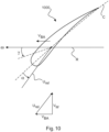
- FIG. 10 To clarify the blade angle y and the angle of attack ⁇ , these are shown in the Figure 10 for a profile section 1000.
- This profile section 1000 therefore represents a rotor blade section.
- a blade section speed V BA is obtained for the profile section 1000 under consideration, which is thus directed parallel to the rotor plane.
- the actual wind speed Vw taking into account the blade section speed V BA, leads to an apparent or relative wind speed U rel .
- the angle between this relative wind direction U rel and the profile chord c is the angle of attack ⁇ . It also depends directly on the set blade angle ⁇ , which refers to the rotor plane R.
- a small blade angle ⁇ corresponds to a setting in partial load operation.
- Figure 4 thus shows the angle of attack ⁇ over the length of a rotor blade with the total length R, whereby the total length R is actually the maximum radius of the rotor in which the rotor blade is operated and thus the maximum radius R indicates the value from the axis of rotation of the rotor to the blade tip.
- the radius r considered is normalized to this maximum radius R, so that the representation on the abscissa extends to the value 1.
- this angle of attack curve 402 assumes negative values from about halfway up the rotor blade, i.e. from about the value 0.5 for the radial position on the rotor blade, and further towards the blade tip these values become even greater in magnitude, i.e. they are even further below 0. This is an example of a rotor blade that has had its blade angle adjusted too much in storm operation, thereby reducing the speed too much. If the blade angle were adjusted less and the speed were reduced less or later, the angle of attack would not go into the negative range as much, or even not at all.
- the task for storm operation of a wind turbine is to avoid the occurrence of flow separation at negative angles of attack on the rotor blade.
- FIG. 5 shows, among other things, the wind speed-rotational speed characteristic curve 202 of the Figure 2 . It is now particularly proposed to deviate from this wind speed-rotational speed characteristic curve 202 and for this purpose an improved wind speed-rotational speed characteristic curve 502 is proposed.
- This improved wind speed-rotational speed characteristic curve 502 only begins to reduce the speed at an increased initial storm wind speed V SA2 . From there, the speed then drops with a lower initial speed gradient to the second minimum wind speed V min2 . In doing so, it reaches the first minimum speed N min1 . From there, the improved wind speed-rotational speed characteristic curve 502 drops with the amount after the increased gradient to the spin speed Nt at the maximum wind speed V max .
- this improved wind speed-rotational speed characteristic curve 502 lies above the wind speed-rotational speed characteristic curve 202.
- the first minimum speed N min1 can also form an intermediate storm speed or a storm auxiliary speed, which can also correspond in value to a storm auxiliary speed that is used in an operating characteristic curve explained later.
- This improved wind speed-speed characteristic curve 502 thus reduces the speed relatively late and then only reduces it relatively little, at least initially. Only later, namely from the second minimum wind speed V min2 or when the first minimum speed N min1 is reached, does the speed then drop steeply.
- the wind turbine can also be switched off at a higher speed, namely the second minimum speed N min2 , if the 10-minute average wind speed is above the safety wind speed V*.
- the aim of the proposal according to the improved wind speed-rotational speed characteristic curve 502 is to increase the rotational speed in storm operation, compared to previous approaches.
- the rotational speeds should therefore be reduced later and/or less as the wind speed increases, at least at the beginning of storm operation.
- the cut-off wind speed which can also be referred to as the maximum wind speed V max , remains the same and, at least according to one embodiment, a linear relationship between wind speed and rotational speed can also be used.
- Such first and second sections 504 and 506 are in the Figure 5 shown. It is therefore proposed as an improvement that the start of storm operation is shifted from the storm initial wind speed to an increased storm initial wind speed V SA2 .
- a section-by-section linear characteristic curve is proposed, which has different gradients, with the aim of increasing the speeds in the entire storm operation compared to the variant according to the Figure 2 be raised.
- preferably adapted operating characteristics are proposed, which are in the Figures 6 and 7
- the aim of changing the operating characteristics is to increase the power at a given speed.
- One way to achieve this is to shift an operating characteristic, as shown in Figure 6 is shown.
- a first operating characteristic curve is shown there, which can also be referred to as the normal operating characteristic curve 602, which, indicated by an arrow, is basically shifted to the left to the improved operating characteristic curve 604.
- This shift means that the result is that the power P shows the same curve as before, only at a lower speed. As a result, the power is increased at the same speed.
- the nominal power P N is, however, still maintained at a slightly lower speed due to the shift.
- the improved operating characteristic curve 604 which here forms a storm operating characteristic curve, initially drops from the predetermined storm initial power value P N at the predetermined storm initial speed N should with increasing wind speed Vw to a storm auxiliary power value P H at a predetermined storm auxiliary speed N H and from there drops further to the storm final power value, namely 0, at the predetermined storm final power speed Nt.
- a linear relationship between power and speed can be provided from the nominal speed N soll to the spin speed Nt.
- This is shown in Figure 7 which also shows a normal operating characteristic curve 702 for comparison, which does not represent a direct straight line, i.e. no linear relationship between power and speed.
- This normal operating characteristic 702 is changed to the improved linear operating characteristic 704 according to the arrow indicated.
- it was particularly recognized that such a linear relationship is suitable for an operating characteristic for storm operation, but is less suitable for partial load operation.
- Figure 8 illustrates the course of a blade angle ⁇ for three different cases depending on the wind speed V w in storm operation, so that Figure 8 three blade angle curves 802, 804 and 806.
- the first blade angle curve 802 can also be referred to as a normal blade angle curve and it basically belongs to the wind speed-rotational speed characteristic curve 202 according to Figure 2
- an operating characteristic according to the normal operating characteristic 602 or 702 of the Figure 6 or 7 respectively.
- a second and thus improved blade angle curve 804 is shown, which also shows the wind speed-rotational speed characteristic curve 202 of the Figure 2 but for which an improved operating characteristic curve was used. This can be based on an improved operating characteristic curve 604 or 704, or a similar one.
- Figure 9 shows the course of the angle of attack in the outer area of the rotor blade for the three blade angle curves 802, 804 and 806 for a wind speed, namely from 70 to 100 percent of the radius r in relation to the maximum radius R.
- the angle of attack curves 902, 904 and 906 are shown in the Figure 9 shown.
- the Figure 9 also the angle of attack distribution in the blade tip area, which results from the Figure 8 mentioned operational management.
- the invention therefore has the particular purpose of increasing the angle of attack, especially in the blade tip area.
- negative angles of attack can occur in the blade tip area, i.e. the stagnation point of the flow is then on the suction side of the profile.
- flow separation typically occurs on the pressure side.
- an aeroelastic-induced oscillation of the rotor blade can occur, which can lead to damage to the blade.
- the proposed invention aims to avoid reaching critical negative angles of attack in storm operation by means of a modified operating procedure and thus to ensure or at least improve the integrity of the rotor blade.
- the proposed measures can reduce the load on the rotor blades during storm operation, while at the same time enabling a higher power output.
Landscapes
- Engineering & Computer Science (AREA)
- Life Sciences & Earth Sciences (AREA)
- Sustainable Development (AREA)
- Sustainable Energy (AREA)
- Chemical & Material Sciences (AREA)
- Combustion & Propulsion (AREA)
- Mechanical Engineering (AREA)
- General Engineering & Computer Science (AREA)
- Physics & Mathematics (AREA)
- Fluid Mechanics (AREA)
- Wind Motors (AREA)
Applications Claiming Priority (2)
| Application Number | Priority Date | Filing Date | Title |
|---|---|---|---|
| DE102018100127.4A DE102018100127A1 (de) | 2018-01-04 | 2018-01-04 | Betreiben einer Windenergieanlage bei Sturm |
| PCT/EP2018/084343 WO2019134793A1 (de) | 2018-01-04 | 2018-12-11 | Betreiben einer windenergieanlage bei sturm |
Publications (2)
| Publication Number | Publication Date |
|---|---|
| EP3735532A1 EP3735532A1 (de) | 2020-11-11 |
| EP3735532B1 true EP3735532B1 (de) | 2025-01-15 |
Family
ID=64746543
Family Applications (1)
| Application Number | Title | Priority Date | Filing Date |
|---|---|---|---|
| EP18822306.9A Active EP3735532B1 (de) | 2018-01-04 | 2018-12-11 | Betreiben einer windenergieanlage bei sturm |
Country Status (7)
| Country | Link |
|---|---|
| US (1) | US11193472B2 (da) |
| EP (1) | EP3735532B1 (da) |
| CN (1) | CN111566340B (da) |
| DE (1) | DE102018100127A1 (da) |
| DK (1) | DK3735532T3 (da) |
| ES (1) | ES3014944T3 (da) |
| WO (1) | WO2019134793A1 (da) |
Families Citing this family (8)
| Publication number | Priority date | Publication date | Assignee | Title |
|---|---|---|---|---|
| EP3722595A1 (en) * | 2019-04-09 | 2020-10-14 | Siemens Gamesa Renewable Energy A/S | Controller for a wind turbine |
| CN110566404B (zh) * | 2019-08-29 | 2020-12-01 | 陕能榆林清洁能源开发有限公司 | 用于风力发电机组的功率曲线优化装置和方法 |
| EP3842633B1 (de) * | 2019-12-23 | 2024-01-10 | Wobben Properties GmbH | Verfahren zum betreiben einer windenergieanlage, windenergieanlage und windpark |
| EP3910194A1 (en) * | 2020-05-12 | 2021-11-17 | Siemens Gamesa Renewable Energy A/S | Wind turbine control arrangement |
| CN112761875B (zh) * | 2021-01-13 | 2022-11-15 | 国电联合动力技术有限公司 | 一种风电机组柔性功率自调节智能控制系统 |
| EP4053400A1 (en) * | 2021-03-01 | 2022-09-07 | Siemens Gamesa Renewable Energy A/S | Activating and deactivating a safe mode of operation of a wind turbine |
| ES3055847T3 (en) | 2021-09-09 | 2026-02-16 | Wobben Properties Gmbh | Method for adjusting a characteristic curve of a wind turbine |
| CN114856939B (zh) * | 2022-05-13 | 2024-09-13 | 华能(广东)能源开发有限公司 | 一种海上风机的降疲劳载荷控制方法、装置和主控制器 |
Citations (1)
| Publication number | Priority date | Publication date | Assignee | Title |
|---|---|---|---|---|
| EP2063111B1 (de) * | 2004-09-21 | 2013-12-25 | REpower Systems SE | Verfahren zur Regelung einer Windenergieanlage |
Family Cites Families (6)
| Publication number | Priority date | Publication date | Assignee | Title |
|---|---|---|---|---|
| DE19532409B4 (de) * | 1995-09-01 | 2005-05-12 | Wobben, Aloys, Dipl.-Ing. | Verfahren zum Betreiben einer Windenergieanlage und eine zugehörige Windenergieanlage |
| ES2701707T3 (es) * | 2007-05-03 | 2019-02-25 | Siemens Ag | Procedimiento de funcionamiento de un aerogenerador y aerogenerador |
| DE102011006670A1 (de) * | 2011-04-01 | 2012-10-04 | Aloys Wobben | Windenergieanlage und Verfahren zum Betreiben einer Windenergieanlage |
| US10495062B2 (en) * | 2015-03-05 | 2019-12-03 | Vestas Wind Systems A/S | Power ramping a turbine from a low-power mode |
| DE102015119986A1 (de) * | 2015-11-18 | 2017-05-18 | Wobben Properties Gmbh | Steuerung einer Windenergieanlage mit verstellbaren Rotorblättern |
| DE102016106590A1 (de) * | 2016-04-11 | 2017-10-12 | Wobben Properties Gmbh | Verfahren zum Betreiben einer Windenergieanlage |
-
2018
- 2018-01-04 DE DE102018100127.4A patent/DE102018100127A1/de not_active Withdrawn
- 2018-12-11 CN CN201880085297.2A patent/CN111566340B/zh active Active
- 2018-12-11 WO PCT/EP2018/084343 patent/WO2019134793A1/de not_active Ceased
- 2018-12-11 EP EP18822306.9A patent/EP3735532B1/de active Active
- 2018-12-11 ES ES18822306T patent/ES3014944T3/es active Active
- 2018-12-11 US US16/959,321 patent/US11193472B2/en active Active
- 2018-12-11 DK DK18822306.9T patent/DK3735532T3/da active
Patent Citations (1)
| Publication number | Priority date | Publication date | Assignee | Title |
|---|---|---|---|---|
| EP2063111B1 (de) * | 2004-09-21 | 2013-12-25 | REpower Systems SE | Verfahren zur Regelung einer Windenergieanlage |
Also Published As
| Publication number | Publication date |
|---|---|
| US11193472B2 (en) | 2021-12-07 |
| DE102018100127A1 (de) | 2019-07-04 |
| DK3735532T3 (da) | 2025-03-03 |
| CN111566340B (zh) | 2022-10-18 |
| WO2019134793A1 (de) | 2019-07-11 |
| ES3014944T3 (en) | 2025-04-28 |
| CN111566340A (zh) | 2020-08-21 |
| EP3735532A1 (de) | 2020-11-11 |
| US20210017957A1 (en) | 2021-01-21 |
Similar Documents
| Publication | Publication Date | Title |
|---|---|---|
| EP2063111B2 (de) | Verfahren zur Regelung einer Windenergieanlage | |
| EP3735532A1 (de) | Betreiben einer windenergieanlage bei sturm | |
| EP2906824B1 (de) | Verfahren zum betreiben einer windenergieanlage | |
| EP3377759B1 (de) | Steuerung einer windenergieanlage mit verstellbaren rotorblättern | |
| DE102010027003B4 (de) | Rotor für eine Windenergieanlage und Verfahren zur Regelung des Rotors | |
| EP3548737B1 (de) | Windenergieanlage und verfahren zum betreiben einer windenergieanlage | |
| DE102007045437A1 (de) | Verfahren zur Steuerung einer Windenergieanlage | |
| EP2923079B1 (de) | Verfahren zum betreiben einer windenergieanlage und windenergieanlage | |
| WO2019234168A1 (de) | Verfahren zum betreiben einer windenergieanlage | |
| EP3443223B1 (de) | Verfahren zum betreiben einer windenergieanlage | |
| EP3489507B1 (de) | Verfahren und vorrichtung zum betreiben einer windenergieanlage | |
| EP3810924B1 (de) | Leistungsreduzierter betrieb einer windenergieanlage | |
| EP3740674B1 (de) | Verfahren zum steuern einer windenergieanlage und windenergieanlage | |
| EP3884153B1 (de) | Reglerstruktur und regelverfahren für eine windenergieanlage | |
| EP3768970B1 (de) | Verfahren zum betreiben einer windenergieanlage, windenergieanlage und windpark | |
| EP3839249B1 (de) | Verfahren zum einstellen eines pitchwinkels eines rotorblatts, steuerungsvorrichtung zum einstellen eines pitchwinkels sowie dazugehörige windenergieanlage | |
| EP3842633B1 (de) | Verfahren zum betreiben einer windenergieanlage, windenergieanlage und windpark | |
| DE102019113044A1 (de) | Verfahren zum Auslegen und Betreiben einer Windenergieanlage, Windenergieanlage sowie Windpark | |
| DE102018130636A1 (de) | Verfahren zum Betreiben einer Windenergieanlage | |
| EP4148270B1 (de) | Verfahren zum anpassen einer betriebskennlinie einer windenergieanlage | |
| EP3887677B1 (de) | Verfahren zum betrieb einer windenergieanlage, windenergieanlage und computerprogrammprodukt |
Legal Events
| Date | Code | Title | Description |
|---|---|---|---|
| STAA | Information on the status of an ep patent application or granted ep patent |
Free format text: STATUS: UNKNOWN |
|
| STAA | Information on the status of an ep patent application or granted ep patent |
Free format text: STATUS: THE INTERNATIONAL PUBLICATION HAS BEEN MADE |
|
| PUAI | Public reference made under article 153(3) epc to a published international application that has entered the european phase |
Free format text: ORIGINAL CODE: 0009012 |
|
| STAA | Information on the status of an ep patent application or granted ep patent |
Free format text: STATUS: REQUEST FOR EXAMINATION WAS MADE |
|
| 17P | Request for examination filed |
Effective date: 20200804 |
|
| AK | Designated contracting states |
Kind code of ref document: A1 Designated state(s): AL AT BE BG CH CY CZ DE DK EE ES FI FR GB GR HR HU IE IS IT LI LT LU LV MC MK MT NL NO PL PT RO RS SE SI SK SM TR |
|
| AX | Request for extension of the european patent |
Extension state: BA ME |
|
| DAV | Request for validation of the european patent (deleted) | ||
| DAX | Request for extension of the european patent (deleted) | ||
| STAA | Information on the status of an ep patent application or granted ep patent |
Free format text: STATUS: EXAMINATION IS IN PROGRESS |
|
| 17Q | First examination report despatched |
Effective date: 20221007 |
|
| GRAP | Despatch of communication of intention to grant a patent |
Free format text: ORIGINAL CODE: EPIDOSNIGR1 |
|
| STAA | Information on the status of an ep patent application or granted ep patent |
Free format text: STATUS: GRANT OF PATENT IS INTENDED |
|
| INTG | Intention to grant announced |
Effective date: 20240809 |
|
| GRAS | Grant fee paid |
Free format text: ORIGINAL CODE: EPIDOSNIGR3 |
|
| GRAA | (expected) grant |
Free format text: ORIGINAL CODE: 0009210 |
|
| STAA | Information on the status of an ep patent application or granted ep patent |
Free format text: STATUS: THE PATENT HAS BEEN GRANTED |
|
| AK | Designated contracting states |
Kind code of ref document: B1 Designated state(s): AL AT BE BG CH CY CZ DE DK EE ES FI FR GB GR HR HU IE IS IT LI LT LU LV MC MK MT NL NO PL PT RO RS SE SI SK SM TR |
|
| REG | Reference to a national code |
Ref country code: CH Ref legal event code: EP Ref country code: GB Ref legal event code: FG4D Free format text: NOT ENGLISH |
|
| REG | Reference to a national code |
Ref country code: DE Ref legal event code: R096 Ref document number: 502018015503 Country of ref document: DE |
|
| REG | Reference to a national code |
Ref country code: IE Ref legal event code: FG4D Free format text: LANGUAGE OF EP DOCUMENT: GERMAN |
|
| REG | Reference to a national code |
Ref country code: NL Ref legal event code: FP |
|
| REG | Reference to a national code |
Ref country code: DK Ref legal event code: T3 Effective date: 20250226 |
|
| PG25 | Lapsed in a contracting state [announced via postgrant information from national office to epo] |
Ref country code: RS Free format text: LAPSE BECAUSE OF FAILURE TO SUBMIT A TRANSLATION OF THE DESCRIPTION OR TO PAY THE FEE WITHIN THE PRESCRIBED TIME-LIMIT Effective date: 20250415 |
|
| PG25 | Lapsed in a contracting state [announced via postgrant information from national office to epo] |
Ref country code: FI Free format text: LAPSE BECAUSE OF FAILURE TO SUBMIT A TRANSLATION OF THE DESCRIPTION OR TO PAY THE FEE WITHIN THE PRESCRIBED TIME-LIMIT Effective date: 20250115 |
|
| PG25 | Lapsed in a contracting state [announced via postgrant information from national office to epo] |
Ref country code: PL Free format text: LAPSE BECAUSE OF FAILURE TO SUBMIT A TRANSLATION OF THE DESCRIPTION OR TO PAY THE FEE WITHIN THE PRESCRIBED TIME-LIMIT Effective date: 20250115 |
|
| REG | Reference to a national code |
Ref country code: LT Ref legal event code: MG9D |
|
| PG25 | Lapsed in a contracting state [announced via postgrant information from national office to epo] |
Ref country code: NO Free format text: LAPSE BECAUSE OF FAILURE TO SUBMIT A TRANSLATION OF THE DESCRIPTION OR TO PAY THE FEE WITHIN THE PRESCRIBED TIME-LIMIT Effective date: 20250415 Ref country code: IS Free format text: LAPSE BECAUSE OF FAILURE TO SUBMIT A TRANSLATION OF THE DESCRIPTION OR TO PAY THE FEE WITHIN THE PRESCRIBED TIME-LIMIT Effective date: 20250515 |
|
| PG25 | Lapsed in a contracting state [announced via postgrant information from national office to epo] |
Ref country code: HR Free format text: LAPSE BECAUSE OF FAILURE TO SUBMIT A TRANSLATION OF THE DESCRIPTION OR TO PAY THE FEE WITHIN THE PRESCRIBED TIME-LIMIT Effective date: 20250115 |
|
| PG25 | Lapsed in a contracting state [announced via postgrant information from national office to epo] |
Ref country code: LV Free format text: LAPSE BECAUSE OF FAILURE TO SUBMIT A TRANSLATION OF THE DESCRIPTION OR TO PAY THE FEE WITHIN THE PRESCRIBED TIME-LIMIT Effective date: 20250115 Ref country code: PT Free format text: LAPSE BECAUSE OF FAILURE TO SUBMIT A TRANSLATION OF THE DESCRIPTION OR TO PAY THE FEE WITHIN THE PRESCRIBED TIME-LIMIT Effective date: 20250515 |
|
| PG25 | Lapsed in a contracting state [announced via postgrant information from national office to epo] |
Ref country code: BG Free format text: LAPSE BECAUSE OF FAILURE TO SUBMIT A TRANSLATION OF THE DESCRIPTION OR TO PAY THE FEE WITHIN THE PRESCRIBED TIME-LIMIT Effective date: 20250115 Ref country code: GR Free format text: LAPSE BECAUSE OF FAILURE TO SUBMIT A TRANSLATION OF THE DESCRIPTION OR TO PAY THE FEE WITHIN THE PRESCRIBED TIME-LIMIT Effective date: 20250416 |
|
| PG25 | Lapsed in a contracting state [announced via postgrant information from national office to epo] |
Ref country code: SE Free format text: LAPSE BECAUSE OF FAILURE TO SUBMIT A TRANSLATION OF THE DESCRIPTION OR TO PAY THE FEE WITHIN THE PRESCRIBED TIME-LIMIT Effective date: 20250115 |
|
| PG25 | Lapsed in a contracting state [announced via postgrant information from national office to epo] |
Ref country code: SM Free format text: LAPSE BECAUSE OF FAILURE TO SUBMIT A TRANSLATION OF THE DESCRIPTION OR TO PAY THE FEE WITHIN THE PRESCRIBED TIME-LIMIT Effective date: 20250115 |
|
| PG25 | Lapsed in a contracting state [announced via postgrant information from national office to epo] |
Ref country code: IT Free format text: LAPSE BECAUSE OF FAILURE TO SUBMIT A TRANSLATION OF THE DESCRIPTION OR TO PAY THE FEE WITHIN THE PRESCRIBED TIME-LIMIT Effective date: 20250115 |
|
| REG | Reference to a national code |
Ref country code: DE Ref legal event code: R097 Ref document number: 502018015503 Country of ref document: DE |
|
| PG25 | Lapsed in a contracting state [announced via postgrant information from national office to epo] |
Ref country code: CZ Free format text: LAPSE BECAUSE OF FAILURE TO SUBMIT A TRANSLATION OF THE DESCRIPTION OR TO PAY THE FEE WITHIN THE PRESCRIBED TIME-LIMIT Effective date: 20250115 Ref country code: EE Free format text: LAPSE BECAUSE OF FAILURE TO SUBMIT A TRANSLATION OF THE DESCRIPTION OR TO PAY THE FEE WITHIN THE PRESCRIBED TIME-LIMIT Effective date: 20250115 |
|
| PG25 | Lapsed in a contracting state [announced via postgrant information from national office to epo] |
Ref country code: RO Free format text: LAPSE BECAUSE OF FAILURE TO SUBMIT A TRANSLATION OF THE DESCRIPTION OR TO PAY THE FEE WITHIN THE PRESCRIBED TIME-LIMIT Effective date: 20250115 |
|
| PG25 | Lapsed in a contracting state [announced via postgrant information from national office to epo] |
Ref country code: SK Free format text: LAPSE BECAUSE OF FAILURE TO SUBMIT A TRANSLATION OF THE DESCRIPTION OR TO PAY THE FEE WITHIN THE PRESCRIBED TIME-LIMIT Effective date: 20250115 |
|
| PLBE | No opposition filed within time limit |
Free format text: ORIGINAL CODE: 0009261 |
|
| STAA | Information on the status of an ep patent application or granted ep patent |
Free format text: STATUS: NO OPPOSITION FILED WITHIN TIME LIMIT |
|
| REG | Reference to a national code |
Ref country code: CH Ref legal event code: L10 Free format text: ST27 STATUS EVENT CODE: U-0-0-L10-L00 (AS PROVIDED BY THE NATIONAL OFFICE) Effective date: 20251126 |
|
| 26N | No opposition filed |
Effective date: 20251016 |
|
| PGFP | Annual fee paid to national office [announced via postgrant information from national office to epo] |
Ref country code: GB Payment date: 20251218 Year of fee payment: 8 |
|
| PGFP | Annual fee paid to national office [announced via postgrant information from national office to epo] |
Ref country code: DK Payment date: 20251217 Year of fee payment: 8 |
|
| PGFP | Annual fee paid to national office [announced via postgrant information from national office to epo] |
Ref country code: NL Payment date: 20251217 Year of fee payment: 8 Ref country code: FR Payment date: 20251217 Year of fee payment: 8 |
|
| PGFP | Annual fee paid to national office [announced via postgrant information from national office to epo] |
Ref country code: TR Payment date: 20251204 Year of fee payment: 8 |
|
| PGFP | Annual fee paid to national office [announced via postgrant information from national office to epo] |
Ref country code: ES Payment date: 20260119 Year of fee payment: 8 |
|
| PGFP | Annual fee paid to national office [announced via postgrant information from national office to epo] |
Ref country code: DE Payment date: 20260119 Year of fee payment: 8 |
|
| PG25 | Lapsed in a contracting state [announced via postgrant information from national office to epo] |
Ref country code: LT Free format text: LAPSE BECAUSE OF FAILURE TO SUBMIT A TRANSLATION OF THE DESCRIPTION OR TO PAY THE FEE WITHIN THE PRESCRIBED TIME-LIMIT Effective date: 20250115 |
|
| PG25 | Lapsed in a contracting state [announced via postgrant information from national office to epo] |
Ref country code: MC Free format text: LAPSE BECAUSE OF FAILURE TO SUBMIT A TRANSLATION OF THE DESCRIPTION OR TO PAY THE FEE WITHIN THE PRESCRIBED TIME-LIMIT Effective date: 20250115 |
|
| REG | Reference to a national code |
Ref country code: CH Ref legal event code: H13 Free format text: ST27 STATUS EVENT CODE: U-0-0-H10-H13 (AS PROVIDED BY THE NATIONAL OFFICE) Effective date: 20260723 |