EP3735533B1 - Verfahren zum steuern einer windenergieanlage sowie windenergieanlage - Google Patents
Verfahren zum steuern einer windenergieanlage sowie windenergieanlage Download PDFInfo
- Publication number
- EP3735533B1 EP3735533B1 EP19700077.1A EP19700077A EP3735533B1 EP 3735533 B1 EP3735533 B1 EP 3735533B1 EP 19700077 A EP19700077 A EP 19700077A EP 3735533 B1 EP3735533 B1 EP 3735533B1
- Authority
- EP
- European Patent Office
- Prior art keywords
- rotor
- speed
- length
- wind turbine
- rotor blade
- Prior art date
- Legal status (The legal status is an assumption and is not a legal conclusion. Google has not performed a legal analysis and makes no representation as to the accuracy of the status listed.)
- Active
Links
Images

Classifications
-
- F—MECHANICAL ENGINEERING; LIGHTING; HEATING; WEAPONS; BLASTING
- F03—MACHINES OR ENGINES FOR LIQUIDS; WIND, SPRING, OR WEIGHT MOTORS; PRODUCING MECHANICAL POWER OR A REACTIVE PROPULSIVE THRUST, NOT OTHERWISE PROVIDED FOR
- F03D—WIND MOTORS
- F03D7/00—Controlling wind motors
- F03D7/02—Controlling wind motors the wind motors having rotation axis substantially parallel to the air flow entering the rotor
- F03D7/022—Adjusting aerodynamic properties of the blades
- F03D7/0236—Adjusting aerodynamic properties of the blades by changing the active surface of the wind engaging parts, e.g. reefing or furling
-
- F—MECHANICAL ENGINEERING; LIGHTING; HEATING; WEAPONS; BLASTING
- F05—INDEXING SCHEMES RELATING TO ENGINES OR PUMPS IN VARIOUS SUBCLASSES OF CLASSES F01-F04
- F05B—INDEXING SCHEME RELATING TO WIND, SPRING, WEIGHT, INERTIA OR LIKE MOTORS, TO MACHINES OR ENGINES FOR LIQUIDS COVERED BY SUBCLASSES F03B, F03D AND F03G
- F05B2240/00—Components
- F05B2240/20—Rotors
- F05B2240/202—Rotors with adjustable area of intercepted fluid
- F05B2240/2021—Rotors with adjustable area of intercepted fluid by means of telescoping blades
-
- F—MECHANICAL ENGINEERING; LIGHTING; HEATING; WEAPONS; BLASTING
- F05—INDEXING SCHEMES RELATING TO ENGINES OR PUMPS IN VARIOUS SUBCLASSES OF CLASSES F01-F04
- F05B—INDEXING SCHEME RELATING TO WIND, SPRING, WEIGHT, INERTIA OR LIKE MOTORS, TO MACHINES OR ENGINES FOR LIQUIDS COVERED BY SUBCLASSES F03B, F03D AND F03G
- F05B2270/00—Control
- F05B2270/30—Control parameters, e.g. input parameters
- F05B2270/324—Air pressure
-
- F—MECHANICAL ENGINEERING; LIGHTING; HEATING; WEAPONS; BLASTING
- F05—INDEXING SCHEMES RELATING TO ENGINES OR PUMPS IN VARIOUS SUBCLASSES OF CLASSES F01-F04
- F05B—INDEXING SCHEME RELATING TO WIND, SPRING, WEIGHT, INERTIA OR LIKE MOTORS, TO MACHINES OR ENGINES FOR LIQUIDS COVERED BY SUBCLASSES F03B, F03D AND F03G
- F05B2270/00—Control
- F05B2270/30—Control parameters, e.g. input parameters
- F05B2270/325—Air temperature
-
- F—MECHANICAL ENGINEERING; LIGHTING; HEATING; WEAPONS; BLASTING
- F05—INDEXING SCHEMES RELATING TO ENGINES OR PUMPS IN VARIOUS SUBCLASSES OF CLASSES F01-F04
- F05B—INDEXING SCHEME RELATING TO WIND, SPRING, WEIGHT, INERTIA OR LIKE MOTORS, TO MACHINES OR ENGINES FOR LIQUIDS COVERED BY SUBCLASSES F03B, F03D AND F03G
- F05B2270/00—Control
- F05B2270/30—Control parameters, e.g. input parameters
- F05B2270/327—Rotor or generator speeds
-
- F—MECHANICAL ENGINEERING; LIGHTING; HEATING; WEAPONS; BLASTING
- F05—INDEXING SCHEMES RELATING TO ENGINES OR PUMPS IN VARIOUS SUBCLASSES OF CLASSES F01-F04
- F05B—INDEXING SCHEME RELATING TO WIND, SPRING, WEIGHT, INERTIA OR LIKE MOTORS, TO MACHINES OR ENGINES FOR LIQUIDS COVERED BY SUBCLASSES F03B, F03D AND F03G
- F05B2270/00—Control
- F05B2270/30—Control parameters, e.g. input parameters
- F05B2270/337—Electrical grid status parameters, e.g. voltage, frequency or power demand
-
- Y—GENERAL TAGGING OF NEW TECHNOLOGICAL DEVELOPMENTS; GENERAL TAGGING OF CROSS-SECTIONAL TECHNOLOGIES SPANNING OVER SEVERAL SECTIONS OF THE IPC; TECHNICAL SUBJECTS COVERED BY FORMER USPC CROSS-REFERENCE ART COLLECTIONS [XRACs] AND DIGESTS
- Y02—TECHNOLOGIES OR APPLICATIONS FOR MITIGATION OR ADAPTATION AGAINST CLIMATE CHANGE
- Y02E—REDUCTION OF GREENHOUSE GAS [GHG] EMISSIONS, RELATED TO ENERGY GENERATION, TRANSMISSION OR DISTRIBUTION
- Y02E10/00—Energy generation through renewable energy sources
- Y02E10/70—Wind energy
- Y02E10/72—Wind turbines with rotation axis in wind direction
Definitions
- the present invention relates to a method for controlling a wind power plant and a wind power plant.
- a wind turbine has an aerodynamic rotor with a number of rotor blades, in particular three.
- the electricity production costs (Cost of Energy) are still very high for a wind turbine.
- the electricity production costs can be reduced, for example, by using a wind turbine with a variable length of the rotor blades. In particular, this can be done by limiting the maximum impact bending moments (reduced rotor circular area in the upper wind speed range) with simultaneous optimal energy yield (enlarged rotor circular area in the lower wind speed range) compared to conventional rotor blades.
- U.S. 6,972,498 B2 and US 2003/0044274 A1 describe a wind turbine with rotor blades whose length can be varied. The length of the rotor blades is reduced when the wind speed exceeds a limit or when the power generated by the wind turbine exceeds a limit.
- German Patent and Trademark Office has researched the following documents in the German patent application on which priority is based: DE 10 2010 054 013 A1 , DE 10 2010 054 014 A1 , U.S. 6,972,498 B2 , U.S. 7,071,578 B1 , U.S. 2003/0 223 868 A1 and US 2012/0 093 627 A1 .
- a method for controlling a wind turbine having an aerodynamic rotor with a variable radius is provided.
- the aerodynamic rotor has at least one rotor blade, the length of which can be adjusted.
- a speed and / or torque of the aerodynamic rotor and an air density in the area Wind turbine is detected and the length of the at least one rotor blade is controlled depending on the speed and / or the torque of the aerodynamic rotor and the detected air density in the vicinity of the wind turbine.
- a specified maximum permissible sound pressure is also taken into account.
- the detected rotational speed and/or the detected torque of the aerodynamic rotor is compared with a threshold value.
- the length of the at least one rotor blade is reduced as the speed and/or torque increases, if the speed and/or the torque is greater than the threshold value.
- the sensed air density is compared to at least one air density threshold and the length of the at least one rotor blade is reduced when the speed and/or torque is above a second threshold.
- the second threshold value of the speed and/or the torque is greater than the first threshold value of the speed and/or the torque.
- the invention also relates to a wind turbine with an aerodynamic rotor with at least one telescopic rotor blade, i.e. its length is adjustable.
- Each rotor blade has a first and second section and an adjustment unit, by means of which the second section can be adjusted along a longitudinal direction of the rotor blade in order to adjust the length of the rotor blade.
- the wind turbine also has a sensor for detecting an air density and a control unit which is coupled to the adjustment units of the at least one rotor blade and has a speed and/or a torque of the aerodynamic rotor and the air density as input variables and is designed to determine the length of the to control at least one rotor blade depending on the speed and/or the torque of the aerodynamic rotor of the wind turbine, the air density and a predetermined maximum permissible sound pressure level.
- the controller is configured to reduce the length of the rotor blade when the speed is above a second threshold, the second threshold speed being set inversely proportional to air density.
- control unit is designed to receive an air density in the area surrounding the wind energy installation as an input variable and to control the length of the at least one rotor blade as a function of the air density.
- the invention relates to the idea of controlling a wind power plant with rotor blades whose length is variable.
- the length of the rotor blades depends on the speed and/or the torque of the aerodynamic rotor of the wind turbine.
- the length of the rotor blades can be reduced as a function of an increasing speed and/or an increasing torque if, for example, a limit value of a speed and/or a torque has been exceeded.
- the length of the rotor blades can also depend on a maximum aerodynamic impact bending moment, a maximum permissible blade tip speed, a permissible profile angle of attack in the operating range and/or a design-provided maximum telescoping speed.
- the wind energy installation 100 has a tower 102, a nacelle 104, an aerodynamic rotor 106 which has a spinner 110 and three rotor blades 200.
- the aerodynamic Rotor 106 is rotated by the wind.
- the aerodynamic rotor 106 is coupled to an electrical generator, not shown, and rotation of the aerodynamic rotor results in rotation of the electrical generator, which in turn can generate electrical power therefrom.
- the rotor blades 200 have an adjustable pitch angle.
- the rotor blades 200 also have a first and second section 210, 220 and the length of the rotor blade and thus the radius of the aerodynamic rotor 106 is variable.
- the length L of the rotor blade 200 is determined by the first and second sections 210, 220.
- the first section 210 of the rotor blade 200 is attached to the aerodynamic rotor 106 .
- the second section 220 is attached to the first section 210 of the rotor blade in such a way that the length L of the rotor blade can be varied. This can be done, for example, by the second section 220 being movable in or relative to the first section 210 .
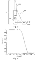
- FIG. 12 shows a schematic representation of a variable length rotor blade.
- the rotor blade 200 has a first section 210 and a second section 220, which can be moved in a longitudinal direction of the rotor blade by means of an adjustment unit 230, so that the length L of the rotor blade 200 can be adjusted.
- the first section 210 can represent the rotor blade root of the rotor blade 200 and can be attached to a hub of the wind turbine.
- the adjustment unit 230 enables the second section 220 to be moved along a longitudinal direction of the rotor blade 200 .
- the adjustment unit 230 is coupled to a control unit 300 .
- the control unit 300 controls the adjusting unit 230 in order to adjust the length L of the rotor blade.
- the control unit 300 has an input for the speed n and/or for the torque M and optionally an input for the current air density p.
- the control unit 300 can control the operation of the adjustment unit 230 and thus the length of the rotor blade 200 as a function of the rotational speed and/or the torque and optionally as a function of the air density.
- the rotational speed n and/or the torque M of the aerodynamic rotor 106 of the wind turbine can thus serve as an input variable for controlling the length of the rotor blade.
- each rotor blade 200 can have an adjustable length and an adjustment unit.
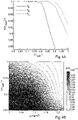
- FIG 3 shows a graph to illustrate the dependency of the radius R of the aerodynamic rotor as a function of the speed. From a threshold can at increasing speed of the radius R of the aerodynamic rotor 106 can be reduced. This can be done by the control unit 300, which is coupled to the adjustment units 230 of each rotor blade 200. By varying the length of the rotor blades, the radius of the aerodynamic rotor is also changed.
- the dependency of the radius of the aerodynamic rotor on the speed is also influenced by a specified maximum aerodynamic impact bending moment, a maximum permissible sound pressure level, a permissible angle of attack in the operating range and/or a design-specified, maximum telescoping speed.
- the impact bending moment of the system with a rotor diameter equal to the dimension of the retracted variable rotor can be used as a limit value for the maximum aerodynamic impact bending moment when designing the radius characteristic.
- SPL f v hint
- the sound pressure level SPL also depends on atmospheric conditions (density and temperature).
- Figure 4A shows a graph to illustrate the dependence of the radius of the aerodynamic rotor on the speed for different air densities.
- Figure 4A shows the characteristic curve of the radius of the aerodynamic rotor at three different air densities.
- ⁇ C ⁇ ⁇ B ⁇ ⁇ A applies
- Figure 4B shows a graph illustrating the relationship between aerodynamic rotor radius, aerodynamic rotor speed and various air densities.
- the effect of the air density on the relationship between the radius R of the aerodynamic rotor and the speed n can be explained by the fact that a lower air density allows a reserve in the maximum flapping moment and in the maximum permissible blade tip speed. If air density is taken into account when controlling the radius of the aerodynamic rotor, this can lead to a delayed reduction in the length of the rotor blades and thus the radius of the aerodynamic rotor. This in turn enables a better energy yield.
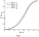
- figure 5 shows a graph to illustrate a performance curve of a conventional wind turbine and a wind turbine with an aerodynamic rotor whose radius is variable.
- the curve WEA-A describes a conventional wind energy installation with a radius which corresponds to the smallest possible radius of the wind energy installation according to the invention.
- the performance of this wind turbine is shown for two different air densities, ⁇ A and ⁇ B .
- the wind turbine WEA-C represents a wind turbine with a variable rotor radius.
- the air density ⁇ B is smaller than the air density ⁇ A.
- control of the radius or the diameter of the aerodynamic rotor and thus the length of the rotor blades can be defined as a rigid characteristic.
- the radius of the aerodynamic rotor can additionally or alternatively be controlled on the basis of measurement data such as, for example, the impact bending moment at the rotor blade root.
- the wind energy installation according to the invention represents a speed-variable, pitch-controlled wind energy installation which can adjust the length of the rotor blades and thus the radius or the diameter of the aerodynamic rotor.
- the length of the rotor blades is controlled based on the rotor speed/torque and optionally the air density.
- the effectiveness and thus the annual yields can be improved without likewise increasing the mechanical load on the wind energy plant and in particular the extreme loads.
- the increase in annual yield tends to be greater the lower the mean annual wind speed and the mean density.
Landscapes
- Engineering & Computer Science (AREA)
- Physics & Mathematics (AREA)
- Fluid Mechanics (AREA)
- Life Sciences & Earth Sciences (AREA)
- Sustainable Development (AREA)
- Sustainable Energy (AREA)
- Chemical & Material Sciences (AREA)
- Combustion & Propulsion (AREA)
- Mechanical Engineering (AREA)
- General Engineering & Computer Science (AREA)
- Wind Motors (AREA)
Description
- Die vorliegende Erfindung betrifft ein Verfahren zum Steuern einer Windenergieanlage sowie eine Windenergieanlage.
- Eine Windenergieanlage weist einen aerodynamischen Rotor mit einer Anzahl von Rotorblättern, insbesondere drei auf. Nach wie vor sind die Stromgestehungskosten (Cost of Energy) sehr hoch für eine Windenergieanlage. Die Stromgestehungskosten können beispielsweise durch eine Windenergieanlage mit einer variablen Länge der Rotorblätter reduziert werden. Insbesondere kann dies durch Begrenzung der maximalen Schlagbiegemomente (verkleinerte Rotorkreisfläche im oberen Windgeschwindigkeitsbereich) bei gleichzeitig optimaler Energieausbeute (vergrößerte Rotorkreisfläche im unteren Windgeschwindigkeitsbereich) verglichen mit konventionellen Rotorblättern, erfolgen.
-
US 6,972,498 B2 undUS 2003/0044274 A1 beschreiben eine Windenergieanlage mit Rotorblättern, deren Länge variierbar ist. Die Länge der Rotorblätter wird reduziert, wenn die Windgeschwindigkeit einen Grenzwert überschreitet, oder wenn die durch die Windenergieanlage erzeugte Leistung einen Grenzwert überschreitet. - In der prioritätsbegründenden deutschen Patentanmeldung hat das Deutsche Patent- und Markenamt die folgenden Dokumente recherchiert:
DE 10 2010 054 013 A1 ,DE 10 2010 054 014 A1 ,US 6 972 498 B2 ,US 7 071 578 B1 ,US 2003 / 0 223 868 A1 undUS 2012/0 093 627 A1 . - Es ist daher eine Aufgabe der vorliegenden Erfindung ein Verfahren zum Steuern einer Windenergieanlage mit Rotorblättern mit variabler Länge vorzusehen.
- Diese Aufgabe wird durch ein Verfahren nach Anspruch 1 gelöst.
- Somit wird ein Verfahren zum Steuern einer Windenergieanlage vorgesehen, welche einen aerodynamischen Rotor mit einem variablen Radius aufweist. Der aerodynamische Rotor weist mindestens ein Rotorblatt auf, dessen Länge einstellbar ist. Eine Drehzahl und/oder ein Drehmoment des aerodynamischen Rotors sowie eine Luftdichte in der Umgebung der Windenergieanlage wird erfasst und die Länge des mindestens einen Rotorblattes wird in Abhängigkeit der Drehzahl und/oder des Drehmoments des aerodynamischen Rotors sowie der erfassten Luftdichte in der Umgebung der Windenergieanlage gesteuert. Ferner wird ein vorgegebener maximal zulässiger Schalldruck mit berücksichtigt.
- Gemäß einem weiteren Aspekt der vorliegenden Erfindung wird die erfasste Drehzahl und/oder das erfasste Drehmoment des aerodynamischen Rotors mit einem Schwellwert verglichen. Die Länge des mindestens einen Rotorblattes wird bei steigender Drehzahl und/oder steigendem Drehmoment reduziert, wenn die Drehzahl und/oder das Drehmoment größer als der Schwellwert ist.
- Gemäß der vorliegenden Erfindung wird die erfasste Luftdichte mit mindestens einem Luftdichteschwellwert verglichen und die Länge des mindestens einen Rotorblattes wird reduziert, wenn die Drehzahl und/oder das Drehmoment über einem zweiten Schwellwert liegt. Der zweite Schwellwert der Drehzahl und/oder das Drehmoment ist größer als der erste Schwellwert der Drehzahl und/oder des Drehmomentes.
- Die Erfindung betrifft ebenfalls eine Windenergieanlage mit einem aerodynamischen Rotor mit mindestens einem teleskopierbaren Rotorblatt, d.h. seine Länge ist einstellbar. Jedes Rotorblatt weist einen ersten und zweiten Abschnitt und eine Verstelleinheit auf, mittels welcher der zweite Abschnitt entlang einer Längsrichtung des Rotorblattes verstellbar ist, um die Länge des Rotorblattes einzustellen. Die Windenergieanlage weist ferner einen Sensor zum Erfassen einer Luftdichte und eine Steuereinheit auf, weiche mit den Verstelleinheiten des mindestens einen Rotorblattes gekoppelt ist und eine Drehzahl und/oder ein Drehmoment des aerodynamischen Rotors sowie die Luftdichte als Eingangsgröße aufweist und dazu ausgestaltet ist, die Länge des mindestens einen Rotorblattes in Abhängigkeit der Drehzahl und/oder des Drehmomentes des aerodynamischen Rotors der Windenergieanlage, der Luftdichte und eines vorgegebenen maximal zulässigen Schalldrucks zu steuern. Die Steuereinheit ist dazu ausgestaltet, die Länge des Rotorblattes zu reduzieren, wenn die Drehzahl über einem zweiten Schwellwert liegt, wobei der zweite Schwellwert der Drehzahl umgekehrt proportional zur Luftdichte gesetzt wird.
- Gemäß einem weiteren Aspekt der vorliegenden Erfindung ist die Steuereinheit dazu ausgestaltet, eine Luftdichte in der Umgebung der Windenergieanlage als Eingangsgröße zu empfangen und die Länge des mindestens einen Rotorblattes auch in Abhängigkeit der Luftdichte zu steuern.
- Die Erfindung betrifft den Gedanken, eine Windenergieanlage mit Rotorblättern zu steuern, deren Länge variabel ist. Die Länge der Rotorblätter wird in Abhängigkeit der Drehzahl und/oder des Drehmomentes des aerodynamischen Rotors der Windenergieanlage gesteuert. Hierbei kann die Länge der Rotorblätter in Abhängigkeit einer steigenden Drehzahl und/oder eines steigenden Drehmomentes reduziert werden, sofern beispielsweise ein Grenzwert einer Drehzahl und/oder eines Drehmomentes überschritten worden ist.
- Die Länge der Rotorblätter kann ferner abhängig sein von einem maximalen aerodynamischen Schlagbiegemoment, einer maximal zulässigen Blattspitzengeschwindigkeit, einem zulässigen Profilanstellwinkel im Betriebsbereich und/oder einer konstruktiv-vorgesehenen, maximalen Teleskopiergeschwindigkeit.
- Weitere Ausgestaltungen der Erfindung sind Gegenstand der Unteransprüche.
- Vorteile und Ausführungsbeispiele der Erfindung werden nachstehend unter Bezugnahme auf die Zeichnung näher erläutert.
- Fig. 1
- zeigt eine schematische Darstellung einer Windenergieanlage gemäß der Erfindung,
- Fig. 2
- zeigt eine schematische Darstellung eines Rotorblatts mit variabler Länge,
- Fig. 3
- zeigt einen Graphen zur Veranschaulichung der Abhängigkeit des Radius des aerodynamischen Rotors in Abhängigkeit der Drehzahl,
- Fig. 4A
- zeigt einen Graphen zur Veranschaulichung der Abhängigkeit des Radius des aerodynamischen Rotors in Abhängigkeit der Drehzahl für verschiedene Luftdichten,
- Fig. 4B
- zeigt einen Graphen zur Veranschaulichung des Zusammenhangs zwischen dem Radius des aerodynamischen Rotors, der Drehzahl des aerodynamischen Rotors und verschiedener Luftdichten, und
- Fig. 5
- zeigt einen Graphen zur Veranschaulichung einer Leistungskurve einer konventionellen Windenergieanlage sowie einer Windenergieanlage mit einem aerodynamischen Rotor, dessen Radius variabel ist.
-
Fig. 1 zeigt eine schematische Darstellung einer Windenergieanlage gemäß der Erfindung. Die Windenergieanlage 100 weist einen Turm 102, eine Gondel 104, einen aerodynamischen Rotor 106 auf, der einen Spinner 110 sowie drei Rotorblätter 200 aufweist. Der aerodynamische Rotor 106 wird durch den Wind in eine Drehbewegung versetzt. Der aerodynamische Rotor 106 ist mit einem nicht gezeigten elektrischen Generator gekoppelt und eine Drehung des aerodynamischen Rotors führt zu einer Drehung des elektrischen Generators, der daraus wiederum elektrische Leistung erzeugen kann. - Die Rotorblätter 200 weisen einen einstellbaren Pitchwinkel auf. Die Rotorblätter 200 weisen ferner einen ersten und zweiten Abschnitt 210, 220 auf und die Länge des Rotorblattes und damit der Radius des aerodynamischen Rotors 106 ist variabel. Die Länge L des Rotorblattes 200 wird durch den ersten und zweiten Abschnitt 210, 220 bestimmt. Der erste Abschnitt 210 des Rotorblattes 200 wird an dem aerodynamischen Rotor 106 befestigt. Der zweite Abschnitt 220 wird an dem ersten Abschnitt 210 des Rotorblatts derart befestigt, dass die Länge L des Rotorblattes variiert werden kann. Dies kann beispielsweise dadurch erfolgen, dass der zweite Abschnitt 220 in bzw. relativ zu dem ersten Abschnitt 210 verfahrbar ist.
-
Fig. 2 zeigt eine schematische Darstellung eines Rotorblattes mit variabler Länge. Das Rotorblatt 200 weist einen ersten Abschnitt 210 und einen zweiten Abschnitt 220 auf, welcher mittels einer Verstelleinheit 230 in einer Längsrichtung des Rotorblattes verfahrbar ist, so dass die Länge L des Rotorblattes 200 verstellt werden kann. Hierbei kann der erste Abschnitt 210 die Rotorblattwurzel des Rotorblatts 200 darstellen und kann an einer Nabe der Windenergieanlage befestigt werden. Die Verstelleinheit 230 ermöglicht ein Verfahren des zweiten Abschnitts 220 entlang einer Längsrichtung des Rotorblattes 200. Die Verstelleinheit 230 ist mit einer Steuereinheit 300 gekoppelt. Die Steuereinheit 300 steuert die Verstelleinheit 230, um die Länge L des Rotorblattes einzustellen. Die Steuereinheit 300 weist einen Eingang für die Drehzahl n und/oder für den Drehmoment M sowie optional einen Eingang für die aktuelle Luftdichte p auf. In Abhängigkeit der Drehzahl und/oder des Drehmomentes sowie optional in Abhängigkeit der Luftdichte kann die Steuereinheit 300 den Betrieb der Verstelleinheit 230 und damit die Länge des Rotorblattes 200 steuern. Damit kann die Drehzahl n und/oder der Drehmoment M des aerodynamischen Rotors 106 der Windenergieanlage als Eingangsgröße für die Steuerung der Länge des Rotorblattes dienen. - Gemäß der Erfindung kann jedes Rotorblatt 200 über eine einstellbare Länge und eine Verstelleinheit verfügen.
-
Fig. 3 zeigt einen Graphen zur Veranschaulichung der Abhängigkeit des Radius R des aerodynamischen Rotors in Abhängigkeit der Drehzahl. Ab einem Schwellwert kann bei steigender Drehzahl der Radius R des aerodynamischen Rotors 106 reduziert werden. Dies kann durch die Steuereinheit 300, welche mit den Verstelleinheiten 230 jedes Rotorblattes 200 gekoppelt ist, erfolgen. Durch Variation der Länge der Rotorblätter wird auch der Radius des aerodynamischen Rotors verändert. - Gemäß der Erfindung wird der Radius R des aerodynamischen Rotors in Abhängigkeit der Drehzahl gemäß der folgenden Radiuskennlinie gesteuert:

- Alternativ oder zusätzlich kann eine Steuerung der Länge des Rotorblattes in Abhängigkeit vom Drehmoment M erfolgen:

- Die Änderung der Blattlänge R hat über den Zusammenhang

- Die Abhängigkeit des Radius des aerodynamischen Rotors von der Drehzahl wird ferner durch ein vorgegebenes maximales aerodynamisches Schlagbiegemoment, einen maximal zulässigen Schalldruckpegel, einen zulässigen Anstellwinkel im Betriebsbereich und/oder einer konstruktiv-vorgegebenen, maximalen Teleskopiergeschwindigkeit beeinflusst.
- Für das maximal aerodynamische Schlagbiegemoment kann erfindungsgemäß bei der Auslegung der Radiuskennlinie als Grenzwert das Schlagbiegemoment der Anlage mit einem Rotordurchmesser gleich der Dimension des eingefahrenen variablen Rotors verwendet werden.
- Für einen maximalen Schalldruckpegel (Sound Pressure Level, SPL) muss eine Begrenzung der Blattspitzengeschwindigkeit vorgesehen werden. Es gilt:

- Der Schalldruckpegel SPL ist neben der Blattspitzengeschwindigkeit auch abhängig von atmosphärischen Bedingungen (Dichte und Temperatur). Eine maximale zulässige Blattspitzengeschwindigkeit ergibt sich in Abhängigkeit der Luftdichte ρ aus:

- Damit ist die Funktion des Radius des aerodynamischen Rotors der Windenergieanlage sowohl abhängig von der Drehzahl oder des Drehmomentes M als auch von der Luftdichte:


-
Fig. 4A zeigt einen Graphen zur Veranschaulichung der Abhängigkeit des Radius des aerodynamischen Rotors von der Drehzahl für verschiedene Luftdichten. InFig. 4A ist die Kennlinie des Radius des aerodynamischen Rotors bei drei verschiedenen Luftdichten dargestellt. Hierbei gilt ρC < ρB < ρA -
Fig. 4B zeigt einen Graphen zur Veranschaulichung des Zusammenhangs zwischen dem Radius des aerodynamischen Rotors, der Drehzahl des aerodynamischen Rotors und verschiedener Luftdichten. Die Auswirkung der Luftdichte auf die Abhängigkeit zwischen dem Radius R des aerodynamischen Rotors und der Drehzahl n lässt sich dadurch erklären, dass eine geringere Luftdichte eine Reserve in dem maximalen Schlagbiegemoment sowie in der maximal zulässigen Blattspitzengeschwindigkeit ermöglicht. Wenn die Luftdichte bei der Regelung des Radius des aerodynamischen Rotors mit berücksichtigt wird, kann dies zu einer verzögerten Reduktion der Länge der Rotorblätter und damit des Radius des aerodynamischen Rotors führen. Dies wiederum ermöglicht eine bessere Energieausbeute. -
Fig. 5 zeigt einen Graphen zur Veranschaulichung einer Leistungskurve einer konventionellen Windenergieanlage sowie einer Windenergieanlage mit einem aerodynamischen Rotor, dessen Radius variabel ist. InFig. 5 sind vier verschiedene Kennlinien der Ausgangsleistung in Abhängigkeit der Windgeschwindigkeit dargestellt. Die Kurve WEA-A beschreibt eine konventionelle Windenergieanlage mit einem Radius, welcher dem kleinstmöglichsten Radius der erfindungsgemäßen Windenergieanlage entspricht. Die Leistung dieser Windenergieanlage ist für zwei verschiedene Luftdichten, ρA und ρB, dargestellt. Die Windenergieanlage WEA-C stellt eine Windenergieanlage mit einem variablen Rotorradius dar. InFig. 5 ist die Luftdichte ρB kleiner der Luftdichte ρA. - Bei der erfindungsgemäßen Windenergieanlage kann die Steuerung des Radius bzw. des Durchmessers des aerodynamischen Rotors und damit der Länge der Rotorblätter als starre Kennlinie festgelegt werden.
- Gemäß einem weiteren Aspekt der vorliegenden Erfindung kann die Steuerung des Radius des aerodynamischen Rotors zusätzlich oder alternativ dazu basierend auf Messdaten wie beispielsweise des Schlagbiegemoments an der Rotorblattwurzel erfolgen.
- Die erfindungsgemäße Windenergieanlage stellt eine drehzahlvariable, pitchgesteuerte Windenergieanlage dar, welche die Länge der Rotorblätter und damit den Radius bzw. den Durchmesser des aerodynamischen Rotors einstellen kann. Anhand der Rotordrehzahl/des Drehmomentes und optional der Luftdichte wird die Länge der Rotorblätter gesteuert.
- Mit der erfindungsgemäßen Windenergieanlage kann die Effektivität und damit die Jahreserträge verbessert werden, ohne dabei ebenfalls die mechanische Belastung der Windenergieanlage und insbesondere die Extremlasten zu erhöhen. Die Erhöhung des Jahresertrags ist tendenziell umso größer je geringer die mittlere Jahreswindgeschwindigkeit und die mittlere Dichte ist.
Claims (3)
- Verfahren zum Steuern einer Windenergieanlage (100), welche einen aerodynamischen Rotor (106) mit einem variablen Radius (R) aufweist, wobei der aerodynamische Rotor (106) mindestens ein Rotorblatt (200) aufweist, dessen Länge (L) einstellbar ist, mit den Schritten:- Erfassen einer Drehzahl (n) und/oder eines Drehmomentes (M) des aerodynamischen Rotors (106),- Erfassen einer Luftdichte in der Umgebung der Windenergieanlage (100),- Steuern der Länge (L) des mindestens einen Rotorblattes (200) in Abhängigkeit der Drehzahl (n) und/oder des Drehmomentes (M) des aerodynamischen Rotors (106), der erfassten Luftdichte in der Umgebung der Windenergieanlage (100) und eines vorgegebenen maximal zulässigen Schalldruckpegels, und- Reduzieren der Länge (L) des mindestens einen Rotorblattes (200), wenn die Drehzahl (n) über einem zweiten Schwellwert liegt,dadurch gekennzeichnet, dass der zweite Schwellwert der Drehzahl (n) umgekehrt proportional zur Luftdichte gesetzt wird.
- Verfahren zum Steuern einer Windenergieanlage (100) nach Anspruch 1, mit den Schritten:- Vergleichen der erfassten Drehzahl (n) des aerodynamischen Rotors (106) mit einem Schwellwert und- Reduzierung der Länge (L) des mindestens einen Rotorblattes (200) bei steigender Drehzahl (n), wenn die Drehzahl (n) größer als der Schwellwert ist.
- Windenergieanlage (100), miteinem aerodynamischen Rotor (106) mit mindestens einem Rotorblatt (200), dessen Länge (L) einstellbar ist,wobei das mindestens eine Rotorblatt (200) einen ersten und zweiten Abschnitt (210, 220) und eine Verstelleinheit (230) aufweist, mittels welcher der zweite Abschnitt (220) entlang einer Längsrichtung des Rotorblatts (200) verstellbar ist, um die Länge (L) des Rotorblattes (200) einzustellen, undeiner Steuereinheit (300), welche mit den Verstelleinheiten (230) des mindestens einen Rotorblattes (200) gekoppelt ist und eine Drehzahl (n) und/oder ein Drehmoment (M) des aerodynamischen Rotors (106) und eine Luftdichte als Eingangsgröße aufweist, und dazu ausgestaltet ist, die Länge (L) des mindestens einen Rotorblattes (200) in Abhängigkeit der Drehzahl (n) und/oder des Drehmoments, des aerodynamischen Rotors (106) der Windenergieanlage (100) und der Luftdichte unter Berücksichtigung eines vorgegebenen maximal zulässigen Schalldruckpegels zu steuern,wobei die Steuereinheit (300) dazu ausgestaltet ist, die Länge des Rotorblattes (200) zu reduzieren, wenn die Drehzahl über einem zweiten Schwellwert liegt,dadurch gekennzeichnet, dassder zweite Schwellwert der Drehzahl umgekehrt proportional zur Luftdichte gesetzt wird.
Applications Claiming Priority (2)
| Application Number | Priority Date | Filing Date | Title |
|---|---|---|---|
| DE102018100129.0A DE102018100129A1 (de) | 2018-01-04 | 2018-01-04 | Verfahren zum Steuern einer Windenergieanlage sowie Windenergieanlage |
| PCT/EP2019/050094 WO2019134939A1 (de) | 2018-01-04 | 2019-01-03 | Verfahren zum steuern einer windenergieanlage sowie windenergieanlage |
Publications (2)
| Publication Number | Publication Date |
|---|---|
| EP3735533A1 EP3735533A1 (de) | 2020-11-11 |
| EP3735533B1 true EP3735533B1 (de) | 2022-11-23 |
Family
ID=65003389
Family Applications (1)
| Application Number | Title | Priority Date | Filing Date |
|---|---|---|---|
| EP19700077.1A Active EP3735533B1 (de) | 2018-01-04 | 2019-01-03 | Verfahren zum steuern einer windenergieanlage sowie windenergieanlage |
Country Status (3)
| Country | Link |
|---|---|
| EP (1) | EP3735533B1 (de) |
| DE (1) | DE102018100129A1 (de) |
| WO (1) | WO2019134939A1 (de) |
Families Citing this family (2)
| Publication number | Priority date | Publication date | Assignee | Title |
|---|---|---|---|---|
| DE102018007749A1 (de) * | 2018-10-02 | 2020-04-02 | Senvion Gmbh | Verfahren und System zum Betreiben einer Windenergieanlage |
| DE102021004586A1 (de) | 2021-11-30 | 2023-06-01 | Christian Niestolik | Umweltfreundlich & Ökologisch Stromproduzieren |
Family Cites Families (10)
| Publication number | Priority date | Publication date | Assignee | Title |
|---|---|---|---|---|
| US6767746B2 (en) | 2001-07-30 | 2004-07-27 | Spartan Controls Ltd. | Method and apparatus for analyzing acid gas loading within an amine solution |
| US6726439B2 (en) * | 2001-08-22 | 2004-04-27 | Clipper Windpower Technology, Inc. | Retractable rotor blades for power generating wind and ocean current turbines and means for operating below set rotor torque limits |
| US7071578B1 (en) * | 2002-01-10 | 2006-07-04 | Mitsubishi Heavy Industries, Ltd. | Wind turbine provided with a controller for adjusting active annular plane area and the operating method thereof |
| US6972498B2 (en) | 2002-05-28 | 2005-12-06 | General Electric Company | Variable diameter wind turbine rotor blades |
| US6902370B2 (en) * | 2002-06-04 | 2005-06-07 | Energy Unlimited, Inc. | Telescoping wind turbine blade |
| US8128361B2 (en) * | 2008-12-19 | 2012-03-06 | Frontier Wind, Llc | Control modes for extendable rotor blades |
| US20120093627A1 (en) * | 2010-10-18 | 2012-04-19 | Clipper Windpower, Inc. | Method for site specific energy capture optimization through modular rotor blade tip extension |
| DE102010054013A1 (de) * | 2010-12-10 | 2012-06-14 | Nordex Energy Gmbh | Verfahren zum Betrieb einer pitchgeregelten Windenergieanlage |
| DE102010054014A1 (de) * | 2010-12-10 | 2012-06-14 | Nordex Energy Gmbh | Verfahren zum Betrieb einer pitchgeregelten Windenergieanlage |
| US9316205B2 (en) * | 2013-03-15 | 2016-04-19 | Frontier Wind, Llc | Determining loads using various sensor locations |
-
2018
- 2018-01-04 DE DE102018100129.0A patent/DE102018100129A1/de not_active Withdrawn
-
2019
- 2019-01-03 EP EP19700077.1A patent/EP3735533B1/de active Active
- 2019-01-03 WO PCT/EP2019/050094 patent/WO2019134939A1/de not_active Ceased
Also Published As
| Publication number | Publication date |
|---|---|
| WO2019134939A1 (de) | 2019-07-11 |
| DE102018100129A1 (de) | 2019-07-04 |
| EP3735533A1 (de) | 2020-11-11 |
Similar Documents
| Publication | Publication Date | Title |
|---|---|---|
| DE60218328T2 (de) | Rotor mit teleskopischem blättern und steuerungskriterien | |
| EP2463518B1 (de) | Verfahren zum Betrieb einer pitchgeregelten Windenergieanlage | |
| EP3857051B1 (de) | Verfahren zum betreiben einer windenergieanlage, windenergieanlage und windpark | |
| DE102014203508B9 (de) | Rotorblattlageranordnung für eine Windenergieanlage | |
| EP3926162B1 (de) | Verfahren zum betrieb einer windenergieanlage, steuerungsvorrichtung zum betrieb einer windenergieanlage und windpark | |
| DE102011056543A1 (de) | Verfahren und Vorrichtung zur Herstellung eines Rotorblattes | |
| EP4108909B1 (de) | Rotorblatt einer windenergieanlage und verfahren zu dessen auslegung | |
| WO2019158744A1 (de) | Rotorblatt einer windenergieanlage mit einer splitterplatte | |
| EP1497556B1 (de) | Betriebsführungssystem für eine windenergieanlage | |
| EP3735533B1 (de) | Verfahren zum steuern einer windenergieanlage sowie windenergieanlage | |
| EP3510275B1 (de) | Windenergieanlagen-rotorblatt | |
| EP4306795A1 (de) | Verfahren zum optimieren eines rotorblattes einer windenergieanlage | |
| EP3740674B1 (de) | Verfahren zum steuern einer windenergieanlage und windenergieanlage | |
| EP3963204B1 (de) | Rotor für eine windenergieanlage und windenergieanlage | |
| EP3884153B1 (de) | Reglerstruktur und regelverfahren für eine windenergieanlage | |
| EP3768970B1 (de) | Verfahren zum betreiben einer windenergieanlage, windenergieanlage und windpark | |
| EP3803108B1 (de) | Verfahren zum steuern einer windenergieanlage, windenergieanlage und windpark | |
| EP3990774B1 (de) | Rotor für eine windenergieanlage, windenergieanlage und zugehöriges verfahren | |
| EP4191053B1 (de) | Windenergieanlagen-rotorblatt | |
| EP3842633B1 (de) | Verfahren zum betreiben einer windenergieanlage, windenergieanlage und windpark | |
| EP3839249A1 (de) | Verfahren zum einstellen eines pitchwinkels eines rotorblatts, steuerungsvorrichtung zum einstellen eines pitchwinkels sowie dazugehörige windenergieanlage | |
| DE102012010834A1 (de) | Verfahren zur Ansteuerung von Rotorblättern | |
| EP4589137A1 (de) | Verfahren zum optimieren eines rotorblattes, rotorblatt und windenergieanlage | |
| EP3887674B1 (de) | Verfahren und system zum betreiben einer windenergieanlage | |
| EP3887677B1 (de) | Verfahren zum betrieb einer windenergieanlage, windenergieanlage und computerprogrammprodukt |
Legal Events
| Date | Code | Title | Description |
|---|---|---|---|
| STAA | Information on the status of an ep patent application or granted ep patent |
Free format text: STATUS: UNKNOWN |
|
| STAA | Information on the status of an ep patent application or granted ep patent |
Free format text: STATUS: THE INTERNATIONAL PUBLICATION HAS BEEN MADE |
|
| PUAI | Public reference made under article 153(3) epc to a published international application that has entered the european phase |
Free format text: ORIGINAL CODE: 0009012 |
|
| STAA | Information on the status of an ep patent application or granted ep patent |
Free format text: STATUS: REQUEST FOR EXAMINATION WAS MADE |
|
| 17P | Request for examination filed |
Effective date: 20200804 |
|
| AK | Designated contracting states |
Kind code of ref document: A1 Designated state(s): AL AT BE BG CH CY CZ DE DK EE ES FI FR GB GR HR HU IE IS IT LI LT LU LV MC MK MT NL NO PL PT RO RS SE SI SK SM TR |
|
| AX | Request for extension of the european patent |
Extension state: BA ME |
|
| DAV | Request for validation of the european patent (deleted) | ||
| DAX | Request for extension of the european patent (deleted) | ||
| GRAP | Despatch of communication of intention to grant a patent |
Free format text: ORIGINAL CODE: EPIDOSNIGR1 |
|
| STAA | Information on the status of an ep patent application or granted ep patent |
Free format text: STATUS: GRANT OF PATENT IS INTENDED |
|
| INTG | Intention to grant announced |
Effective date: 20220905 |
|
| GRAS | Grant fee paid |
Free format text: ORIGINAL CODE: EPIDOSNIGR3 |
|
| GRAA | (expected) grant |
Free format text: ORIGINAL CODE: 0009210 |
|
| STAA | Information on the status of an ep patent application or granted ep patent |
Free format text: STATUS: THE PATENT HAS BEEN GRANTED |
|
| RIN1 | Information on inventor provided before grant (corrected) |
Inventor name: MAASS, HAUKE Inventor name: KIMILLI, MUSTAFA ONUR Inventor name: MESSING, RALF |
|
| AK | Designated contracting states |
Kind code of ref document: B1 Designated state(s): AL AT BE BG CH CY CZ DE DK EE ES FI FR GB GR HR HU IE IS IT LI LT LU LV MC MK MT NL NO PL PT RO RS SE SI SK SM TR |
|
| REG | Reference to a national code |
Ref country code: GB Ref legal event code: FG4D Free format text: NOT ENGLISH |
|
| REG | Reference to a national code |
Ref country code: CH Ref legal event code: EP |
|
| REG | Reference to a national code |
Ref country code: AT Ref legal event code: REF Ref document number: 1533280 Country of ref document: AT Kind code of ref document: T Effective date: 20221215 Ref country code: DE Ref legal event code: R096 Ref document number: 502019006340 Country of ref document: DE |
|
| REG | Reference to a national code |
Ref country code: IE Ref legal event code: FG4D Free format text: LANGUAGE OF EP DOCUMENT: GERMAN |
|
| REG | Reference to a national code |
Ref country code: LT Ref legal event code: MG9D |
|
| REG | Reference to a national code |
Ref country code: NL Ref legal event code: MP Effective date: 20221123 |
|
| PG25 | Lapsed in a contracting state [announced via postgrant information from national office to epo] |
Ref country code: SE Free format text: LAPSE BECAUSE OF FAILURE TO SUBMIT A TRANSLATION OF THE DESCRIPTION OR TO PAY THE FEE WITHIN THE PRESCRIBED TIME-LIMIT Effective date: 20221123 Ref country code: PT Free format text: LAPSE BECAUSE OF FAILURE TO SUBMIT A TRANSLATION OF THE DESCRIPTION OR TO PAY THE FEE WITHIN THE PRESCRIBED TIME-LIMIT Effective date: 20230323 Ref country code: NO Free format text: LAPSE BECAUSE OF FAILURE TO SUBMIT A TRANSLATION OF THE DESCRIPTION OR TO PAY THE FEE WITHIN THE PRESCRIBED TIME-LIMIT Effective date: 20230223 Ref country code: LT Free format text: LAPSE BECAUSE OF FAILURE TO SUBMIT A TRANSLATION OF THE DESCRIPTION OR TO PAY THE FEE WITHIN THE PRESCRIBED TIME-LIMIT Effective date: 20221123 Ref country code: FI Free format text: LAPSE BECAUSE OF FAILURE TO SUBMIT A TRANSLATION OF THE DESCRIPTION OR TO PAY THE FEE WITHIN THE PRESCRIBED TIME-LIMIT Effective date: 20221123 Ref country code: ES Free format text: LAPSE BECAUSE OF FAILURE TO SUBMIT A TRANSLATION OF THE DESCRIPTION OR TO PAY THE FEE WITHIN THE PRESCRIBED TIME-LIMIT Effective date: 20221123 |
|
| PG25 | Lapsed in a contracting state [announced via postgrant information from national office to epo] |
Ref country code: RS Free format text: LAPSE BECAUSE OF FAILURE TO SUBMIT A TRANSLATION OF THE DESCRIPTION OR TO PAY THE FEE WITHIN THE PRESCRIBED TIME-LIMIT Effective date: 20221123 Ref country code: PL Free format text: LAPSE BECAUSE OF FAILURE TO SUBMIT A TRANSLATION OF THE DESCRIPTION OR TO PAY THE FEE WITHIN THE PRESCRIBED TIME-LIMIT Effective date: 20221123 Ref country code: LV Free format text: LAPSE BECAUSE OF FAILURE TO SUBMIT A TRANSLATION OF THE DESCRIPTION OR TO PAY THE FEE WITHIN THE PRESCRIBED TIME-LIMIT Effective date: 20221123 Ref country code: IS Free format text: LAPSE BECAUSE OF FAILURE TO SUBMIT A TRANSLATION OF THE DESCRIPTION OR TO PAY THE FEE WITHIN THE PRESCRIBED TIME-LIMIT Effective date: 20230323 Ref country code: HR Free format text: LAPSE BECAUSE OF FAILURE TO SUBMIT A TRANSLATION OF THE DESCRIPTION OR TO PAY THE FEE WITHIN THE PRESCRIBED TIME-LIMIT Effective date: 20221123 Ref country code: GR Free format text: LAPSE BECAUSE OF FAILURE TO SUBMIT A TRANSLATION OF THE DESCRIPTION OR TO PAY THE FEE WITHIN THE PRESCRIBED TIME-LIMIT Effective date: 20230224 |
|
| PG25 | Lapsed in a contracting state [announced via postgrant information from national office to epo] |
Ref country code: NL Free format text: LAPSE BECAUSE OF FAILURE TO SUBMIT A TRANSLATION OF THE DESCRIPTION OR TO PAY THE FEE WITHIN THE PRESCRIBED TIME-LIMIT Effective date: 20221123 |
|
| PG25 | Lapsed in a contracting state [announced via postgrant information from national office to epo] |
Ref country code: SM Free format text: LAPSE BECAUSE OF FAILURE TO SUBMIT A TRANSLATION OF THE DESCRIPTION OR TO PAY THE FEE WITHIN THE PRESCRIBED TIME-LIMIT Effective date: 20221123 Ref country code: RO Free format text: LAPSE BECAUSE OF FAILURE TO SUBMIT A TRANSLATION OF THE DESCRIPTION OR TO PAY THE FEE WITHIN THE PRESCRIBED TIME-LIMIT Effective date: 20221123 Ref country code: EE Free format text: LAPSE BECAUSE OF FAILURE TO SUBMIT A TRANSLATION OF THE DESCRIPTION OR TO PAY THE FEE WITHIN THE PRESCRIBED TIME-LIMIT Effective date: 20221123 Ref country code: DK Free format text: LAPSE BECAUSE OF FAILURE TO SUBMIT A TRANSLATION OF THE DESCRIPTION OR TO PAY THE FEE WITHIN THE PRESCRIBED TIME-LIMIT Effective date: 20221123 Ref country code: CZ Free format text: LAPSE BECAUSE OF FAILURE TO SUBMIT A TRANSLATION OF THE DESCRIPTION OR TO PAY THE FEE WITHIN THE PRESCRIBED TIME-LIMIT Effective date: 20221123 |
|
| REG | Reference to a national code |
Ref country code: DE Ref legal event code: R097 Ref document number: 502019006340 Country of ref document: DE |
|
| PG25 | Lapsed in a contracting state [announced via postgrant information from national office to epo] |
Ref country code: SK Free format text: LAPSE BECAUSE OF FAILURE TO SUBMIT A TRANSLATION OF THE DESCRIPTION OR TO PAY THE FEE WITHIN THE PRESCRIBED TIME-LIMIT Effective date: 20221123 Ref country code: AL Free format text: LAPSE BECAUSE OF FAILURE TO SUBMIT A TRANSLATION OF THE DESCRIPTION OR TO PAY THE FEE WITHIN THE PRESCRIBED TIME-LIMIT Effective date: 20221123 |
|
| REG | Reference to a national code |
Ref country code: CH Ref legal event code: PL |
|
| PG25 | Lapsed in a contracting state [announced via postgrant information from national office to epo] |
Ref country code: LU Free format text: LAPSE BECAUSE OF NON-PAYMENT OF DUE FEES Effective date: 20230103 |
|
| PLBE | No opposition filed within time limit |
Free format text: ORIGINAL CODE: 0009261 |
|
| STAA | Information on the status of an ep patent application or granted ep patent |
Free format text: STATUS: NO OPPOSITION FILED WITHIN TIME LIMIT |
|
| REG | Reference to a national code |
Ref country code: BE Ref legal event code: MM Effective date: 20230131 |
|
| PG25 | Lapsed in a contracting state [announced via postgrant information from national office to epo] |
Ref country code: LI Free format text: LAPSE BECAUSE OF NON-PAYMENT OF DUE FEES Effective date: 20230131 Ref country code: CH Free format text: LAPSE BECAUSE OF NON-PAYMENT OF DUE FEES Effective date: 20230131 |
|
| 26N | No opposition filed |
Effective date: 20230824 |
|
| PG25 | Lapsed in a contracting state [announced via postgrant information from national office to epo] |
Ref country code: SI Free format text: LAPSE BECAUSE OF FAILURE TO SUBMIT A TRANSLATION OF THE DESCRIPTION OR TO PAY THE FEE WITHIN THE PRESCRIBED TIME-LIMIT Effective date: 20221123 Ref country code: BE Free format text: LAPSE BECAUSE OF NON-PAYMENT OF DUE FEES Effective date: 20230131 |
|
| PG25 | Lapsed in a contracting state [announced via postgrant information from national office to epo] |
Ref country code: IE Free format text: LAPSE BECAUSE OF NON-PAYMENT OF DUE FEES Effective date: 20230103 |
|
| PG25 | Lapsed in a contracting state [announced via postgrant information from national office to epo] |
Ref country code: IT Free format text: LAPSE BECAUSE OF FAILURE TO SUBMIT A TRANSLATION OF THE DESCRIPTION OR TO PAY THE FEE WITHIN THE PRESCRIBED TIME-LIMIT Effective date: 20221123 |
|
| PG25 | Lapsed in a contracting state [announced via postgrant information from national office to epo] |
Ref country code: MC Free format text: LAPSE BECAUSE OF FAILURE TO SUBMIT A TRANSLATION OF THE DESCRIPTION OR TO PAY THE FEE WITHIN THE PRESCRIBED TIME-LIMIT Effective date: 20221123 |
|
| PG25 | Lapsed in a contracting state [announced via postgrant information from national office to epo] |
Ref country code: MC Free format text: LAPSE BECAUSE OF FAILURE TO SUBMIT A TRANSLATION OF THE DESCRIPTION OR TO PAY THE FEE WITHIN THE PRESCRIBED TIME-LIMIT Effective date: 20221123 |
|
| PG25 | Lapsed in a contracting state [announced via postgrant information from national office to epo] |
Ref country code: BG Free format text: LAPSE BECAUSE OF FAILURE TO SUBMIT A TRANSLATION OF THE DESCRIPTION OR TO PAY THE FEE WITHIN THE PRESCRIBED TIME-LIMIT Effective date: 20221123 |
|
| PG25 | Lapsed in a contracting state [announced via postgrant information from national office to epo] |
Ref country code: BG Free format text: LAPSE BECAUSE OF FAILURE TO SUBMIT A TRANSLATION OF THE DESCRIPTION OR TO PAY THE FEE WITHIN THE PRESCRIBED TIME-LIMIT Effective date: 20221123 |
|
| REG | Reference to a national code |
Ref country code: AT Ref legal event code: MM01 Ref document number: 1533280 Country of ref document: AT Kind code of ref document: T Effective date: 20240103 |
|
| PG25 | Lapsed in a contracting state [announced via postgrant information from national office to epo] |
Ref country code: AT Free format text: LAPSE BECAUSE OF NON-PAYMENT OF DUE FEES Effective date: 20240103 |
|
| PG25 | Lapsed in a contracting state [announced via postgrant information from national office to epo] |
Ref country code: CY Free format text: LAPSE BECAUSE OF FAILURE TO SUBMIT A TRANSLATION OF THE DESCRIPTION OR TO PAY THE FEE WITHIN THE PRESCRIBED TIME-LIMIT; INVALID AB INITIO Effective date: 20190103 |
|
| PG25 | Lapsed in a contracting state [announced via postgrant information from national office to epo] |
Ref country code: HU Free format text: LAPSE BECAUSE OF FAILURE TO SUBMIT A TRANSLATION OF THE DESCRIPTION OR TO PAY THE FEE WITHIN THE PRESCRIBED TIME-LIMIT; INVALID AB INITIO Effective date: 20190103 |
|
| PG25 | Lapsed in a contracting state [announced via postgrant information from national office to epo] |
Ref country code: TR Free format text: LAPSE BECAUSE OF FAILURE TO SUBMIT A TRANSLATION OF THE DESCRIPTION OR TO PAY THE FEE WITHIN THE PRESCRIBED TIME-LIMIT Effective date: 20221123 |
|
| PGFP | Annual fee paid to national office [announced via postgrant information from national office to epo] |
Ref country code: GB Payment date: 20260122 Year of fee payment: 8 |
|
| PGFP | Annual fee paid to national office [announced via postgrant information from national office to epo] |
Ref country code: DE Payment date: 20260204 Year of fee payment: 8 |
|
| PGFP | Annual fee paid to national office [announced via postgrant information from national office to epo] |
Ref country code: AT Payment date: 20260410 Year of fee payment: 5 |
|
| PGFP | Annual fee paid to national office [announced via postgrant information from national office to epo] |
Ref country code: FR Payment date: 20260128 Year of fee payment: 8 |