EP3735538B1 - Druckspeicher mit einer überwachungseinrichtung - Google Patents
Druckspeicher mit einer überwachungseinrichtung Download PDFInfo
- Publication number
- EP3735538B1 EP3735538B1 EP19710394.8A EP19710394A EP3735538B1 EP 3735538 B1 EP3735538 B1 EP 3735538B1 EP 19710394 A EP19710394 A EP 19710394A EP 3735538 B1 EP3735538 B1 EP 3735538B1
- Authority
- EP
- European Patent Office
- Prior art keywords
- capsule
- fluid
- indicator
- pressure accumulator
- viewing window
- Prior art date
- Legal status (The legal status is an assumption and is not a legal conclusion. Google has not performed a legal analysis and makes no representation as to the accuracy of the status listed.)
- Active
Links
Images
Classifications
-
- F—MECHANICAL ENGINEERING; LIGHTING; HEATING; WEAPONS; BLASTING
- F15—FLUID-PRESSURE ACTUATORS; HYDRAULICS OR PNEUMATICS IN GENERAL
- F15B—SYSTEMS ACTING BY MEANS OF FLUIDS IN GENERAL; FLUID-PRESSURE ACTUATORS, e.g. SERVOMOTORS; DETAILS OF FLUID-PRESSURE SYSTEMS, NOT OTHERWISE PROVIDED FOR
- F15B1/00—Installations or systems with accumulators; Supply reservoir or sump assemblies
- F15B1/02—Installations or systems with accumulators
- F15B1/04—Accumulators
- F15B1/08—Accumulators using a gas cushion; Gas charging devices; Indicators or floats therefor
- F15B1/10—Accumulators using a gas cushion; Gas charging devices; Indicators or floats therefor with flexible separating means
- F15B1/103—Accumulators using a gas cushion; Gas charging devices; Indicators or floats therefor with flexible separating means the separating means being bellows
-
- F—MECHANICAL ENGINEERING; LIGHTING; HEATING; WEAPONS; BLASTING
- F15—FLUID-PRESSURE ACTUATORS; HYDRAULICS OR PNEUMATICS IN GENERAL
- F15B—SYSTEMS ACTING BY MEANS OF FLUIDS IN GENERAL; FLUID-PRESSURE ACTUATORS, e.g. SERVOMOTORS; DETAILS OF FLUID-PRESSURE SYSTEMS, NOT OTHERWISE PROVIDED FOR
- F15B1/00—Installations or systems with accumulators; Supply reservoir or sump assemblies
- F15B1/02—Installations or systems with accumulators
- F15B1/04—Accumulators
- F15B1/08—Accumulators using a gas cushion; Gas charging devices; Indicators or floats therefor
-
- G—PHYSICS
- G01—MEASURING; TESTING
- G01M—TESTING STATIC OR DYNAMIC BALANCE OF MACHINES OR STRUCTURES; TESTING OF STRUCTURES OR APPARATUS, NOT OTHERWISE PROVIDED FOR
- G01M3/00—Investigating fluid-tightness of structures
- G01M3/02—Investigating fluid-tightness of structures by using fluid or vacuum
- G01M3/04—Investigating fluid-tightness of structures by using fluid or vacuum by detecting the presence of fluid at the leakage point
- G01M3/042—Investigating fluid-tightness of structures by using fluid or vacuum by detecting the presence of fluid at the leakage point by using materials which expand, contract, disintegrate, or decompose in contact with a fluid
-
- F—MECHANICAL ENGINEERING; LIGHTING; HEATING; WEAPONS; BLASTING
- F15—FLUID-PRESSURE ACTUATORS; HYDRAULICS OR PNEUMATICS IN GENERAL
- F15B—SYSTEMS ACTING BY MEANS OF FLUIDS IN GENERAL; FLUID-PRESSURE ACTUATORS, e.g. SERVOMOTORS; DETAILS OF FLUID-PRESSURE SYSTEMS, NOT OTHERWISE PROVIDED FOR
- F15B2201/00—Accumulators
- F15B2201/20—Accumulator cushioning means
- F15B2201/205—Accumulator cushioning means using gas
-
- F—MECHANICAL ENGINEERING; LIGHTING; HEATING; WEAPONS; BLASTING
- F15—FLUID-PRESSURE ACTUATORS; HYDRAULICS OR PNEUMATICS IN GENERAL
- F15B—SYSTEMS ACTING BY MEANS OF FLUIDS IN GENERAL; FLUID-PRESSURE ACTUATORS, e.g. SERVOMOTORS; DETAILS OF FLUID-PRESSURE SYSTEMS, NOT OTHERWISE PROVIDED FOR
- F15B2201/00—Accumulators
- F15B2201/30—Accumulator separating means
- F15B2201/315—Accumulator separating means having flexible separating means
- F15B2201/3153—Accumulator separating means having flexible separating means the flexible separating means being bellows
-
- F—MECHANICAL ENGINEERING; LIGHTING; HEATING; WEAPONS; BLASTING
- F15—FLUID-PRESSURE ACTUATORS; HYDRAULICS OR PNEUMATICS IN GENERAL
- F15B—SYSTEMS ACTING BY MEANS OF FLUIDS IN GENERAL; FLUID-PRESSURE ACTUATORS, e.g. SERVOMOTORS; DETAILS OF FLUID-PRESSURE SYSTEMS, NOT OTHERWISE PROVIDED FOR
- F15B2201/00—Accumulators
- F15B2201/40—Constructional details of accumulators not otherwise provided for
- F15B2201/405—Housings
-
- F—MECHANICAL ENGINEERING; LIGHTING; HEATING; WEAPONS; BLASTING
- F15—FLUID-PRESSURE ACTUATORS; HYDRAULICS OR PNEUMATICS IN GENERAL
- F15B—SYSTEMS ACTING BY MEANS OF FLUIDS IN GENERAL; FLUID-PRESSURE ACTUATORS, e.g. SERVOMOTORS; DETAILS OF FLUID-PRESSURE SYSTEMS, NOT OTHERWISE PROVIDED FOR
- F15B2201/00—Accumulators
- F15B2201/50—Monitoring, detection and testing means for accumulators
-
- G—PHYSICS
- G01—MEASURING; TESTING
- G01N—INVESTIGATING OR ANALYSING MATERIALS BY DETERMINING THEIR CHEMICAL OR PHYSICAL PROPERTIES
- G01N31/00—Investigating or analysing non-biological materials by the use of the chemical methods specified in the subgroup; Apparatus specially adapted for such methods
- G01N31/22—Investigating or analysing non-biological materials by the use of the chemical methods specified in the subgroup; Apparatus specially adapted for such methods using chemical indicators
- G01N31/222—Investigating or analysing non-biological materials by the use of the chemical methods specified in the subgroup; Apparatus specially adapted for such methods using chemical indicators for investigating moisture content
Definitions
- the invention relates to a pressure accumulator with an accumulator housing in which a movable separating element separates a gas space filled with a working gas from a fluid space in a fluid-tight manner, with a monitoring device being provided which provides an optically recognizable display in the event of a malfunction impairing the sealing effect of the separating element and which Has viewing window through which an indicator can be observed, which is in communication with the gas space and whose optical properties change recognizable when wetted with the fluid.
- WO 2015/183933 A1 describes a pressure accumulator with an accumulator housing in which a movable separating element separates a gas space filled with a working gas from a fluid space in a fluid-tight manner, with a monitoring device being provided which, in the event of a malfunction impairing the sealing effect of the separating element, provides an optically recognizable display and which has a viewing window , through which an indicator can be observed, which is connected to the gas space and whose optical properties change noticeably when wetted with the fluid.
- Such a pressure accumulator is, for example, from WO 2015/113731 A1 known.
- the monitoring device allows the functionality of the pressure accumulator to be checked while the system is in operation, without the pressure accumulator having to be removed from the system and subjected to an external functional test.
- a sample quantity of special glass fiber wool is provided as an indicator, which is white when not wetted and changes color in a visually recognizable manner when wetted with fluids of different types.
- the glass fiber wool is arranged in a bore leading through the wall of the housing to the gas space between a threaded insert having the viewing window and a screen body at the inner end of the bore.
- the object of the invention is to simplify the recognisability and handling of an indicator as part of a monitoring device and to enable a space-saving design.
- a pressure accumulator according to the invention is characterized in that the indicator changing its optical properties is accommodated in a capsule whose capsule wall is permeable for the passage of the fluid and which is arranged between the viewing window and the separating element in the accumulator housing.
- the capsule By accommodating the indicator in a capsule, a compact component is created which can be stored and transported in a simple and space-saving manner.
- the installation, removal and possible replacement of the capsule in the monitoring device can be carried out in just a few steps.
- the capsule is loose or stationary with respect to the storage housing between the viewing window and the divider arranged. This enables the entire monitoring device to be constructed in a space-saving manner, since the capsule with the indicator accommodated therein has a low overall height.
- the capsule advantageously has a flat basic shape with the largest possible capsule wall for the passage of the fluid to be detected.
- the capsule expediently has a circular basic shape for arrangement in a bore in the accumulator housing. In practical tests, it has been shown that the capsule design also makes it easier for the indicator to be recognized compared to the known solution with glass wool.
- the interior of the capsule has a pad (cushion) which accommodates the indicator and which is accommodated between at least one fluid-permeable protective layer.
- the at least one protective layer effectively prevents possible damage to the pad through contact with the inner wall of the capsule.
- the capsule advantageously encloses the pad, which is preferably formed from a non-woven fabric, with almost no gap. In this respect, the respective protective layer also protects against the pad being unintentionally discharged from the capsule.
- the capsule has a peripheral trough edge protruding in the direction of the viewing window for the purpose of receiving indicator dissolved and/or dispersed in the fluid, which emerges from passages in the upper capsule shell of the capsule, and that passages in the lower capsule shell allow the passage of the fluid into the capsule with the pad.
- the fluid emerging from the upper capsule shell has the color corresponding to the changed optical properties of the indicator when it was wetted with the fluid.
- a signal color is advantageous here, which has a high luminosity and can be easily recognized by an operator through the viewing window. It must be taken into account here that the interior of the storage housing is not illuminated, which is why the capsule with the indicator accommodated therein is preferably arranged spatially close to the viewing window. This enables the use of external light to observe a signal in the event of a fault.
- the trough edge of the capsule is formed from a lateral edge of the lower capsule shell, which protrudes axially beyond the upper capsule shell to form a receiving trough.
- the tub edge protruding in the direction of the viewing window allows a transparent cover to be placed, which on the one hand closes the tub as a space for the fluid exiting at the upper capsule shell of the capsule and on the other hand enables the fluid to be observed. It is also conceivable to arrange the viewing window immediately adjacent to the tray rim of the capsule.
- the lower capsule shell which protrudes axially beyond the upper capsule shell, embraces it in the manner of a clamp along the entire outer edge and preferably also serves to ensure that the two capsule shells are placed securely against one another. Said cover together with the trough prevent the indicator substance from escaping unintentionally from the monitoring device.
- the accommodating trough is covered by a cover part which, when kept transparent, allows a view from the viewing window at least of the contents of the trough.
- the fluid flowing from the indicator out of the capsule into the trough can be monitored through the cover part and a change in its optical properties, such as a color change with the formation of a signal color, can be recognized as a signal for an incident.
- the cover part is particularly preferably provided with optical properties, such as prismatic properties, a coating or an enlargement.
- optical properties of the cover part are selected to meet the requirements in order to facilitate observation of the tub contents through the cover part.
- the enhancement of contrasts is particularly advantageous for recognizing a change in the optical properties of the fluid, to which a possible coating also contributes.
- the viewing window is formed from a sight glass which is introduced into a cover-side closing part of the accumulator housing and allows a view from the outside of the capsule as the central component of the monitoring device.
- the sight glass is expediently arranged at the outer end of a bore in the accumulator housing or closing part, particularly preferably screwed or glued to an internal thread of the bore.
- the cover part and the capsule with the indicator pad are held by a sieve body, which can be inserted into the cover-like closing part of the accumulator housing from the separating element and is held in position in particular by means of a screw insert.
- a sieve body which can be inserted into the cover-like closing part of the accumulator housing from the separating element and is held in position in particular by means of a screw insert.
- the screw insert for fixing the position of the screen body is particularly preferably arranged at the lower end of the bore.
- the components are advantageously designed and arranged rotationally symmetrically to the axis of symmetry of the bore.
- the viewing window, the cover part, the capsule with the indicator and the sieve body are arranged one after the other from the outside to the inside along the axial extent of the bore.
- the sieve body enables fluid to pass through the medium to be detected to the capsule with the indicator pad.
- a fluid-permeable membrane part can also be used instead of the screen body.
- the indicator leads to a visible color change, starting from a neutral color, when it comes into contact with the fluid, forming a signal color and the indicator is selected from the group of (diethylamino)benzo[a]phenoxazines.
- the color change from the neutral color to the signal color which is in clear color contrast to the neutral color, generates a warning signal for an incident detected by the monitoring device. For example, a color change from white to red, green or blue can take place. Due to the color change to a conspicuous color with a signaling effect, the malfunction indicated by the chemical indicator can hardly be overlooked by an operator.
- the molecular formula of the chemical indicator is C 20 H 18 N 2 O 2 . This reagent, which also has the chemical name "Nil Red”, produces the signal color red that cannot be overlooked when it reacts with the associated medium to be detected.
- the pad for the indicator is a fleece, preferably a glass fiber fleece, or a glass fiber fabric, in particular a glass fiber fabric.
- a fleece (non-woven) or also a wadding usually has the neutral color white, so that when using a chemical indicator such as "Nil Red” or the like, a clearly visible color change with the formation of the signal color red is guaranteed.
- a pad can be produced in a simple manner from a fleece or glass fiber fabric in a particularly favorable manner.
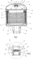
- FIG. 1 shows a section of a pressure accumulator with an accumulator housing 10 with a gas chamber 12 filled with a working gas and a fluid chamber 14, which are separated from one another in a fluid-tight manner by a movable separating element 16.
- the accumulator housing 10 of the pressure accumulator which is designed rotationally symmetrically to an axis of rotation R, comprises a cover-side closing part 18 and a tubular-cylindrical main part 20 with a base 21.
- the closing part 18 and the main part 20 are welded to one another at a narrow, circumferential fastening surface 22.
- the gas chamber 12 is arranged in the part of the accumulator housing 10 associated with the closing part 18 .
- In the area of the connection of the closing part 18 to the main part 20 there is an annular insert part 24 with a horizontal first section 26 and a vertical second section 28 directed towards the fluid space 14 .
- the vertical direction is defined by the axis of rotation R of the accumulator.
- the first section 26 forms an upper fastening point for the separating element 16 designed as a bellows.
- the lower end of the separating element 16 is fastened to a plate part 30 which is movably arranged inside the pressure accumulator and has a circular cross-section corresponding to the inner cross-section of the accumulator housing 10. in the in 1
- the separating element 16 has the maximum extent in the axial direction and the plate part 30 is arranged close to the bottom 21 of the accumulator housing 10 .
- a plurality of guides 34 directed towards the inner wall of the accumulator housing 10 are formed on the edge section 32 and facilitate an unobstructed axial movement of the plate part 30 in the pressure accumulator.
- the base 21 of the accumulator housing 10 is adjoined by an extension-like connection body 36 in which a fluid connection 38 opening into the fluid chamber 14 is formed.
- a fluid connection 38 opening into the fluid chamber 14 is formed in order to connect the fluid connection 38 with an in 1
- an external thread 40 is formed at the lower end of the connector body 36, which otherwise serves to connect a fluid line, not shown, to which the bellows accumulator can be connected.
- a filling connection 44 sealed in a gas-tight manner with a socket 42 for filling the gas chamber 12 is formed in the cover-side closing part 18 of the accumulator housing 10 .
- a central component of the pressure accumulator is a monitoring device 46 which is introduced rotationally symmetrically to the axis of symmetry R in an extension of the cover-side closing part 18 which projects into the interior of the accumulator housing 10 .
- the monitoring device 46 provides an optically recognizable indication in the event of a fault affecting the sealing effect of the separating element 16, in which fluid passes from the fluid space 14 into the gas space 12.
- the monitoring device 46 has an indicator which is accommodated in a capsule 48 and which noticeably changes its optical properties when cross-linked with the fluid which is undesirable in the gas space 12 .
- a capsule wall 50 is permeable for the passage of the fluid.
- a viewing window 54 is arranged at the outside end of the monitoring device 46, which is arranged in a through hole 52 in the closing part 18, for observing the indicator and a change in its optical properties.
- the viewing window 54 is preferably off a shatterproof sight glass and gives a view of the capsule 48 from the outside.
- a screen body 56 is arranged on the inside end of the monitoring device 46 assigned to the separating element 16. The capsule 48 with the indicator changing its optical properties is arranged between the viewing window 54 and the separating element 16 in the storage housing 10 and is held in its position by the screen body 56 .
- the capsule 48 accommodates a flat pad 60 (cushion) in its interior, which in turn accommodates the indicator and is a fleece, preferably a glass fiber fleece, or a glass fabric, in particular a glass fiber fabric.
- the indicator is a reagent accommodated in the pad 60, which changes its optical properties when it comes into contact with the fluid, preferably starting from a neutral color and leading to a visible color change with the formation of a signal color.
- the indicator is preferably selected from the group of (diethylamino)benzo[a]phenoxazines, which causes a color change to the signal color red.
- the capsule wall 50 for the passage of the fluid is provided with openings 80, 82 (cf. 3 ) Mistake.
- a receptacle 62 for the fluid exiting at the top of the pad 60 is formed above the capsule 48 .
- the receiving trough 62 is covered by a cover part 64 that curves upwards and that, when kept transparent, allows a view from the viewing window 54 at least of the contents of the trough.
- the cover part 64 is provided with optical properties such as prismatic properties, a coating or an enlargement, Mistake. This enables the observation of an optically changed, preferably discolored fluid on the upper side of the capsule 58 in a simple and reliable manner, which indicates a malfunction due to a defect in the separating element 16 . The color change to a signal color can be clearly observed through the viewing window 54, even in daylight.
- the monitoring device 46 enables a non-destructive, tool-free visual inspection of the separating element 16 arranged in the storage housing 10 during operation and during maintenance.
- the indicator surface is significantly enlarged, which leads to improved recognition of the color change compared to known solutions.
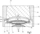
- 3 shows in detail the configuration of the capsule 48, in particular as part of the monitoring device 46, which is held stationary by the screen body 56, for example in the through hole 52 of a closing part 18 or a different type of component.
- the capsule 48 has a lower capsule shell 66 and an upper capsule shell 68 which are arranged parallel to one another in the central main part of the capsule 48 and enclose the pad 60 and are placed against one another in the edge region 70 .
- the two capsule shells 66, 68 fix a lower fluid-permeable protective layer 72 and an upper fluid-permeable protective layer 74 between them.
- the pad 60 is accommodated between the two fluid-permeable protective layers 72, 74.
- the lower capsule shell 66 is wider than the upper capsule shell 68 and its lateral edge is bent upwards. In this way, the lower capsule shell 66 projects beyond the upper capsule shell 68 to form the receiving trough 62 .
- the lateral edge of the lower capsule shell 68 forms a trough rim 76 which serves as a support for the cover part 64 for spanning the receiving trough 62 .
- the viewing window 54 adjoins the cover part 64 , a narrow intermediate space 78 remaining between the cover part 64 and the viewing window 54 . It is also conceivable that the viewing window 54 to be arranged flat against the cover part 64 with the elimination of the intermediate space 78 . It is also conceivable to integrate the optical properties set by the cover part 64 into the viewing window 54 , for example to provide a coating on the lower side assigned to the capsule 48 and to place the viewing window 54 directly on the rim 76 of the tub.
- a plurality of passages 80 and 82 are formed in the two capsule shells 66, 68, each of which allows passage of the fluid with or without an indicator.
- a gas space 12 (cf. 1 )
- the fluid enters the capsule 48.
- the fluid reaches the pad 60 with the indicator accommodated therein.
- the fluid changes its optical properties and advantageously assumes a signal color such as red.
- the fluid reaches the receiving trough 62 as it spreads further through the upper fluid-permeable protective layer 74 and the further passages 82 in the upper capsule shell 68.
- the discolored fluid as the trough contents can be seen through the transparent viewing window 54 and the cover part 64, which is held transparent clearly recognizable to an observer as a signal for an accident.
- the solution according to the invention is not limited to the use of bellows accumulators, but can be used for all types of pressure accumulators, such as piston, bladder, diaphragm accumulators, in which a movable separating element separates a gas working space from a fluid space.
Landscapes
- Engineering & Computer Science (AREA)
- Physics & Mathematics (AREA)
- Fluid Mechanics (AREA)
- Mechanical Engineering (AREA)
- General Engineering & Computer Science (AREA)
- General Physics & Mathematics (AREA)
- Measuring Fluid Pressure (AREA)
- Supply Devices, Intensifiers, Converters, And Telemotors (AREA)
Description
- Die Erfindung betrifft einen Druckspeicher mit einem Speichergehäuse, in dem ein bewegbares Trennelement einen mit einem Arbeitsgas befüllten Gasraum von einem Fluidraum fluiddicht voneinander trennt, wobei eine Überwachungseinrichtung vorgesehen ist, die bei einem die Abdichtwirkung des Trennelements beeinträchtigenden Störfall eine optisch erkennbare Anzeige liefert und die ein Sichtfenster aufweist, durch das ein Indikator beobachtbar ist, der mit dem Gasraum in Verbindung steht und dessen optische Eigenschaften sich bei Benetzung mit dem Fluid erkennbar ändern.
-
WO 2015/183933 A1 beschreibt einen Druckspeicher mit einem Speichergehäuse, in dem ein bewegbares Trennelement einen mit einem Arbeitsgas befüllten Gasraum von einem Fluidraum fluiddicht voneinander trennt, wobei eine Überwachungseinrichtung vorgesehen ist, die bei einem die Abdichtwirkung des Trennelements beeinträchtigenden Störfall eine optisch erkennbare Anzeige liefert und die ein Sichtfenster aufweist, durch das ein Indikator beobachtbar ist, der mit dem Gasraum in Verbindung steht und dessen optische Eigenschaften sich bei Benetzung mit dem Fluid erkennbar ändern. - Weiterer Stand der Technik ist in
US 3 502 436 A ,JP 2011 215076 A US 4 201 080 A ,US 3 067 012 A undUS 4 063 452 A beschrieben. - Ein derartiger Druckspeicher ist beispielsweise aus
WO 2015/113731 A1 bekannt. Durch die Überwachungseinrichtung kann die Funktionsfähigkeit des Druckspeichers bei laufendem Betrieb des Systems überprüft werden, ohne dass der Druckspeicher aus dem System herausgenommen und einer externen Funktionsprüfung unterzogen werden müsste. Vorteilhafterweise ist als Indikator eine Probenmenge an spezieller Glasfaserwolle vorgesehen, die im unbenetzten Zustand weiß ist und bei Benetzung mit Fluiden unterschiedlicher Art sich visuell erkennbar verfärbt. Die Glasfaserwolle ist in einer durch die Wand des Gehäuses zum Gasraum führenden Bohrung zwischen einem das Sichtfenster aufweisenden Gewindeeinsatz und einem Siebkörper am inneren Ende der Bohrung angeordnet. Hinsichtlich der möglichen guten Erkennbarkeit des Indikators nach Anzeige eines Störfalls sowie einer vereinfachten Handhabung und eines bauraumsparenden Aufbaus lässt die bekannte Lösung noch Wünsche offen. - Der Erfindung liegt die Aufgabe zugrunde, die Erkennbarkeit und die Handhabung eines Indikators als Teil einer Überwachungseinrichtung zu vereinfachen sowie einen bauraumsparenden Aufbau zu ermöglichen.
- Diese Aufgabe wird gelöst durch einen Druckspeicher mit den Merkmalen des Patentanspruchs 1 in seiner Gesamtheit. Ein erfindungsgemäßer Druckspeicher ist dadurch gekennzeichnet, dass der seine optischen Eigenschaften ändernde Indikator in einer Kapsel aufgenommen ist, deren Kapselwand für den Durchtritt des Fluids durchlässig ist und die zwischen dem Sichtfenster und dem Trennelement im Speichergehäuse angeordnet ist.
- Durch die Aufnahme des Indikators in einer Kapsel ist ein kompaktes Bauteil geschaffen, welches in einfacher und bauraumsparender Weise gelagert und transportiert werden kann. Der Einbau, der Ausbau und ein möglicher Wechsel der Kapsel in der Überwachungseinrichtung sind jeweils in wenigen Schritten durchführbar. Die Kapsel ist lose oder ortsfest in Bezug zum Speichergehäuse zwischen dem Sichtfenster und dem Trennelement angeordnet. Dies ermöglicht einen bauraumsparenden Aufbau der gesamten Überwachungseinrichtung, da die Kapsel mit dem darin aufgenommenen Indikator eine geringe Bauhöhe hat. Vorteilhafterweise weist die Kapsel eine flache Grundform auf mit einer größtmöglichen Kapselwand für den Durchtritt des zu detektierenden Fluids. Zur Anordnung in einer Bohrung im Speichergehäuse weist die Kapsel zweckmäßigerweise eine kreisförmige Grundform auf. In praktischen Versuchen hat es sich erwiesen, dass aufgrund der Kapselgestaltung auch eine bessere Erkennbarkeit für den Indikator geschaffen ist gegenüber der bekannten Lösung mit der Glaswolle.
- Bei einer bevorzugten Ausführungsform des erfindungsgemäßen Druckspeichers weist die Kapsel in ihrem Inneren ein Pad (Kissen) auf, das den Indikator aufnimmt und das zwischen mindestens einer fluiddurchlässigen Schutzlage aufgenommen ist. Durch die mindestens eine Schutzlage werden mögliche Beschädigungen des Pads durch einen Kontakt mit der Innenwand der Kapsel wirksam vermieden. Die Kapsel umschließt das Pad, welches vorzugsweise aus einem Vlies gebildet ist, vorteilhafterweise nahezu abstandsfrei. Insoweit schützt die jeweilige Schutzlage auch davor, dass ungewollt das Pad aus der Kapsel ausgetragen wird.
- Bei einer weiteren bevorzugten Ausführungsform des erfindungsgemäßen Druckspeichers weist die Kapsel einen in Richtung des Sichtfensters vorstehenden, umlaufenden Wannenrand auf zwecks Aufnahme von in dem Fluid gelösten und/oder dispergierten Indikator, der aus Durchlässen in der oberen Kapselschale der Kapsel austritt, und dass Durchlässe in der unteren Kapselschale den Durchtritt des Fluids in die Kapsel mit dem Pad ermöglichen. Das in die Überwachungseinrichtung mit der darin angeordneten Kapsel einströmende Fluid erreicht nach Durchtritt der unteren Kapselschale das Pad und nach Durchtritt der oberen Kapselschale die sich daran anschließende Aufnahmewanne, was einen funktionssicheren Betrieb ermöglicht.
- Sobald ein Störfall durch eine Reaktion mit dem Indikator detektiert wird, weist das an der oberen Kapselschale austretende Fluid die Farbe entsprechend der bei Benetzung mit dem Fluid geänderten optischen Eigenschaften des Indikators auf. Von Vorteil ist hier eine Signalfarbe, welche eine große Leuchtkraft besitzt und von einer Bedienperson durch das Sichtfenster hindurch gut erkennbar ist. Hierbei ist zu berücksichtigen, dass das Innere des Speichergehäuses unbeleuchtet ist, weshalb die Kapsel mit dem darin aufgenommenen Indikator vorzugsweise räumlich nahe zum Sichtfenster angeordnet ist. Dies ermöglicht die Nutzung von von außen einfallendem Licht zur Beobachtung eines Signals im Störfall.
- Bei einer bevorzugten Ausführungsform des erfindungsgemäßen Druckspeichers ist der Wannenrand der Kapsel aus einem seitlichen Rand der unteren Kapselschale gebildet, der über die obere Kapselschale unter Bildung einer Aufnahmewanne axial vorsteht. Der in Richtung des Sichtfensters vorstehende Wannenrand erlaubt die Auflage einer durchsichtigen Abdeckung, welche einerseits die Wanne als Raum für das an der oberen Kapselschale der Kapsel austretende Fluid abschließt und andererseits eine Beobachtung des Fluids ermöglicht. Es ist auch denkbar, das Sichtfenster unmittelbar an den Wannenrand der Kapsel anschließend anzuordnen. Die über die obere Kapselschale axial vorstehende untere Kapselschale umgreift diese in der Art einer Klammer entlang des kompletten Außenrandes und dient vorzugsweise zudem einer sicheren Aneinanderlage der beiden Kapselschalen. Die genannte Abdeckung nebst Wanne verhindern ein ungewolltes Verflüchtigen der Indikatorsubstanz aus der Überwachungseinrichtung.
- Weiter ist vorteilhaft, dass die Aufnahmewanne von einem Deckelteil überspannt ist, der durchsichtig gehalten den Blick von dem Sichtfenster zumindest auf den Wanneninhalt freigibt. Das vom Indikator kommend aus der Kapsel in die Wanne strömende Fluid kann durch das Deckelteil hindurch überwacht und eine Änderung seiner optischen Eigenschaften, wie ein Farbumschlag unter Bildung einer Signalfarbe, als Signal für einen Störfall erkannt werden.
- Besonders bevorzugt ist das Deckelteil mit optischen Eigenschaften, wie prismatischen Eigenschaften, einer Beschichtung oder einer Vergrößerung versehen. Die optischen Eigenschaften des Deckelteils sind anforderungsgerecht gewählt, um eine Beobachtung des Wanneninhalts durch das Deckelteil hindurch zu erleichtern. Neben einer Vergrößerung ist insbesondere die Verstärkung von Kontrasten zur Erkennung einer Änderung der optischen Eigenschaften des Fluids von Vorteil, wozu auch eine etwaige Beschichtung mit beiträgt.
- Bei einer bevorzugten Ausführungsform des erfindungsgemäßen Druckspeichers ist das Sichtfenster aus einem Schauglas gebildet, das in ein deckelseitiges Abschlussteil des Speichergehäuses eingebracht ist und den Blick von außen auf die Kapsel als zentralem Bestandteil der Überwachungseinrichtung freigibt. Zweckmäßigerweise ist das Schauglas am äußeren Ende einer Bohrung im Speichergehäuse respektive Abschlussteil angeordnet, besonders bevorzugt mit einem Innengewinde der Bohrung verschraubt oder verklebt.
- Bei einer weiteren bevorzugten Ausführungsform des erfindungsgemäßen Druckspeichers sind das Deckelteil und die Kapsel mit dem Indikatorpad von einem Siebkörper gehalten, der vonseiten des Trennelements aus in das deckelartige Abschlussteil des Speichergehäuses einsetzbar und insbesondere mittels eines Schraubeinsatzes auf Position gehalten ist. Die einzelnen Komponenten der Überwachungseinrichtung lassen sich auf diese Weise einfach und kompakt in einen Bauraum, wie das Innere einer im Abschlussteil eingebrachten Bohrung, einsetzen. Besonders bevorzugt ist der Schraubeinsatz zur Lagefixierung des Siebkörpers am unteren Ende der Bohrung angeordnet. Vorteilhafterweise sind die Komponenten rotationssymmetrisch zur Symmetrieachse der Bohrung ausgebildet und angeordnet.
- Entlang der axialen Erstreckung der Bohrung sind nacheinander von außen nach innen das Sichtfenster, das Deckelteil, die Kapsel mit dem Indikator und der Siebkörper angeordnet. Der Siebkörper ermöglicht einen Fluiddurchtritt des zu detektierenden Mediums zur Kapsel mit dem Indikatorpad. Anstelle des Siebkörpers kann auch ein fluiddurchlässiges Membranteil eingesetzt werden.
- Bei einer weiteren bevorzugten Ausführungsform der Erfindung führt der Indikator bei Berührung mit dem Fluid, ausgehend von einer Neutralfarbe, zu einem sichtbaren Farbumschlag unter Bildung einer Signalfarbe und der Indikator ist aus der Stoffgruppe der (Diethylamino)benzo[a]phenoxazine ausgewählt. Durch den Farbumschlag von der Neutralfarbe zur Signalfarbe, welche in einem deutlichen Farbkontrast zur Neutralfarbe steht, wird ein Warnsignal für einen von der Überwachungseinrichtung festgestellten Störfall erzeugt. Beispielsweise kann ein Farbumschlag von Weiß zu Rot, Grün oder Blau stattfinden. Aufgrund des Farbumschlages hin zu einer auffälligen Farbe mit Signalwirkung ist der durch den chemischen Indikator angezeigte Störfall von einer Bedienperson kaum zu übersehen. Besonders bevorzugt ist die Molekülformel des chemischen Indikators C20H18N2O2. Dieses auch den chemischen Namen "Nil Red" tragende Reagenz erzeugt bei einer Reaktion mit dem zugehörigen zu detektierenden Medium die nicht zu übersehende Signalfarbe Rot.
- Weiter ist vorteilhaft, dass das Pad für den Indikator ein Vlies, vorzugsweise ein Glasfaservlies, oder ein Glasfasergewebe, insbesondere ein Glasseidengewebe, ist. Ein Vlies (non-woven) oder auch eine Watte weist in der Regel die Neutralfarbe Weiß auf, so dass bei Verwendung eines chemischen Indikators wie "Nil Red" oder dergleichen ein gut sichtbarer Farbumschlag unter Bildung der Signalfarbe Rot gewährleistet ist. Des Weiteren lässt sich ein Pad in einfacher Weise aus einem Vlies oder Glasfasergewebe in besonders günstiger Weise, herstellen.
- Weitere Vorteile und Merkmale der Erfindung ergeben sich aus den Figuren und der nachfolgenden Beschreibung der Zeichnung. Die vorstehend genannten und die weiter angeführten Merkmale können erfindungsgemäß jeweils einzeln oder in beliebigen Kombinationen an einem erfindungsgemäßen Druckspeicher realisiert sein. Die in den Figuren gezeigten Merkmale sind rein schematisch und nicht maßstäblich zu verstehen. Es zeigen:
- Fig. 1
- ein Ausführungsbeispiel des erfindungsgemäßen Druckspeichers, gezeigt im Schnitt;
- Fig. 2
- eine vergrößerte Darstellung der im Druckspeicher aus
Fig. 1 angeordneten Überwachungseinrichtung; und - Fig. 3
- einen vergrößerten Teilbereich einer beispielhaften, erfindungsgemäßen Überwachungseinrichtung zur Veranschaulichung des Aufbaus der Kapsel mit dem darin aufgenommenen Indikatorpad.
-
Fig. 1 zeigt im Schnitt einen Druckspeicher mit einem Speichergehäuse 10 mit einem mit einem Arbeitsgas befüllten Gasraum 12 und einem Fluidraum 14, die über ein bewegbares Trennelement 16 fluiddicht voneinander getrennt sind. Das Speichergehäuse 10 des rotationssymmetrisch zu einer Rotationsachse R ausgebildeten Druckspeichers umfasst ein deckelseitiges Abschlussteil 18 und ein rohrzylinderförmiges Hauptteil 20 mit einem Boden 21. Das Abschlussteil 18 und das Hauptteil 20 sind an einer umlaufenden, schmalen Befestigungsfläche 22 miteinander verschweißt. Der Gasraum 12 ist in dem dem Abschlussteil 18 zugeordneten Teil des Speichergehäuses 10 angeordnet. Im Bereich der Verbindung des Abschlussteils 18 mit dem Hauptteil 20 ist ein ringförmiges Einsatzteil 24 mit einem horizontalen ersten Abschnitt 26 und einem zum Fluidraum 14 gerichteten vertikalen zweiten Abschnitt 28 vorgesehen. - Die vertikale Richtung ist durch die Rotationsachse R des Druckspeichers vorgegeben. Der erste Abschnitt 26 bildet eine obere Befestigungsstelle für das als Faltenbalg ausgebildete Trennelement 16. Das untere Ende des Trennelements 16 ist an einem Plattenteil 30 befestigt, welches im Inneren des Druckspeichers bewegbar angeordnet ist und dem inneren Querschnitt des Speichergehäuses 10 entsprechend einen kreisförmigen Querschnitt aufweist. In dem in
Fig. 1 gezeigten unbenutzten Zustand des Druckspeichers weist das Trennelement 16 die maximale Erstreckung in axialer Richtung auf und das Plattenteil 30 ist nahe zum Boden 21 des Speichergehäuses 10 angeordnet. In einem Randabschnitt 32 des Plattenteils 30 weist dieses eine etwas größere Dicke gegenüber dem Hauptteil in der Mitte auf. Am Randabschnitt 32 sind mehrere zur Innenwand des Speichergehäuses 10 gerichtete Führungen 34 ausgebildet, die eine hemnisfreie axiale Bewegung des Plattenteils 30 im Druckspeicher erleichtern. - An den Boden 21 des Speichergehäuses 10 schließt sich ein fortsatzartiger Anschlusskörper 36 an, in welchem ein in den Fluidraum 14 mündender Fluidanschluss 38 ausgebildet ist. Um den Fluidanschluss 38 mit einer in
Fig. 1 nicht gezeigten Schraubkappe zu verschließen, ist am unteren Ende des Anschlusskörpers 36 ein Außengewinde 40 ausgebildet, das ansonsten dem Anschluss einer nicht dargestellten Fluidleitung dient, an die der Balgspeicher anschließbar ist. Im deckelseitigen Abschlussteil 18 des Speichergehäuses 10 ist versetzt zur Rotationsachse R ein mit einem Stutzen 42 gasdicht verschlossener Füllanschluss 44 zur Befüllung des Gasraumes 12 ausgebildet. - Zentraler Bestandteil des Druckspeichers ist eine Überwachungseinrichtung 46, die rotationssymmetrisch zur Symmetrieachse R in einen ins Innere des Speichergehäuses 10 ragenden Fortsatz des deckelseitigen Abschlussteils 18 eingebracht ist. Die Überwachungseinrichtung 46 liefert bei einem die Abdichtwirkung des Trennelements 16 beeinträchtigenden Störfall, in welchem Fluid aus dem Fluidraum 14 in den Gasraum 12 übertritt, eine optische erkennbare Anzeige. Hierfür weist die Überwachungseinrichtung 46 einen in eine Kapsel 48 aufgenommenen Indikator auf, der bei Vernetzung mit dem im Gasraum 12 unerwünschten Fluid seine optischen Eigenschaften erkennbar ändert. Eine Kapselwand 50 ist für den Durchtritt des Fluids durchlässig ausgebildet.
- Zur Beobachtung des Indikators sowie einer Änderung seiner optischen Eigenschaften ist am außenseitigen Ende der Überwachungseinrichtung 46, welche in einer Durchgangsbohrung 52 im Abschlussteil 18 angeordnet ist, ein Sichtfenster 54 angeordnet. Das Sichtfenster 54 ist vorzugsweise aus einem bruchsicheren Schauglas gebildet und gibt den Blick von außen auf die Kapsel 48 frei. Zur Lagefixierung der Kapsel 48 ist am innenseitigen, dem Trennelement 16 zugeordneten Ende der Überwachungseinrichtung 46 ein Siebkörper 56 angeordnet, der von Seiten des Trennelements 16 aus in das deckelartige Abschlussteil 18 eingesetzt und dort mittels eines Schraubeinsatzes 58 auf Position gehalten ist. Die Kapsel 48 mit dem seine optischen Eigenschaften ändernden Indikator ist zwischen dem Sichtfenster 54 und dem Trennelement 16 im Speichergehäuse 10 angeordnet und durch den Siebkörper 56 in seiner Lage gehalten.
-
Fig. 2 zeigt in vergrößerter Darstellung entsprechend dem kreisförmigen Ausschnitt K die Überwachungseinrichtung 46 ausFig. 1 mit dem Sichtfenster 54, der Kapsel 48 und dem Siebkörper 56 samt Schraubeinsatz 58.Fig. 2 verdeutlicht, dass die Kapsel 48 in ihrem Inneren ein flaches Pad 60 (Kissen) aufnimmt, dass wiederum den Indikator aufnimmt und ein Vlies, vorzugsweise ein Glasfaservlies, oder ein Glasgewebe, insbesondere ein Glasseidengewebe, ist. Der Indikator ist ein in das Pad 60 aufgenommenes Reagenz, welches bei Berührung mit dem Fluid seine optischen Eigenschaften ändert, vorzugsweise ausgehend von einer Neutralfarbe zu einem sichtbaren Farbumschlag unter Bildung einer Signalfarbe führt. Vorzugsweise ist der Indikator aus der Stoffgruppe der (Diethylamino)benzo[a]phenoxazine ausgewählt, was einen Farbumschlag zur Signalfarbe Rot bewirkt. Um einen Kontakt des Pads 60 und eine Reaktion des Indikators mit dem zu detektierenden Fluid zu ermöglichen, ist die Kapselwand 50 für den Durchtritt des Fluids mit Durchlässen 80, 82 (vgl.Fig. 3 ) versehen. - Oberhalb der Kapsel 48 ist eine Aufnahmewanne 62 für das an der Oberseite des Pads 60 austretende Fluid ausgebildet. Die Aufnahmewanne 62 ist von einem nach oben gewölbten Deckelteil 64 überspannt, der durchsichtig gehalten den Blick von dem Sichtfenster 54 zumindest auf den Wanneninhalt freigibt. Das Deckelteil 64 ist mit optischen Eigenschaften, wie prismatischen Eigenschaften, einer Beschichtung oder einer Vergrößerung, versehen. Dies ermöglicht in einfacher und zuverlässiger Weise die Beobachtung eines optisch veränderten, vorzugsweise verfärbten Fluids an der Oberseite der Kapsel 58, was einen Störfall aufgrund eines Defektes am Trennelement 16 anzeigt. Der Farbumschlag zu einer Signalfarbe hin ist durch das Sichtfenster 54 hindurch deutlich, auch bei Tageslicht, beobachtbar. Die Überwachungseinrichtung 46 ermöglicht eine zerstörungsfreie, werkzeuglose Sichtprüfung des im Speichergehäuse 10 angeordneten Trennelements 16 im laufenden Betreib sowie während einer Wartung. Insbesondere durch die Wannengestaltung der Kapsel 48 in ihrem oberen Bereich ist die Indikatorfläche deutlich vergrößert, was zu einer verbesserten Erkennbarkeit des Farbumschlages gegenüber bekannten Lösungen führt.
Fig. 3 zeigt im Detail die Ausgestaltung der Kapsel 48 insbesonders als Teil der Überwachungseinrichtung 46, welche vom Siebkörper 56 beispielsweise in der Durchgangsbohrung 52 eines Abschlussteils 18 oder eines andersartigen Bauteils ortsfest gehalten ist. Die Kapsel 48 weist eine untere Kapselschale 66 und eine obere Kapselschale 68 auf, die im mittleren Hauptteil der Kapsel 48 parallel zueinander angeordnet das Pad 60 umschließen und im Randbereich 70 aneinandergelegt sind. Im Randbereich 70 fixieren die beiden Kapselschalen 66, 68 zwischen sich eine untere fluiddurchlässige Schutzlage 72 und eine obere fluiddurchlässige Schutzlage 74. Zwischen den beiden fluiddurchlässigen Schutzlagen 72, 74 ist das Pad 60 aufgenommen. Die untere Kapselschale 66 ist gegenüber der oberen Kapselschale 68 verbreitert und mit ihrem seitlichen Rand nach oben gebogen. Auf diese Weise steht die untere Kapselschale 66 über die obere Kapselschale 68 unter Bildung der Aufnahmewanne 62 vor. Der seitliche Rand der unteren Kapselschale 68 bildet einen Wannenrand 76, der als Auflage für das Deckelteil 64 zum Überspannen der Aufnahmewanne 62 dient. An das Deckelteil 64 schließt sich das Sichtfenster 54 an, wobei zwischen dem Deckelteil 64 und dem Sichtfenster 54 ein schmaler Zwischenraum 78 verbleibt. Es ist auch vorstellbar, das Sichtfenster 54 unter Wegfall des Zwischenraumes 78 flächig anliegend am Deckelteil 64 anzuordnen. Weiter ist denkbar, die durch das Deckelteil 64 eingestellten optischen Eigenschaften in das Sichtfenster 54 zu integrieren, beispielsweise an der unteren, der Kapsel 48 zugeordneten Seite eine Beschichtung vorzusehen und das Sichtfenster 54 direkt auf den Wannenrand 76 aufzusetzen. - In den beiden Kapselschalen 66, 68 sind jeweils eine Vielzahl von Durchlässen 80 und 82 ausgebildet, welche jeweils einen Durchtritt des Fluids ohne bzw. mit Indikator ermöglichen. Im Falle eines Störfalls erreicht beispielsweise von einem Gasraum 12 (vgl.
Fig. 1 ) kommend das Fluid durch den Siebkörper 56 hindurch die Kapsel 48. Durch die Durchlässe 80 in der unteren Kapselschale 66 und die untere fluiddurchlässige Schutzlage 72 hindurch erreicht das Fluid das Pad 60 mit dem darin aufgenommenen Indikator. Durch Reaktion mit dem Indikator ändert das Fluid seine optischen Eigenschaften und nimmt vorteilhafterweise eine Signalfarbe, wie Rot, an. Vom Pad 60 aus erreicht das Fluid bei weiterer Ausbreitung durch die obere fluiddurchlässige Schutzlage 74 und die weiteren Durchlässe 82 in der oberen Kapselschale 68 hindurch die Aufnahmewanne 62. Das verfärbte Fluid als Wanneninhalt ist durch das transparente Sichtfenster 54 und das durchsichtig gehaltene Deckelteil 64 hindurch von einem Beobachter deutlich als Signal für einen Störfall erkennbar. - Die erfindungsgemäße Lösung ist nicht auf die Verwendung von Balgspeichern eingeschränkt, sondern kann für alle Arten von Druckspeichern, wie beispielsweise Kolben-, Blasen-, Membranspeichern, eingesetzt werden, bei denen ein bewegbares Trennelement einen Gas- Arbeitsraum von einem Fluidraum separiert.
Claims (10)
- Druckspeicher mit einem Speichergehäuse (10), in dem ein bewegbares Trennelement (16) einen mit einem Arbeitsgas befüllten Gasraum (12) von einem Fluidraum (14) fluiddicht voneinander trennt, wobei eine Überwachungseinrichtung (46) vorgesehen ist, die bei einem die Abdichtwirkung des Trennelements (16) beeinträchtigenden Störfall eine optisch erkennbare Anzeige liefert und die ein Sichtfenster (54) aufweist, durch das ein Indikator beobachtbar ist, der mit dem Gasraum (12) in Verbindung steht und dessen optische Eigenschaften sich bei Benetzung mit dem Fluid erkennbar ändern, dadurch gekennzeichnet, dass der seine optischen Eigenschaften ändernde Indikator in einer Kapsel (48) aufgenommen ist, deren Kapselwand (50) für den Durchtritt des Fluids durchlässig ist und die zwischen dem Sichtfenster (54) und dem Trennelement (16) im Speichergehäuse (10) angeordnet ist.
- Druckspeicher nach Anspruch 1, dadurch gekennzeichnet, dass die Kapsel (48) in ihrem Inneren ein Pad (60) aufweist, das den Indikator aufnimmt und das zwischen mindestens einer fluiddurchlässigen Schutzlage (72, 74) aufgenommen ist.
- Druckspeicher nach Anspruch 2, dadurch gekennzeichnet, dass die Kapsel (48) einen in Richtung des Sichtfensters (54) vorstehenden, umlaufenden Wannenrand (76) aufweist zwecks Aufnahme von in dem Fluid gelösten und/oder dispergierten Indikator, der aus Durchlässen (82) in der oberen Kapselschale (68) der Kapsel (48) austritt, und dass Durchlässe (80) in der unteren Kapselschale (66) den Durchtritt des Fluids in die Kapsel (48) mit dem Pad (60) ermöglichen.
- Druckspeicher nach Anspruch 3, dadurch gekennzeichnet, dass der Wannenrand (76) der Kapsel (48) aus einem seitlichen Rand der unteren Kapselschale (66) gebildet ist, der über die obere Kapselschale (68) unter Bildung einer Aufnahmewanne (62) axial vorsteht.
- Druckspeicher nach Anspruch 4, dadurch gekennzeichnet, dass die Aufnahmewanne (62) von einem Deckelteil (64) überspannt ist, der durchsichtig gehalten den Blick von dem Sichtfenster (54) zumindest auf den Wanneninhalt freigibt.
- Druckspeicher nach Anspruch 5, dadurch gekennzeichnet, dass das Deckelteil (64) mit optischen Eigen-schaften, wie prismatischen Eigenschaften, einer Beschichtung oder einer Vergrößerung versehen ist.
- Druckspeicher nach einem der vorstehenden Ansprüche, dadurch gekennzeichnet, dass das Sichtfenster (54) aus einem Schauglas gebildet ist, das in ein deckelseitiges Abschlussteil (18) des Speichergehäuses (10) eingebracht ist und den Blick von außen auf die Kapsel (48) freigibt.
- Druckspeicher nach einem der Ansprüche 5 bis 6 und Anspruch 7, dadurch
gekennzeichnet, dass das Deckelteil (64) und die Kapsel (48) mit dem Indikatorpad (60) von einem Siebkörper (56) gehalten sind, der vonseiten des Trennelements (16) aus in das deckelartige Abschlussteil (18) des Speichergehäuses (10) einsetzbar und insbesondere mittels eines Schraubeinsatzes (58) auf Position gehalten ist. - Druckspeicher nach einem der vorstehenden Ansprüche, dadurch gekennzeichnet, dass der Indikator bei Berührung mit dem Fluid, ausgehend von einer Neutralfarbe, zu einem sichtbaren Farbumschlag unter Bildung einer Signalfarbe führt und er aus der Stoffgruppe der (Diethylamino)benzo[a]phenoxazine ausgewählt ist.
- Druckspeicher nach einem der Ansprüche 2 bis 6, 8, dadurch
gekennzeichnet, dass das Pad (60) für den Indikator ein Vlies, vorzugsweise ein Glasfaservlies, oder ein Glasfasergewebe, insbesondere ein Glasseidengewebe, ist.
Applications Claiming Priority (2)
| Application Number | Priority Date | Filing Date | Title |
|---|---|---|---|
| DE102018002315.0A DE102018002315A1 (de) | 2018-03-19 | 2018-03-19 | Druckspeicher mit einer Überwachungseinrichtung |
| PCT/EP2019/055953 WO2019179800A1 (de) | 2018-03-19 | 2019-03-11 | Druckspeicher mit einer überwachungseinrichtung |
Publications (3)
| Publication Number | Publication Date |
|---|---|
| EP3735538A1 EP3735538A1 (de) | 2020-11-11 |
| EP3735538B1 true EP3735538B1 (de) | 2023-07-19 |
| EP3735538C0 EP3735538C0 (de) | 2023-07-19 |
Family
ID=65729361
Family Applications (1)
| Application Number | Title | Priority Date | Filing Date |
|---|---|---|---|
| EP19710394.8A Active EP3735538B1 (de) | 2018-03-19 | 2019-03-11 | Druckspeicher mit einer überwachungseinrichtung |
Country Status (6)
| Country | Link |
|---|---|
| US (1) | US11268541B2 (de) |
| EP (1) | EP3735538B1 (de) |
| JP (1) | JP7307740B2 (de) |
| CN (1) | CN111868392B (de) |
| DE (1) | DE102018002315A1 (de) |
| WO (1) | WO2019179800A1 (de) |
Families Citing this family (3)
| Publication number | Priority date | Publication date | Assignee | Title |
|---|---|---|---|---|
| CN113107051A (zh) * | 2021-05-12 | 2021-07-13 | 华能上海燃机发电有限责任公司 | 一种可监测皮囊状态的消防稳压水箱 |
| DE102021003898A1 (de) * | 2021-07-28 | 2023-02-02 | Hydac Technology Gmbh | Druckspeicher |
| CN118641117B (zh) * | 2024-05-29 | 2025-06-24 | 无锡中策波纹管有限公司 | 一种可对膨胀节各变形状态进行检测的检漏装置 |
Citations (2)
| Publication number | Priority date | Publication date | Assignee | Title |
|---|---|---|---|---|
| US3067015A (en) * | 1960-01-29 | 1962-12-04 | Ray F Lawdermilt | Spoilage indicator for food containers |
| US4063452A (en) * | 1975-06-30 | 1977-12-20 | Minnesota Mining And Manufacturing Company | Method and device for monitoring vapor concentration at a phase interface |
Family Cites Families (24)
| Publication number | Priority date | Publication date | Assignee | Title |
|---|---|---|---|---|
| US1387287A (en) * | 1919-06-26 | 1921-08-09 | Margraf Willy | Weather-indicator |
| US2934954A (en) * | 1955-07-13 | 1960-05-03 | Lennan Lights Inc | Humidity indicating device and low pressure static seal therefor |
| US2918893A (en) * | 1955-11-17 | 1959-12-29 | Clyde A Norton | Leakage indicator for liquid fuel systems |
| US2844026A (en) * | 1956-06-18 | 1958-07-22 | Sporlan Valve Co | Combined moisture and liquid indicators |
| US3100691A (en) * | 1959-03-12 | 1963-08-13 | Henry Valve Co | Liquid indicator with moisture indication means |
| US3000345A (en) * | 1960-02-19 | 1961-09-19 | Mueller Brass Co | Liquid indicator |
| US3142287A (en) * | 1961-12-22 | 1964-07-28 | Henry Valve Co | Refrigerant moisture-liquid indicator assembly and cap unit therefor |
| US3502436A (en) | 1966-12-22 | 1970-03-24 | Gen Motors Corp | Leak visual warning and detection device |
| CA1066141A (en) * | 1975-06-30 | 1979-11-13 | Minnesota Mining And Manufacturing Company | Method and device for monitoring vapor concentration at a phase interface |
| JPS52124383A (en) * | 1976-04-13 | 1977-10-19 | Eishin Kagaku Kk | Leakage inspection agent |
| US4201080A (en) * | 1976-11-24 | 1980-05-06 | Bernard Slepak | Moisture indicator |
| US4793180A (en) * | 1981-10-14 | 1988-12-27 | Agm Cargo-Ties, Inc. | Delayed action irreversible humidity indicator |
| US5383338A (en) * | 1993-12-17 | 1995-01-24 | Emerson Electric Co. | In-line sight indicator |
| US6576473B1 (en) * | 1999-05-28 | 2003-06-10 | Mainstream Engineering Corporation | Removable test kit and method of use for vapor compression systems |
| US7105225B2 (en) * | 2001-10-05 | 2006-09-12 | 3M Innovative Properties Company | Water contract indicator |
| US20030198573A1 (en) * | 2002-01-25 | 2003-10-23 | Illumina, Inc. | Sensor arrays for detecting analytes in fluids |
| WO2011100718A2 (en) * | 2010-02-13 | 2011-08-18 | Mcalister Roy E | Methods, devices, and systems for detecting properties of target samples |
| JP2011215076A (ja) * | 2010-04-01 | 2011-10-27 | Bridgestone Corp | 液漏れ検出シール及び液漏れ検出装置 |
| DE102010027038A1 (de) * | 2010-07-14 | 2012-01-19 | Hydac Filtertechnik Gmbh | Filterelement |
| DE102011100532A1 (de) * | 2011-05-05 | 2012-11-08 | Hydac Technology Gmbh | Medientrennvorrichtung, insbesondere Hydrospeicher einschließlich zugehöriger Messeinrichtung und Messverfahren |
| DE102014001283A1 (de) | 2014-02-01 | 2015-08-06 | Hydac Technology Gmbh | Druckspeicher |
| JP5756207B1 (ja) | 2014-04-18 | 2015-07-29 | 調和工業株式会社 | 油圧ホース用油漏れ防止材及び杭の施工方法 |
| US9915433B2 (en) | 2014-05-30 | 2018-03-13 | Amtrol Licensing Inc. | Moisture detecting air cap indicator for expansion tank failure |
| DE102015012253A1 (de) * | 2015-09-18 | 2017-03-23 | Hydac Technology Gmbh | Balgspeicher, insbesondere Pulsationsdämpfer |
-
2018
- 2018-03-19 DE DE102018002315.0A patent/DE102018002315A1/de not_active Withdrawn
-
2019
- 2019-03-11 US US16/981,784 patent/US11268541B2/en active Active
- 2019-03-11 WO PCT/EP2019/055953 patent/WO2019179800A1/de not_active Ceased
- 2019-03-11 JP JP2020549765A patent/JP7307740B2/ja active Active
- 2019-03-11 CN CN201980018552.6A patent/CN111868392B/zh active Active
- 2019-03-11 EP EP19710394.8A patent/EP3735538B1/de active Active
Patent Citations (2)
| Publication number | Priority date | Publication date | Assignee | Title |
|---|---|---|---|---|
| US3067015A (en) * | 1960-01-29 | 1962-12-04 | Ray F Lawdermilt | Spoilage indicator for food containers |
| US4063452A (en) * | 1975-06-30 | 1977-12-20 | Minnesota Mining And Manufacturing Company | Method and device for monitoring vapor concentration at a phase interface |
Also Published As
| Publication number | Publication date |
|---|---|
| US11268541B2 (en) | 2022-03-08 |
| JP7307740B2 (ja) | 2023-07-12 |
| DE102018002315A1 (de) | 2019-09-19 |
| WO2019179800A1 (de) | 2019-09-26 |
| CN111868392A (zh) | 2020-10-30 |
| EP3735538A1 (de) | 2020-11-11 |
| US20210115948A1 (en) | 2021-04-22 |
| JP2021518512A (ja) | 2021-08-02 |
| EP3735538C0 (de) | 2023-07-19 |
| CN111868392B (zh) | 2023-05-23 |
Similar Documents
| Publication | Publication Date | Title |
|---|---|---|
| EP3099940B1 (de) | Druckspeicher | |
| WO2019179800A1 (de) | Druckspeicher mit einer überwachungseinrichtung | |
| EP2682172A2 (de) | Filtervorrichtung sowie Filterelement für eine dahingehende Filtervorrichtung | |
| DE112009005169B4 (de) | Filter | |
| EP3972712B1 (de) | Filtervorrichtung | |
| DE102009048067A1 (de) | Aufprallsensor mit einem schlauchförmigen Körper | |
| DE112016003727T5 (de) | Mechanische Vorrichtung | |
| EP3784911B1 (de) | Hydrospeicher | |
| DE112012004090T5 (de) | Schmierstofffiltersystem | |
| CH643645A5 (de) | Apparat zum behandeln von komprimiertem gas, insbesondere zum filtrieren von solchem oder zum vermengen von solchem mit einem schmiermittelnebel. | |
| EP0023548A1 (de) | Mehrteiliges Filtergehäuse zur Aufnahme von mehreren patronenförmigen Filterelementen | |
| DE60127367T2 (de) | Entlüftungsventil mit einer Diagnosesöffnung | |
| DE3722562A1 (de) | Ringfoermiger filterkoerper | |
| DE102011113116B3 (de) | Immersionskörper | |
| DE102011081502A1 (de) | Kühlschmiermittelzuführungssystem | |
| EP2827144B1 (de) | Sensorkopf für ein Gasmessgerät | |
| EP2593205B1 (de) | Filterelement | |
| EP0902193A2 (de) | Kolbenspeicher mit Tiefenfiltrationsdichtung | |
| AT505370B1 (de) | Anordnung und verfahren zur optischen überwachung eines druckraums bzw. einer brennkammer | |
| DE102004058863A1 (de) | Adapter zur Elektrolytzufuhr für einen potentiometrischen Sensor | |
| DE202016000191U1 (de) | Zentrifugentrommel zur Blutbehandlung | |
| DE102014114544B4 (de) | Filtrationsvorrichtung | |
| DE102021003898A1 (de) | Druckspeicher | |
| DE10136865A1 (de) | Vorrichtung zur Messung der Chemilumineszenz | |
| DE2509911A1 (de) | Geraet zur kontrolle von in hydraulischen systemen befindlicher hydraulikfluessigkeit |
Legal Events
| Date | Code | Title | Description |
|---|---|---|---|
| STAA | Information on the status of an ep patent application or granted ep patent |
Free format text: STATUS: UNKNOWN |
|
| STAA | Information on the status of an ep patent application or granted ep patent |
Free format text: STATUS: THE INTERNATIONAL PUBLICATION HAS BEEN MADE |
|
| PUAI | Public reference made under article 153(3) epc to a published international application that has entered the european phase |
Free format text: ORIGINAL CODE: 0009012 |
|
| STAA | Information on the status of an ep patent application or granted ep patent |
Free format text: STATUS: REQUEST FOR EXAMINATION WAS MADE |
|
| 17P | Request for examination filed |
Effective date: 20200803 |
|
| AK | Designated contracting states |
Kind code of ref document: A1 Designated state(s): AL AT BE BG CH CY CZ DE DK EE ES FI FR GB GR HR HU IE IS IT LI LT LU LV MC MK MT NL NO PL PT RO RS SE SI SK SM TR |
|
| AX | Request for extension of the european patent |
Extension state: BA ME |
|
| DAV | Request for validation of the european patent (deleted) | ||
| DAX | Request for extension of the european patent (deleted) | ||
| RAP3 | Party data changed (applicant data changed or rights of an application transferred) |
Owner name: HYDAC TECHNOLOGY GMBH |
|
| STAA | Information on the status of an ep patent application or granted ep patent |
Free format text: STATUS: EXAMINATION IS IN PROGRESS |
|
| 17Q | First examination report despatched |
Effective date: 20220215 |
|
| GRAP | Despatch of communication of intention to grant a patent |
Free format text: ORIGINAL CODE: EPIDOSNIGR1 |
|
| STAA | Information on the status of an ep patent application or granted ep patent |
Free format text: STATUS: GRANT OF PATENT IS INTENDED |
|
| INTG | Intention to grant announced |
Effective date: 20230414 |
|
| GRAS | Grant fee paid |
Free format text: ORIGINAL CODE: EPIDOSNIGR3 |
|
| GRAA | (expected) grant |
Free format text: ORIGINAL CODE: 0009210 |
|
| STAA | Information on the status of an ep patent application or granted ep patent |
Free format text: STATUS: THE PATENT HAS BEEN GRANTED |
|
| AK | Designated contracting states |
Kind code of ref document: B1 Designated state(s): AL AT BE BG CH CY CZ DE DK EE ES FI FR GB GR HR HU IE IS IT LI LT LU LV MC MK MT NL NO PL PT RO RS SE SI SK SM TR |
|
| REG | Reference to a national code |
Ref country code: GB Ref legal event code: FG4D Free format text: NOT ENGLISH |
|
| REG | Reference to a national code |
Ref country code: CH Ref legal event code: EP |
|
| REG | Reference to a national code |
Ref country code: DE Ref legal event code: R096 Ref document number: 502019008582 Country of ref document: DE |
|
| REG | Reference to a national code |
Ref country code: IE Ref legal event code: FG4D Free format text: LANGUAGE OF EP DOCUMENT: GERMAN |
|
| U01 | Request for unitary effect filed |
Effective date: 20230814 |
|
| U07 | Unitary effect registered |
Designated state(s): AT BE BG DE DK EE FI FR IT LT LU LV MT NL PT SE SI Effective date: 20230821 |
|
| REG | Reference to a national code |
Ref country code: LT Ref legal event code: MG9D |
|
| PG25 | Lapsed in a contracting state [announced via postgrant information from national office to epo] |
Ref country code: GR Free format text: LAPSE BECAUSE OF FAILURE TO SUBMIT A TRANSLATION OF THE DESCRIPTION OR TO PAY THE FEE WITHIN THE PRESCRIBED TIME-LIMIT Effective date: 20231020 |
|
| PG25 | Lapsed in a contracting state [announced via postgrant information from national office to epo] |
Ref country code: IS Free format text: LAPSE BECAUSE OF FAILURE TO SUBMIT A TRANSLATION OF THE DESCRIPTION OR TO PAY THE FEE WITHIN THE PRESCRIBED TIME-LIMIT Effective date: 20231119 |
|
| PG25 | Lapsed in a contracting state [announced via postgrant information from national office to epo] |
Ref country code: RS Free format text: LAPSE BECAUSE OF FAILURE TO SUBMIT A TRANSLATION OF THE DESCRIPTION OR TO PAY THE FEE WITHIN THE PRESCRIBED TIME-LIMIT Effective date: 20230719 Ref country code: NO Free format text: LAPSE BECAUSE OF FAILURE TO SUBMIT A TRANSLATION OF THE DESCRIPTION OR TO PAY THE FEE WITHIN THE PRESCRIBED TIME-LIMIT Effective date: 20231019 Ref country code: IS Free format text: LAPSE BECAUSE OF FAILURE TO SUBMIT A TRANSLATION OF THE DESCRIPTION OR TO PAY THE FEE WITHIN THE PRESCRIBED TIME-LIMIT Effective date: 20231119 Ref country code: HR Free format text: LAPSE BECAUSE OF FAILURE TO SUBMIT A TRANSLATION OF THE DESCRIPTION OR TO PAY THE FEE WITHIN THE PRESCRIBED TIME-LIMIT Effective date: 20230719 Ref country code: GR Free format text: LAPSE BECAUSE OF FAILURE TO SUBMIT A TRANSLATION OF THE DESCRIPTION OR TO PAY THE FEE WITHIN THE PRESCRIBED TIME-LIMIT Effective date: 20231020 |
|
| PG25 | Lapsed in a contracting state [announced via postgrant information from national office to epo] |
Ref country code: PL Free format text: LAPSE BECAUSE OF FAILURE TO SUBMIT A TRANSLATION OF THE DESCRIPTION OR TO PAY THE FEE WITHIN THE PRESCRIBED TIME-LIMIT Effective date: 20230719 |
|
| REG | Reference to a national code |
Ref country code: DE Ref legal event code: R097 Ref document number: 502019008582 Country of ref document: DE |
|
| PG25 | Lapsed in a contracting state [announced via postgrant information from national office to epo] |
Ref country code: ES Free format text: LAPSE BECAUSE OF FAILURE TO SUBMIT A TRANSLATION OF THE DESCRIPTION OR TO PAY THE FEE WITHIN THE PRESCRIBED TIME-LIMIT Effective date: 20230719 |
|
| PG25 | Lapsed in a contracting state [announced via postgrant information from national office to epo] |
Ref country code: SM Free format text: LAPSE BECAUSE OF FAILURE TO SUBMIT A TRANSLATION OF THE DESCRIPTION OR TO PAY THE FEE WITHIN THE PRESCRIBED TIME-LIMIT Effective date: 20230719 Ref country code: RO Free format text: LAPSE BECAUSE OF FAILURE TO SUBMIT A TRANSLATION OF THE DESCRIPTION OR TO PAY THE FEE WITHIN THE PRESCRIBED TIME-LIMIT Effective date: 20230719 Ref country code: ES Free format text: LAPSE BECAUSE OF FAILURE TO SUBMIT A TRANSLATION OF THE DESCRIPTION OR TO PAY THE FEE WITHIN THE PRESCRIBED TIME-LIMIT Effective date: 20230719 Ref country code: CZ Free format text: LAPSE BECAUSE OF FAILURE TO SUBMIT A TRANSLATION OF THE DESCRIPTION OR TO PAY THE FEE WITHIN THE PRESCRIBED TIME-LIMIT Effective date: 20230719 Ref country code: SK Free format text: LAPSE BECAUSE OF FAILURE TO SUBMIT A TRANSLATION OF THE DESCRIPTION OR TO PAY THE FEE WITHIN THE PRESCRIBED TIME-LIMIT Effective date: 20230719 |
|
| U20 | Renewal fee for the european patent with unitary effect paid |
Year of fee payment: 6 Effective date: 20240402 |
|
| PLBE | No opposition filed within time limit |
Free format text: ORIGINAL CODE: 0009261 |
|
| STAA | Information on the status of an ep patent application or granted ep patent |
Free format text: STATUS: NO OPPOSITION FILED WITHIN TIME LIMIT |
|
| 26N | No opposition filed |
Effective date: 20240422 |
|
| REG | Reference to a national code |
Ref country code: CH Ref legal event code: PL |
|
| PG25 | Lapsed in a contracting state [announced via postgrant information from national office to epo] |
Ref country code: MC Free format text: LAPSE BECAUSE OF FAILURE TO SUBMIT A TRANSLATION OF THE DESCRIPTION OR TO PAY THE FEE WITHIN THE PRESCRIBED TIME-LIMIT Effective date: 20230719 |
|
| PG25 | Lapsed in a contracting state [announced via postgrant information from national office to epo] |
Ref country code: MC Free format text: LAPSE BECAUSE OF FAILURE TO SUBMIT A TRANSLATION OF THE DESCRIPTION OR TO PAY THE FEE WITHIN THE PRESCRIBED TIME-LIMIT Effective date: 20230719 |
|
| PG25 | Lapsed in a contracting state [announced via postgrant information from national office to epo] |
Ref country code: IE Free format text: LAPSE BECAUSE OF NON-PAYMENT OF DUE FEES Effective date: 20240311 |
|
| PG25 | Lapsed in a contracting state [announced via postgrant information from national office to epo] |
Ref country code: IE Free format text: LAPSE BECAUSE OF NON-PAYMENT OF DUE FEES Effective date: 20240311 Ref country code: CH Free format text: LAPSE BECAUSE OF NON-PAYMENT OF DUE FEES Effective date: 20240331 |
|
| U20 | Renewal fee for the european patent with unitary effect paid |
Year of fee payment: 7 Effective date: 20250331 |
|
| PG25 | Lapsed in a contracting state [announced via postgrant information from national office to epo] |
Ref country code: CY Free format text: LAPSE BECAUSE OF FAILURE TO SUBMIT A TRANSLATION OF THE DESCRIPTION OR TO PAY THE FEE WITHIN THE PRESCRIBED TIME-LIMIT; INVALID AB INITIO Effective date: 20190311 |
|
| PG25 | Lapsed in a contracting state [announced via postgrant information from national office to epo] |
Ref country code: HU Free format text: LAPSE BECAUSE OF FAILURE TO SUBMIT A TRANSLATION OF THE DESCRIPTION OR TO PAY THE FEE WITHIN THE PRESCRIBED TIME-LIMIT; INVALID AB INITIO Effective date: 20190311 |
|
| PG25 | Lapsed in a contracting state [announced via postgrant information from national office to epo] |
Ref country code: TR Free format text: LAPSE BECAUSE OF FAILURE TO SUBMIT A TRANSLATION OF THE DESCRIPTION OR TO PAY THE FEE WITHIN THE PRESCRIBED TIME-LIMIT Effective date: 20230719 |
|
| PGFP | Annual fee paid to national office [announced via postgrant information from national office to epo] |
Ref country code: GB Payment date: 20260305 Year of fee payment: 8 |
|
| U20 | Renewal fee for the european patent with unitary effect paid |
Year of fee payment: 8 Effective date: 20260331 |